CRACK DETECTION IN SHAFTS USING MECHANICAL IMPEDANCE MEASUREMENTS
|
|
|
- Dortha Henry
- 6 years ago
- Views:
Transcription


1 4th International CANDU In-service Inspection Workshop and NDT in Canada 2012 Conference, 2012 June 18-21, Toronto, Ontario CRACK DETECTION IN SHAFTS USING MECHANICAL IMPEDANCE MEASUREMENTS IMPEDANCE MEASUREMENTS A. Tlaisi 1, M. R. Haddara 2, A. Akinturk 3, A.S. J. Swamidas 4 1 Ph.D. Candidate, Faculty of Engineering and Applied Science, Memorial University of Newfoundland, E mail addresses: atlaisi@mun.ca. 2 Faculty of Engineering and Applied Science, Memorial University of Newfoundland, E mail addresses: mhaddara@mun.ca. 3 Faculty of Engineering and Applied Science, Memorial University of Newfoundland, E mail addresses: akinturka@mun.ca. 4 Faculty of Engineering and Applied Science, Memorial University of Newfoundland, E mail addresses: aswamidas@mun.ca ABDUALHAKIM AHMED TLAISI Ph.D. Candidate Faculty of Engineering and Applied Science Memorial luniversity it of Newfoundland d St. John s, Newfoundland, Canada 1
2 OUTLINE & ORGANIZATION Introduction Scope of the Study Theory and Modeling of the Bearing Support Modal Testing and Analysis of Cracked Structures Computer simulation with ANSYS workbench Presentation of results and discussion Conclusions Acknowledgement 2


 Types of")
 Surface")
3 BRIEF INTRODUCTION Vibrations Definition Types Reasons Fig. (1) Types of Vibrations Cracked shafts Definition Types Fig. (2) Surface Crack 3
4 SCOPE OF THE STUDY An experimental investigation is carried out to identify the transverse crack existence in a rotating shaft, with a cantilever overhang. LMS experimental setup, as described below, has been used for measuring the cracked caced and un cracked caced shaft response se parameters. Effectsofdifferent crack depths were investigated experimentally. ANSYS Workbench 13, a Finite element software program, was used to create 3 D analytical models of the circular shaftbearing propeller system. Also it was used to predict dynamic response of un crackedandcrackedshaftsaswellastoverify the experimental results. The impedance and velocity frequency response functions are used to identify the crack size (depth) in the shaft system. 4
5 THEORY AND MODELING OF THE BEARING SUPPORT One transverse open crack has been considered to be present in the shaft in this study.thesimplified model, whichisusedforun cracked shaft, shown in Figure 3 and Figure 4. Fig. 3: Schematic diagram of 2D un cracked rotating shaft Fig. 4: Schematic diagram of 3D un cracked rotating shaft 5
 G SU O (CO ) The bearing used in this study is a Flange Mounted")

6 THEORY AND MODELING OF THE BEARING SUPPORT (CONT.) G SU O (CO ) The bearing used in this study is a Flange Mounted McMaster Carr Ball bearing (5967k81) shown in Figure 5. Fig. 5: Schematic diagram of details of bearing support for 3D un cracked rotating shaft 6
7 THEORY AND MODELING OF THE BEARING SUPPORT (CONT.) G SU O (CO ) Relationship between input and output in dynamic response of arotating shaft. Direct or forward manner 1 H displacement ( w) X ( w) H ( w) ( ) velocity V w F( w) H accleration w A w ( ) ( ) (1) Fig. 6: : block diagram for input-output relationship 7
8 THEORY AND MODELING OF THE BEARING SUPPORT (CONT.) G SU O (CO ) Relationship between input and output in dynamic response of the rotating shaft. Indirect or inverse manner inv H displacement ( w ) X ( w ) ( ) ( ) ( ) 1 (2) inv H velocity w V w F w inv H accleratio n ( w) A( w) Fig. 7: block diagram for the inverse input output relationship 8
9 THEORY AND MODELING OF THE BEARING SUPPORT (CONT.) G SU O (CO ) Multi Degree of freedom system The matrix equation for a multi degree of freedom system can be expressed as m X ( t ) c X ( t ) k X ( t ) F ( t ) N d dx c k dt f ( t ), 1,2,, N. 1 m dt dt In the mechanical impedance approach, the Fourier transform of the force and the excitation leads to (3) (4) () N 1 iwm c k V iw ( w ) F ( w ), 12 1,2,, N. (5) 9
10 THEORY AND MODELING OF THE BEARING SUPPORT (CONT.) G SU O (CO ) Multi Degree of freedom system MechanicalM h i limpedances of thevibrating i system Z ( w) k iwm (6) c iw N 1 Z V F (7) Z V F (8) () 10


11 MODAL TESTING AND ANALYSIS OF CRACKED STRUCTURES Shaft propeller bearing test rig and experimental setup. The vibrating un cracked and cracked shaft are investigated through modal testing 11 Fig. 9: Schematic of the saw cut crack with 70% crack depth ratio. Fig. 8: Schematic of the shaft propeller system bearing and LMS Test Lab during modal tests Fig. 10: Schematic of the clamped end of the cylindrical shaft at bearing 1


12 MODAL TESTING AND ANALYSIS OF CRACKED STRUCTURES (CONT.) Shaft propeller bearing test rig and experimental setup. The impact testing procedure and analysis procedure used in this study. 12 Fig. 11: Experimental of impact testing of rotor shaft
13 COMPUTER SIMULATION WITH ANSYS WORKBENCH Finite Element Analysis Loads Applied weight along the shaft Propeller treated as distributed load Fig. 12: Schematic diagram of some materials Table # 1: material property for model Materials Type Material Density Kg/m 3 Modulus of elasticity Pa Poisson s ratio Bulk Modulus Pa Shear Modulus Pa shaft Steel e e e+10 Propeller Bronze e e e+10 Support steel e e e+10 Housing bearing Gray cast iron e e e+10 Inner bearing Structural steel e e e+09 Fixed aluminum Aluminum Alloy e e e+10 Aluminum arm Aluminum Alloy e e e e+10 Inner Artificial e e connection polyethylene Tight screws steel e e e+10 13
14 COMPUTER SIMULATION WITH ANSYS WORKBENCH (CONT.) ( ) Finite Element Analysis Element types Solid 186 Solid 187 Automatically 3D Boundary conditions and contact behavior Fig. 13: GEOMETRIES OF THE ELEMENTS. Assumptions are made in applying the boundary conditions The rotor shaft is assumed to be fixed Bearings are assumed to act at two longitudinal locations We treated the propeller as distributed load Contact behavior Bonded, frictional, frictionless, rough, and no separation 14


 ( )")


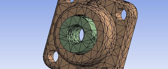
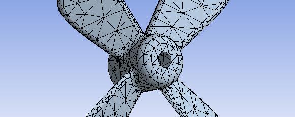
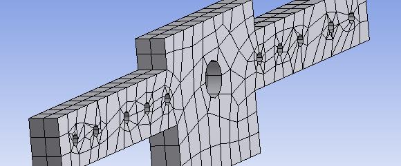
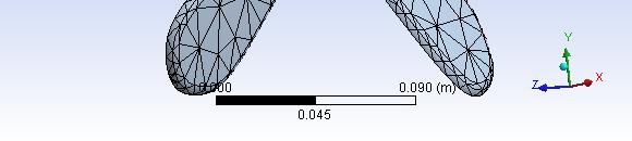
15 COMPUTER SIMULATION WITH ANSYS WORKBENCH (CONT.) ( ) Finite Element Analysis Mesh convergence study and geometry Fig. 14:mesh around the crack region Fig. 15: Finite Element mesh used for the various components of the rotating shaft system 15
16 Presentation of results and discussion Experimental and numerical results TABLE# 2: EXPERIMENTAL VALUES OF NATURAL FREQUENCIES FOR VARIOUS CRACK DEPT RATIOS (NUMERICAL VALUES SHOWN WITHIN BRACKETS V VERTICAL AND H HORIZONTAL AND TORSIONAL). 16 First Second Third Fourth First natural frequency for torsion Frequency Crack depth ratios 0.0% 10% 20% 30% V H V H V H V H Exp. Shaft 1 * Exp. Shaft 2 * Exp. Shaft 3 * Num. Comp Exp. Shaft 1 * Exp. Shaft 2 * Exp. Shaft 3 * Num. Comp Exp. Shaft 1 * Exp. Shaft 2 * Exp. Shaft 3 * Num. Comp Exp. Shaft 1 * Exp. Shaft 2 * Exp. Shaft 3 * Num. Comp Exp. Shaft Num. Comp
17 Presentation of results and discussion (CONT.) Experimental and numerical results p TABLE# 2: EXPERIMENTAL VALUES OF NATURAL FREQUENCIES FOR VARIOUS CRACK DEPT RATIOS (NUMERICAL VALUES SHOWN WITHIN BRACKETS V VERTICAL AND H HORIZONTAL AND TORSIONAL). First Second Third Frequency Crack depth ratios 0.40% 50% 60% 70% V H V H V H V H Exp. Shaft 1 * Exp. Shaft 2 * Exp. Shaft 3 * Num. Comp Exp. Shaft 1 * Exp. Shaft 2 * Exp. Shaft 3 * Num. Comp Exp. Shaft 1 * Exp. Shaft 2 * Exp. Shaft hf 3 * Fourth First natural frequency for torsion Num. Comp Exp. Shaft 1 * Exp. Shaft 2 * Exp. Shaft 3 * Num. Comp Exp. Shaft Num. Comp
18 Presentation of results and discussion (CONT.) Experimental and numerical results Fig. 16: Responses of the system in terms of FRFs for experimental and numerical results For velocity VRFs. Fig. 17: Comparison responses functions (VRF) in experimental and numerical computations Intact VRFs; Cracked 20% VRFs; and Cracked 40% VRFs 18
 Experimental and numerical results Fig.")

19 Presentation of results and discussion (CONT.) Experimental and numerical results Fig. 18: Change of the impedances with crack depth for both experimental and numerical results Fig. 19: Variation of experimental and numerical impedance for different crack depths 19
20 Presentation of results and discussion (CONT.) Experimental and numerical results (b) (a) Figure 20. Changes in the a) mobility and b) impedance between intact and 70% crack depth ratio for experimental and numerical results for shaft # 2 20
 Experimental and numerical results (a) (b) Fig 21: Comparison of experimental and numerical results for: a)")
 experimental and numerical frequency ratio versus crack")
21 Presentation of results and discussion (CONT.) Experimental and numerical results (a) (b) Fig 21: Comparison of experimental and numerical results for: a) experimental and (c) Fig. 21: Comparison of experimental and numerical results for: a) experimental and numerical frequency ratio versus crack depth ratio; b) the relationship between numerical and experimental results of frequency ratio; and c) experimental and numerical slope of the frequency ratio for fourth modes. 21
 Experimental and Numerical Anti Resonant Frequency Ratio results (a) (b)")

 experimental and numerical slope of the")
22 Presentation of results and discussion (CONT.) Experimental and Numerical Anti Resonant Frequency Ratio results (a) (b) (c) Figure 22: Comparison of experimental and numerical results for: a) experimental and numerical ant-resonant frequency ratio versus crack depth ratio; b) the relationship between numerical and experimental results of anti-resonant frequency ratio and c) experimental and numerical slope of the frequency ratio for first and third modes. 22
 experimental and numerical torsional frequency ratio versus crack depth ratio; and b) experimental and numerical torsional slope of the")
23 Presentation of results and discussion (CONT.) Experimental and numerical results (a) () (b) Fig. 23: Comparison of experimental and numerical results for: a) experimental and numerical torsional frequency ratio versus crack depth ratio; and b) experimental and numerical torsional slope of the frequency ratio for first mode. (a) (b) Fig. 24: Comparison of experimental and numerical results for: a) amplitude ratio versus crack depth ratio; and b) slope of impedance amplitude versus crack depth ratio 23
24 CONCLUSIONS Effects of a transverse open surface crack on a shaft investigated The experimental and numerical results seem to be agreeing very well frequencies of the cracked kdshaft hftdecrease as thecrack depth thincreases. Mechanical impedance is also used It seems to show more sensitive for identifying the crack Impedance and mobility were measured and simulated in the vertical direction. Theamplitudes of all the mobility curves increase for the resonantfrequencies for increasing crack depth. In contrast, the amplitudes of impedance at all the anti resonant frequencies either decrease (at the first anti resonance) or increase(at the third anti resonance). Overall, the trend of agreement between experimental and numerical values is very good. 24
25 CONCLUSIONS (CONT.) At lower crack depth ratios (<0.4) the relationship between experimental and numerical non dimensional frequencies is almost linear; as crack depth increases beyond this, the frequency ratio tends to become slightly nonlinear. This seems to imply that the nonlinear effect on the resonant frequencies is marginal at crack depth ratios less than 0.4; even beyond this crack depth ratio the effect is not significant. ifi A better crack detection measure is obtained when the slope of the frequency ratio vs. crack depth ratio curve is plotted against the crack depth ratio. 25
26 CONCLUSIONS (CONT.) Conclusions derived for anti resonant frequencies are, almost similar to the ones that were made for the resonant frequencies. The torsional frequency ratio vs. crack depth ratio for experimental and numerical analysis show that the change in the frequency ratio gives a much better indication of the crack presence even from the beginning stages of the crack. The uses of impedance amplitudes seem to give more sensitive indications regarding the presence and severity of crack. 26
27 ACKNOWLEDGEMENTS The authors would like to express their sincere gratitude To the Staff of the estructural Lab of the Faculty of Engineering and Applied Science at the Memorial University. They also for would like to thank the funding agency (National Research Council of Canada) for funding the costs of experimental specimens 27
28 28
Crack Detection in Shafts Using Mechanical Impedance Measurements
 Mechanical Engineering Research; Vol. 2, No. 2; 2012 ISSN 1927-0607 E-ISSN 1927-0615 Published by Canadian Center of Science and Education Crack Detection in Shafts Using Mechanical Impedance Measurements
Finite Element Analysis Lecture 1. Dr./ Ahmed Nagib
 Finite Element Analysis Lecture 1 Dr./ Ahmed Nagib April 30, 2016 Research and Development Mathematical Model Mathematical Model Mathematical Model Finite Element Analysis The linear equation of motion
Chapter 5. Vibration Analysis. Workbench - Mechanical Introduction ANSYS, Inc. Proprietary 2009 ANSYS, Inc. All rights reserved.
 Workbench - Mechanical Introduction 12.0 Chapter 5 Vibration Analysis 5-1 Chapter Overview In this chapter, performing free vibration analyses in Simulation will be covered. In Simulation, performing a
Experiment Two (2) Torsional testing of Circular Shafts
 Torsional testing of Circular Shafts") Experiment Two (2) Torsional testing of Circular Shafts Introduction: Torsion occurs when any shaft is subjected to a torque. This is true whether the shaft is rotating (such as drive shafts on engines,
Experiment Two (2) Torsional testing of Circular Shafts Introduction: Torsion occurs when any shaft is subjected to a torque. This is true whether the shaft is rotating (such as drive shafts on engines,
Design of the Deployment Mechanism of Solar Array on a Small Satellite
 American Journal of Mechanical Engineering, 2013, Vol. 1, No. 3, 66-72 Available online at http://pubs.sciepub.com/ajme/1/3/2 Science and Education Publishing DOI:10.12691/ajme-1-3-2 Design of the Deployment
Multiple Cracks Effects on Vibration Characteristics of Shaft Beam
 International Journal of Engineering Research and General Science Volume 3, Issue, January-February, 205 Multiple Cracks Effects on Vibration Characteristics of Shaft Beam Prof. D. R. Satpute, Prof. S.
Fluid structure interaction dynamic analysis of a mixed-flow waterjet pump
 IOP Conference Series: Materials Science and Engineering OPEN ACCESS Fluid structure interaction dynamic analysis of a mixed-flow waterjet pump To cite this article: X W Pan et al 2013 IOP Conf. Ser.:
Effect of Angular movement of Lifting Arm on Natural Frequency of Container Lifting Mechanism using Finite Element Modal Analysis
 Effect of Angular movement of Lifting Arm on Natural Frequency of Container Lifting Mechanism using Finite Element Modal Analysis Khodu M Dhameliya, 2 Utpal V Shah, 3 Dhaval Makwana, 4 Mansi Yadav, 5 Ishankumar
Deflections and Strains in Cracked Shafts Due to Rotating Loads: A Numerical and Experimental Analysis
 International Journal of Rotating Machinery, 9: 303 311, 2003 Copyright c Taylor & Francis Inc. ISSN: 1023-621X DOI: 10.1080/10236210390147416 Deflections and Strains in Cracked Shafts Due to Rotating
NUMERICAL MODELLING OF RUBBER VIBRATION ISOLATORS
 NUMERICAL MODELLING OF RUBBER VIBRATION ISOLATORS Clemens A.J. Beijers and André de Boer University of Twente P.O. Box 7, 75 AE Enschede, The Netherlands email: c.a.j.beijers@utwente.nl Abstract An important
DEPARTMENT OF MECHANICAL ENIGINEERING, UNIVERSITY OF ENGINEERING & TECHNOLOGY LAHORE (KSK CAMPUS).
.") DEPARTMENT OF MECHANICAL ENIGINEERING, UNIVERSITY OF ENGINEERING & TECHNOLOGY LAHORE (KSK CAMPUS). Lab Director: Coordinating Staff: Mr. Muhammad Farooq (Lecturer) Mr. Liaquat Qureshi (Lab Supervisor)
DEPARTMENT OF MECHANICAL ENIGINEERING, UNIVERSITY OF ENGINEERING & TECHNOLOGY LAHORE (KSK CAMPUS). Lab Director: Coordinating Staff: Mr. Muhammad Farooq (Lecturer) Mr. Liaquat Qureshi (Lab Supervisor)
Nonlinear Rolling Element Bearings in MADYN 2000 Version 4.3
 - 1 - Nonlinear Rolling Element Bearings in MADYN 2000 Version 4.3 In version 4.3 nonlinear rolling element bearings can be considered for transient analyses. The nonlinear forces are calculated with a
Deflections and Strains in Cracked Shafts due to Rotating Loads: A Numerical and Experimental Analysis
 Rotating Machinery, 10(4): 283 291, 2004 Copyright c Taylor & Francis Inc. ISSN: 1023-621X print / 1542-3034 online DOI: 10.1080/10236210490447728 Deflections and Strains in Cracked Shafts due to Rotating
AERO 214. Lab II. Measurement of elastic moduli using bending of beams and torsion of bars
 AERO 214 Lab II. Measurement of elastic moduli using bending of beams and torsion of bars BENDING EXPERIMENT Introduction Flexural properties of materials are of interest to engineers in many different
Vibration Analysis of Multiple Cracked Shaft
 International OPEN ACCESS Journal Of Modern Engineering Research (IJMER) Vibration Analysis of Multiple Cracked Shaft Dinesh R. Satpute 1, Milind S. Mhaske 2, Prof. S. B. Belkar 3 1 ( PG Scholar, Pravara
The University of Melbourne Engineering Mechanics
 The University of Melbourne 436-291 Engineering Mechanics Tutorial Four Poisson s Ratio and Axial Loading Part A (Introductory) 1. (Problem 9-22 from Hibbeler - Statics and Mechanics of Materials) A short
Cantilever Beam Crack Detection using FEA and FFT Analyser
 Cantilever Beam Detection using FEA and FFT Analyser Pooja Ghumai 1, Dr. L G Navale 2 1ME Student, DesignEngg, DYPIT, Pimpri, Pune 2Professor, DesignEngg, DYPIT, Pimpri, Pune ---------------------------------------------------------------------***---------------------------------------------------------------------
ANALYSIS AND IDENTIFICATION IN ROTOR-BEARING SYSTEMS
 ANALYSIS AND IDENTIFICATION IN ROTOR-BEARING SYSTEMS A Lecture Notes Developed under the Curriculum Development Scheme of Quality Improvement Programme at IIT Guwahati Sponsored by All India Council of
International Journal of Scientific & Engineering Research, Volume 7, Issue 4, April ISSN STRUCTURAL ANALYSIS OF DUAL BRAKE SYSTEM
 International Journal of Scientific & Engineering Research, Volume 7, Issue 4, April-2016 71 STRUCTURAL ANALYSIS OF DUAL BRAKE SYSTEM Yuvaperiyasamy M 1, Kailasam R 2, Premkumar R 3 Vinothkumar S 4 Assistant
3 Hours/100 Marks Seat No.
 *17304* 17304 14115 3 Hours/100 Marks Seat No. Instructions : (1) All questions are compulsory. (2) Illustrate your answers with neat sketches wherever necessary. (3) Figures to the right indicate full
Dynamic (Vibrational) and Static Structural Analysis of Ladder Frame
 and Static Structural Analysis of Ladder Frame") Dynamic (Vibrational) and Static Structural Analysis of Ladder Frame Ketan Gajanan Nalawade 1, Ashish Sabu 2, Baskar P 3 School of Mechanical and building science, VIT University, Vellore-632014, Tamil
Dynamic (Vibrational) and Static Structural Analysis of Ladder Frame Ketan Gajanan Nalawade 1, Ashish Sabu 2, Baskar P 3 School of Mechanical and building science, VIT University, Vellore-632014, Tamil
Structural Dynamics Model Calibration and Validation of a Rectangular Steel Plate Structure
 Structural Dynamics Model Calibration and Validation of a Rectangular Steel Plate Structure Hasan G. Pasha, Karan Kohli, Randall J. Allemang, Allyn W. Phillips and David L. Brown University of Cincinnati
Vibration analysis of free isotropic cracked plates
 Computational Methods and Experimental Measurements XII 475 Vibration analysis of free isotropic cracked plates M. Alfano & L. Pagnotta Department of Mechanical Engineering, University of Calabria, Italy
BEAM DEFLECTION THE ELASTIC CURVE
 BEAM DEFLECTION Samantha Ramirez THE ELASTIC CURVE The deflection diagram of the longitudinal axis that passes through the centroid of each cross-sectional area of a beam. Supports that apply a moment
Finite Element Simulation of Bar-Plate Friction Welded Joints Steel Product Subjected to Impact Loading
 Finite Element Simulation of Bar-Plate Friction Welded Joints Steel Product Subjected to Impact Loading Yohanes, a,* Muftil Badri, a Panji Adino, a Dodi Sofyan Arief, a and Musthafa Akbar, a a) Department
STANDARD SAMPLE. Reduced section " Diameter. Diameter. 2" Gauge length. Radius
 MATERIAL PROPERTIES TENSILE MEASUREMENT F l l 0 A 0 F STANDARD SAMPLE Reduced section 2 " 1 4 0.505" Diameter 3 4 " Diameter 2" Gauge length 3 8 " Radius TYPICAL APPARATUS Load cell Extensometer Specimen
2012 MECHANICS OF SOLIDS
 R10 SET - 1 II B.Tech II Semester, Regular Examinations, April 2012 MECHANICS OF SOLIDS (Com. to ME, AME, MM) Time: 3 hours Max. Marks: 75 Answer any FIVE Questions All Questions carry Equal Marks ~~~~~~~~~~~~~~~~~~~~~~
Mechanics of Materials II. Chapter III. A review of the fundamental formulation of stress, strain, and deflection
 Mechanics of Materials II Chapter III A review of the fundamental formulation of stress, strain, and deflection Outline Introduction Assumtions and limitations Axial loading Torsion of circular shafts
Stability for Bridge Cable and Cable-Deck Interaction. Dr. Maria Rosaria Marsico D.J. Wagg
 Stability for Bridge Cable and Cable-Deck Interaction Dr. Maria Rosaria Marsico D.J. Wagg S.A. Neild Introduction The interaction between cables and structure can lead to complex vibration response Cables
D : SOLID MECHANICS. Q. 1 Q. 9 carry one mark each.
 GTE 2016 Q. 1 Q. 9 carry one mark each. D : SOLID MECHNICS Q.1 single degree of freedom vibrating system has mass of 5 kg, stiffness of 500 N/m and damping coefficient of 100 N-s/m. To make the system
Absolute Nonlinear Parameter Estimation using Relative Nonlinear Parameter measured from Surface Acoustic Wave
 Absolute Nonlinear Parameter Estimation using Relative Nonlinear Parameter measured from Surface Acoustic Wave J. H. Jun 1, H. G. Seo 1, Y. D. Shim 1 and K. Y. Jhang 1, School of Mechanical Engineering,
Experimental and numerical investigation of modal properties for liquid-containing structures
 Journal of Mechanical Science and Technology 6 (5) (0) 9~5 www.springerlink.com/content/738-9x DOI 0.007/s06-0-0336- Experimental and numerical investigation of modal properties for liquid-containing structures
INTRODUCTION TO STRAIN
 SIMPLE STRAIN INTRODUCTION TO STRAIN In general terms, Strain is a geometric quantity that measures the deformation of a body. There are two types of strain: normal strain: characterizes dimensional changes,
Lab Exercise #5: Tension and Bending with Strain Gages
 Lab Exercise #5: Tension and Bending with Strain Gages Pre-lab assignment: Yes No Goals: 1. To evaluate tension and bending stress models and Hooke s Law. a. σ = Mc/I and σ = P/A 2. To determine material
Brake Squeal Analysis
 Brake Squeal Analysis João G. P. da Silva Fras-le Érico R. Fulco Fras-le Paulo E. D. Variante Fras-le Vagner do Nascimento - Master Fabiano N. Diesel - ESSS Daniel Boniatti - ESSS Introduction Brake disc
The Torsion Pendulum (One or two weights)
") The Torsion Pendulum (One or two weights) Exercises I through V form the one-weight experiment. Exercises VI and VII, completed after Exercises I -V, add one weight more. Preparatory Questions: 1. The
The Torsion Pendulum (One or two weights) Exercises I through V form the one-weight experiment. Exercises VI and VII, completed after Exercises I -V, add one weight more. Preparatory Questions: 1. The
Module 10: Free Vibration of an Undampened 1D Cantilever Beam
 Module 10: Free Vibration of an Undampened 1D Cantilever Beam Table of Contents Page Number Problem Description Theory Geometry 4 Preprocessor 6 Element Type 6 Real Constants and Material Properties 7
2044. Dynamics analysis for the clamping mechanisms of a rotary inchworm piezoelectric motor
 2044. Dynamics analysis for the clamping mechanisms of a rotary inchworm piezoelectric motor Yongfei Gu 1, Jichun Xing 2 1, 2 School of Mechanical Engineering, Yanshan University, Qinhuangdao, China 1
Lab Exercise #3: Torsion
 Lab Exercise #3: Pre-lab assignment: Yes No Goals: 1. To evaluate the equations of angular displacement, shear stress, and shear strain for a shaft undergoing torsional stress. Principles: testing of round
CHAPTER 4 FAULT DIAGNOSIS OF BEARINGS DUE TO SHAFT RUB
 53 CHAPTER 4 FAULT DIAGNOSIS OF BEARINGS DUE TO SHAFT RUB 4.1 PHENOMENON OF SHAFT RUB Unwanted contact between the rotating and stationary parts of a rotating machine is more commonly referred to as rub.
COUPLED USE OF FEA AND EMA FOR THE INVESTIGATION OF DYNAMIC BEHAVIOUR OF AN INJECTION PUMP
 COUPLED USE OF FEA AND EMA FOR THE INVESTIGATION OF DYNAMIC BEHAVIOUR OF AN INJECTION PUMP Yasar Deger Wolfram Lienau Peter Sandford Sulzer Markets & Sulzer Pumps Ltd Sulzer Pumps (UK) Ltd Technology Ltd
Members Subjected to Torsional Loads
 Members Subjected to Torsional Loads Torsion of circular shafts Definition of Torsion: Consider a shaft rigidly clamped at one end and twisted at the other end by a torque T = F.d applied in a plane perpendicular
1653. Effect of cut-out on modal properties of edge cracked temperature-dependent functionally graded plates
 1653. Effect of cut-out on modal properties of edge cracked temperature-dependent functionally graded plates A. Shahrjerdi 1, T. Ezzati 2 1 Department of Mechanical Engineering, Malayer University, Malayer
[7] Torsion. [7.1] Torsion. [7.2] Statically Indeterminate Torsion. [7] Torsion Page 1 of 21
![[7] Torsion. [7.1] Torsion. [7.2] Statically Indeterminate Torsion. [7] Torsion Page 1 of 21](/thumbs/88/115835122.jpg "[7] Torsion. [7.1] Torsion. [7.2] Statically Indeterminate Torsion. [7] Torsion Page 1 of 21") [7] Torsion Page 1 of 21 [7] Torsion [7.1] Torsion [7.2] Statically Indeterminate Torsion [7] Torsion Page 2 of 21 [7.1] Torsion SHEAR STRAIN DUE TO TORSION 1) A shaft with a circular cross section is
[7] Torsion Page 1 of 21 [7] Torsion [7.1] Torsion [7.2] Statically Indeterminate Torsion [7] Torsion Page 2 of 21 [7.1] Torsion SHEAR STRAIN DUE TO TORSION 1) A shaft with a circular cross section is
Finite Element Analysis of Piezoelectric Cantilever
 Finite Element Analysis of Piezoelectric Cantilever Nitin N More Department of Mechanical Engineering K.L.E S College of Engineering and Technology, Belgaum, Karnataka, India. Abstract- Energy (or power)
Analysis on propulsion shafting coupled torsional-longitudinal vibration under different applied loads
 Analysis on propulsion shafting coupled torsional-longitudinal vibration under different applied loads Qianwen HUANG 1 ; Jia LIU 1 ; Cong ZHANG 1,2 ; inping YAN 1,2 1 Reliability Engineering Institute,
[5] Stress and Strain
![[5] Stress and Strain](/thumbs/95/123344550.jpg "[5] Stress and Strain") [5] Stress and Strain Page 1 of 34 [5] Stress and Strain [5.1] Internal Stress of Solids [5.2] Design of Simple Connections (will not be covered in class) [5.3] Deformation and Strain [5.4] Hooke s Law
[5] Stress and Strain Page 1 of 34 [5] Stress and Strain [5.1] Internal Stress of Solids [5.2] Design of Simple Connections (will not be covered in class) [5.3] Deformation and Strain [5.4] Hooke s Law
Simarnjit Singh 1, Amandeep Singh 2 1 Research Scholar, 2 Assistant Professor, Mechanical Engineering Department, CTIEMT Jalandhar
 Free Vibration Analysis of Differernt aterials under Crack as a Cantilever Beam Simarnjit Singh 1, Amandeep Singh 2 1 Research Scholar, 2 Assistant Professor, echanical Engineering Department, CTIET Jalandhar
Tensile stress strain curves for different materials. Shows in figure below
 Tensile stress strain curves for different materials. Shows in figure below Furthermore, the modulus of elasticity of several materials effected by increasing temperature, as is shown in Figure Asst. Lecturer
9 MECHANICAL PROPERTIES OF SOLIDS
 9 MECHANICAL PROPERTIES OF SOLIDS Deforming force Deforming force is the force which changes the shape or size of a body. Restoring force Restoring force is the internal force developed inside the body
SICODYN : benchmark pour l évaluation du calcul dynamique et du recalage sur une structure industrielle
 SICODYN : benchmark pour l évaluation du calcul dynamique et du recalage sur une structure industrielle Sylvie AUDEBERT, Charles BODEL EDF R&D Acoustics and Mechanical Analyses Department Outline 1. SICODYN
OPTI 521, Optomechanical Design, Technical Paper Reviews, Dr. Jim Burge, 2011
 Synopsis of Predicting the vibration characteristics of elements incorporating Incompressible and Compressible Viscoelastic Materials Abstract Jacob Etter OPTI 521, University of Arizona, College of Optical
Stress Analysis Lecture 3 ME 276 Spring Dr./ Ahmed Mohamed Nagib Elmekawy
 Stress Analysis Lecture 3 ME 276 Spring 2017-2018 Dr./ Ahmed Mohamed Nagib Elmekawy Axial Stress 2 Beam under the action of two tensile forces 3 Beam under the action of two tensile forces 4 Shear Stress
Structural Analysis I Chapter 4 - Torsion TORSION
 ORSION orsional stress results from the action of torsional or twisting moments acting about the longitudinal axis of a shaft. he effect of the application of a torsional moment, combined with appropriate
Cardan s Coupling Shaft as a Dynamic Evolutionary System
 American Journal of Modern Physics and Application 2017; 4(2): 6-11 http://www.openscienceonline.com/journal/ajmpa Cardan s Coupling Shaft as a Dynamic Evolutionary System Petr Hrubý 1, Zdeněk Hlaváč 2,
RESILIENT INFRASTRUCTURE June 1 4, 2016
 RESILIENT INFRASTRUCTURE June 1 4, 2016 DAMAGE DETECTION OF UHP-FRC PLATES USING RANDOM DECREMENT TECHNIQUE Azita Pourrastegar MASc Student, Ryerson University, azita2.pourrastegar@ryerson.ca, Canada Hesham
R13. II B. Tech I Semester Regular Examinations, Jan MECHANICS OF SOLIDS (Com. to ME, AME, AE, MTE) PART-A
 PART-A") SET - 1 II B. Tech I Semester Regular Examinations, Jan - 2015 MECHANICS OF SOLIDS (Com. to ME, AME, AE, MTE) Time: 3 hours Max. Marks: 70 Note: 1. Question Paper consists of two parts (Part-A and Part-B)
SET - 1 II B. Tech I Semester Regular Examinations, Jan - 2015 MECHANICS OF SOLIDS (Com. to ME, AME, AE, MTE) Time: 3 hours Max. Marks: 70 Note: 1. Question Paper consists of two parts (Part-A and Part-B)
PES Institute of Technology
 PES Institute of Technology Bangalore south campus, Bangalore-5460100 Department of Mechanical Engineering Faculty name : Madhu M Date: 29/06/2012 SEM : 3 rd A SEC Subject : MECHANICS OF MATERIALS Subject
Chapter Objectives. Copyright 2011 Pearson Education South Asia Pte Ltd
 Chapter Objectives To determine the torsional deformation of a perfectly elastic circular shaft. To determine the support reactions when these reactions cannot be determined solely from the moment equilibrium
VIBRO-THERMOGRAPHY OF DEBONDING DEFECTS IN COMPOSITE PLATES
 http://dx.doi.org/10.1611/qirt.017.06 VIBRO-THERMOGRAPHY OF DEBONDING DEFECTS IN COMPOSITE PLATES Liang Zhu, Xingwang Guo Beihang University, 37 Xue Yuan Rd. Haidian District, Beijing 100191,China ABSTRACT
ISSN (ONLINE): , ISSN (PRINT):
: , ISSN (PRINT):") Volume-5, Issue-2, April-2015 International Journal of Engineering and Management Research Page Number: 819-829 Vibration Effect of Different Number of Cracks, Length of Cracks, Cutting Teeth, Holes, Slits,
Volume-5, Issue-2, April-2015 International Journal of Engineering and Management Research Page Number: 819-829 Vibration Effect of Different Number of Cracks, Length of Cracks, Cutting Teeth, Holes, Slits,
Dynamic behavior of turbine foundation considering full interaction among facility, structure and soil
 Dynamic behavior of turbine foundation considering full interaction among facility, structure and soil Fang Ming Scholl of Civil Engineering, Harbin Institute of Technology, China Wang Tao Institute of
Department of Mechanical FTC College of Engineering & Research, Sangola (Maharashtra), India.
, India.") VALIDATION OF VIBRATION ANALYSIS OF ROTATING SHAFT WITH LONGITUDINAL CRACK 1 S. A. Todkar, 2 M. D. Patil, 3 S. K. Narale, 4 K. P. Patil 1,2,3,4 Department of Mechanical FTC College of Engineering & Research,
VALIDATION OF VIBRATION ANALYSIS OF ROTATING SHAFT WITH LONGITUDINAL CRACK 1 S. A. Todkar, 2 M. D. Patil, 3 S. K. Narale, 4 K. P. Patil 1,2,3,4 Department of Mechanical FTC College of Engineering & Research,
Stress-Strain Behavior
 Stress-Strain Behavior 6.3 A specimen of aluminum having a rectangular cross section 10 mm 1.7 mm (0.4 in. 0.5 in.) is pulled in tension with 35,500 N (8000 lb f ) force, producing only elastic deformation.
ME Final Exam. PROBLEM NO. 4 Part A (2 points max.) M (x) y. z (neutral axis) beam cross-sec+on. 20 kip ft. 0.2 ft. 10 ft. 0.1 ft.
 M (x) y. z (neutral axis) beam cross-sec+on. 20 kip ft. 0.2 ft. 10 ft. 0.1 ft.") ME 323 - Final Exam Name December 15, 2015 Instructor (circle) PROEM NO. 4 Part A (2 points max.) Krousgrill 11:30AM-12:20PM Ghosh 2:30-3:20PM Gonzalez 12:30-1:20PM Zhao 4:30-5:20PM M (x) y 20 kip ft 0.2
ME 323 - Final Exam Name December 15, 2015 Instructor (circle) PROEM NO. 4 Part A (2 points max.) Krousgrill 11:30AM-12:20PM Ghosh 2:30-3:20PM Gonzalez 12:30-1:20PM Zhao 4:30-5:20PM M (x) y 20 kip ft 0.2
On The Finite Element Modeling Of Turbo Machinery Rotors In Rotor Dynamic Analysis
 Proceedings of The Canadian Society for Mechanical Engineering International Congress 2018 CSME International Congress 2018 May 27-30, 2018, Toronto, On, Canada On The Finite Element Modeling Of Turbo
Due Date 1 (for confirmation of final grade): Monday May 10 at 11:59pm Due Date 2 (absolute latest possible submission): Friday May 14 at 5pm
: Monday May 10 at 11:59pm Due Date 2 (absolute latest possible submission): Friday May 14 at 5pm") ! ME345 Modeling and Simulation, Spring 2010 Case Study 3 Assigned: Friday April 16! Due Date 1 (for email confirmation of final grade): Monday May 10 at 11:59pm Due Date 2 (absolute latest possible submission):
! ME345 Modeling and Simulation, Spring 2010 Case Study 3 Assigned: Friday April 16! Due Date 1 (for email confirmation of final grade): Monday May 10 at 11:59pm Due Date 2 (absolute latest possible submission):
2014 MECHANICS OF MATERIALS
 R10 SET - 1 II. Tech I Semester Regular Examinations, March 2014 MEHNIS OF MTERILS (ivil Engineering) Time: 3 hours Max. Marks: 75 nswer any FIVE Questions ll Questions carry Equal Marks ~~~~~~~~~~~~~~~~~~~~~~~~~
Crack detection in cantilever beam by frequency based method
 Available online at www.sciencedirect.com Procedia Engineering 51 ( 2013 ) 770 775 Chemical, Civil and Mechanical Engineering Tracks of 3 rd Nirma University International Conference on Engineering (NUiCONE
Hardened Concrete. Lecture No. 16
 Hardened Concrete Lecture No. 16 Fatigue strength of concrete Modulus of elasticity, Creep Shrinkage of concrete Stress-Strain Plot of Concrete At stress below 30% of ultimate strength, the transition
COMPOUND PENDULUM. AIM: 01. To determine the radius of gyration k of given compo pendulum. 02. To verify the relation
 COMPOUND PENDULUM AIM: 01. To determine the radius of gyration k of given compo pendulum. 02. To verify the relation T= 2 π 2 2 K + (OG) g (OG) Where, T = Periodic time sec. K = Radius of gyration about
PLEASURE VESSEL VIBRATION AND NOISE FINITE ELEMENT ANALYSIS
 PLEASURE VESSEL VIBRATION AND NOISE FINITE ELEMENT ANALYSIS 1 Macchiavello, Sergio *, 2 Tonelli, Angelo 1 D Appolonia S.p.A., Italy, 2 Rina Services S.p.A., Italy KEYWORDS pleasure vessel, vibration analysis,
NONLINEAR CHARACTERISTICS OF THE PILE-SOIL SYSTEM UNDER VERTICAL VIBRATION
 IGC 2009, Guntur, INDIA NONLINEAR CHARACTERISTICS OF THE PILE-SOIL SYSTEM UNDER VERTICAL VIBRATION B. Manna Lecturer, Civil Engineering Department, National Institute of Technology, Rourkela 769008, India.
Modal and Harmonic Response Analysis of PBGA and S-N Curve Creation of Solder Joints
 Sensors & Transducers 2013 by IFSA http://www.sensorsportal.com Modal and Harmonic Response Analysis of PBGA and S-N Curve Creation of Solder Joints 1 Yu Guo, 1 Kailin Pan, 1, 2 Xin Wang, 1, 2 Tao Lu and
Design Procedures For Dynamically Loaded Foundations
 Design Procedures For Dynamically Loaded Foundations 1/11 Choice of parameters for equivalent lumped systems Lumped mass : the mass of the foundation and supported machinery Damping : 1 Geometrical(or
Rock fragmentation mechanisms and an experimental study of drilling tools during high-frequency harmonic vibration
 Pet.Sci.(03)0:05- DOI 0.007/s8-03-068-3 05 Rock fragmentation mechanisms and an experimental study of drilling tools during high- harmonic vibration Li Wei, Yan Tie, Li Siqi and Zhang Xiaoning School of
OUTCOME 1 - TUTORIAL 3 BENDING MOMENTS. You should judge your progress by completing the self assessment exercises. CONTENTS
 Unit 2: Unit code: QCF Level: 4 Credit value: 15 Engineering Science L/601/1404 OUTCOME 1 - TUTORIAL 3 BENDING MOMENTS 1. Be able to determine the behavioural characteristics of elements of static engineering
STRESS STRAIN AND DEFORMATION OF SOLIDS, STATES OF STRESS
 1 UNIT I STRESS STRAIN AND DEFORMATION OF SOLIDS, STATES OF STRESS 1. Define: Stress When an external force acts on a body, it undergoes deformation. At the same time the body resists deformation. The
[Yadav*, 5(3): March, 2016] ISSN: (I2OR), Publication Impact Factor: 3.785
![[Yadav*, 5(3): March, 2016] ISSN: (I2OR), Publication Impact Factor: 3.785](/thumbs/85/92763355.jpg "[Yadav*, 5(3): March, 2016] ISSN: (I2OR), Publication Impact Factor: 3.785") IJESRT INTERNATIONAL JOURNAL OF ENGINEERING SCIENCES & RESEARCH TECHNOLOGY EXPERIMENTAL STUDY ON THE STRUCTURAL HEALTH MONITORING ON A R.C.C. BEAM BASED ON PIEZOELECTRIC MATERIAL Praveen Kumar Yadav*,
IJESRT INTERNATIONAL JOURNAL OF ENGINEERING SCIENCES & RESEARCH TECHNOLOGY EXPERIMENTAL STUDY ON THE STRUCTURAL HEALTH MONITORING ON A R.C.C. BEAM BASED ON PIEZOELECTRIC MATERIAL Praveen Kumar Yadav*,
Effects of Structural Forces on the Dynamic Performance of High Speed Rotating Impellers.
 Effects of Structural Forces on the Dynamic Performance of High Speed Rotating Impellers. G Shenoy 1, B S Shenoy 1 and Raj C Thiagarajan 2 * 1 Dept. of Mechanical & Mfg. Engineering, Manipal Institute
2D Modeling of Elastic Wave Propagation in Solids Containing Closed Cracks with Friction
 2D Modeling of Elastic Wave Propagation in Solids Containing Closed Cracks with Friction S. Delrue 1, V. Aleshin 2, O. Bou Matar 2, K. Van Den Abeele 1 1 Wave Propagation & Signal Processing Research Group,
NORMAL STRESS. The simplest form of stress is normal stress/direct stress, which is the stress perpendicular to the surface on which it acts.
 NORMAL STRESS The simplest form of stress is normal stress/direct stress, which is the stress perpendicular to the surface on which it acts. σ = force/area = P/A where σ = the normal stress P = the centric
Dr. N.V.Srinivasulu, S.Jaikrishna, A.Navatha
 PSD Analysis of an Automobile Dash Panel Dr. N.V.Srinivasulu, S.Jaikrishna, A.Navatha Abstract:-In this paper, PSD analysis of an automobile dash panel is performed in order to reduce the vibrations that
Chapter 5 Torsion STRUCTURAL MECHANICS: CE203. Notes are based on Mechanics of Materials: by R. C. Hibbeler, 7th Edition, Pearson
 STRUCTURAL MECHANICS: CE203 Chapter 5 Torsion Notes are based on Mechanics of Materials: by R. C. Hibbeler, 7th Edition, Pearson Dr B. Achour & Dr Eng. K. El-kashif Civil Engineering Department, University
PHYSICS LAB Experiment 9 Fall 2004 THE TORSION PENDULUM
 PHYSICS 83 - LAB Experiment 9 Fall 004 THE TORSION PENDULUM In this experiment we will study the torsion constants of three different rods, a brass rod, a thin steel rod and a thick steel rod. We will
Conditions. 5 Page ,China. Cymbal transducer can. order to. applications. ELEMENT METHOD. boundary [1].
![Conditions. 5 Page ,China. Cymbal transducer can. order to. applications. ELEMENT METHOD. boundary [1].](/thumbs/87/95053700.jpg "Conditions. 5 Page ,China. Cymbal transducer can. order to. applications. ELEMENT METHOD. boundary [1].") International Journal of Research in Engineering and Science (IJRES)( ISSN (Online): 232-9364, ISSN (Print): 232-9356 Volume 3 Issue 6 ǁ June 215 ǁ PP.5-12 Model Analysis of Cymbal Generator Under Different
International Journal of Research in Engineering and Science (IJRES)( ISSN (Online): 232-9364, ISSN (Print): 232-9356 Volume 3 Issue 6 ǁ June 215 ǁ PP.5-12 Model Analysis of Cymbal Generator Under Different
The Design of a Multiple Degree of Freedom Flexure Stage with Tunable Dynamics for Milling Experimentation
 The Design of a Multiple Degree of Freedom Flexure Stage with Tunable Dynamics for Milling Experimentation Mark A. Rubeo *, Kadir Kiran *, and Tony L. Schmitz The University of North Carolina at Charlotte,
Outline. Tensile-Test Specimen and Machine. Stress-Strain Curve. Review of Mechanical Properties. Mechanical Behaviour
 Tensile-Test Specimen and Machine Review of Mechanical Properties Outline Tensile test True stress - true strain (flow curve) mechanical properties: - Resilience - Ductility - Toughness - Hardness A standard
Nonlinear Finite Element Modeling of Nano- Indentation Group Members: Shuaifang Zhang, Kangning Su. ME 563: Nonlinear Finite Element Analysis.
 ME 563: Nonlinear Finite Element Analysis Spring 2016 Nonlinear Finite Element Modeling of Nano- Indentation Group Members: Shuaifang Zhang, Kangning Su Department of Mechanical and Nuclear Engineering,
Feasibility of dynamic test methods in classification of damaged bridges
 Feasibility of dynamic test methods in classification of damaged bridges Flavio Galanti, PhD, MSc., Felieke van Duin, MSc. TNO Built Environment and Geosciences, P.O. Box 49, 26 AA, Delft, The Netherlands.
QUESTION BANK SEMESTER: III SUBJECT NAME: MECHANICS OF SOLIDS
 QUESTION BANK SEMESTER: III SUBJECT NAME: MECHANICS OF SOLIDS UNIT 1- STRESS AND STRAIN PART A (2 Marks) 1. Define longitudinal strain and lateral strain. 2. State Hooke s law. 3. Define modular ratio,
Solution to Multi-axial Fatigue Life of Heterogenic Parts & Components Based on Ansys. Na Wang 1, Lei Wang 2
 5th International Conference on Information Engineering for Mechanics and Materials (ICIMM 215) Solution to Multi-axial Fatigue Life of Heterogenic Parts & Components Based on Ansys Na Wang 1, Lei Wang
FREE VIBRATIONS OF FRAMED STRUCTURES WITH INCLINED MEMBERS
 FREE VIBRATIONS OF FRAMED STRUCTURES WITH INCLINED MEMBERS A Thesis submitted in partial fulfillment of the requirements for the degree of Bachelor of Technology in Civil Engineering By JYOTI PRAKASH SAMAL
High Tech High Top Hat Technicians. An Introduction to Solid Mechanics. Is that supposed to bend there?
 High Tech High Top Hat Technicians An Introduction to Solid Mechanics Or Is that supposed to bend there? Why don't we fall through the floor? The power of any Spring is in the same proportion with the
PROPELLER INDUCED STRUCTURAL VIBRATION THROUGH THE THRUST BEARING
 PROPELLER INDUCED TRUCTURAL VIBRATION THROUGH THE THRUT BEARING Jie Pan, Nabil Farag, Terry Lin and Ross Juniper* DEPARTMENT OF MECHANICAL AND MATERIAL ENGINEERING THE UNIVERITY OF WETERN AUTRALIA 35 TIRLING
TORSION TEST. Figure 1 Schematic view of torsion test
 TORSION TEST 1. THE PURPOSE OF THE TEST The torsion test is performed for determining the properties of materials like shear modulus (G) and shear yield stress ( A ). 2. IDENTIFICATIONS: Shear modulus:
A new cantilever beam-rigid-body MEMS gyroscope: mathematical model and linear dynamics
 Proceedings of the International Conference on Mechanical Engineering and Mechatronics Toronto, Ontario, Canada, August 8-10 2013 Paper No. XXX (The number assigned by the OpenConf System) A new cantilever
Non-linear Modal Behaviour in Cantilever Beam Structures
 Non-linear Modal Behaviour in Cantilever Beam Structures Thamthada Suwanwong and Paul.W.Bland* Department of Mechanical Engineering Simulation & Design, The Sirindhorn International Thai-German Graduate
EDEM DISCRETIZATION (Phase II) Normal Direction Structure Idealization Tangential Direction Pore spring Contact spring SPRING TYPES Inner edge Inner d
 Normal Direction Structure Idealization Tangential Direction Pore spring Contact spring SPRING TYPES Inner edge Inner d") Institute of Industrial Science, University of Tokyo Bulletin of ERS, No. 48 (5) A TWO-PHASE SIMPLIFIED COLLAPSE ANALYSIS OF RC BUILDINGS PHASE : SPRING NETWORK PHASE Shanthanu RAJASEKHARAN, Muneyoshi
Institute of Industrial Science, University of Tokyo Bulletin of ERS, No. 48 (5) A TWO-PHASE SIMPLIFIED COLLAPSE ANALYSIS OF RC BUILDINGS PHASE : SPRING NETWORK PHASE Shanthanu RAJASEKHARAN, Muneyoshi
ASSESMENT OF THE EFFECT OF BOUNDARY CONDITIONS ON CYLINDRICAL SHELL MODAL RESPONSES
 ASSESMENT OF THE EFFECT OF BOUNDARY CONDITIONS ON CYLINDRICAL SHELL MODAL RESPONSES ABSTRACT Eduards Skukis, Kaspars Kalnins, Olgerts Ozolinsh Riga Technical University Institute of Materials and Structures