Rak Part II: Shell structures. Antti H. Niemi Department of Civil and Structural Engineering
|
|
|
- Benedict Henderson
- 6 years ago
- Views:
Transcription
1 Rak Part II: Shell structures Antti H. Niemi Department of Civil and Structural Engineering
2 Practicalities

3 Teacher Antti H. Niemi Postdoctoral Researcher Computational Structural Engineering Office: R225b Office hours: Wed or when available 3
4 Learning outcomes Recognizing plate and shell components in load-bearing structures Understanding of the fundamentals of plate and shell theories Applying principles of virtual work and minimum potential energy for plate and shell structures Analysing plate and shell structures by using analytical and numerical methods 4
5 Content and workload Contents: I. Shell geometry (week 44, ) II. General linear theory of shells (week 45, ) III. Membrane theory of shells (week 46, ) IV. Theory of edge effects (week 47, ) V. Shell buckling test (week 48, ) VI. Project work and revision (week 49, ) Workload for part II: 2.5 ECTS ~ hours of work ~ 10 hours/week plus exam 5
6 Coursework and assignments Total maximum score is 60 points. Examinations: 48 points. Exercises, homeworks and project: 12 points (weekly average). Weekly assignments: One quiz (3 points) Two exercise problems (6 points) One turn-in homework (3 points) Exam dates: Second partial exam: Wed, 9 Dec, Final exams: Thu, Mar 3, 2016 & Thu, May 19,
7 Weekly schedule Period II: Lectures: Tue & Wed Exercises: Fri
8 Week I: Shells in engineering and shell geometry Readings: Chapters 10 & 11 from Ventsel, E., & Krauthammer, T. (2001). Thin Plates and Shells. New York (p. 658). CRC Press.
9 Learning outcomes for week I Recognizing shell components in load-bearing structures. (Must know) Ability to parametrize surfaces and visualize them. (Must know). Knowledge of the concepts of metric and curvature tensors of surfaces and ability to calculate them for given parametrizations. (Good to know) Knowledge of geometric classification of surfaces. (Good to know). 9
10 Shells in engineering

11 Haukilahti water tower Constructed in Renovated in Owned by HSY. Two nested water containers of total volume 4100 m 3. Height: 45,3 m. 11
12 Haukilahti water tower (cont.) Structural design was carried out by M.Sc. Ilmari Hyppänen. Fairly sophisticated application of plate and shell theories. A super-computer was needed to solve linear systems of algebraic equations with unknowns. 12
13 Applications of shell structures Civil and architectural engineering: Large-span roofs Liquid containers, water tanks Containment shells and cooling towers Mechanical engineering: Piping systems, pressure vessels Aircraft, rockets, missiles and submarines Biomechanics: Artery walls in human cardiovascular system 13
14 Benefits of shell structures Efficient load-carrying mechanism by combination of membrane and bending actions Very high stiffness combined with light weight High aesthetic value 14
15 Shell geometry
16 Generic definitions 3D Bodies which are bounded by two closely spaced surfaces are referred to as shells (kuorirakenne). The locus of points which lie at equal distances from these two surfaces is called the middle surface (keskipinta). The thickness (kuoren paksuus) of the shell at any point of the middle surface is defined as the length of the line segment connecting the bounding surfaces and perpendicular to the middle surface. 16
17 Generic definitions (cont.) The shell geometry is entirely determined by specifying the form of the middle surface and the thickness at each point. The thickness may vary in magnitude from point to point but, for simplicity, we assume that it is a constant denoted by. The most important geometric characteristic of shells is curvature (kaarevuus), which couples stretching and bending deformations. 17
18 Slenderness Usually, the term shell incorporates a thinness/slenderness (ohuus/hoikkuus) assumption. This means that the dimensionless or relative thickness (suhteellinen paksuus), where is some characteristic length associated to the shell middle surface, is small in comparison with unity. Typically in civil engineering we have 18


19 Geometry of surfaces Definition A parametric surface (parametrinen pinta) is a smooth map When vary over, then trace out a surface: 19
20 Geometry of surfaces (cont.) The parametric equations can be given in the form where and are unit vectors along the coordinate axes. The parameters are called curvilinear coordinates (käyräviivaiset koordinaatit) of a given surface. The curves are referred to as the coordinate curves (koordinaattikäyrät). 20

21 Example: Monge s patch 21


22 Example: hemispherical dome A hemispherical dome of radius R and centered at the origin can be parametrized as where. 22

23 Tangent vectors and arc length The vectors are tangent to the coordinate curves. The differential of the arc length can be written as so that 23
 Assuming that the curvilinear coordinates are orthogonal, that is we have")
24 Tangent vectors and arc length (cont.) Assuming that the curvilinear coordinates are orthogonal, that is we have The quantities are called Lamé parameters. 24

25 Normal curvature Consider an arbitrary curve defined on the surface by where is the arc length. The tangent to the curve is The principal normal of the curve is determined by where is the radius of curvature. 25
26 Normal curvature (cont.) Projection of the curvature vector to the normal of the surface is the normal curvature of the surface: where is called the curvature tensor of the surface. The metric tensor of the surface is defined as 26
 and it can be shown that the corresponding directions")
27 Principal curvatures The normal curvature can be written as where are the first and second fundamental forms of the surface. The normal curvature has two extremal values called the principal curvatures (pääkaarevuudet) and it can be shown that the corresponding directions are mutually orthogonal. 27
28 Principal curvatures (cont.) If the coordinate lines coincide with the directions of principal curvature at each point, then these coordinates are called principal curvature coordinates (pääkaarevuuskoordinaatit). In the principal curvature coordinates, we have The principal curvatures can then be determined as 28
29 Unit vectors Assuming principal curvature coordinates, we can define an orthogonal system of unit vectors on the surface: This system can be used to represent vector quantities (displacements, forces) defined on the shell middle surface. 29

30 Derivatives of the unit vectors Assuming principal curvature coordinates, the derivatives of the unit vectors can be written in terms of the geometric parameters as 30
31 Classification of shell/surface geometries
 2.")
32 Surface invariants The quantities are the mean curvature and Gaussian curvature. Points on the surface as classified based on the sign of the Gaussian curvature as follows 1. Elliptic, when K>0 (1/R 1 and 1/R 2 have the same signs) 2. Parabolic, when K=0 (1/R 1 =0 or 1/R 2 =0) 3. Hyperbolic, when K<0 (1/R 1 and 1/R 2 have different signs) 32
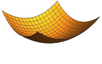
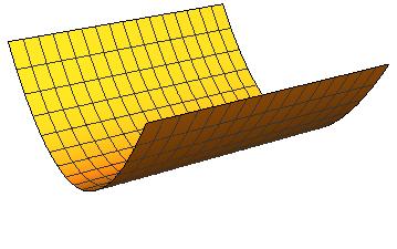
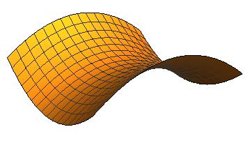
33 Classification based on Gaussian curvature 33
34 Surfaces of translation A surface of translation (translaatiopinta) is generated by a motion of a curve which is translated such that its points describe congruent curves. Roof structures often have a shape of a translation surface The equation of such surface can be prescribed as 34
 Paraboloid is a quadric surface that can be represented as Elliptic")
35 Surfaces of translation (cont.) Paraboloid is a quadric surface that can be represented as Elliptic paraboloid Parabolic paraboloid Hyperbolic paraboloid 35
 is such that")


36 Ruled surfaces A ruled surface (viivoitinpinta) is such that through every point on the surface there is a straight line that lies on the surface. Plane Hyperbolic paraboloid (doubly ruled) Cylinder 36
 is created when a plane curve, called meridian, rotates about an axis.")
37 Surfaces of revolution An important class of shells in engineering practice is shells of revolution (pyörähdyskuoret). A surface of revolution (pyörähdyspinta) is created when a plane curve, called meridian, rotates about an axis. If the curve is given in the form, and revolves around the -axis, then the natural parametrization is 37
38 Surfaces of revolution (cont.) Elimination of the parameters yields which is the equation for a surface of revolution. 38
39 Example: Cooling tower A line segment with end points (2,0,0) and (0,1,3) revolves around the z-axis. What is the parametric form of the surface? 39
40 Week II: General linear theory of shells Readings: Chapter 12 from Ventsel, E., & Krauthammer, T. (2001). Thin Plates and Shells. New York (p. 658). CRC Press.
41 Learning outcomes for week II Knowledge of the basic assumptions used in linear shell theories. (Must know) Knowledge of the physical and design quantities used in linear shell theories. (Must know) Ability to distinguish theories which take into account transverse shear deformations and theories which neglect them. (Good to know) Ability to derive equilibrium equations using the principle of minimum potential energy. (Nice to know) 41
42 Goal of shell theory According to W. Koiter and J. Simmons Shell theory attempts the impossible: to provide a two-dimensional representation of an intrinsically three-dimensional phenomenon. As in the theory of thin plates, the 3D problem of shell equilibirum can be reduced to essentially 2D problem formulated on the middle surface by imposing kinematic assumptions together with assumptions on the state of the stress. The formal process is known as dimension reduction (dimensioreduktio). 42
43 Fundamentals of shell theory
44 Basic assumptions 1. Straight material fibres which are perpendicular to the middle surface before deformation remain straight after deformation and do not change their length. 2. The normal stress to the middle surface vanishes in the normal direction. Assumption 1. is sometimes referred to as the Reissner-Mindlin kinematic assumption and assumption 2. as the plane stress assumption. 44
45 Perusoletukset suomeksi 1. Kuoren keskipintaa vasten kohtisuorat materiaalisäikeet, jotka ovat suoria ennen muodonmuutosta, säilyvät muodonmuutoksessa suorina eivätkä veny tai puristu. 2. Kuoren keskipinnan normaalin suuntainen normaalijännitys oletetaan häviävän pieneksi. 45
46 All you need is Love In addition to the above assumptions, the deformation of thin elastic shell is characacterized by the Kirchhoff-Love assumption: 3. Normal fibres to the undeformed middle surface remain normal after deformation Sama suomeksi: 3. Materiaalisäikeet jotka ovat kohtisuorassa kuoren keskipintaa vasten ennen muodonmuutosta, säilyvät kohtisuorassa muodonmuutoksen jälkeen. 46
47 Derivation of shell theories Shell theories can be developed from the general 3D theory of elasticity by the following steps: Formulation of a displacement Ansatz (yrite) according to the kinematic assumption. Expansion of the strain-displacement relations. Introduction of a constitutive law (compatible with the displacement Ansatz) to write stresses in terms of strains. Minimization of the total potential energy under prescribed kinematic constraints using variational methods or equilibrium equations. 47
48 Derivation of shell theories (cont.) The displacement Ansatz is formulated with respect to the assumed curvilinear coordinate system associated to the shell middle surface. When expanding the strain-displacement relations, variation of the basis vectors from point to point must be taken into account. We outline the process assuming that are principal curvature coordinates in context of linear theory of elasticity. 48
49 Shell kinematics

50 Displacement Ansatz The 3D shell domain may be described in the global Cartesian coordinate system as where and The Reissner-Mindlin kinematic assumption can be expressed as 50
51 Displacement Ansatz (cont.) The positive directions of the displacements coincide with the directions. The dimensionless quantities stand for the rotations of the normal to the middle surface (normaalin rotaatiot/ kiertymät) about tangents to the coordinate lines and, respectively. 51
52 Strain-displacement relations If is a system of Cartesian coordinates, then the linearized strain tensor is given by Let and define a local system of Cartesian coordinates by It follows that for 52
53 Strain-displacement relations (cont.) From the formulas for the derivatives of the unit vectors, we obtain at the point P : Chain rule yields: Which can be inverted up to the accuracy of as 53
 The derivatives of the displacement vector read The")
54 Strain-displacement relations (cont.) The derivatives of the displacement vector read The strains can be expanded as 54

55 Membrane strains The components of the membrane strain tensor come out as 55

56 Transverse shear strains The transverse shear strains are determined as 56
 tensor are 57")
57 Bending strains Reissner-Naghdi model The components of the bending strain (or elastic curvature) tensor are 57
58 Love is all you need If the transverse shear strains are neglected by imposing the Kirchhoff-Love constraints of vanishing transverse shear strains, then the rotations become defined as The displacement field of the shell is then determined solely in terms of the displacement components 58

59 Bending strains Love-Kirchhoff-Novozhilov model The simplest expansion of the bending strains are obtained by adding to and utilizing the Codazzi relations (verify this if you are interested!): 59
60 Example: shallow shells A Shallow shell (matala kuori) is a shell which deviates only slightly from a plate. If the middle surface is descibed by the graph then the shallowness assumption reads All shells are locally shallow. 60
61 Shallow shells (cont.) For shallow shells, in terms of, we have In the simplest version of shallow shell theory, the tangential displacements are neglected in the expressions of the bending strains: 61
62 Shell statics
, and and are Young s modulus (kimmokerroin) and Poisson s ratio (Poissonin luku),")
63 Hooke s law Hooke's law for a homogeneous and isotropic 3D body: Here is the shear modulus (liukukerroin), and and are Young s modulus (kimmokerroin) and Poisson s ratio (Poissonin luku), respectively. 63
64 Plane stress condition In the theory of thin shells it is assumed that the transverse normal stress is neglible as compared with the other stresses: Under this assumption the other direct stresses become (Exercise) In orthogonal coordinate system, the stresses are symmetric: 64

65 Strain energy The strain energy of a shell may be written by utilizing the general formula of the theory of elasticity: Here represents the 3D shell body so that 65
66 Stress resultants and couples Within the adopted accuracy, the strain energy may be expressed as It is customary to represent the general 3D stress field using stress resultants and couples (jännitysresultantit). The in-plane normal and shear forces are defined as 66
 The transverse shear forces (leikkausvoimat) are defined as The bending and twisting moments (taivutus- ja vääntömomentit) are defined as")
67 Stress resultants and couples (cont.) The transverse shear forces (leikkausvoimat) are defined as The bending and twisting moments (taivutus- ja vääntömomentit) are defined as The stress resultants are forces per unit length while the stress couples are moments per unit length. 67
 Referring to the strain expansions")

68 Stress resultants and couples (cont.) Referring to the strain expansions derived earlier, we may write the consitutive relations in terms of the stress resultants as 68

69 Strain energy The strain energy can be written in terms of the stress resultants as 69
70 Load potential External forces consisting of surface loads applied to upper and lower surfaces of the shell and volume loads are also replaced by statically equivalent forces distributed over the middle surface. Resolving such a load into components along the directions yields the load potential 70

71 Equilibrium equations The differential equations of static equilibrium can be derived by calculus of variations: 71
72 Summary of physical quantities Kinematics Displacements of the middle surface: Dimensionless rotations of the normal to the middle surface: Membrane strains: Transverse shear strains: Bending strains or elastic curvatures: 72
73 Summary of physical quantities Statics Normal forces per unit length: Transverse shear forces per unit length: Bending and twisting moments per unit length: 73
74 Week III: Shell membrane theory Readings: Chapters 13 and 14 from Ventsel, E., & Krauthammer, T. (2001). Thin Plates and Shells. New York (p. 658). CRC Press.
75 Learning outcomes for week III Knowledge of the types of state of stress for thin shells. Knowledge of the assumptions of shell membrane theory. Ability to apply shell membrane theory in the static analysis of axisymmetrically loaded circular cylindrical shells and spherical shells. 75
76 Structure of shell equations
77 Shell equations All above discussed equations (strain-displacement, constitutive, equilibrium) are linear. For general shells, the strain-displacement relations and equilibrium equations have variable coefficients. The total order of the shell equation system is eight in the Love-Kirchhoff-Novozhilov theory and ten in the Reissner- Naghdi theory 77
78 Shell equations (cont.) It is clear, that closed-form analytic solutions to the shell equations are out of reach as a rule. As a consequence, practical stress analysis of shell structures requires simplification of the general theory or utilization of numerical methods (FEM). Becoming a confident finite element analyst takes time. Knowledge of basic analytical solution techniques for shells is useful in the verification of FE models. 78
79 Shell deformation states
80 Membrane-dominated deformations Flexural stresses are negligible compared with the membrane stresses. Governing equations can be obtained from the general equations by neglecting bending moments and transverse shear forces. 80
81 Bending-dominated deformations Membrane stresses are neglible in comparison with the flexural stresses. Even small bending moments may cause large flexural stresses. Pure bending deformations are potentially dangerous. 81
82 Intermediate or mixed state of stress Typical situation in practice where bending occurs near edges, junctions, reinforcements. A membrane-type deformation takes place at the main portion of the shell. The edge effect is localized in relatively small area. 82
83 Shell membrane theory
84 Shell membrane theory The general theory of shells can be considerably simplified if the moments are neglected. This is justified if 1. The shell has very small bending stiffness 2. The bending strains are small 84
85 Conditions for membrane state of stress Absolutely flexible shell, a membrane (cloths, sails etc.), cannot sustain any compression so that calculations remain valid only when tensile forces are obtained at all sections. A shell with finite bending stiffness, may sustain also compression in the momentless state of stress. 85

86 Governing equations of shell membrane theory Neglecting the bending moments from the general equilibrium equations for a shell element imply that also The equilibrium equations become 86
 Here the number of equations matches with the number of unknowns so that these problems are internally statically determinate.")
87 Governing equations of shell membrane theory (cont.) Here the number of equations matches with the number of unknowns so that these problems are internally statically determinate. Assuming that the equilibrium equations can be solved with some boundary conditions, the displacement can be determined from 87
88 Inextensional modes The general solution of the previous system may be written as where system is a particular solution of the system and is the general solution of the homegeneous Since the latter does not contribute to membrane strains, it must correspond to pure bending or rigid body displacements. 88
89 Inextensional modes (cont.) In membrane theory inextensional displacement modes (puhtaat taipumamoodit) with must be eliminated e.g. by the boundary conditions. Concerning the boundary conditions in shell membrane theory, we note that the total degree of the governing equations is four so that two boundary conditions can be specified on each edge. 89
90 Boundary conditions If the boundary conditions are specified in terms of stress resultants, then only the in-plane forces are specified. If the boundary conditions are specified, then only tangential displacements can be prescribed. Specification of transverse shear forces, moments, transverse deflections or rotations will in general conflict with the initial assumptions of the shell membrane theory. 90
91 Conditions of shell membrane theory 1. The boundaries of a shell are free from transverse shear forces and moments. 2. The transverse deflection and rotations are not constrained at the edges. 3. The shell surface is smooth. 4. The external surface and edge loads are smoothly varying functions of the coordinates. 91
92 Applications of shell membrane theory
93 Example: Cylindrical shell roof under dead load Consider a cylindrical shell roof of radius and length L. Utilization of the cylindrical coordinates to parametrize the shell middle surface gives and If is the weight per unit area of the shell surface, we have We assume that the curvilinear edges are supported by rigid diaphrams so that. 93
 Denoting, the equilibrium equations of shell membrane theory become")
94 Cylindrical shell roof (cont.) Denoting, the equilibrium equations of shell membrane theory become These can be solved for the stress resultants 94
95 Example: spherical domes Consider a spherical dome of radius Parametrizing the middle surface using the meridional and circumferential angles, we get If the dome is subject to a dead load per unit surface area, then we have 95
 The governing equations become (axisymmetry!")
96 Spherical dome (cont.) The governing equations become (axisymmetry!) and can be solved for 96
97 Spherical dome (cont.) The meridional force is compressive along the meridian of the shell,, regardless of the opening angle. The circumferential force changes sign when If the opening angle is greater, then the circumferential force is tensile when 97
98 Week IV: Theory of edge effects Readings: Chapter 15, 16 and 17.5 from Ventsel, E., & Krauthammer, T. (2001). Thin Plates and Shells. New York (p. 658). CRC Press.
99 Learning outcomes for week IV Knowing the importance of bending stresses for design reliability of thin shells. (Must know) Knowing the simple edge effect. (Good to know) Recognizing complex edge effects. (Nice to know) Ability to perform moment analysis of axisymmetrically loaded cylindrical and spherical shells. (Good to know) 99
100 Introduction to moment theory of shells The membrane theory is sufficiently accurate for many commonly encountered loading conditions. However, bending and shear stresses develop at locations where deflections are restricted, there is a rapid change in geometry (such as a junction), or a concentrated line/point load is acting. 100
101 Introduction to moment theory of shells (cont.) The complete governing equations of moment theory can be solved analytically only in rare special cases. However, because the bending stresses usually decay rapidly away from the disturbance which causes them, the governing equations can be simplified and solved analytically to get an approximation. Finite element method (FEM) can be used for numerical solution. Analytical solutions are useful for verifying initial designs and numerical results. 101
102 Axisymmetrically loaded circular cylindrical shells
103 Axisymmetrically loaded circular cylindrical shells Typical applications are pipelines, boilers and vessels subject to internal pressure. A closed circular cylindrical shell of radius will deform axisymmetrically if the external load and boundary conditions do not depend upon the angular coordinate. This means that and 103


104 Equations of static equilibrium The surviving equilibrium equations are The first equation yields 104
105 Strain-displacement relations The strain-displacement relations are The stress resultants and couples are and 105

106 Governing differential equation The equations can be condensed to a single differential equation or where 106
107 Solution The general solution can be represented as where is a particular solution of the non-homogeneous equation and is a complete solution of the homogeneous equation. The latter is sought in the form so that This equation has four roots 107
 The solution has the form The constansts are")
108 Solution (cont.) The solution has the form The constansts are determined using boundary conditions: 108
109 Long cylindrical shells For long cylindrical shells with it is possible to set near the edge For edge loads we have then 109
110 Long cylindrical shell subject to edge loads 110
111 Simplified shallow shell theory

112 Simplified shallow shell theory Simplified equilibrium equations for shallow shells in Cartesian coordinates : Here is the biharmonic operator, or bilaplacian. 112

113 Shell equation The homogeneous equation in terms of displacements: 113
114 Shell equation The shell equations can be condensed to a single equation, which in the homogeneous case reads where is the so called Vlasov operator. 114
115 Simplified theory of edge effects
116 Characterization of edge effects Membrane solution alone cannot satisfy the boundary conditions at the edges or conditions of continuity. Lines of distortion: Physical edges Lines along which external loads have discontinuities Lines along which the curvature changes abruptly Lines along which the material parameters or shell thickness change abruptly Edge effect cam be defined as a deformation state at which the displacements, stresses and strains decay rapidly normal to the line, but vary slowly along the line. 116

117 Simple edge effect Assume that the line of distortion coincides with - coordinate line and that (simple edge effect). For rapidly decaying functions in x-direction we have Integrating four times the simplified shell equation and discarding the arbitrary slowly varying functions, leads us to the governing equation of the simple edge effect: 117
 The decaying solution has the form where In other words, the deformations and stresses associated to the simple edge effect decay in the length scale when moving away from the")
118 Simple edge effect (cont.) The decaying solution has the form where In other words, the deformations and stresses associated to the simple edge effect decay in the length scale when moving away from the line of disturbance. Obviously, the edge effect encountered in axisymmetrically loaded circular cylinders is a special case of the simple edge effect. 118
119 Simple edge effect (cont.) The associated in-plane stress resultants are The moments are The transverse shear forces are 119
120 Week V: Shell buckling Readings: Chapter 19 from Ventsel, E., & Krauthammer, T. (2001). Thin Plates and Shells. New York (p. 658). CRC Press.

121 Buckling is a mysterious phenomenon Visit shellbuckling.com 121
122 Learning outcomes Knowledge of the the basic concepts of thin shell stability Knowledge of imperfection sensitivity of shells Ability to determine the critical load for circular cylindrical shells using linear stability analysis 122
123 Concepts of shell stability
124 Load-deflection diagram for columns and plates Branch OA refers to initial momentless configuration CA and AD refer to buckled configurations Transition point A is a bifurcation point and the load at that point is called the critical load The transition between stable equilibriums is smooth 124
125 Load-deflection diagram for cylindrical shell under axial loading OA and BD are stable equilibrium branches while AB is is unstable. The transition occurs by a jump. 125
126 Snap-through buckling The sudden transition from the initial configuration to the buckled configuration is termed snap-through buckling (napsahdus-lommahdus). Geometrically nonlinear theory is needed in the general case. A real shell has geometric and other imperfections which are equivalent to prebuckling deformations. Unlike columns and flat plates which are relatively insensitive to slight imperfections, shells are very sensitive prima donnas of structures. 126
127 Snap-through buckling (cont.) Three distinct critical loads characterize the buckling behavior of thin shells: 1. is the largest load up to which the initial configuration of the perfect shell remains stable with respect to infinitesimal perturbations. 2. is the largest load up to which the initial configuration of the perfect shell remains stable with respect to both infinitesimal and finite disturbances. 3. is the critical load of the real shell, or the buckling load. 127
128 Critical loads The values of can be determined using linear differential equations. Determination of requires geometrically nonlinear theory and utilization of numerical methods. The critical load is somewhere between the upper and lower critical loads. Because of the sensitivity of to imperfections, severe discrepancies between the theoretical and experimental results occur. 128
129 Critical loads (cont.) Linear stability theory is not sufficient to predict completely the buckling and postbuckling behavior of thin shells. Application of geometrically nonlinear theory is non-trivial. In practice, critical loads obtained by linear stability analysis can be reduced e.g. by so called knock-down factors (typical value is around 1/6) for determining the allowable design buckling loads. 129
130 Linear buckling analysis

131 Stability equation for shallow shells Like edge effects, buckling modes feature rapidly varying deformation components in some cases and can be analysed using shallow shell theory. Assuming that denotes the prebuckled value of the deflection and stands for the transition to adjacent configuration of equilibrium, the governing stability equation for shallow shells becomes where 131
132 Critical load for an axially compressed cylinder Consider an axially compressed circular cylinder with radius and length that is simply supported Assuming that the radial deflection after buckling is axially symmetric, we may postulate In addition, we have 132
 Substitution of the Ansatz to the governing stability equation yields where The")
133 Critical load for an axially compressed cylinder (cont.) Substitution of the Ansatz to the governing stability equation yields where The minimum value of occurs at 133
 The critical value of the applied compressive load is The correspoding stress is The same critical load is")
134 Critical load for an axially compressed cylinder (cont.) The critical value of the applied compressive load is The correspoding stress is The same critical load is obtained by considering more general modes of the form 134
135 Shell buckling test Tue & Wed Fri
136 Group work A cylindrical object is provided by the test hall staff to each group. You may also provide an object of your own (e.g. a soda can). The object is axially compressed up to failure and destroyed. One member of the group should give his/her address to the test hall staff for receiving the measument data. Each group should prepare a laboratory report (minimum 2 pages). 136
137 Laboratory report The report should include a theory section where the physical phenomenon and formulas relevant to the experiment are derived or presented. The experimental results should be compared with theoretical values (analytical/numerical) and possible discrepancies should be commented. In particular, sources of errors and uncertainties should be commented and quantified. 137
138 Laboratory report One member of each group should return the report (including names of the group members) to Mycourses by
Chapter 3. Load and Stress Analysis. Lecture Slides
 Lecture Slides Chapter 3 Load and Stress Analysis 2015 by McGraw Hill Education. This is proprietary material solely for authorized instructor use. Not authorized for sale or distribution in any manner.
202 Index. failure, 26 field equation, 122 force, 1
 Index acceleration, 12, 161 admissible function, 155 admissible stress, 32 Airy's stress function, 122, 124 d'alembert's principle, 165, 167, 177 amplitude, 171 analogy, 76 anisotropic material, 20 aperiodic
LINEAR AND NONLINEAR SHELL THEORY. Contents
 LINEAR AND NONLINEAR SHELL THEORY Contents Strain-displacement relations for nonlinear shell theory Approximate strain-displacement relations: Linear theory Small strain theory Small strains & moderate
Tuesday, February 11, Chapter 3. Load and Stress Analysis. Dr. Mohammad Suliman Abuhaiba, PE
 1 Chapter 3 Load and Stress Analysis 2 Chapter Outline Equilibrium & Free-Body Diagrams Shear Force and Bending Moments in Beams Singularity Functions Stress Cartesian Stress Components Mohr s Circle for
Analytical Strip Method for Thin Isotropic Cylindrical Shells
 IOSR Journal of Mechanical and Civil Engineering (IOSR-JMCE) e-issn: 2278-1684,p-ISSN: 2320-334X, Volume 14, Issue 4 Ver. III (Jul. Aug. 2017), PP 24-38 www.iosrjournals.org Analytical Strip Method for
A HIGHER-ORDER BEAM THEORY FOR COMPOSITE BOX BEAMS
 A HIGHER-ORDER BEAM THEORY FOR COMPOSITE BOX BEAMS A. Kroker, W. Becker TU Darmstadt, Department of Mechanical Engineering, Chair of Structural Mechanics Hochschulstr. 1, D-64289 Darmstadt, Germany kroker@mechanik.tu-darmstadt.de,
STRESS STRAIN AND DEFORMATION OF SOLIDS, STATES OF STRESS
 1 UNIT I STRESS STRAIN AND DEFORMATION OF SOLIDS, STATES OF STRESS 1. Define: Stress When an external force acts on a body, it undergoes deformation. At the same time the body resists deformation. The
FREE VIBRATION ANALYSIS OF THIN CYLINDRICAL SHELLS SUBJECTED TO INTERNAL PRESSURE AND FINITE ELEMENT ANALYSIS
 FREE VIBRATION ANALYSIS OF THIN CYLINDRICAL SHELLS SUBJECTED TO INTERNAL PRESSURE AND FINITE ELEMENT ANALYSIS J. Kandasamy 1, M. Madhavi 2, N. Haritha 3 1 Corresponding author Department of Mechanical
Lecture 15 Strain and stress in beams
 Spring, 2019 ME 323 Mechanics of Materials Lecture 15 Strain and stress in beams Reading assignment: 6.1 6.2 News: Instructor: Prof. Marcial Gonzalez Last modified: 1/6/19 9:42:38 PM Beam theory (@ ME
Chapter 3. Load and Stress Analysis
 Chapter 3 Load and Stress Analysis 2 Shear Force and Bending Moments in Beams Internal shear force V & bending moment M must ensure equilibrium Fig. 3 2 Sign Conventions for Bending and Shear Fig. 3 3
Members Subjected to Torsional Loads
 Members Subjected to Torsional Loads Torsion of circular shafts Definition of Torsion: Consider a shaft rigidly clamped at one end and twisted at the other end by a torque T = F.d applied in a plane perpendicular
CE6306 STRENGTH OF MATERIALS TWO MARK QUESTIONS WITH ANSWERS ACADEMIC YEAR
 CE6306 STRENGTH OF MATERIALS TWO MARK QUESTIONS WITH ANSWERS ACADEMIC YEAR 2014-2015 UNIT - 1 STRESS, STRAIN AND DEFORMATION OF SOLIDS PART- A 1. Define tensile stress and tensile strain. The stress induced
3. BEAMS: STRAIN, STRESS, DEFLECTIONS
 3. BEAMS: STRAIN, STRESS, DEFLECTIONS The beam, or flexural member, is frequently encountered in structures and machines, and its elementary stress analysis constitutes one of the more interesting facets
7.4 The Elementary Beam Theory
 7.4 The Elementary Beam Theory In this section, problems involving long and slender beams are addressed. s with pressure vessels, the geometry of the beam, and the specific type of loading which will be
FLEXIBILITY METHOD FOR INDETERMINATE FRAMES
 UNIT - I FLEXIBILITY METHOD FOR INDETERMINATE FRAMES 1. What is meant by indeterminate structures? Structures that do not satisfy the conditions of equilibrium are called indeterminate structure. These
Dynamic Response Of Laminated Composite Shells Subjected To Impulsive Loads
 IOSR Journal of Mechanical and Civil Engineering (IOSR-JMCE) e-issn: 2278-1684,p-ISSN: 2320-334X, Volume 14, Issue 3 Ver. I (May. - June. 2017), PP 108-123 www.iosrjournals.org Dynamic Response Of Laminated
[8] Bending and Shear Loading of Beams
![[8] Bending and Shear Loading of Beams](/thumbs/92/110949676.jpg "[8] Bending and Shear Loading of Beams") [8] Bending and Shear Loading of Beams Page 1 of 28 [8] Bending and Shear Loading of Beams [8.1] Bending of Beams (will not be covered in class) [8.2] Bending Strain and Stress [8.3] Shear in Straight
[8] Bending and Shear Loading of Beams Page 1 of 28 [8] Bending and Shear Loading of Beams [8.1] Bending of Beams (will not be covered in class) [8.2] Bending Strain and Stress [8.3] Shear in Straight
Mechanics of Materials II. Chapter III. A review of the fundamental formulation of stress, strain, and deflection
 Mechanics of Materials II Chapter III A review of the fundamental formulation of stress, strain, and deflection Outline Introduction Assumtions and limitations Axial loading Torsion of circular shafts
Esben Byskov. Elementary Continuum. Mechanics for Everyone. With Applications to Structural Mechanics. Springer
 Esben Byskov Elementary Continuum Mechanics for Everyone With Applications to Structural Mechanics Springer Contents Preface v Contents ix Introduction What Is Continuum Mechanics? "I Need Continuum Mechanics
The Islamic University of Gaza Department of Civil Engineering ENGC Design of Spherical Shells (Domes)
") The Islamic University of Gaza Department of Civil Engineering ENGC 6353 Design of Spherical Shells (Domes) Shell Structure A thin shell is defined as a shell with a relatively small thickness, compared
The Islamic University of Gaza Department of Civil Engineering ENGC 6353 Design of Spherical Shells (Domes) Shell Structure A thin shell is defined as a shell with a relatively small thickness, compared
ERM - Elasticity and Strength of Materials
 Coordinating unit: Teaching unit: Academic year: Degree: ECTS credits: 2018 205 - ESEIAAT - Terrassa School of Industrial, Aerospace and Audiovisual Engineering 712 - EM - Department of Mechanical Engineering
Structural Dynamics Lecture Eleven: Dynamic Response of MDOF Systems: (Chapter 11) By: H. Ahmadian
 By: H. Ahmadian") Structural Dynamics Lecture Eleven: Dynamic Response of MDOF Systems: (Chapter 11) By: H. Ahmadian ahmadian@iust.ac.ir Dynamic Response of MDOF Systems: Mode-Superposition Method Mode-Superposition Method:
Structural Dynamics Lecture Eleven: Dynamic Response of MDOF Systems: (Chapter 11) By: H. Ahmadian ahmadian@iust.ac.ir Dynamic Response of MDOF Systems: Mode-Superposition Method Mode-Superposition Method:
2766. Differential quadrature method (DQM) for studying initial imperfection effects and pre- and post-buckling vibration of plates
 for studying initial imperfection effects and pre- and post-buckling vibration of plates") 2766. Differential quadrature method (DQM) for studying initial imperfection effects and pre- and post-buckling vibration of plates Hesam Makvandi 1, Shapour Moradi 2, Davood Poorveis 3, Kourosh Heidari
2766. Differential quadrature method (DQM) for studying initial imperfection effects and pre- and post-buckling vibration of plates Hesam Makvandi 1, Shapour Moradi 2, Davood Poorveis 3, Kourosh Heidari
Exercise: concepts from chapter 8
 Reading: Fundamentals of Structural Geology, Ch 8 1) The following exercises explore elementary concepts associated with a linear elastic material that is isotropic and homogeneous with respect to elastic
CRITERIA FOR SELECTION OF FEM MODELS.
 CRITERIA FOR SELECTION OF FEM MODELS. Prof. P. C.Vasani,Applied Mechanics Department, L. D. College of Engineering,Ahmedabad- 380015 Ph.(079) 7486320 [R] E-mail:pcv-im@eth.net 1. Criteria for Convergence.
PLAT DAN CANGKANG (TKS 4219)
") PLAT DAN CANGKANG (TKS 4219) SESI I: PLATES Dr.Eng. Achfas Zacoeb Dept. of Civil Engineering Brawijaya University INTRODUCTION Plates are straight, plane, two-dimensional structural components of which
PLAT DAN CANGKANG (TKS 4219) SESI I: PLATES Dr.Eng. Achfas Zacoeb Dept. of Civil Engineering Brawijaya University INTRODUCTION Plates are straight, plane, two-dimensional structural components of which
CHAPTER THREE SYMMETRIC BENDING OF CIRCLE PLATES
 CHAPTER THREE SYMMETRIC BENDING OF CIRCLE PLATES * Governing equations in beam and plate bending ** Solution by superposition 1.1 From Beam Bending to Plate Bending 1.2 Governing Equations For Symmetric
Chapter 1 General Introduction Instructor: Dr. Mürüde Çelikağ Office : CE Building Room CE230 and GE241
 CIVL222 STRENGTH OF MATERIALS Chapter 1 General Introduction Instructor: Dr. Mürüde Çelikağ Office : CE Building Room CE230 and GE241 E-mail : murude.celikag@emu.edu.tr 1. INTRODUCTION There are three
CHAPTER 5. Beam Theory
 CHPTER 5. Beam Theory SangJoon Shin School of Mechanical and erospace Engineering Seoul National University ctive eroelasticity and Rotorcraft Lab. 5. The Euler-Bernoulli assumptions One of its dimensions
CHAPTER -6- BENDING Part -1-
 Ishik University / Sulaimani Civil Engineering Department Mechanics of Materials CE 211 CHAPTER -6- BENDING Part -1-1 CHAPTER -6- Bending Outlines of this chapter: 6.1. Chapter Objectives 6.2. Shear and
The stiffness of plates
 The stiffness of plates 1. Introduction The word plate is a collective term for elements in which forces can be transferred in two directions. Floors, walls, bridge slabs and laminates are all plates.
2008 by authors and 2008 Springer Science+Business Media
 Antti H. Niemi, Harri Hakula, and Juhani Pitkäranta. 28. Point load on a shell. In: Karl Kunisch, Günther Of, and Olaf Steinbach (editors). Numerical Mathematics and Advanced Applications. Proceedings
ASYMPTOTIC ANALYSIS AND COMPUTATION FOR SHELLS. by Charles R. Steele Applied Mechanics Division Stanford University Stanford, CA 94305
 ASYMPTOTIC ANALYSIS AND COMPUTATION FOR SHELLS by Charles R. Steele Applied Mechanics Division Stanford University Stanford, CA 94305 ABSTRACT Several examples are discussed of asymptotic results illustrating
If you take CT5143 instead of CT4143 then write this at the first of your answer sheets and skip problem 4 and 6.
 Delft University of Technology Faculty of Civil Engineering and Geosciences Structural Mechanics Section Write your name and study number at the top right-hand of your work. Exam CT4143 Shell Analysis
PES Institute of Technology
 PES Institute of Technology Bangalore south campus, Bangalore-5460100 Department of Mechanical Engineering Faculty name : Madhu M Date: 29/06/2012 SEM : 3 rd A SEC Subject : MECHANICS OF MATERIALS Subject
Studying Decreased Methods of Stress Concentration around Holes and Openings of Plate and Shell Structures Body
 International Research Journal of Applied and Basic Sciences 01 Available online at www.irjabs.com ISSN 51-88X / Vol, 5 (8): 1008-1015 Science Explorer Publications Studying Decreased Methods of Stress
Lecture Slides. Chapter 4. Deflection and Stiffness. The McGraw-Hill Companies 2012
 Lecture Slides Chapter 4 Deflection and Stiffness The McGraw-Hill Companies 2012 Chapter Outline Force vs Deflection Elasticity property of a material that enables it to regain its original configuration
Theory of structure I 2006/2013. Chapter one DETERMINACY & INDETERMINACY OF STRUCTURES
 Chapter one DETERMINACY & INDETERMINACY OF STRUCTURES Introduction A structure refers to a system of connected parts used to support a load. Important examples related to civil engineering include buildings,
COPYRIGHTED MATERIAL. Index
 Index A Admissible function, 163 Amplification factor, 36 Amplitude, 1, 22 Amplitude-modulated carrier, 630 Amplitude ratio, 36 Antinodes, 612 Approximate analytical methods, 647 Assumed modes method,
Lectures on. Constitutive Modelling of Arteries. Ray Ogden
 Lectures on Constitutive Modelling of Arteries Ray Ogden University of Aberdeen Xi an Jiaotong University April 2011 Overview of the Ingredients of Continuum Mechanics needed in Soft Tissue Biomechanics
ELASTICITY AND FRACTURE MECHANICS. Vijay G. Ukadgaonker
 THEORY OF ELASTICITY AND FRACTURE MECHANICS y x Vijay G. Ukadgaonker Theory of Elasticity and Fracture Mechanics VIJAY G. UKADGAONKER Former Professor Indian Institute of Technology Bombay Delhi-110092
Nonlinear Problems of Elasticity
 Stuart S. Antman Nonlinear Problems of Elasticity With 105 Illustrations Springer-Verlag New York Berlin Heidelberg London Paris Tokyo Hong Kong Barcelona Budapest Contents Preface vn Chapter I. Background
Chapter 1 -- Introduction
 Chapter 1 -- Introduction 1.1 Aft pressure bulkhead On a large transport aircraft, the pressurized cabin is closed at the aft end by a domeshaped pressure bulkhead as is shown in Fig. 1.1. In general,
Advanced Structural Analysis EGF Cylinders Under Pressure
 Advanced Structural Analysis EGF316 4. Cylinders Under Pressure 4.1 Introduction When a cylinder is subjected to pressure, three mutually perpendicular principal stresses will be set up within the walls
Study of the transitional shift between plates and shallow shells
 Study of the transitional shift between plates and shallow shells Mohamad Daoud 1, Moayyad Al-Nasra 2 1 Civil engineering Department, Zarqa University 2 Civil and Infrastructure Engineering Department,
LINEAR AND NONLINEAR BUCKLING ANALYSIS OF STIFFENED CYLINDRICAL SUBMARINE HULL
 LINEAR AND NONLINEAR BUCKLING ANALYSIS OF STIFFENED CYLINDRICAL SUBMARINE HULL SREELATHA P.R * M.Tech. Student, Computer Aided Structural Engineering, M A College of Engineering, Kothamangalam 686 666,
Reference material Reference books: Y.C. Fung, "Foundations of Solid Mechanics", Prentice Hall R. Hill, "The mathematical theory of plasticity",
 Reference material Reference books: Y.C. Fung, "Foundations of Solid Mechanics", Prentice Hall R. Hill, "The mathematical theory of plasticity", Oxford University Press, Oxford. J. Lubliner, "Plasticity
MATERIAL PROPERTIES. Material Properties Must Be Evaluated By Laboratory or Field Tests 1.1 INTRODUCTION 1.2 ANISOTROPIC MATERIALS
 . MARIAL PROPRIS Material Properties Must Be valuated By Laboratory or Field ests. INRODUCION he fundamental equations of structural mechanics can be placed in three categories[]. First, the stress-strain
QUESTION BANK DEPARTMENT: CIVIL SEMESTER: III SUBJECT CODE: CE2201 SUBJECT NAME: MECHANICS OF SOLIDS UNIT 1- STRESS AND STRAIN PART A
 DEPARTMENT: CIVIL SUBJECT CODE: CE2201 QUESTION BANK SEMESTER: III SUBJECT NAME: MECHANICS OF SOLIDS UNIT 1- STRESS AND STRAIN PART A (2 Marks) 1. Define longitudinal strain and lateral strain. 2. State
ENG1001 Engineering Design 1
 ENG1001 Engineering Design 1 Structure & Loads Determine forces that act on structures causing it to deform, bend, and stretch Forces push/pull on objects Structures are loaded by: > Dead loads permanent
Samantha Ramirez, MSE. Stress. The intensity of the internal force acting on a specific plane (area) passing through a point. F 2
 passing through a point. F 2") Samantha Ramirez, MSE Stress The intensity of the internal force acting on a specific plane (area) passing through a point. Δ ΔA Δ z Δ 1 2 ΔA Δ x Δ y ΔA is an infinitesimal size area with a uniform force
Samantha Ramirez, MSE Stress The intensity of the internal force acting on a specific plane (area) passing through a point. Δ ΔA Δ z Δ 1 2 ΔA Δ x Δ y ΔA is an infinitesimal size area with a uniform force
INDEX 363. Cartesian coordinates 19,20,42, 67, 83 Cartesian tensors 84, 87, 226
 INDEX 363 A Absolute differentiation 120 Absolute scalar field 43 Absolute tensor 45,46,47,48 Acceleration 121, 190, 192 Action integral 198 Addition of systems 6, 51 Addition of tensors 6, 51 Adherence
3 2 6 Solve the initial value problem u ( t) 3. a- If A has eigenvalues λ =, λ = 1 and corresponding eigenvectors 1
 3. a- If A has eigenvalues λ =, λ = 1 and corresponding eigenvectors 1") Math Problem a- If A has eigenvalues λ =, λ = 1 and corresponding eigenvectors 1 3 6 Solve the initial value problem u ( t) = Au( t) with u (0) =. 3 1 u 1 =, u 1 3 = b- True or false and why 1. if A is
Math Problem a- If A has eigenvalues λ =, λ = 1 and corresponding eigenvectors 1 3 6 Solve the initial value problem u ( t) = Au( t) with u (0) =. 3 1 u 1 =, u 1 3 = b- True or false and why 1. if A is
Gerald Allen Cohen, 83, passed away Oct. 1, 2014, at his home in Laguna Beach.
 Dr Gerald Allen Cohen (1931-2014) Ring-stiffened shallow conical shell designed with the use of FASOR for NASA s Viking project in the 1970s. (from NASA TN D-7853, 1975, by Walter L. Heard, Jr., Melvin
STRAIN. Normal Strain: The elongation or contractions of a line segment per unit length is referred to as normal strain denoted by Greek symbol.
 STRAIN In engineering the deformation of a body is specified using the concept of normal strain and shear strain whenever a force is applied to a body, it will tend to change the body s shape and size.
Knockdown Factors for Buckling of Cylindrical and Spherical Shells Subject to Reduced Biaxial Membrane Stress
 Knockdown Factors for Buckling of Cylindrical and Spherical Shells Subject to Reduced Biaxial Membrane Stress The Harvard community has made this article openly available. Please share how this access
MEG 741 Energy and Variational Methods in Mechanics I
 MEG 741 Energy and Variational Methods in Mechanics I Brendan J. O Toole, Ph.D. Associate Professor of Mechanical Engineering Howard R. Hughes College of Engineering University of Nevada Las Vegas TBE
UNIT 1 STRESS STRAIN AND DEFORMATION OF SOLIDS, STATES OF STRESS 1. Define stress. When an external force acts on a body, it undergoes deformation.
 UNIT 1 STRESS STRAIN AND DEFORMATION OF SOLIDS, STATES OF STRESS 1. Define stress. When an external force acts on a body, it undergoes deformation. At the same time the body resists deformation. The magnitude
Kirchhoff Plates: Field Equations
 20 Kirchhoff Plates: Field Equations AFEM Ch 20 Slide 1 Plate Structures A plate is a three dimensional bod characterized b Thinness: one of the plate dimensions, the thickness, is much smaller than the
Laminated Composite Plates and Shells
 Jianqiao Ye Laminated Composite Plates and Shells 3D Modelling With 62 Figures Springer Table of Contents 1. Introduction to Composite Materials 1 1.1 Introduction 1 1.2 Classification of Composite Materials
Introduction to Continuous Systems. Continuous Systems. Strings, Torsional Rods and Beams.
 Outline of Continuous Systems. Introduction to Continuous Systems. Continuous Systems. Strings, Torsional Rods and Beams. Vibrations of Flexible Strings. Torsional Vibration of Rods. Bernoulli-Euler Beams.
Influence of residual stresses in the structural behavior of. tubular columns and arches. Nuno Rocha Cima Gomes
 October 2014 Influence of residual stresses in the structural behavior of Abstract tubular columns and arches Nuno Rocha Cima Gomes Instituto Superior Técnico, Universidade de Lisboa, Portugal Contact:
Modeling of Fiber-Reinforced Membrane Materials Daniel Balzani. (Acknowledgement: Anna Zahn) Tasks Week 2 Winter term 2014
 Tasks Week 2 Winter term 2014") Institute of echanics and Shell Structures Faculty Civil Engineering Chair of echanics odeling of Fiber-Reinforced embrane aterials OOC@TU9 Daniel Balani (Acknowledgement: Anna Zahn Tasks Week 2 Winter
Institute of echanics and Shell Structures Faculty Civil Engineering Chair of echanics odeling of Fiber-Reinforced embrane aterials OOC@TU9 Daniel Balani (Acknowledgement: Anna Zahn Tasks Week 2 Winter
3D Elasticity Theory
 3D lasticity Theory Many structural analysis problems are analysed using the theory of elasticity in which Hooke s law is used to enforce proportionality between stress and strain at any deformation level.
1. To analyze the deformation of a conical membrane, it is proposed to use a two-dimensional conical-polar coordinate system ( s,
 EN2210: Continuum Mechanics Homework 2: Kinematics Due Wed September 26, 2012 School of Engineering Brown University 1. To analyze the deformation of a conical membrane, it is proposed to use a two-dimensional
Longitudinal buckling of slender pressurised tubes
 Fluid Structure Interaction VII 133 Longitudinal buckling of slender pressurised tubes S. Syngellakis Wesse Institute of Technology, UK Abstract This paper is concerned with Euler buckling of long slender
Table of Contents. Preface...xvii. Part 1. Level
 Preface...xvii Part 1. Level 1... 1 Chapter 1. The Basics of Linear Elastic Behavior... 3 1.1. Cohesion forces... 4 1.2. The notion of stress... 6 1.2.1. Definition... 6 1.2.2. Graphical representation...
DEPARTMENT OF CIVIL ENGINEERING
 KINGS COLLEGE OF ENGINEERING DEPARTMENT OF CIVIL ENGINEERING SUBJECT: CE 2252 STRENGTH OF MATERIALS UNIT: I ENERGY METHODS 1. Define: Strain Energy When an elastic body is under the action of external
Cork Institute of Technology. Autumn 2007 Mechanics of Materials (Time: 3 Hours)
") Cork Institute of Technology Bachelor of Engineering (Honours) in Mechanical Engineering- Stage 2 (NFQ Level 8) Autumn 2007 Mechanics of Materials (Time: 3 Hours) Instructions Answer Five Questions Question
Cork Institute of Technology Bachelor of Engineering (Honours) in Mechanical Engineering- Stage 2 (NFQ Level 8) Autumn 2007 Mechanics of Materials (Time: 3 Hours) Instructions Answer Five Questions Question
Module 7: Micromechanics Lecture 29: Background of Concentric Cylinder Assemblage Model. Introduction. The Lecture Contains
 Introduction In this lecture we are going to introduce a new micromechanics model to determine the fibrous composite effective properties in terms of properties of its individual phases. In this model
QUESTION BANK SEMESTER: III SUBJECT NAME: MECHANICS OF SOLIDS
 QUESTION BANK SEMESTER: III SUBJECT NAME: MECHANICS OF SOLIDS UNIT 1- STRESS AND STRAIN PART A (2 Marks) 1. Define longitudinal strain and lateral strain. 2. State Hooke s law. 3. Define modular ratio,
FINITE ELEMENT ANALYSIS OF COMPOSITE MATERIALS
 FINITE ELEMENT ANALYSIS OF COMPOSITE MATERIALS Ever J. Barbero Department of Mechanical and Aerospace Engineering West Virginia University USA CRC Press Taylor &.Francis Group Boca Raton London New York
MECHANICS OF STRUCTURES SCI 1105 COURSE MATERIAL UNIT - I
 MECHANICS OF STRUCTURES SCI 1105 COURSE MATERIAL UNIT - I Engineering Mechanics Branch of science which deals with the behavior of a body with the state of rest or motion, subjected to the action of forces.
The Ultimate Load-Carrying Capacity of a Thin-Walled Shuttle Cylinder Structure with Cracks under Eccentric Compressive Force
 The Ultimate Load-Carrying Capacity of a Thin-Walled Shuttle Cylinder Structure with Cracks under Eccentric Compressive Force Cai-qin Cao *, Kan Liu, Jun-zhe Dong School of Science, Xi an University of
Discrete Analysis for Plate Bending Problems by Using Hybrid-type Penalty Method
 131 Bulletin of Research Center for Computing and Multimedia Studies, Hosei University, 21 (2008) Published online (http://hdl.handle.net/10114/1532) Discrete Analysis for Plate Bending Problems by Using
A *69>H>N6 #DJGC6A DG C<>C::G>C<,8>:C8:H /DA 'D 2:6G - ( - ) +"' ( + -"( (' (& -+" % '('%"' +"-2 ( -!"',- % )% -.C>K:GH>IN D; AF69>HH>6,-+
 +' ( + -( (' (& -+ % '('%' +-2 ( -!',- % )% -.C>K:GH>IN D; AF69>HH>6,-+") The primary objective is to determine whether the structural efficiency of plates can be improved with variable thickness The large displacement analysis of steel plate with variable thickness at direction
The primary objective is to determine whether the structural efficiency of plates can be improved with variable thickness The large displacement analysis of steel plate with variable thickness at direction
MECHANICS OF MATERIALS
 2009 The McGraw-Hill Companies, Inc. All rights reserved. Fifth SI Edition CHAPTER 3 MECHANICS OF MATERIALS Ferdinand P. Beer E. Russell Johnston, Jr. John T. DeWolf David F. Mazurek Torsion Lecture Notes:
Chapter 4 Deflection and Stiffness
 Chapter 4 Deflection and Stiffness Asst. Prof. Dr. Supakit Rooppakhun Chapter Outline Deflection and Stiffness 4-1 Spring Rates 4-2 Tension, Compression, and Torsion 4-3 Deflection Due to Bending 4-4 Beam
Mathematical modelling and numerical analysis of thin elastic shells
 Mathematical modelling and numerical analysis of thin elastic shells Zhang Sheng Wayne State University, Michigan Zhang Sheng (szhang@wayne.edu) Thin elastic shell May, 202 / 9 Models for mechanics of
Unit 18 Other Issues In Buckling/Structural Instability
 Unit 18 Other Issues In Buckling/Structural Instability Readings: Rivello Timoshenko Jones 14.3, 14.5, 14.6, 14.7 (read these at least, others at your leisure ) Ch. 15, Ch. 16 Theory of Elastic Stability
ME 025 Mechanics of Materials
 ME 025 Mechanics of Materials General Information: Term: 2019 Summer Session Instructor: Staff Language of Instruction: English Classroom: TBA Office Hours: TBA Class Sessions Per Week: 5 Total Weeks:
4. BEAMS: CURVED, COMPOSITE, UNSYMMETRICAL
 4. BEMS: CURVED, COMPOSITE, UNSYMMETRICL Discussions of beams in bending are usually limited to beams with at least one longitudinal plane of symmetry with the load applied in the plane of symmetry or
March 24, Chapter 4. Deflection and Stiffness. Dr. Mohammad Suliman Abuhaiba, PE
 Chapter 4 Deflection and Stiffness 1 2 Chapter Outline Spring Rates Tension, Compression, and Torsion Deflection Due to Bending Beam Deflection Methods Beam Deflections by Superposition Strain Energy Castigliano
Unit Workbook 1 Level 4 ENG U8 Mechanical Principles 2018 UniCourse Ltd. All Rights Reserved. Sample
 Pearson BTEC Levels 4 Higher Nationals in Engineering (RQF) Unit 8: Mechanical Principles Unit Workbook 1 in a series of 4 for this unit Learning Outcome 1 Static Mechanical Systems Page 1 of 23 1.1 Shafts
KINGS COLLEGE OF ENGINEERING DEPARTMENT OF MECHANICAL ENGINEERING QUESTION BANK. Subject code/name: ME2254/STRENGTH OF MATERIALS Year/Sem:II / IV
 KINGS COLLEGE OF ENGINEERING DEPARTMENT OF MECHANICAL ENGINEERING QUESTION BANK Subject code/name: ME2254/STRENGTH OF MATERIALS Year/Sem:II / IV UNIT I STRESS, STRAIN DEFORMATION OF SOLIDS PART A (2 MARKS)
Math 302 Outcome Statements Winter 2013
 Math 302 Outcome Statements Winter 2013 1 Rectangular Space Coordinates; Vectors in the Three-Dimensional Space (a) Cartesian coordinates of a point (b) sphere (c) symmetry about a point, a line, and a
Engineering Mechanics Department of Mechanical Engineering Dr. G. Saravana Kumar Indian Institute of Technology, Guwahati
 Engineering Mechanics Department of Mechanical Engineering Dr. G. Saravana Kumar Indian Institute of Technology, Guwahati Module 3 Lecture 6 Internal Forces Today, we will see analysis of structures part
Module 3 : Equilibrium of rods and plates Lecture 15 : Torsion of rods. The Lecture Contains: Torsion of Rods. Torsional Energy
 The Lecture Contains: Torsion of Rods Torsional Energy This lecture is adopted from the following book 1. Theory of Elasticity, 3 rd edition by Landau and Lifshitz. Course of Theoretical Physics, vol-7
R13. II B. Tech I Semester Regular Examinations, Jan MECHANICS OF SOLIDS (Com. to ME, AME, AE, MTE) PART-A
 PART-A") SET - 1 II B. Tech I Semester Regular Examinations, Jan - 2015 MECHANICS OF SOLIDS (Com. to ME, AME, AE, MTE) Time: 3 hours Max. Marks: 70 Note: 1. Question Paper consists of two parts (Part-A and Part-B)
SET - 1 II B. Tech I Semester Regular Examinations, Jan - 2015 MECHANICS OF SOLIDS (Com. to ME, AME, AE, MTE) Time: 3 hours Max. Marks: 70 Note: 1. Question Paper consists of two parts (Part-A and Part-B)
Advanced Structural Analysis EGF Section Properties and Bending
 Advanced Structural Analysis EGF316 3. Section Properties and Bending 3.1 Loads in beams When we analyse beams, we need to consider various types of loads acting on them, for example, axial forces, shear
ARTICLE A-8000 STRESSES IN PERFORATED FLAT PLATES
 ARTICLE A-8000 STRESSES IN PERFORATED FLAT PLATES Delete endnote 18, which says "Express metric values in exponential form" A-8100 INTRODUCTION A-8110 SCOPE (a) This Article contains a method of analysis
: APPLIED MECHANICS & STRENGTH OF MATERIALS COURSE CODE : 4021 COURSE CATEGORY : A PERIODS/ WEEK : 5 PERIODS/ SEMESTER : 75 CREDIT : 5 TIME SCHEDULE
 COURSE TITLE : APPLIED MECHANICS & STRENGTH OF MATERIALS COURSE CODE : 4021 COURSE CATEGORY : A PERIODS/ WEEK : 5 PERIODS/ SEMESTER : 75 CREDIT : 5 TIME SCHEDULE MODULE TOPIC PERIODS 1 Simple stresses
UNIT-I Introduction & Plane Stress and Plane Strain Analysis
 SIDDHARTH INSTITUTE OF ENGINEERING & TECHNOLOGY:: PUTTUR (AUTONOMOUS) Siddharth Nagar, Narayanavanam Road 517583 QUESTION BANK (DESCRIPTIVE) Subject with Code : Advanced Solid Mechanics (18CE1002) Year
BUCKLING OF A SHALLOW RECTANGULAR BIMETALLIC SHELL SUBJECTED TO OUTER LOADS AND TEMPERATURE
 SDSS io 00 STABILITY AND DUCTILITY OF STEEL STUCTUES E. Batista, P. Vellasco, L. de Lima (Eds.) io de Janeiro, Brazil, September 8-0, 00 BUCKLING OF A SHALLOW ECTANGULA BIMETALLIC SHELL SUBJECTED TO OUTE
Plates and Shells: Theory and Computation. Dr. Mostafa Ranjbar
 Plates and Shells: Theory and Computation Dr. Mostafa Ranjbar Outline -1-! This part of the module consists of seven lectures and will focus on finite elements for beams, plates and shells. More specifically,
Analysis of Open Circular Reinforced Concrete Shell Roof with Curved Edge Simply Supported
 Proceedings of IOE Graduate Conference, 2017 Volume: 5 ISSN: 2350-8914 (Online), 2350-8906 (Print) Analysis of Open Circular Reinforced Concrete Shell Roof with Curved Edge Simply Supported Abhishek Adhikari
ACCURATE FREE VIBRATION ANALYSIS OF POINT SUPPORTED MINDLIN PLATES BY THE SUPERPOSITION METHOD
 Journal of Sound and Vibration (1999) 219(2), 265 277 Article No. jsvi.1998.1874, available online at http://www.idealibrary.com.on ACCURATE FREE VIBRATION ANALYSIS OF POINT SUPPORTED MINDLIN PLATES BY
6. Bending CHAPTER OBJECTIVES
 CHAPTER OBJECTIVES Determine stress in members caused by bending Discuss how to establish shear and moment diagrams for a beam or shaft Determine largest shear and moment in a member, and specify where
Table of Contents. Preface... 13
 Table of Contents Preface... 13 Chapter 1. Vibrations of Continuous Elastic Solid Media... 17 1.1. Objective of the chapter... 17 1.2. Equations of motion and boundary conditions of continuous media...
Bending Analysis of Symmetrically Laminated Plates
 Leonardo Journal of Sciences ISSN 1583-0233 Issue 16, January-June 2010 p. 105-116 Bending Analysis of Symmetrically Laminated Plates Bouazza MOKHTAR 1, Hammadi FODIL 2 and Khadir MOSTAPHA 2 1 Department