Analysis of a Multiaxial Test on a C/C composite by Using Digital Image Correlation and a Damage Model
|
|
|
- Ashlie Richard
- 6 years ago
- Views:
Transcription
1 Submitted to Experimental Mechanics, December 2 Revised, September 21 Analysis of a Multiaxial Test on a C/C composite by Using Digital Image Correlation and a Damage Model by Jean-Noël PÉRIÉ, Sylvain CALLOCH, * Christophe CLUZEL and François HILD LMT-Cachan ENS de Cachan / CNRS-UMR 8535 / Université Paris 6 61, avenue du Président Wilson, F Cachan Cedex, France * To whom correspondence should be addressed Fax: , calloch@lmt.ens-cachan.fr 1
2 Analysis of a Multiaxial Test on a C/C composite by Using Digital Image Correlation and a Damage Model by Jean-Noël PÉRIÉ, Sylvain CALLOCH, Christophe CLUZEL and François HILD Abstract The 'planar' digital image correlation technique needs a single CCD camera to acquire the surface patterns of a zone of a specimen in the undeformed and deformed states. With these two images, one can determine in-plane displacement and strain fields. The digital image correlation technique used herein is based on Fast Fourier Transforms, which are very effective in reducing the computation cost. Its performance is assessed and discussed on artificial signals and in a real experimental situation. The technique is utilized to analyze experimental results of a plane shear experiment and validate a damage meso-model describing different degradations in a C/C composite material. 2
3 1. INTRODUCTION With the development of complex thermomechanical experiments, displacement and strain field measurements are often needed (e.g., strain localization in materials, 1 strain concentrations around edges and notches, 2 strain and displacement singularities in cracked bodies 3,4 ). High temperature tests are very demanding on conventional strain measurements (i.e., the use of an extensometer is usually the unique solution). Other applications concern soft solids, not to mention fluids, where strain gauges may be difficult to position (e.g., glass wool, 5 paper and wood, 6 polymers 7,8 ). In recent years, the development of efficient tools for full-field velocimetry, specially designed in the context of fluid flows, has been quite important, and the fast evolving capabilities of digital image acquisition and software for image analysis prompts us to resort to such techniques for full-field displacement measurements. Particle Imaging Velocimetry (PIV) 9,1 has proven to be a very efficient tool with very robust capacities in the context of fluid flow visualization. 11 These techniques can also be adapted to evaluate 2D or 3D displacement fields of the surface of solids. On the one hand, the experiments can be performed with a controlled illumination device (i.e., laser) for which holographic or shearing interferometry, ESPI and laser speckle photography are some means. 12 These techniques often require careful preparations and are not always suitable for experiments in a conventional testing lab. On the other hand, white light can also be used in fringe projection methods as well as moiré or speckle photography. For the latter, by acquiring pictures for different load levels and using one Charge-Coupled Device (CCD) camera, it is possible to determine the in-plane displacement field by matching different zones of two pictures. The simplest image-matching procedure is cross-correlation that can be performed either in the physical space or in Fourier space It consists in looking for the maximum correlation between small zones in the deformed and reference images. The translation, which corresponds to the maximum correlation, can thus be extracted for different positions of the zone of interest. The extensive use of Fast Fourier Transforms (FFT) is very effective in reducing the computation cost. Digital Image Correlation (DIC) techniques can be used under various circumstances. First, it is useful in controlling a priori the actual boundary conditions (e.g., their uniformity in a biaxial compression test on shape memory alloys was improved by using this technique 2 ). 3
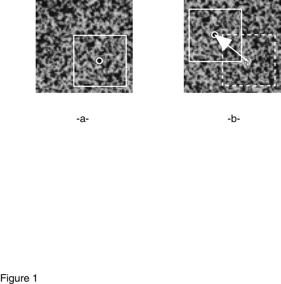
4 Second, the inception of localized phenomena can be monitored accurately (e.g., strain concentrations in composites, 21 necking in metals, 22 crack initiation in different materials 23 ). More generally, full-field measurements constitute an opportunity to bridge the gap between experiments and simulations allowing for comparisons between measured and computed displacement and strain fields. The aim of the paper is to show how the DIC technique can be used to validate a damage model in a multiaxial experiment for which the strain field is, by essence, heterogeneous. Section 2 is devoted to the presentation of the correlation technique used herein. The basic tools of the method are introduced. The algorithm is then discussed. Its performance is assessed with artificial 1D signals and 2D images. Section 3 deals with an application of the digital image correlation technique under multiaxial loading conditions. First, a damage model to be validated is introduced. The geometry of a specimen loaded in shear is designed by using the afore-mentioned damage model. The testing machine and its control system are presented. The performance of the technique is then evaluated in the shear experiment on a C/C composite material. A comparison between experiments and simulations by using the damage meso-model is performed. Two possible strategies are compared to couple displacement field measurements with finite element simulations. 2. DISPLACEMENT AND STRAIN FIELD MEASUREMENTS The displacement and strain fields are determined by digital image correlation. By using a CCD camera, pictures at different stages are recorded during the test. The specimen is usually coated by a random black and white pattern. Sometimes the natural texture of the observed surface is sufficient to use the technique with no coating. The in-plane displacement map is computed with a correlation technique between an initial picture and a subsequent one Preliminaries: Image Correlation One considers a sequence of sub-images (i.e., a square region) which will be referred to as zone of interest (ZOI). The aim of correlation method is to match the zone of interest in the two images (Fig. 1). The displacement of one ZOI with respect to the other one is a two-dimensional shift of an intensity signal digitized by a CCD camera. To estimate a shift between two images, 4
5 one of the standard approaches utilizes a correlation function. One considers signals g(ξ,ψ) which are merely perturbations of a shifted copy f(ξ δ x,ψ δ y ) of some reference signal f(ξ,ψ) g(ξ,ψ) = f(ξ δ x,ψ δ y ) + b(ξ,ψ) (1) where δ x, δ y are unknown displacements and b(ξ,ψ) a random noise. To evaluate the shift (δ x, δ y ), one may minimize the norm of the difference between f(ξ x,ψ y) and g(ξ,ψ) with respect to x and y min x,y g - f(. x,. y) 2. (2) where. denotes a dummy parameter. If one chooses the usual quadratic norm + + ( ) f 2 = f ξ,ψ dξ dψ, the previous minimization problem is equivalent to maximizing the quantity h(x,y) hx,y ( )= ( g f )x, y + + ( ) ( )= g ξ,ψ f ξ x, ψ y ( ) dξ dψ (3) where denotes the cross-correlation operator. Furthermore, when b is a white noise, the previous estimate is optimal. The computation of a cross-correlation can be performed either in the original space or in Fourier space, by using an FFT g f = FFT 1 (FFT[g] FFT[f] ) (4) where the complex conjugate is overlined. The use of the shifting property enables one to move a signal. For the sake of simplicity, let us consider the shift operator T d defined for 1D signals and defined by [T d f](ξ) = f(ξ d) (5) where d is the shift parameter. The FFT of T d f becomes FFT[ T d f] = E d FFT[f] (6) 5
6 where the modulation operator E d is defined by [E d f](ξ) = exp (-2π j d ξ) f(ξ) (7) These two results constitute the basic tools for image correlation Correlation Algorithm for Two-Dimensional Signals: CORRELI 2D Two images are considered. The first one, referred to as reference image and the second one, called deformed image. Figure 2 shows the algorithm explained below. One extracts the largest value p of a region of interest (ROI) of size 2 p x 2 p pixels centered in the reference image. The same ROI is considered in the deformed image. A first FFT correlation is performed to determine the average displacement U, V of the deformed image with respect to the reference image. This displacement is expressed in an integer number of pixels and is obtained as the maximum of the cross-correlation function evaluated for each pixel of the ROI. This first prediction enables one to determine the maximum number of pixels that belong to the two images. The ROI in the deformed image is now centered at a point corresponding to displaced center of the ROI in the reference image by an amount U, V. The user usually chooses the size of the zones of interest (ZOI) by setting the value of s < p so that the size is 2 s x 2 s pixels. To map the whole image, the second parameter to choose is the shift δx (= δy) between two consecutive ZOIs: 1 δx 2 s pixels. These two parameters define the mesh formed by the centers of each ZOI used to analyze the displacement field. The following analysis is performed for each ZOI independently. It follows that parallel computations can be used in the present case. A first FFT correlation is carried out and a first value of the inplane displacement correction U, V is obtained. The values U, V are again integer numbers so that the ZOI in the deformed image can be displaced by an additional amount U, V. The displacement residues are now less than 1/2 pixel in each direction. A sub-pixel iterative scheme can be used. To get good localization properties of the Fourier transform, the considered ZOI is then windowed by a modified Hanning window ZOI = ZOI (H H) (8) 6
7 where ZOI denotes the windowed ZOI, the dyadic product and H the one-dimensional modified Hanning window 1 4 π i 1 cos 2 2 s 1 Hi ()= π i 1 cos 2 2 s 1 when i 2 s-2 when 2 s-2 i 3 2 s-2 when 3 2 s-2 i 2 s 1 (9) The value 2 s 2 is an optimal value 24 to minimize the error due to edge effects and to have a sufficiently large number of data unaltered by the window. A cross-correlation is performed. A sub-pixel correction of the displacement δu, δv is obtained by determining the maximum of a parabolic interpolation of the correlation function. The interpolation is performed by considering the maximum pixel and its eight nearest neighbors. Therefore, one obtains a sub-pixel value. By using the shifting property of the Fourier transform, one can move the deformed ZOI by an amount δu, δv. Since an interpolation was used, one may induce some errors requiring to reiterate by considering the new deformed ZOI until a convergence criterion is reached. The criterion checks whether the maximum of the interpolated correlation function increases as the number of iteration increases. Otherwise, the iteration scheme is stopped. The procedure, 24 CORRELI 2D, is implemented in Matlab TM Performance of the Algorithm The first results are analyzed for 1D synthetic signals. A random pattern is generated (it is based on a Poisson Point Process for the center of segments of size equal to 5 pixels 24 ) and a second displaced signal is created with no noise (see Eqn. (2) with b=). However, digitization is accounted for and the whole scale is used. In many practical situations, CCD cameras produce 8- bit pictures. Some more sophisticated ones lead to 1-bit, 12-bit or even 16-bit codings. Let us first assume that the analyzed signal is 8-bit coded. Consequently, any displacement less than 2 8 pixel cannot be observed by an 8-bit camera (i.e., no grey level variation is obtained). Figure 3 shows the change in average relative error between a prescribed and measured displacement as a function of the prescribed displacement. Above the minimum observable value, the average 7
8 relative error is of the order of 3.5% for any value of the displacement. The minimum measurable displacements become smaller as the number of bits increases. Figure 3 illustrates this phenomenon. A lower bound is given by 2 b pixel, for a b-bit signal. Therefore, if the measurement of small displacements and strains is an issue, CCD cameras with high values of b are recommended. Furthermore, the variation of brightness and contrast may lead to an artificial change in coding. Instead of using the whole range of the coding, only a fraction is actually used. Consequently, the average error in displacement is digitization-independent (see Fig. 3). However, the minimum detectable displacement is strongly dependent upon the coding range. The previous results have a direct influence on the measurable strains. The strain measurement is performed by considering two adjacent centers of ZOI (a distance δx apart) and the displacement derivative is then evaluated. In that case, an estimate of the minimum measurable strain ε min (assumed to be constant over the gauge length) is directly related to the minimum detectable displacement increment u min for one fifth of the gauge length ε min 5 u min L (1) where L denotes the gauge length (i.e., the maximum distance between the centers of the ZOI). This result is consistent with numerical simulations for which values as low as 1 5 could be achieved when the gauge length was on the order of 1 pixels and 64 ZOI where analyzed 24 (s = 6, δx = 64 pixels). Equation (1) shows that to detect very small strains, one needs to increase the size of the gauge length, which may prevent one from detecting fluctuations or even discontinuities. A good compromise for 124-pixel signals is a 32- to 64-pixel long ZOI. For an 8-bit camera, these values are mainly indications of the general performances of the correlation algorithm. The procedure is now used with real images for which noise has to be considered (e.g., photon noise, readout noise, dark current or thermal noise 26 ) as well as digitization. Figure 4 shows the sub-pixel measurements obtained by the correlation technique. The C/C composite specimen to be introduced in Section 3.2 was used. The surface was sprayed by B/W paint to obtain a random texture (Fig. 1a). The sample was moved with a micrometric screw and the displacement was measured by an LVDT (maximum range: ±3 µm). Because of a mean absolute error less than 3/1-th pixel, 24 displacements less than the latter cannot be 8
9 measured accurately. This value has to be augmented by about 1/1-th pixel to account for digitization errors (since the full-scale of digitization is almost never achieved). It follows that the results of Fig. 4 are in agreement with the previous prediction. In the present case, displacements as small as 1µm can be measured with a very good accuracy, since the order of magnitude of the minimum displacement is.5µm. In Fig. 5, strain measurements by using strain gauges are compared with predictions of the correlation technique. Longitudinal and transverse strains are evaluated in a tensile test of a 224 aluminum alloy specimen. A special set-up is used to avoid spurious flexure A long-distance microscope is utilized to monitor a surface of 4mm 2. The average strain is computed over the total observed surface (i.e., 18 x 116 pixels). First, the displacement field is interpolated by cubic B-spline functions. The strain field is then derived and the average is computed. As expected, it is shown that a ZOI size of 64 pixels leads to better results than that with 32 pixels. The average absolute error is less than in the first case and in the second case. Strains as small as can be measured accurately in the first case and 1 4 in the second case. Furthermore, it can be noted that the average shear strains (negligibly small with the set-up) are found to be equal to and 1 5, respectively, with an average absolute error and , respectively. In Section 3.2, the same analysis will be performed when the strain field is heterogeneous. When a sequence of more than two images is analyzed, two routes can be followed. The first one consists in considering the same reference image. It follows that the errors are not cumulated but there exists a maximum strain level above which the method fails. For a ZOI of 64 pixels, the maximum observable strain is of the order of 5% for a 1 Mpixel image. The second one considers that the reference image is the deformed image of the previous step so that the displacements are added. Under these hypotheses, there is no real limitation, apart from the fact that the errors are now cumulated, and strains higher than 1% are routinely observed in a fullfield assessment USE OF FULL-FIELD MEASUREMENTS TO ANALYZE A MULTIAXIAL TEST The aim of this part is to validate a damage model by using a multiaxial test. Instead of assuming (perfect) boundary conditions, the displacement field measured by the DIC technique is used as an input for the FE simulations. 9
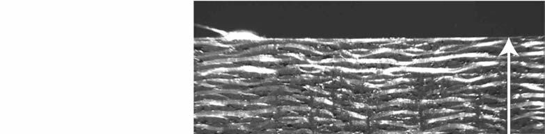
10 3.1. Damage Meso-Model A biaxial test is developed within the context of the modeling of the mechanical behavior of Multirex materials submitted to complex loading conditions. Multirex materials are carbon/carbon composites manufactured by SNECMA Engine Division. 29 Multirex preforms are either planar or axisymmetric. They are obtained by stacking either unidirectional plies or satin layers made of carbon yarns. Yarn fibers can be continuous or discontinuous. A needling process transfers some fibers along the third direction, perpendicular to the layer (Fig. 6a). These fiber reinforcements forbid delamination propagation. A Chemical Vapor Infiltration deposits the matrix in the preform made of discontinuous fibers. This type of material is specially designed for thermostructural applications such as brakes or structural parts of a rocket engine. The investigation concerning the thermomechanical behavior of a C/C composite focuses first on a series of uniaxial tension and compression tests in different directions on a [,9] n satin composite. These tests show an anisotropic behavior with damage and inelastic strains for tensile tests at and ±45. A different damage kinetics between tension and compression in both loading directions has been observed. 3 Constitutive equations based on an anisotropic damage model 31 written on a meso scale (i.e., that of a ply) is used to describe the main degradation mechanisms. 29,32 The model is based on the laminate theory and accounts for non linearities in each ply. Because the laminate thickness is negligible in comparison with other dimensions, a state of plane stress and a Kirchhoff-Love kinematics are assumed. Satin plies are modeled by a stacking of two orthogonal unidirectional elementary plies made of non-continuous fibers. For each ply, the degradation is assumed to be anisotropic and dictated by the fiber direction. Therefore, the damage meso-model is written in the ply coordinate system (1: fiber direction; 2: transverse direction). The elastic behavior of the i th ply can be written as e ε ˆ i = K ˆ 1 i σ ˆ i (11) with 1
11 ˆ σ i = σ 11 σ 22 2σ 12 e, ˆ ε i = e ε 11 e ε 22 e 2ε 12 1, K ˆ i = E 1 ν 12 E 1 ν 12 1 E 1 1 E 2 1 2G 12 (12) e where ε ˆ i is the elastic strain tensor in Voigt s notations, ˆ σ i the corresponding in-plane stress tensor, and ˆ K i the stiffness tensor expressed here as a function of the initial elastic properties of the material (denoted by the exponent ). For layers made of continuous fibers, the same framework has been used to model the mechanical behavior of laminates such as carbon/epoxy 29 or carbon/carbon 33 composites. For layers with non-continuous fibers, an additional damage variable (d 1 ) is introduced in the fiber direction to describe stiffness loss in that direction. 34 Such models are able to predict a degradation distribution for various configurations. 3 Damage kinetics is then described by using the elastic energy density of the damaged layer. For a plane stress state, this energy density E d can be written as E d = 1 2 σ E 1 1 d 1 ( ) + σ 11 2 σ E 1 E 2 1 d 2 ( ) + σ ν 12 σ E 2 E 11 σ G 12 2 σ 12 ( ) 1 d 12 (13) with f + = f if f, f + = otherwise f = f if f, f = otherwise (14) The damage variables (d 1, d 2, d 12 ) are assumed to be piecewise constant within the different plies. The difference between tensile and compressive behavior is caused by the opening and closure of micro-cracks. This aspect is accounted for by splitting the elastic energies into a 'tensile' energy (. + ) and a 'compressive' energy (. ). The kinetic laws of the damage variables d 1, d 12 et d 2 are written as 11
12 d 1 d 12 d 2 ( ) ()= t d 1 Y d1 (),Y τ d12 (),Y τ d 2 (),τ t τ ( ) ()= t d 12 Y d1 (),Y τ d12 (),Y τ d2 (),τ τ t ( ) ()= t d 2 Y d1 (),Y τ (),Y d12 τ (),τ τ t d2 (15) where Y d1, Y d12, Y d2 are the corresponding thermodynamic forces Y d1 Y d12 Y d2 = E d = d 1 σ = E d d 12 σ = = E d d 2 σ = 2 E 1 2 G 12 σ ( ) 2 1 d 1 ( σ 12 ) 2 ( ) 2 2 σ d 12 ( ) 2 2 E 2 1 d 2 (16) By following previous analyses, 29 the kinetic laws for transverse damage d 2 and shear damage d 12 are governed by the same coupled force Y d12 + by d2. Furthermore, the damage kinetics in the fiber direction d 1 is not coupled with transverse and shear damage d 1 d 12 d 2 ( ) if d 1 < 1, d 1 = 1 otherwise ( ()+ by d2 (),τ t τ ) if d 12 <1, d 12 =1 otherwise ( ()+ by d2 (), τ τ t) if d 2 < 1 and Y d 2 <Y d2 ()= t g' Y d1 (), τ τ t ()= t gy d12 τ ()= t b g Y d12 τ critical, d 2 = 1 otherwise (17) As a first approximation, the functions g and g are assumed to be linear when written in terms of the square root of the driving forces Y d1 and Y d12 + by d2, respectively g' ( Y)= Y Y 1 Y c 1 and g( Y)= Y Y (18) Y c The load history can be taken into account by using the following relationships 12
13 Y d1 Y d12 Y d2 ()= t sup τ t Y d1 () τ ()= t sup τ t Y d12 () τ ()= t sup τ t Y d 2 () τ (19) Inelastic strains on the ply level are assumed to be related to frictional phenomena. They are described by a plasticity model with isotropic hardening. The coupling between inelastic strains and damage is performed by using effective strains ε and stresses σ defined by with, Tr(σ.Ý ε p ) = Tr( σ. Ý ε p ) (2) σ 11 = σ 11 1 d 1 σ σ 12 = 12 1 d 12 σ 22 = σ 22 1 d 2 ( ) + σ 11 + ( ) ( ) + σ 22 + and Ý p Ý p Ý p ε 11 ε 12 ε 22 p = ε Ý 11 p = ε Ý 12 p = Ý ε 22 ( 1-d 1 ) σ 11 + σ 11 ( 1-d 12 ) ( 1-d 2 ) σ 22 + σ 22 σ p + Ý ε σ 11 σ p + ε Ý σ 22 (21) The yield surface is described by the following function f( σ,r) = a 11 2 σ a σ 22 + a σ 12 R(p) R (22) The plastic flow is given by ε Ý p 11 = a 2 σ 11 Ý p 11 R + R ε Ý p 12 = 1 2 a 2 σ Ý 12 p 12 R + R ε Ý p 2 22 = a 22 p Ý σ 22 R + R (23) where Ýp is the rate of cumulative plastic strain 2 p Ý = a 11 Ý p () ε a 12 Ý p () ε a 22 Ý p () ε 2 22 (24) 13
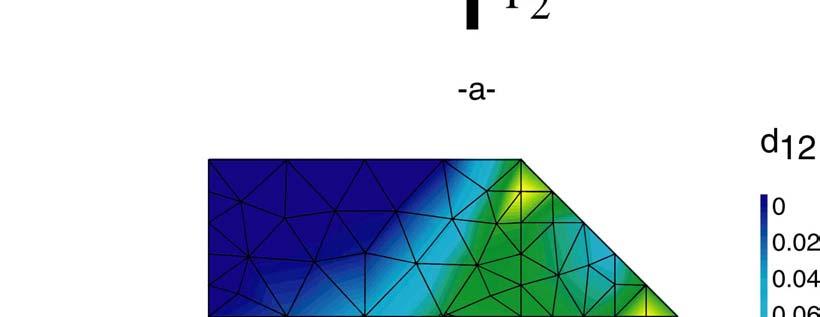
14 A complete identification requires loading the plies in various directions. However, the number of sequences available for the material is limited. Consequently, the identification is restricted to the more significant terms of the strain energy. 32 The identification is performed in two steps. First, elastic coefficients for both meso-constituents have been identified with tensile tests on a [,9] n hybrid composite made of both continuous and non-continuous fibers. Second, non-linear parameters have been identified thanks to tensile tests at and ±45 on a [,9] n satin composite made of non-continuous fibers. 3 For each test, several loading/unloading cycles are performed to evaluate the damage parameters (i.e., stiffness loss) and inelastic strains. An ad hoc identification strategy has been used to determine the whole set of material parameters. 35 The identified parameters are shown in Table 1 for a Multirex material. These parameters are implemented in a damage post-processor. 36 The input to the post-processor is the in-plane macroscopic strain tensor measured, by say a DIC technique, or the in-plane macroscopic stress tensor computed by a FE analysis. The Kirchhoff-Love kinematics yields strains or stresses on the ply level (i.e., meso level). The output is the dual macroscopic field (i.e., stress or strain, respectively) and the internal variables (e.g., damage) in each ply. The tensile tests performed on the [,9] n satin composite and used during the identification stage are simulated. Experimental and simulated strain/stress curves including various loading/unloading cycles are superimposed (Figure 7). The good agreement allows us to validate the tuning of the model parameters and the post-processor Shear Experiment on a C/C Composite The previous constitutive equations need to be validated with experimental results that have not been used in the identification stage. This is the role of the biaxial test discussed herein. This test is simulated with a 2D Finite Element (FE) analysis by using the above-mentioned constitutive equations and post-processor. Different degradation mechanisms are modeled by the three damage variables d 1, d 2 and d 12. Consequently, if this model is realistic, it should allow for the determination of the onset of overall failure by computing various damage fields: a damage localization usually corresponds to macro-crack initiation. Therefore, the comparison between FE simulations and experimental results enables us to test the predictive capacity of the model to describe crack initiation and to determine which mechanism led to crack initiation. 14
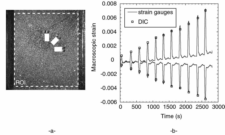
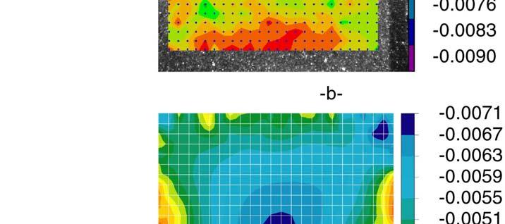
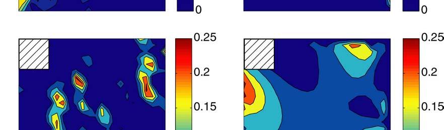
15 The test presented in this paper has been carried out on a multiaxial testing machine (ASTREE, see Fig. 8a). This testing machine has six servohydraulic actuators. Two vertical actuators, linked with the mobile crosshead and the base, respectively, have a load capacity of 25 kn and a stroke range of 25 mm. Four horizontal actuators have a load capacity of 1 kn and a stroke range of 25 mm. For protection purposes of the actuators at specimen failure (which can cause extremely high side and twist loads), additional hydraulic bearings are installed in front of each actuator. Closed loop control for each actuators is provided by a digital controller (Schenck 59 serial Hydropuls). The digital controller allows each actuator to be driven independently or in centroid mode. The centroid mode uses a relationship between two opposing actuators along the same axis to maintain the center of the specimen motionless. By ensuring that the center of the specimen and loading frame coincide, the user can prevent off-axis loadings that would damage the other actuators. Figure 8b illustrates how the centroid control algorithms work for a load-controlled test. For each axis pair (e.g., Y+ Y-), the controller uses the sum of the forces and the difference of the displacements along the considered axis. The performance of the centroid mode has been evaluated by using the DIC technique and a cross-shaped specimen. The results show that the centroid mode maintained the center of the specimen within ±1 µm from its initial position (i.e., less than 1 pixel in each direction). This centroid mode has been used in the multiaxial test presented hereafter. Tabs are glued on the face of each connecting arm of the specimen (Fig. 6b). The yarns are parallel to the bisectors of the loading directions. An a priori FE analysis of this geometry, using the above-mentioned damage model, shows that the shear damage field d 12 is confined in the central part of the specimen (Fig. 9). Because of the initial anisotropy of the material with respect to the loading axes, the central part of the specimen is the most loaded zone in terms of damage d 12 as well as strains. 32 Three strain gauges are glued on one face of the specimen, positioned at, 45 and 9, respectively (Fig. 1a). The strain field measurement is performed on the same face of the specimen. The specimen is maintained in the grips by 4 8 screws (Fig. 6b). For comparison purposes, the responses of two strain gauges (i.e., and 9 ) are considered. Figure 1b shows the gauge response and the average strain over the same active surface deduced from digital image correlation during the cyclic load history (Fig. 1c). A mean absolute error of 1-4 is obtained for this heterogeneous strain field. This result is consistent with the observations 15
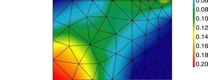
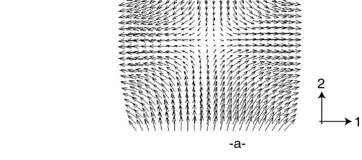
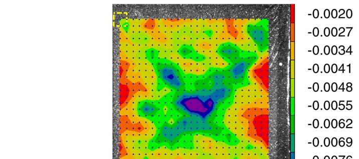
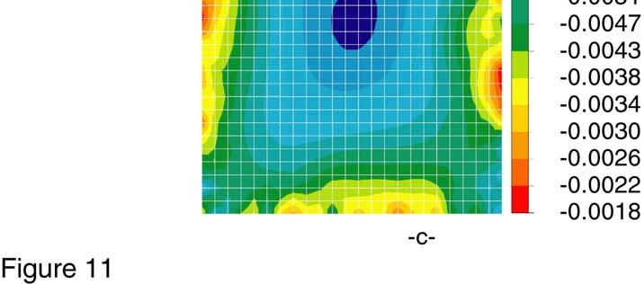
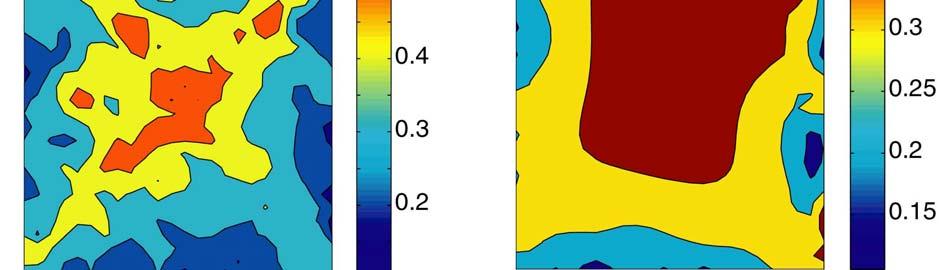
16 reported in Section 2.3. In the present case, it can be noted that, contrary to Section 2.3., the displacement and strain fields are not homogeneous. Figure 11a shows the displacement field on the surface of the specimen just before the failure of the specimen. One can note the good symmetry of the displacement field about the two loading directions Analysis of the Shear Experiment by the DIC Technique Coupled With FE Simulations To analyze the experimental results, two different approaches are developed. On the one hand, one uses all the experimental points within the ROI (i.e., all the centers of the ZOIs). The strain field is directly deduced from the measured displacement field by a numerical derivation. The damage post-processor is subsequently used to compute damage maps in the plies. On the other hand, one uses only the information on the boundary of the ROI. The displacements of these points are then used as boundary conditions for a FE computation. As a first approximation, an elastic (orthotropic) computation is performed and followed by a post-processing analysis to obtain the damage field. Figures 11b-c show the strain fields computed for the last image before failure. The strain field maps obtained by the two approaches are similar. Its symmetry with respect to the loading axes validates the quality of the applied loading. The extreme strain levels are comparable: the minimum is of the order of 1 2 and the maximum of the order of 1 3. This a posteriori result confirms the FE computations used to design this specimen geometry and the fact that the central part of the specimen plays a key role in this shear experiment. However, one can note that the strain field evaluated with the full-field displacement measurement is more heterogeneous than the one computed by using the measured displacement boundary conditions. This is a first indication that the material is not homogeneous on the scale of the measurements (of the order of 2-3 mm). It is worth remembering that the errors related to the correlation technique are negligible for strains of the order of 1 2. Therefore, it can be stated that the strain field fluctuations are induced by material imperfections. As mentioned earlier, the damage fields can be used to predict the onset of failure related to the degradations in both plies. The damage field inside each layer within the ROI is obtained by a computation by using the above-mentioned damage post-processor. Figure 12 shows shear damage fields (d 12 ) in the +45 and -45 plies. The fields obtained by the two approaches are again similar. As anticipated by the a priori computations (Fig. 9b), shear damage increases more in the central part of the specimen than near the edges. The damage field computed with the first 16
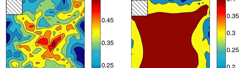
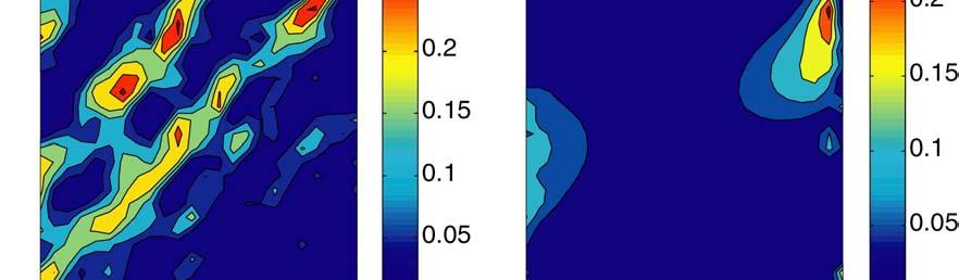
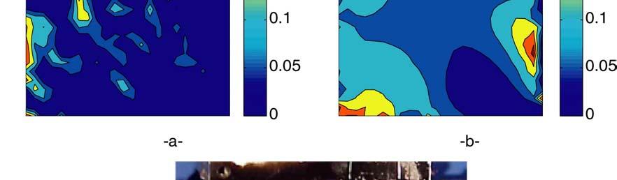
17 approach is more irregular. This field indicates a high degradation of the matrix, even more important (i.e.,.6) than that observed in a tensile test at ±45 (i.e.,.5). However, this damage field does not correspond to the actual failure pattern (Fig. 13c). Matrix damage is probably not the prevalent mechanism leading to the final failure of the specimen. To predict failure, the relevant variable to consider is damage in the fibers (d 1 ), i.e., fiber breakage is likely to be the mechanism responsible for the final failure. Figures 13a-b show the damage field for the two ply orientations. This time, the two approaches yield very different damage patterns. For the approach only using the measured boundary conditions, no significant degradation in the fiber directions is obtained within the ROI (i.e., <.25). On the contrary, for the full-field approach, it can be noted that the analysis of the damage contours in both ply directions can reproduce the overall failure pattern (Figures 13c). This failure pattern is induced by the anisotropy of the material, and fiber breakage caused by the undulations of the fiber (Fig. 6a) on the scale of the measurements. These results show that a damage meso-model is able to capture the overall failure pattern (i.e., damage maps in both ply directions) and to conclude that fibers in both directions are damaged at the inception of a macrocrack. It is also important to note that these conclusions can be drawn only thanks to a full-field strain measurement (on a macro scale) used as input to a post-processor to evaluate the damage variables on the ply level (i.e., on the meso scale). Therefore, this test constitutes a first validation of the damage model for a material on the scale of its use in practical applications. 4. CONCLUSIONS It has been shown that digital image correlation is a well-suited technique for mechanical investigations. In particular, no special preparation of the surface is needed except for some applications that require a coating by a random black and white pattern. In addition, the technique is not very sensitive to the illumination of the specimen. From both theoretical analyses and experimental comparisons with conventional strain gauges, the resolution of the technique is shown to be equal to for strains by using an 8-bit CCD camera. Interactions between experimental data and mechanical investigations are then discussed on the design of a shear experiment on a C/C composite material. The full displacement field has been considered in a numerical simulation to derive experimental strain field. A damage post- 17
18 processor has been applied to the experimental results to compute different damage fields. The approach is able to reproduce the observed failure pattern caused by fiber breakage in the experiment. A full-field assessment was needed to account for material heterogeneities on the scale of the observations. Even though the present technique is suitable for planar surfaces, it can be noted that it is also applicable to cylinders when the radius is not too small in comparison with the size of the region of interest. 37 The present digital image correlation technique was also used to monitor a high temperature thermomechanical experiment on aluminum tubes for which the texture was simply created by high temperature black and white paint. 38 Even higher temperatures can be reached by using black and white ceramic powders ACKNOWLEDGEMENTS The authors wish to acknowledge the help of Pierre Renaud the tensile tests on the aluminum alloy and Michel Coret for his assistance during the development of the DIC routine. The SNECMA Engine Division provided the Multirex C/C composite. 18
19 6. REFERENCES 1. Desrues, J., Lanier, J. and Stutz, P., Localization of the Deformation in Tests on Sand Sample, Engng. Fract. Mech., 21 (4), (1985). 2. Lagarde, A. (Ed.), Proc. IUTAM Symposium on Advanced Optical Methods and Applications in Solid Mechanics (Kluwer, the Netherlands), (2). 3. Humbert, L., Valle, V. and Cottron, M., Experimental Determination and Empirical Representation of Out-of-Plane Displacements in a Cracked Elastic Plate Loaded in Mode I, Int. J. Solids Struct., 37, (2). 4. Sutton, M.A., McNeill, S.R., Helm, J.D. and Chao, Y.J., Advances in Two-Dimensional and Three-Dimensional Computer Vision, in Photomechanics, P.K. Rastogi (Ed.), Topics in Appl. Phys., 77, (2). 5. Roux, S., Hild, F. and Berthaud, Y., Correlation Image Velocimetry: A Spectral Approach, Appl. Optics (21), in press. 6. Choi, D., Thorpe, J.L. and Hanna, R., Image Analysis to Measure Strain in Wood and Paper, Wood Sci. Technol., 25, (1991). 7. G'Sell, C., Hiver, J.-M., Dahnoun, A. and Souahi, A., Video-Controlled Tensile Testing of Polymers and Metals Beyond the Necking Point, J. Mat. Sci., 27, (1992). 8. Chevalier, L., Calloch, S., Hild, F. and Marco, Y., Digital Correlation used to Analyze the Multiaxial Behavior of Rubber-like Materials, Eur. J. Mech. A/Solids, 2, (21). 9. Dudderar, T.D. and Simpkins, P.G., Laser Speckle Photography in a Fluid Medium, Nature 27, 45 (1977). 1. Pickering, C.J.D. and Halliwell, N.A., Speckle Laser in Fluid Flows: Signal Recovery with Two-Step Processing, Appl. Opt., 23, 1129 (1984). 11. Merzkirch, W., Flow Visualization (Academic, New York, USA) (1987). 12. Rastogi, P.K. (Ed.), Photomechanics, Topics in Appl. Phys., 77, Springer, Berlin (Germany) (2). 13. Chiang, F.P. (Ed.), Coherent Optical Technique and Experimental Mechanics, Opt. Eng., 21 (3) (1982). 19
20 14. Sutton, M.A., Wolters, W.J., Peters, W.H., Ranson, W.F. and McNeill, S.R., Determination of Displacements Using an Improved Digital Correlation Method, Im. Vis. Comp., 1 (3), (1983). 15. Chu, T.C., Ranson, W.F., Sutton, M.A. and Petters, W.H., Applications of Digital-Image- Correlation Techniques to Experimental Mechanics, EXPERIMENTAL MECHANICS, 3, (1985). 16. Mguil, S., Morestin, F. and Brunet, M., Mesure des déformations par corrélation directe d'images numériques, Proc. Photomécanique 98, Berthaud, Y., Cottron, M., Morestin, F., Moucheront, P. and Taroni, M. (Eds.), GAMAC, Marne-la-Vallée (France), (1998), in French. 17. Chen, D.J., Chiang, F.P., Tan, Y.S. and Don, H.S., Digital Speckle-Displacement Measurement Using a Complex Spectrum Method, Appl. Opt., 32, 1839 (1993). 18. Berthaud, Y., Scholz, J. and Thesing, J., Méthodes optiques et acoustiques de mesures des caractéristiques mécaniques, Proc. Colloque national MECAMAT Mécanismes et mécanique des grandes déformations, Aussois (France), 77 8 (1996), in French. 19. Chiang, F.P., Wang, Q. and Lehman, F., New Developments in Full-Field Strain Measurements Using Speckles, ASTM STP 1318, 156 (1997). 2. Bouvet, C., Calloch, S. and Lexcellent, C., Mechanical Behavior of a Cu-Al-Be Shape Memory Alloy under Multiaxial Proportional and Nonproportional Loadings, J. Eng. Mat. Tech., submitted, (21). 21. Berthaud, Y., Calloch, S., Collin, F., Hild, F. and Ricotti, Y., Analysis of the Degradation Mechanisms in Composite Materials through a Correlation Technique in White Light, IUTAM symposium on Advanced Optical Methods and Applications in Solid Mechanics, Lagarde, A. (Ed.), Kluwer (the Netherlands), (2). 22. Wattrisse, B., Chrysochoos, A., Muracciole, J.-M. and Némoz-Gaillard, M., Analysis of Strain Localization during Tensile Tests by Digital Image Correlation, EXPERIMENTAL MECHANICS, (21). 23. Berthaud, Y., Calloch, S., Cluzel, C., Hild, F. and Périé, J.-N., Experiment / Computation Interactions by using Digital Image Correlation, Interferometry in Speckle light, Theory and Applications, Jacquot, P. and Fournier, J.-M. (Eds.), Springer, Berlin (Germany), (2) 2
21 24. Hild, F., Périé, J.-N. and Coret, M., Mesure de champs de déplacements 2D par intercorrélation d'images : CORRELI 2D, internal report (LMT-Cachan), 23 (1999) in French. 25. Matlab 5.3, The MathWorks, inc. ( (1999). 26. Young, I.T., Gerbrands, J.J. and van Vliet, L.J., Image Processing Fundamentals, (1999). 27. Hild, F., Dispositif de traction-compression d une éprouvette. ENS de Cachan / Renault, French patent no (Bulletin Officiel de la propriété industrielle, 92/33 14 août 1992, n de publication ), June 1 st, (199). 28. Hild, F., Amar, E. and Marquis, D., Stress Heterogeneity Effect on the Strength of Silicon Nitride, J. Am. Ceram. Soc., 75 (3), 7 72 (1992). 29. Ladevèze, P. and Ledantec, E., A Damage Modelling of the Elementary Ply for Laminated Composites, Comp. Sci. Tech., 43, (1992). 3. Périé, J.-N., Aubard, X., Cluzel, C. and Ladevèze, P., Méso-modélisation des mécanismes d endommagement d une famille de matériaux Sepcarb à textures multidirectionnelles, Proc. JNC11, AMAC, (1998) in French. 31. Ladevèze, P., sur la mécanique de l endommagement des composites, Proc. JNC 5, Bathias, C. and Menkès, D. (Eds.), Pluralis Publication, Paris (France), (1986) in French. 32. Périé, J.-N., Méso-modélisation des mécanismes d'endommagement dans les composites C/C à texture multidirectionnelle, PhD dissertation, ENS de Cachan (2) in French. 33. Ladevèze, P., Allix, O. and Cluzel, C., Damage modelling at the macro and meso scales for 3D composites, Damage in Composite Materials, Voyiadjis, G. Z. (Ed.), Elsevier, (1993). 34. Gasser, A., Ladevèze, P. and Peres, P., Damage modelling for a laminated ceramic composite, Mat. Sci. Eng., A25, (1998). 35. Aubard, X., Cluzel, C., Ladevèze, P. and Périé, J.-N., Méso-modélisation des matériaux composites carbone/carbone à texture Multirex, Proc. 3 e colloque national en calcul des structures, (1997) in French. 36. Cluzel, C., DAMLAM : un outil simplifié pour l'analyse de composites stratifiés, Proc. JNC12, AMAC, (2) in French. 21
22 37. Lu, H., Vendroux, G. and Knauss, G., Surface Deformation Measurements of a Cylindrical Specimen by Digital Image Correlation, EXPERIMENTAL MECHANICS, (1997). 38. Pommier, B., Charkaluk, E. and Hild, F., Analyse d'un essai de fatigue thermique par corrélation d'images, Proc. Photomécanique 21, Berthaud, Y., Cottron, M., Dupré, J.-C., Morestin, F., Orteu, J.-J. and Valle, V. (Eds.), (21) in French. 22
23 FIGURE CAPTIONS Figure 1: ZOI in the initial (a) and deformed (b) image. Figure 2: flowchart of the sub-pixel correlation algorithm. Figure 3: Average relative error between measured and prescribed displacements vs. prescribed displacement for different digitizations of an artificial 1D signal. Figure 4: Measured vs. prescribed displacement for an 8-bit camera. The reference image is shown in Fig. 1a. Figure 5: Strains measured by gauges and predicted by digital image correlation (DIC) with two ZOI sizes in a tensile test on an aluminum specimen loaded in tension. Figure 6: View of the material microstructure (a) and a shear experiment on a composite plate (b). Figure 7: Predicted (dashed line) versus experimental (solid line) stress/strain curves for tensile tests on a C/C composite at (a) and ±45 (b). Figure 8: Multiaxial testing machine ASTREE (a) and schematic of the centroid control system for one axis (b). Figure 9: Schematic of the shear experiment (a) and shear damage contours in one quarter of either ply of the specimen (b). Figure 1: Location of the strain gauges (white rectangles) and region of interest for the DIC analysis (a), comparison between two gauge responses and measurements by the DIC technique (b), load history (c) in a shear experiment on a C/C composite. Figure 11: Displacement map prior to failure (a). An amplification factor of 3 is used for the inplane displacement vectors. Strain ε 22 maps deduced from: (b) a full-field displacement 23
24 measurement and a direct strain derivation, (c) the measured boundary conditions and an elastic computation. Figure 12: Matrix damage contours d 12 in both ply directions predicted by the damage postprocessor using strains deduced from: (a) a full-field displacement measurement and a direct derivation, (b) the measured boundary conditions and an elastic computation. Figure 13: Fiber damage contours d 1 in both ply directions predicted by the damage postprocessor using strains deduced from: (a) a full-field displacement measurement and a direct derivation, (b) the measured boundary conditions and an elastic computation. Final failure pattern (c). 24
25 25
26 26
27 27
28 28
29 29
30 3
31 31
32 32

33 33
34 34
35 35
36 36

37 37
38 38
39 TABLE CAPTION Table 1: Material parameters of the damage model at room temperature for a C/C composite. 39
40 Table 1 E 1 E 2 G 12 ν 12 b Y Y c Y 1 Y c1 52 GPa 16.7 GPa 6.9 GPa kpa.59 MPa 4.1 kpa 1.64 MPa a 11 a 12 a 22 γ β R MPa 4
DAMAGE MODELLING OF A SATIN SEPCARB COMPOSITE
 DAMAGE MODELLING OF A SATIN SEPCARB COMPOSITE X. Aubard 1, C. Cluzel 2,3, P. Ladevèze 2 and J.N. Périé 2 1 SEP Division de SNECMA, Le Haillan BP 37, 33165 St MEDARD-EN-JALLES, FRANCE 2 LMT Cachan, E.N.S.
Digital Image Correlation used to Analyze the Multiaxial Behavior of Rubber-like Materials
 To appear in the European Journal of Mechanics A/Solids Digital Image Correlation used to Analyze the Multiaxial Behavior of Rubber-like Materials by L. Chevalier, S. Calloch, F. Hild and Y. Marco LMT-Cachan
MODELING OF THE BEHAVIOR OF WOVEN LAMINATED COMPOSITES UNTIL RUPTURE
 MODELING OF THE BEHAVIOR OF WOVEN LAMINATED COMPOSITES UNTIL RUPTURE Jean Paul Charles, Christian Hochard,3, Pierre Antoine Aubourg,3 Eurocopter, 375 Marignane cedex, France Unimeca, 6 rue J. Curie, 3453
Tools for Multiaxial Validation of Behavior Laws Chosen for Modeling Hyper-elasticity of Rubber-like Materials
 This is an uncorrected proof of an article published in JPES. Please cite this reference: CHEVALIER L., MARCO Y., Tools for multiaxial validation of behavior laws chosen for modeling hyper-elasticity of
Material Characterization of Carbon Fiber Reinforced Polymer Laminate Using Virtual Fields Method
 Proceedings of ICTACEM 014 International Conference on Theoretical, Applied, Computational and Experimental Mechanics December 9-31, 014, IIT Kharagpur, India ICTACEM-014/39 Material Characterization of
BIAXIAL STRENGTH INVESTIGATION OF CFRP COMPOSITE LAMINATES BY USING CRUCIFORM SPECIMENS
 BIAXIAL STRENGTH INVESTIGATION OF CFRP COMPOSITE LAMINATES BY USING CRUCIFORM SPECIMENS H. Kumazawa and T. Takatoya Airframes and Structures Group, Japan Aerospace Exploration Agency 6-13-1, Ohsawa, Mitaka,
Tensile behaviour of anti-symmetric CFRP composite
 Available online at www.sciencedirect.com Procedia Engineering 1 (211) 1865 187 ICM11 Tensile behaviour of anti-symmetric CFRP composite K. J. Wong a,b, *, X. J. Gong a, S. Aivazzadeh a, M. N. Tamin b
Mechanical modelling of SiC/SiC composites and design criteria
 Mechanical modelling of SiC/SiC composites and design criteria F. Bernachy CEA, DEN/DMN/SRMA/LC2M, Gif-sur-Yvette, France L. Gélébart CEA, DEN/DMN/SRMA/LC2M, Gif-sur-Yvette, France J. Crépin Centre des
Open-hole compressive strength prediction of CFRP composite laminates
 Open-hole compressive strength prediction of CFRP composite laminates O. İnal 1, A. Ataş 2,* 1 Department of Mechanical Engineering, Balikesir University, Balikesir, 10145, Turkey, inal@balikesir.edu.tr
Plane Strain Test for Metal Sheet Characterization
 Plane Strain Test for Metal Sheet Characterization Paulo Flores 1, Felix Bonnet 2 and Anne-Marie Habraken 3 1 DIM, University of Concepción, Edmundo Larenas 270, Concepción, Chile 2 ENS - Cachan, Avenue
Multiscale analyses of the behaviour and damage of composite materials
 Multiscale analyses of the behaviour and damage of composite materials Presented by Didier BAPTISTE ENSAM, LIM, UMR CNRS 8006 151 boulevard de l hôpital l 75013 PARIS, France Research works from: K.Derrien,
TOWARD VIRTUAL CERAMIC COMPOSITES
 TOWARD VIRTUAL CERAMIC COMPOSITES M. Genet 1, P. Ladevèze 12, G. Lubineau 1 1 LMT-Cachan (ENS-Cachan, CNRS, Paris 6 University, UniverSud Paris PRES) 61 avenue du Président Wilson 94235 Cachan CEDEX {genet,
Module III - Macro-mechanics of Lamina. Lecture 23. Macro-Mechanics of Lamina
 Module III - Macro-mechanics of Lamina Lecture 23 Macro-Mechanics of Lamina For better understanding of the macromechanics of lamina, the knowledge of the material properties in essential. Therefore, the
Nigerian Journal of Technology, Vol. 26, No. 2, June 2007 Edelugo 37
 Nigerian Journal of Technology, Vol. 26, No. 2, June 2007 Edelugo 37 APPLICATION OF THE REISSNERS PLATE THEORY IN THE DELAMINATION ANALYSIS OF A THREE-DIMENSIONAL, TIME- DEPENDENT, NON-LINEAR, UNI-DIRECTIONAL
Shock enhancement of cellular structures under impact loading: Part II Analysis
 Shock enhancement of cellular structures under impact loading: Part II Analysis S. Pattofatto, 1 I. Elnasri, 1 H. Zhao, 1* H. Tsitsiris 1 F. Hild 1 and Y. Girard 2 1 Laboratoire de Mécanique et Technologie
DIGITAL IMAGE CORRELATION APPLIED TO THERMAL EXPANSION OF COMPOSITES
 DIGITAL IMAGE CORRELATION APPLIED TO THERMAL EXPANSION OF COMPOSITES C. Flament 1,2 *, M. Salvia 1 *, B. Berthel 1, G. Crosland 2 1 LTDS, UMR5513, Ecully, France, 2 Valeo Matériau de Friction, Limoges,
Lecture #8: Ductile Fracture (Theory & Experiments)
") Lecture #8: Ductile Fracture (Theory & Experiments) by Dirk Mohr ETH Zurich, Department of Mechanical and Process Engineering, Chair of Computational Modeling of Materials in Manufacturing 2015 1 1 1 Ductile
Lecture #8: Ductile Fracture (Theory & Experiments) by Dirk Mohr ETH Zurich, Department of Mechanical and Process Engineering, Chair of Computational Modeling of Materials in Manufacturing 2015 1 1 1 Ductile
Analysis of nonlinear shear deformations in CFRP and GFRP textile laminates
 Loughborough University Institutional Repository Analysis of nonlinear shear deformations in CFRP and GFRP textile laminates This item was submitted to Loughborough University's Institutional Repository
A novel approach to predict the growth rate of short cracks under multiaxial loadings
 A novel approach to predict the growth rate of short cracks under multiaxial loadings F. Brugier 1&2, S. Pommier 1, R. de Moura Pinho 2, C. Mary 2 and D. Soria 2 1 LMT-Cachan, ENS Cachan / CNRS / UPMC
Modelling the nonlinear shear stress-strain response of glass fibrereinforced composites. Part II: Model development and finite element simulations
 Modelling the nonlinear shear stress-strain response of glass fibrereinforced composites. Part II: Model development and finite element simulations W. Van Paepegem *, I. De Baere and J. Degrieck Ghent
An investigation of the mechanical behaviour of carbon epoxy cross ply cruciform specimens under biaxial loading
 An investigation of the mechanical behaviour of carbon epoxy cross ply cruciform specimens under biaxial loading A. Makris, C. Ramault, D. Van Hemelrijck Department of Mechanics of Materials and Constructions,
A TIME-DEPENDENT DAMAGE LAW IN DEFORMABLE SOLID: A HOMOGENIZATION APPROACH
 9th HSTAM International Congress on Mechanics Limassol, Cyprus, - July, A TIME-DEPENDENT DAMAGE LAW IN DEFORMABLE SOLID: A HOMOGENIZATION APPROACH Cristian Dascalu, Bertrand François, Laboratoire Sols
IMPACT ON LAMINATED COMPOSITE PLATES: COMPARISON OF TEST AND SIMULATION RESULTS OBTAINED WITH LMS SAMTECH SAMCEF
 V ECCOMAS Thematic Conference on the Mechanical Response of Composites COMPOSITES 015 S.R. Hallett and J.J.C. Remmers (Editors) IMPACT ON LAMINATED COMPOSITE PLATES: COMPARISON OF TEST AND SIMULATION RESULTS
A MULTISCALE DAMAGE MODEL FOR THE ANALYSIS OF LAMINATED COMPOSITE STRUCTURES ON THE MICROSCALE
 A MULTISCALE DAMAGE MODEL FOR THE ANALYSIS OF LAMINATED COMPOSITE STRUCTURES ON THE MICROSCALE P. Ladevèze 1,2, M. Trovalet 1, G. Lubineau 1 1 LMT-Cachan (ENS Cachan/CNRS/UPMC/Pres Universud Paris) 61
Multi Disciplinary Delamination Studies In Frp Composites Using 3d Finite Element Analysis Mohan Rentala
 Multi Disciplinary Delamination Studies In Frp Composites Using 3d Finite Element Analysis Mohan Rentala Abstract: FRP laminated composites have been extensively used in Aerospace and allied industries
Damage law identification of a quasi brittle ceramic from a bending test using digital image correlation
 EPJ Web of Conferences 6, 6 3 () DOI:.5/epjconf/63 Owned by the authors, published by EDP Sciences, Damage law identification of a quasi brittle ceramic from a bending test using digital image correlation
Impact and Crash Modeling of Composite Structures: A Challenge for Damage Mechanics
 Impact and Crash Modeling of Composite Structures: A Challenge for Damage Mechanics Dr. A. Johnson DLR Dr. A. K. Pickett ESI GmbH EURO-PAM 99 Impact and Crash Modelling of Composite Structures: A Challenge
Application of Regularized Digital Images Correlation Analysis to the Tensile Test of NiTi Shape Memory Alloy
 Application of Regularized Digital Images Correlation Analysis to the Tensile Test of NiTi Shape Memory Alloy Xuyang Chang, Mame Daro Fall, Karine Lavernhe Taillard, Olivier Hubert To cite this version:
Strength of GRP-laminates with multiple fragment damages
 Strength of GRP-laminates with multiple fragment damages S. Kazemahvazi, J. Kiele, D. Zenkert Kungliga Tekniska Högskolan, KTH 100 44 Stockholm, Sweden sohrabk@kth.se SUMMARY The strength of glass fibre
Non-conventional Glass fiber NCF composites with thermoset and thermoplastic matrices. F Talence, France Le Cheylard, France
 20 th International Conference on Composite Materials Copenhagen, 19-24th July 2015 Non-conventional Glass fiber NCF composites with thermoset and thermoplastic matrices. Thierry Lorriot 1, Jalal El Yagoubi
Evaluation of in-plane orthotropic elastic constants of paper and paperboard
 Evaluation of in-plane orthotropic elastic constants of paper and paperboard T. Yokoyama and K. Nakai Department of Mechanical Engineering, Okayama University of Science - Ridai-cho, Okayama 7-5, Japan
FINITE ELEMENT ANALYSIS OF COMPOSITE MATERIALS
 FINITE ELEMENT ANALYSIS OF COMPOSITE MATERIALS Ever J. Barbero Department of Mechanical and Aerospace Engineering West Virginia University USA CRC Press Taylor &.Francis Group Boca Raton London New York
Identification of the plastic zone using digital image correlation
 M. Rossi et alii, Frattura ed Integrità Strutturale, 3 (4) 55-557; DOI:.3/IGF-ESIS.3.66 Focussed on: Fracture and Structural Integrity related Issues Identification of the plastic zone using digital image
Progressive Damage of GFRP Composite Plate Under Ballistic Impact: Experimental and Numerical Study
 Progressive Damage of GFRP Composite Plate Under Ballistic Impact: Experimental and Numerical Study Progressive Damage of GFRP Composite Plate Under Ballistic Impact: Experimental and Numerical Study Md
Failure analysis of serial pinned joints in composite materials
 Indian Journal of Engineering & Materials Sciences Vol. 18, April 2011, pp. 102-110 Failure analysis of serial pinned joints in composite materials Alaattin Aktaş* Department of Mechanical Engineering,
Coupling of plasticity and damage in glass fibre reinforced polymer composites
 EPJ Web of Conferences 6, 48 1) DOI: 1.151/epjconf/1648 c Owned by the authors, published by EDP Sciences, 1 Coupling of plasticity and damage in glass fibre reinforced polymer composites R. Kvale Joki
LAMINATION THEORY FOR THE STRENGTH OF FIBER COMPOSITE MATERIALS
 XXII. LAMINATION THEORY FOR THE STRENGTH OF FIBER COMPOSITE MATERIALS Introduction The lamination theory for the elastic stiffness of fiber composite materials is the backbone of the entire field, it holds
Crash and Impact Simulation of Composite Structures by Using CAE Process Chain
 Crash and Impact Simulation of Composite Structures by Using CAE Process Chain Madhukar Chatiri 1, Thorsten Schütz 2, Anton Matzenmiller 3, Ulrich Stelzmann 1 1 CADFEM GmbH, Grafing/Munich, Germany, mchatiri@cadfem.de
Lecture #2: Split Hopkinson Bar Systems
 Lecture #2: Split Hopkinson Bar Systems by Dirk Mohr ETH Zurich, Department of Mechanical and Process Engineering, Chair of Computational Modeling of Materials in Manufacturing 2015 1 1 1 Uniaxial Compression
Digital Image Correlation and biaxial test on composite material for anisotropic damage law identification
 Digital Image Correlation and biaxial test on composite material for anisotropic damage law identification Jean-Noël Périé, Hugo Leclerc, Stéphane Roux, François Hild To cite this version: Jean-Noël Périé,
Mech Eng Dept, University of Bristol, UK
 Advanced Materials Research Online: 214-8-11 ISSN: 12-885, Vol., pp 24-255 doi:1.428/www.scientific.net/amr..24 214 Trans Tech Publications, Switzerland Plasticity and stress heterogeneity influence on
A Performance Modeling Strategy based on Multifiber Beams to Estimate Crack Openings ESTIMATE in Concrete Structures CRACK
 A Performance Modeling Strategy based on Multifiber Beams to Estimate Crack Openings ESTIMATE in Concrete Structures CRACK A. Medjahed, M. Matallah, S. Ghezali, M. Djafour RiSAM, RisK Assessment and Management,
A FINITE ELEMENT MODEL TO PREDICT MULTI- AXIAL STRESS-STRAIN RESPONSE OF CERAMIC MATRIX COMPOSITES WITH STRAIN INDUCED DAMAGE
 A FINITE ELEMENT MODEL TO PREDICT MULTI- AXIAL STRESS-STRAIN RESPONSE OF CERAMIC MATRIX COMPOSITES WITH STRAIN INDUCED DAMAGE Daxu Zhang and D. R. Hayhurst School of Mechanical, Aerospace and Civil Engineering,
SIZE EFFECTS IN THE COMPRESSIVE CRUSHING OF HONEYCOMBS
 43rd AIAA/ASME/ASCE/AHS/ASC Structures, Structural Dynamics, and Materials Con 22-25 April 2002, Denver, Colorado SIZE EFFECTS IN THE COMPRESSIVE CRUSHING OF HONEYCOMBS Erik C. Mellquistand Anthony M.
Fracture Mechanics of Composites with Residual Thermal Stresses
 J. A. Nairn Material Science & Engineering, University of Utah, Salt Lake City, Utah 84 Fracture Mechanics of Composites with Residual Thermal Stresses The problem of calculating the energy release rate
THE MUTUAL EFFECTS OF SHEAR AND TRANSVERSE DAMAGE IN POLYMERIC COMPOSITES
 THE 19 TH INTERNATIONAL CONFERENCE ON COMPOSITE MATERIALS THE MUTUAL EFFECTS OF SHEAR AND TRANSVERSE DAMAGE IN POLYMERIC COMPOSITES L.V. Smith 1 *, M. Salavatian 1 1 School of Mechanical and Materials
A rate-dependent Hosford-Coulomb model for predicting ductile fracture at high strain rates
 EPJ Web of Conferences 94, 01080 (2015) DOI: 10.1051/epjconf/20159401080 c Owned by the authors, published by EDP Sciences, 2015 A rate-dependent Hosford-Coulomb model for predicting ductile fracture at
INTERNATIONAL JOURNAL OF APPLIED ENGINEERING RESEARCH, DINDIGUL Volume 2, No 1, 2011
 Interlaminar failure analysis of FRP cross ply laminate with elliptical cutout Venkateswara Rao.S 1, Sd. Abdul Kalam 1, Srilakshmi.S 1, Bala Krishna Murthy.V 2 1 Mechanical Engineering Department, P. V.
ISSN: ISO 9001:2008 Certified International Journal of Engineering Science and Innovative Technology (IJESIT) Volume 2, Issue 4, July 2013
 Volume 2, Issue 4, July 2013") Delamination Studies in Fibre-Reinforced Polymer Composites K.Kantha Rao, Dr P. Shailesh, K. Vijay Kumar 1 Associate Professor, Narasimha Reddy Engineering College Hyderabad. 2 Professor, St. Peter s Engineering
Delamination Studies in Fibre-Reinforced Polymer Composites K.Kantha Rao, Dr P. Shailesh, K. Vijay Kumar 1 Associate Professor, Narasimha Reddy Engineering College Hyderabad. 2 Professor, St. Peter s Engineering
A RESEARCH ON NONLINEAR STABILITY AND FAILURE OF THIN- WALLED COMPOSITE COLUMNS WITH OPEN CROSS-SECTION
 A RESEARCH ON NONLINEAR STABILITY AND FAILURE OF THIN- WALLED COMPOSITE COLUMNS WITH OPEN CROSS-SECTION H. Debski a*, J. Bienias b, P. Jakubczak b a Faculty of Mechanical Engineering, Department of Machine
ADVANCES IN THE PROGRESSIVE DAMAGE ANALYSIS OF COMPOSITES
 NAFEMS WORLD CONGRESS 13, SALZBURG, AUSTRIA ADVANCES IN THE PROGRESSIVE DAMAGE ANALYSIS OF M. Bruyneel, J.P. Delsemme, P. Jetteur (LMS Samtech, Belgium); A.C. Goupil (ISMANS, France). Dr. Ir. M. Bruyneel,
THE ROLE OF DELAMINATION IN NOTCHED AND UNNOTCHED TENSILE STRENGTH
 THE ROLE OF DELAMINATION IN NOTCHED AND UNNOTCHED TENSILE STRENGTH M. R. Wisnom University of Bristol Advanced Composites Centre for Innovation and Science University Walk, Bristol BS8 1TR, UK M.Wisnom@bristol.ac.uk
Computational Analysis for Composites
 Computational Analysis for Composites Professor Johann Sienz and Dr. Tony Murmu Swansea University July, 011 The topics covered include: OUTLINE Overview of composites and their applications Micromechanics
USE OF DIGITAL IMAGE CORRELATION TO OBTAIN MATERIAL MODEL PARAMETERS FOR COMPOSITES
 USE OF DIGITAL IMAGE CORRELATION TO OBTAIN MATERIAL MODEL PARAMETERS FOR COMPOSITES Brian Croop, Hubert Lobo (DatapointLabs, USA). Presenter: Hubert Lobo, President SUMMARY The development of material
1.103 CIVIL ENGINEERING MATERIALS LABORATORY (1-2-3) Dr. J.T. Germaine Spring 2004 LABORATORY ASSIGNMENT NUMBER 6
 Dr. J.T. Germaine Spring 2004 LABORATORY ASSIGNMENT NUMBER 6") 1.103 CIVIL ENGINEERING MATERIALS LABORATORY (1-2-3) Dr. J.T. Germaine MIT Spring 2004 LABORATORY ASSIGNMENT NUMBER 6 COMPRESSION TESTING AND ANISOTROPY OF WOOD Purpose: Reading: During this laboratory
1.103 CIVIL ENGINEERING MATERIALS LABORATORY (1-2-3) Dr. J.T. Germaine MIT Spring 2004 LABORATORY ASSIGNMENT NUMBER 6 COMPRESSION TESTING AND ANISOTROPY OF WOOD Purpose: Reading: During this laboratory
Domain optimisation using Trefftz functions application to free boundaries
 Computer Assisted Mechanics and Engineering Sciences, 4: 317 326, 1997. Copyright c 1997 by Polska Akademia Nauk Domain optimisation using Trefftz functions application to free boundaries Mohamed Bouberbachene,
On the micro- and mesomodeling of the interfaces between laminate plies
 On the micro- and mesomodeling of the interfaces between laminate plies P.Ladevèze*, D.Marsal*, G.Lubineau* *LMT-Cachan, E.N.S. Cachan / Université Paris 6 / C.N.R.S. 61 Avenue du Président Wilson, 94235
EXPERIMENTAL STUDY OF IMPACTS ON HELICOPTER BLADES USING DIGITAL IMAGE CORRELATION
 THE 19 TH INTERNATIONAL CONFERENCE ON COMPOSITE MATERIALS EXPERIMENTAL STUDY OF IMPACTS ON HELICOPTER BLADES USING DIGITAL IMAGE CORRELATION J.C. Passieux 1, P. Navarro* 1, J. Aubry 1, S. Marguet 1, J.F.
Multi-scale digital image correlation of strain localization
 Multi-scale digital image correlation of strain localization J. Marty a, J. Réthoré a, A. Combescure a a. Laboratoire de Mécanique des Contacts et des Strcutures, INSA Lyon / UMR CNRS 5259 2 Avenue des
FRACTURE IN PBX 9501 AT LOW RATES
 FRACTURE IN PBX 9501 AT LOW RATES Cheng Liu & Richard Browning Los Alamos National Laboratory Los Alamos, NM 87545 Tensile, or mode I, fractures in PBX 9501 have a very large process zone that runs well
A Portable Optical DSPI System for Residual Stresses Measurement by Hole Drilling Using the Integral Method in Terms of Displacement
 A Portable Optical DSPI System for Residual Stresses Measurement by Hole Drilling Using the Integral Method in Terms of Displacement Armando Albertazzi G. Jr. 1, a*, Matias Viotti 1, b, Celso Veiga 1,c
EFFECT OF THERMAL FATIGUE ON INTRALAMINAR CRACKING IN LAMINATES LOADED IN TENSION
 EFFECT OF THERMAL FATIGUE ON INTRALAMINAR CRACKING IN LAMINATES LOADED IN TENSION J.Varna and R.Joffe Dept of Applied Physics and Mechanical Engineering Lulea University of Technology, SE 97187, Lulea,
LOCKING AND STABILITY OF 3D TEXTILE COMPOSITE REINFORCEMENTS DURING FORMING
 10th International Conference on Composite Science and Technology ICCST/10 A.L. Araújo, J.R. Correia, C.M. Mota Soares, et al. (Editors) IDMEC 015 LOCKING AND STABILITY OF 3D TEXTILE COMPOSITE REINFORCEMENTS
COMPARISON OF COHESIVE ZONE MODELS USED TO PREDICT DELAMINATION INITIATED FROM FREE-EDGES : VALIDATION AGAINST EXPERIMENTAL RESULTS
 COMPARISON OF COHESIVE ZONE MODELS USED TO PREDICT DELAMINATION INITIATED FROM FREE-EDGES : VALIDATION AGAINST EXPERIMENTAL RESULTS A. Uguen 1, L. Zubillaga 2, A. Turon 3, N. Carrère 1 1 Laboratoire Brestois
DAMAGE MECHANICS MODEL FOR OFF-AXIS FATIGUE BEHAVIOR OF UNIDIRECTIONAL CARBON FIBER-REINFORCED COMPOSITES AT ROOM AND HIGH TEMPERATURES
 DAMAGE MECHANICS MODEL FOR OFF-AXIS FATIGUE BEHAVIOR OF UNIDIRECTIONAL CARBON FIBER-REINFORCED COMPOSITES AT ROOM AND HIGH TEMPERATURES M. Kawai Institute of Engineering Mechanics University of Tsukuba,
Alternative speckle photography techniques for plastic deformation investigation
 Alternative speckle photography techniques for plastic deformation investigation L.B. Zuev, V.V. Gorbatenko and K.V. Pavlichev Institute of Strength Physics and Materials Science, SB RAS /4, Academichesky
End forming of thin-walled tubes
 Journal of Materials Processing Technology 177 (2006) 183 187 End forming of thin-walled tubes M.L. Alves a, B.P.P. Almeida b, P.A.R. Rosa b, P.A.F. Martins b, a Escola Superior de Tecnologia e Gestão
This is the accepted version of a paper presented at 2014 IEEE Electrical Insulation Conference (EIC).
.") http://www.diva-portal.org Postprint This is the accepted version of a paper presented at 2014 IEEE Electrical Insulation Conference (EIC). Citation for the original published paper: Girlanda, O., Tjahjanto,
http://www.diva-portal.org Postprint This is the accepted version of a paper presented at 2014 IEEE Electrical Insulation Conference (EIC). Citation for the original published paper: Girlanda, O., Tjahjanto,
FATIGUE DAMAGE ASSESMENT USING THERMOELASTIC STRESS ANALYSIS
 FATIGUE DAMAGE ASSESMENT USING THERMOELASTIC STRESS ANALYSIS F.A. Díaz, E.A. Patterson and J.R. Yates The University of Sheffield, Department of Mechanical Engineering, Mappin street, Sheffield S10 3JD,
MECHANICAL FAILURE OF A COMPOSITE HELICOPTER STRUCTURE UNDER STATIC LOADING
 MECHANICAL FAILURE OF A COMPOSITE HELICOPTER STRUCTURE UNDER STATIC LOADING Steven Roy, Larry Lessard Dept. of Mechanical Engineering, McGill University, Montreal, Québec, Canada ABSTRACT The design and
Prediction of Elastic Constants on 3D Four-directional Braided
 Prediction of Elastic Constants on 3D Four-directional Braided Composites Prediction of Elastic Constants on 3D Four-directional Braided Composites Liang Dao Zhou 1,2,* and Zhuo Zhuang 1 1 School of Aerospace,
AE3610 Experiments in Fluid and Solid Mechanics TRANSIENT MEASUREMENTS OF HOOP STRESSES FOR A THIN-WALL PRESSURE VESSEL
 Objective AE3610 Experiments in Fluid and Solid Mechanics TRANSIENT MEASUREMENTS OF OOP STRESSES FOR A TIN-WA PRESSURE VESSE This experiment will allow you to investigate hoop and axial stress/strain relations
EXPERIMENTAL AND THEORETICAL STUDY OF THE DAMAGE ONSET IN BIAXIAL CRUCIFORM SPECIMENS UNDER STATIC AND HYSTERESIS LOADING
 EXPERIMENTAL AND THEORETICAL STUDY OF THE DAMAGE ONSET IN BIAXIAL CRUCIFORM SPECIMENS UNDER STATIC AND HYSTERESIS LOADING E. Lamkanfi a,1, C. Ramault 2, A. Makris 2, W. Van Paepegem 1, J. Degrieck 1, D.
Development and application of time-lapse ultrasonic tomography for laboratory characterisation of localised deformation in hard soils / soft rocks
 Development and application of time-lapse ultrasonic tomography for laboratory characterisation of localised deformation in hard soils / soft rocks Erika Tudisco Research Group: Stephen A. Hall Philippe
Multiscale modeling of failure in ABS materials
 Institute of Mechanics Multiscale modeling of failure in ABS materials Martin Helbig, Thomas Seelig 15. International Conference on Deformation, Yield and Fracture of Polymers Kerkrade, April 2012 Institute
Characterizations of Aluminum Alloy Sheet Materials Numisheet 2005
 Characterizations of Aluminum Alloy Sheet Materials Numisheet 25 John C. Brem, Frederic Barlat, Robert E. Dick, and Jeong-Whan Yoon Alcoa Technical Center, PA, 1569-1, USA Abstract. This report reproduces
ASSESSMENT OF THE WINDING PATTERN EFFECTS ON THE BEHAVIOUR OF FILAMENT WOUND PIPES BY USING FULL FIELD MEASUREMENTS AND THE EQUILIBRIUM GAP METHOD
 ASSESSMENT OF THE WINDING PATTERN EFFECTS ON THE BEHAVIOUR OF FILAMENT WOUND PIPES BY USING FULL FIELD MEASUREMENTS AND THE EQUILIBRIUM GAP METHOD L. Crouzeix 1, M. Torres 1,2, B. Douchin 1, J.N. Périé
ASSESSMENT OF MIXED UNIFORM BOUNDARY CONDITIONS FOR PREDICTING THE MACROSCOPIC MECHANICAL BEHAVIOR OF COMPOSITE MATERIALS
 ASSESSMENT OF MIXED UNIFORM BOUNDARY CONDITIONS FOR PREDICTING THE MACROSCOPIC MECHANICAL BEHAVIOR OF COMPOSITE MATERIALS Dieter H. Pahr and Helmut J. Böhm Institute of Lightweight Design and Structural
DYNAMICS OF INTER-FACIAL CRACK FRONT PROPAGATION. Fysisk Institutt, Universitetet i Oslo, P. O. Boks 1048 Blindern, N-0316 Oslo 3, Norway
 ORAL REFERENCE: ICF100833OR DYNAMICS OF INTER-FACIAL CRACK FRONT PROPAGATION Knut Jfirgen Mνalfiy 1, Jean Schmittbuhl 2, Arnaud Delaplace 3, and Jose Javier Ramasco 1;4 1 Fysisk Institutt, Universitetet
Mechanical analysis of timber connection using 3D finite element model
 Mechanical analysis of timber connection using 3D finite element model Bohan XU Ph.D Student Civil Engineering Laboratory (CUST) Clermont-Ferrand, France Mustapha TAAZOUNT Dr-Ing Civil Engineering Laboratory
Finite Element Modeling of Residual Thermal Stresses in Fiber-Reinforced Composites Using Different Representative Volume Elements
 Proceedings o the World Congress on Engineering 21 Vol II WCE 21, June 3 - July 2, 21, London, U.K. Finite Element Modeling o Residual Thermal Stresses in Fiber-Reinorced Composites Using Dierent Representative
DRAPING SIMULATION. Recent achievements and future trends. Dr. Sylvain Bel LGCIE University Lyon 1
 DRAPING SIMULATION Recent achievements and future trends 1 Dr. Sylvain Bel LGCIE University Lyon 1 2 DRAPING SIMULATION Why? How? What? DRAPING SIMULATION WHY? Clamps Punch Fabric Die 1 2 Resin 3 4 Fig.
MESH MODELING OF ANGLE-PLY LAMINATED COMPOSITE PLATES FOR DNS AND IPSAP
 16 TH INTERNATIONAL CONFERENCE ON COMPOSITE MATERIALS MESH MODELING OF ANGLE-PLY LAMINATED COMPOSITE PLATES FOR DNS AND IPSAP Wanil Byun*, Seung Jo Kim*, Joris Wismans** *Seoul National University, Republic
Discrete Element Modelling of a Reinforced Concrete Structure
 Discrete Element Modelling of a Reinforced Concrete Structure S. Hentz, L. Daudeville, F.-V. Donzé Laboratoire Sols, Solides, Structures, Domaine Universitaire, BP 38041 Grenoble Cedex 9 France sebastian.hentz@inpg.fr
Size Effects In the Crushing of Honeycomb Structures
 45th AIAA/ASME/ASCE/AHS/ASC Structures, Structural Dynamics & Materials Conference 19-22 April 2004, Palm Springs, California AIAA 2004-1640 Size Effects In the Crushing of Honeycomb Structures Erik C.
Implementation of fatigue model for unidirectional laminate based on finite element analysis: theory and practice
 Focussed on Multiaxial Fatigue and Fracture Implementation of fatigue model for unidirectional laminate based on finite element analysis: theory and practice D. Carrella-Payan, B. Magneville, M. Hack,
Linear Elastic Fracture Mechanics
 Measure what is measurable, and make measurable what is not so. - Galileo GALILEI Linear Elastic Fracture Mechanics Krishnaswamy Ravi-Chandar Lecture presented at the University of Pierre and Marie Curie
Stress Intensity Factor Gauging by Digital Image Correlation: Application in Cyclic Fatigue
 Stress Intensity Factor Gauging by Digital Image Correlation: Application in Cyclic Fatigue Rami Hamam, François Hild, Stéphane Roux To cite this version: Rami Hamam, François Hild, Stéphane Roux. Stress
THREE DIMENSIONAL STRESS ANALYSIS OF THE T BOLT JOINT
 THREE DIMENSIONAL STRESS ANALYSIS OF THE T BOLT JOINT Víctor Martínez 1, Alfredo Güemes 2, Norbert Blanco 1, Josep Costa 1 1 Escola Politècnica Superior. Universitat de Girona. Girona, Spain (17071) 2
Prediction of The Ultimate Strength of Composite Laminates Under In-Plane Loading Using A Probabilistic Approach
 Prediction of the Ultimate Strength of Composite Laminates Under In-Plane Loading Prediction of The Ultimate Strength of Composite Laminates Under In-Plane Loading Using A Probabilistic Approach Tae Jin
Siping Road 1239, , Shanghai, P.R. China
 COMPARISON BETWEEN LINEAR AND NON-LINEAR KINEMATIC HARDENING MODELS TO PREDICT THE MULTIAXIAL BAUSCHINGER EFFECT M.A. Meggiolaro 1), J.T.P. Castro 1), H. Wu 2) 1) Department of Mechanical Engineering,
Failure modes of glass panels subjected to soft missile impact
 Failure modes of glass panels subjected to soft missile impact L. R. Dharani & J. Yu Dept. of Mech. and Aerospace Engineering and Engineering Mechanics, University of Missouri-Rolla, U.S.A. Abstract Damage
Micromechanical analysis of FRP hybrid composite lamina for in-plane transverse loading
 Indian Journal of Engineering & Materials Sciences Vol. 15, October 2008, pp. 382-390 Micromechanical analysis of FRP hybrid composite lamina for in-plane transverse loading K Sivaji Babu a *, K Mohana
MICROMECHANICAL ANALYSIS OF FRP COMPOSITES SUBJECTED TO LONGITUDINAL LOADING
 MICROMECHANICAL ANALYSIS OF FRP COMPOSITES SUBJECTED TO LONGITUDINAL LOADING N. Krishna Vihari 1, P. Phani Prasanthi 1, V. Bala Krishna Murthy 2* and A. Srihari Prasad 3 1 Mech. Engg. Dept., P. V. P. Siddhartha
Experiments and Numerical Simulations on Stress-State-Dependence of Ductile Damage Criteria
 Experiments and Numerical Simulations on Stress-State-Dependence of Ductile Damage Criteria Michael Brünig, Steffen Gerke and Daniel Brenner Abstract The paper deals with a series of new experiments and
FINITE ELEMENT ANALYSIS OF A LAYERED COMPOSITE CYLINDER USING THE CONNECTION BETWEEN THE MACRO- AND MICROSTRUCTURE
 FINITE ELEMENT ANALYI OF A LAYERED COMPOITE CYLINDER UING THE CONNECTION BETWEEN THE MACRO- AND MICROTRUCTURE A. zekrényes Research Assistant, Department of Applied Mechanics, Budapest University of Technology
IDENTIFICATION OF SHEET METAL PLASTIC ANISOTROPY, AND OPTIMIZATION OF INITIAL BLANK SHAPE IN DEEP DRAWING
 THE ANNALS OF DUNĂREA DE JOS UNIVERSITY OF GALAŢI FASCICLE V, TECHNOLOGIES IN MACHINE BUILDING, ISSN - 66, 9 IDENTIFICATION OF SHEET METAL PLASTIC ANISOTROPY, AND OPTIMIZATION OF INITIAL BLANK SHAPE IN
Chapter 7. Highlights:
 Chapter 7 Highlights: 1. Understand the basic concepts of engineering stress and strain, yield strength, tensile strength, Young's(elastic) modulus, ductility, toughness, resilience, true stress and true
An orthotropic damage model for crash simulation of composites
 High Performance Structures and Materials III 511 An orthotropic damage model for crash simulation of composites W. Wang 1, F. H. M. Swartjes 1 & M. D. Gan 1 BU Automotive Centre of Lightweight Structures
DESIGN OF LAMINATES FOR IN-PLANE LOADING
 DESIGN OF LAMINATES FOR IN-PLANOADING G. VERCHERY ISMANS 44 avenue F.A. Bartholdi, 72000 Le Mans, France Georges.Verchery@m4x.org SUMMARY This work relates to the design of laminated structures primarily