Simulation and Implementation of Servo Motor Control
|
|
|
- Joel Tate
- 6 years ago
- Views:
Transcription
1 Simulation and Implementation of Servo Motor Control with Sliding Mode Control (SMC) using Matlab and LabView Bondhan Novandy
2 Outline Background Motivation AC Servo Motor Inverter & Controller Hardware Block Diagram Mathematical Modeling Sliding Mode Controller Design Simulation using Matlab Simulation & Implementation using LabView Several Ideas
3 Motivation Sliding Mode Control is a robust control scheme based on the concept of changing the structure of the controller in response to the changing state of the system in order to obtain a desired response The biggest advantage of SMC is its insensitivity to variation in system parameters, external disturbances and modeling errors This can be achieved by forcing the state trajectory of the plant to the desired surface and maintain the plants state trajectory on this surface for subsequent time Because of these factors SMC is chosen as the controller for our device
4 AC Servo Motor The difference between AC Servo Motor and DC servo motor is the design of the motor where in AC motor the permanent magnet is on the rotor. The block diagram of an AC servo motor is very similar to the block diagram of DC servo motor:

5 AC Servo Motor
6 Inverter and Controller Inverter is used to transform electricity from 1 single phase into 3 phase It works by controlling the rotational speed of an AC motor by controlling the frequency of the electrical power supplied to the motor Our inverter the we use the linear V/F mode Output max voltage is equal to max input voltage = 220 V RMS The default frequency is 50 Hz
7 Inverter and Controller Cont d Analog input voltage 0 10 V is used to change the volt/frequency of the inverter output The scale between input : output = 10 : 220 depending on the configuration of V/F NI PXI 7358 is chosen as the controller and it has DAC 0 10 output
8 Hardware Block Diagram PXI 7358 DAC 0 10 V x22 Inverter 0 220V/0 50 Hz AC Servo Motor Encoder Position, Speed, Acceleration
9 Mathematical Modeling Position control: di dθ Ia * Ra + La * + Kb = V...(1) dt dt 2 d θ dθ T TLoad = Kt * Ia TLoad = Tj + Tb = J + B...(2) 2 dt dt 2 1 d θ dθ ( 2 Load )...(3) Ia = J + B + T Kt dt dt
10 Mathematical Modeling Cont d (3) (1) 2 2 Ra d d La d d d d ( ) ( ) 2 Load 2 Load θ θ θ θ θ J + B + T + J + B + T + Kb = V Kt dt dt Kt dt dt dt dt θ θ θ θ θ + + T T + Kb = V Kt dt Kt dt Kt Kt dt Kt dt Kt dt J* Rad B* Rad Ra J* Lad B* Lad La d ' 2 Load 3 2 Load Finally we get (4): θ1= θ2 θ = θ 2 3 Kt B Ra Ra * B Kb* Kt 1La Ra θ3= V θ3 θ3 θ2 θ2 T' Load T J* La J La La* J La* J J Kt La* J Load
11 Sliding Surface We have 3 rd order system d s = + = dt n 1 ( λ) θ, choosing n=3 and θ θ θd is tracking error d 2 = ( + λ) θ dt 2 d θ d θ 2 = ( + 2 λ + λ θ) 2 dt dt 2 = θ + 2λθ + λ θ = θ θ + λ θ θ + λ θ θ 2 ( d) 2 ( d) ( d)
12 Equivalent Control We try to force the state trajectory to slide on our surface so that: s = 0 s = ( θ θd) 2 λ( θ θd) λ ( θ θd) s = Kt B Ra Ra* B Kb* Kt 1 La 0 = V θ3 θ3 θ2 θ2 T' Load J* La J La La* J La* J J Kt Ra 2 T Load θd + 2 λ( θ3 θd ) + λ ( θ2 θd ) La* J B* La La Ra * J Ra* B Ra La* J Veq = θ3 + T' Load + θ3 + θ2 + TLoad + Kb* θ2 + θd Kt Kt Kt Kt Kt Kt La* J 2 La* J 2 λ ( θ3 θd) λ ( θ2 θd) Kt Kt 0
13 SMC Controller V = V + V, where V = K* sat( s/ φ) eq switching switching and sat is the function: sign( s) if abs( s) s/ φ if abs( s) < φ > φ B* La La Ra* J Ra* B Ra La* J Veq = θ3+ T' Load + θ3+ θ2 + TLoad + Kb* θ2 + θd Kt Kt Kt Kt Kt Kt La* J 2 La* J 2 λ ( θ3 θd) λ ( θ2 θd) K* sat( s/ φ) Kt Kt
14 Lyapunov Function If there exist Lyapunov function, so that It is stable in the sense of Lyapunov
15 Stability We ensure the stability of our system choosing K to be large enough so that stable in the sense of Lyapunov. Lyapunov candidate: 1 2 V = s 0 2 Kt B Ra Ra* B Kb* Kt 1 La V = ss = s( V θ3 θ3 θ2 θ2 T' J* La J La La* J La* J J Kt Ra 2 T Load θd + 2 λ( θ3 θd ) + λ ( θ2 θd ) K * sat ( s / φ)) La* J V = s( f K* sat( s/ φ)) = f * s K s 0 Load
16 Simulation Using Matlab Plant parameter: j=0.01; b=0.1; Kt=0.01; Kb= ; Ra=1; La=0.5; x phase portrait -0.8 The unity feedback transfer function is: s^ s x1
17 Transient Response Without Stability Analysis (Linear System) Controllability: % Number of uncontrollable states >> unco = length(a)-rank(ctrb(a,b)) unco = 0 Observability: % Number of unobservable states unob = length(a)-rank(ob) unob = 0 Thus the system is stable. Controller 0.14 Impulse Response 0.09 Step Response Amplitude Amplitude Time (sec) Time (sec)
18 Simulation Result With SMC Controller
19 Step Response K = 50; Lambda = 10; delta = 0.5;

20 Step Response K = 100; Lambda = 10; delta = 0.9;
21 Trajectory Following The trajectory is defined so that it will not produce shock while moving because of discontinuity. Quintic polynomial: q0= a0+ a1* t+ a2* t + a3* t + a3* t + a5* t where : q0 = start position qf = final position v0 = start velocity fv = final velociy α0 = start acceleration α f = final acceleration
22 Quintic polynomial trajectory for position, velocity and acceleration

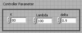
23 Trajectory Following Response K = 80; Lambda = 10; delta = 0.9;

24 Error
25 Simulation Using LabView Trajectory Generator

26 Simulation Using LabView SMC controller plant
27 Step Response
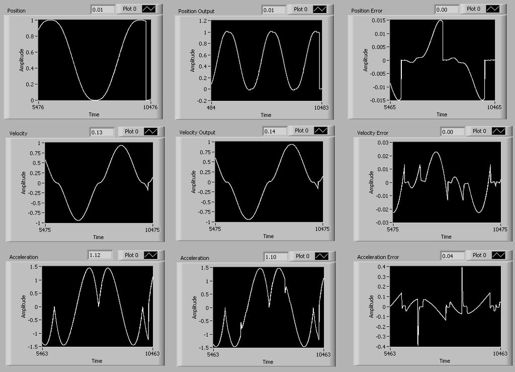
28 Trajectory Response
29 Implementation Implementation in NI Real Time can be done by replacing the runge kutta ODE solver and array composition with the real motor which is the SERVO Motor The feedback of the motor must be available (encoder)
30 Problems and Discussion Real time clock generation > Sampling time Motor parameters The feedback of the system are: Position Velocity Acceleration *) In the simulation when acceleration feedback was defined as 0, the error is still small Integral sliding mode control s t d n 1 ( λ) θ, choosing n=4 and θ θ θd is tracking error dt 0 = + =
FEEDBACK CONTROL SYSTEMS
 FEEDBAC CONTROL SYSTEMS. Control System Design. Open and Closed-Loop Control Systems 3. Why Closed-Loop Control? 4. Case Study --- Speed Control of a DC Motor 5. Steady-State Errors in Unity Feedback Control
D(s) G(s) A control system design definition
 G(s) A control system design definition") R E Compensation D(s) U Plant G(s) Y Figure 7. A control system design definition x x x 2 x 2 U 2 s s 7 2 Y Figure 7.2 A block diagram representing Eq. (7.) in control form z U 2 s z Y 4 z 2 s z 2 3 Figure
R E Compensation D(s) U Plant G(s) Y Figure 7. A control system design definition x x x 2 x 2 U 2 s s 7 2 Y Figure 7.2 A block diagram representing Eq. (7.) in control form z U 2 s z Y 4 z 2 s z 2 3 Figure
Mathematical Modeling and Dynamic Simulation of a Class of Drive Systems with Permanent Magnet Synchronous Motors
 Applied and Computational Mechanics 3 (2009) 331 338 Mathematical Modeling and Dynamic Simulation of a Class of Drive Systems with Permanent Magnet Synchronous Motors M. Mikhov a, a Faculty of Automatics,
Root Locus. Motivation Sketching Root Locus Examples. School of Mechanical Engineering Purdue University. ME375 Root Locus - 1
 Root Locus Motivation Sketching Root Locus Examples ME375 Root Locus - 1 Servo Table Example DC Motor Position Control The block diagram for position control of the servo table is given by: D 0.09 Position
Laboratory 11 Control Systems Laboratory ECE3557. State Feedback Controller for Position Control of a Flexible Joint
 Laboratory 11 State Feedback Controller for Position Control of a Flexible Joint 11.1 Objective The objective of this laboratory is to design a full state feedback controller for endpoint position control
A Model-Free Control System Based on the Sliding Mode Control Method with Applications to Multi-Input-Multi-Output Systems
 Proceedings of the 4 th International Conference of Control, Dynamic Systems, and Robotics (CDSR'17) Toronto, Canada August 21 23, 2017 Paper No. 119 DOI: 10.11159/cdsr17.119 A Model-Free Control System
School of Mechanical Engineering Purdue University. DC Motor Position Control The block diagram for position control of the servo table is given by:
 Root Locus Motivation Sketching Root Locus Examples ME375 Root Locus - 1 Servo Table Example DC Motor Position Control The block diagram for position control of the servo table is given by: θ D 0.09 See
Positioning Servo Design Example
 Positioning Servo Design Example 1 Goal. The goal in this design example is to design a control system that will be used in a pick-and-place robot to move the link of a robot between two positions. Usually
State Feedback Controller for Position Control of a Flexible Link
 Laboratory 12 Control Systems Laboratory ECE3557 Laboratory 12 State Feedback Controller for Position Control of a Flexible Link 12.1 Objective The objective of this laboratory is to design a full state
PRECISION CONTROL OF LINEAR MOTOR DRIVEN HIGH-SPEED/ACCELERATION ELECTRO-MECHANICAL SYSTEMS. Bin Yao
 PRECISION CONTROL OF LINEAR MOTOR DRIVEN HIGH-SPEED/ACCELERATION ELECTRO-MECHANICAL SYSTEMS Bin Yao Intelligent and Precision Control Laboratory School of Mechanical Engineering Purdue University West
Robust sliding mode speed controller for hybrid SVPWM based direct torque control of induction motor
 ISSN 1 746-7233, England, UK World Journal of Modelling and Simulation Vol. 3 (2007) No. 3, pp. 180-188 Robust sliding mode speed controller for hybrid SVPWM based direct torque control of induction motor
Overview of motors and motion control
 Overview of motors and motion control. Elements of a motion-control system Power upply High-level controller ow-level controller Driver Motor. Types of motors discussed here; Brushed, PM DC Motors Cheap,
Quanser NI-ELVIS Trainer (QNET) Series: QNET Experiment #02: DC Motor Position Control. DC Motor Control Trainer (DCMCT) Student Manual
 Series: QNET Experiment #02: DC Motor Position Control. DC Motor Control Trainer (DCMCT) Student Manual") Quanser NI-ELVIS Trainer (QNET) Series: QNET Experiment #02: DC Motor Position Control DC Motor Control Trainer (DCMCT) Student Manual Table of Contents 1 Laboratory Objectives1 2 References1 3 DCMCT Plant
Quanser NI-ELVIS Trainer (QNET) Series: QNET Experiment #02: DC Motor Position Control DC Motor Control Trainer (DCMCT) Student Manual Table of Contents 1 Laboratory Objectives1 2 References1 3 DCMCT Plant
Position and Velocity Profile Tracking Control for New Generation Servo Track Writing
 Preprints of the 9th World Congress The International Federation of Automatic Control Cape Town, South Africa. August 24-29, 24 Position and Velocity Profile Tracking Control for New Generation Servo Track
Integrator Windup
 3.5.2. Integrator Windup 3.5.2.1. Definition So far we have mainly been concerned with linear behaviour, as is often the case with analysis and design of control systems. There is, however, one nonlinear
Rotational Systems, Gears, and DC Servo Motors
 Rotational Systems Rotational Systems, Gears, and DC Servo Motors Rotational systems behave exactly like translational systems, except that The state (angle) is denoted with rather than x (position) Inertia
School of Mechanical Engineering Purdue University. ME375 ElectroMechanical - 1
 Electro-Mechanical Systems DC Motors Principles of Operation Modeling (Derivation of fg Governing Equations (EOM)) Block Diagram Representations Using Block Diagrams to Represent Equations in s - Domain
Chap 8. State Feedback and State Estimators
 Chap 8. State Feedback and State Estimators Outlines Introduction State feedback Regulation and tracking State estimator Feedback from estimated states State feedback-multivariable case State estimators-multivariable
Advanced Control Theory
 State Feedback Control Design chibum@seoultech.ac.kr Outline State feedback control design Benefits of CCF 2 Conceptual steps in controller design We begin by considering the regulation problem the task
Two-Link Flexible Manipulator Control Using Sliding Mode Control Based Linear Matrix Inequality
 IOP Conference Series: Materials Science and Engineering PAPER OPEN ACCESS Two-Link Flexible Manipulator Control Using Sliding Mode Control Based Linear Matrix Inequality To cite this article: Zulfatman
Robust Speed and Position Control of Permanent Magnet Synchronous Motor Using Sliding Mode Controller with Fuzzy Inference
 Preprint of the paper presented on 8 th European Conference on Power Electronics and Applications. EPE 99, 7.9-9. 1999, Lausanne, Switzerland. DOI: http://dx.doi.org/1.684/m9.figshare.74735 Robust Speed
Lecture 1: Introduction to System Modeling and Control. Introduction Basic Definitions Different Model Types System Identification
 Lecture 1: Introduction to System Modeling and Control Introduction Basic Definitions Different Model Types System Identification What is Mathematical Model? A set of mathematical equations (e.g., differential
Output high order sliding mode control of unity-power-factor in three-phase AC/DC Boost Converter
 Output high order sliding mode control of unity-power-factor in three-phase AC/DC Boost Converter JianXing Liu, Salah Laghrouche, Maxim Wack Laboratoire Systèmes Et Transports (SET) Laboratoire SeT Contents
Introduction to Feedback Control
 Introduction to Feedback Control Control System Design Why Control? Open-Loop vs Closed-Loop (Feedback) Why Use Feedback Control? Closed-Loop Control System Structure Elements of a Feedback Control System
Mechatronic System Case Study: Rotary Inverted Pendulum Dynamic System Investigation
 Mechatronic System Case Study: Rotary Inverted Pendulum Dynamic System Investigation Dr. Kevin Craig Greenheck Chair in Engineering Design & Professor of Mechanical Engineering Marquette University K.
A FORCE BALANCE TECHNIQUE FOR MEASUREMENT OF YOUNG'S MODULUS. 1 Introduction
 A FORCE BALANCE TECHNIQUE FOR MEASUREMENT OF YOUNG'S MODULUS Abhinav A. Kalamdani Dept. of Instrumentation Engineering, R. V. College of Engineering, Bangalore, India. kalamdani@ieee.org Abstract: A new
Control of Wind Turbine Generators. James Cale Guest Lecturer EE 566, Fall Semester 2014 Colorado State University
 Control of Wind Turbine Generators James Cale Guest Lecturer EE 566, Fall Semester 2014 Colorado State University Review from Day 1 Review Last time, we started with basic concepts from physics such as
Outline. Classical Control. Lecture 2
 Outline Outline Outline Review of Material from Lecture 2 New Stuff - Outline Review of Lecture System Performance Effect of Poles Review of Material from Lecture System Performance Effect of Poles 2 New
Rotary Motion Servo Plant: SRV02. Rotary Experiment #11: 1-DOF Torsion. 1-DOF Torsion Position Control using QuaRC. Student Manual
 Rotary Motion Servo Plant: SRV02 Rotary Experiment #11: 1-DOF Torsion 1-DOF Torsion Position Control using QuaRC Student Manual Table of Contents 1. INTRODUCTION...1 2. PREREQUISITES...1 3. OVERVIEW OF
Open Access Permanent Magnet Synchronous Motor Vector Control Based on Weighted Integral Gain of Sliding Mode Variable Structure
 Send Orders for Reprints to reprints@benthamscienceae The Open Automation and Control Systems Journal, 5, 7, 33-33 33 Open Access Permanent Magnet Synchronous Motor Vector Control Based on Weighted Integral
Robust Speed Controller Design for Permanent Magnet Synchronous Motor Drives Based on Sliding Mode Control
 Available online at www.sciencedirect.com ScienceDirect Energy Procedia 88 (2016 ) 867 873 CUE2015-Applied Energy Symposium and Summit 2015: ow carbon cities and urban energy systems Robust Speed Controller
Outline. Classical Control. Lecture 1
 Outline Outline Outline 1 Introduction 2 Prerequisites Block diagram for system modeling Modeling Mechanical Electrical Outline Introduction Background Basic Systems Models/Transfers functions 1 Introduction
Lab 6a: Pole Placement for the Inverted Pendulum
 Lab 6a: Pole Placement for the Inverted Pendulum Idiot. Above her head was the only stable place in the cosmos, the only refuge from the damnation of the Panta Rei, and she guessed it was the Pendulum
Control Systems Design
 ELEC4410 Control Systems Design Lecture 18: State Feedback Tracking and State Estimation Julio H. Braslavsky julio@ee.newcastle.edu.au School of Electrical Engineering and Computer Science Lecture 18:
A new FOC technique based on predictive current control for PMSM drive
 ISSN 1 746-7, England, UK World Journal of Modelling and Simulation Vol. 5 (009) No. 4, pp. 87-94 A new FOC technique based on predictive current control for PMSM drive F. Heydari, A. Sheikholeslami, K.
Power Rate Reaching Law Based Second Order Sliding Mode Control
 International OPEN ACCESS Journal Of Modern Engineering Research (IJMER) Power Rate Reaching Law Based Second Order Sliding Mode Control Nikam A.E 1. Sankeshwari S.S 2. 1 P.G. Department. (Electrical Control
An adaptive sliding mode control scheme for induction motor drives
 An adaptive sliding mode control scheme for induction motor drives Oscar Barambones, Patxi Alkorta, Aitor J. Garrido, I. Garrido and F.J. Maseda ABSTRACT An adaptive sliding-mode control system, which
Pipelined multi step A/D converters
 Department of Electrical Engineering Indian Institute of Technology, Madras Chennai, 600036, India 04 Nov 2006 Motivation for multi step A/D conversion Flash converters: Area and power consumption increase
Unity Power Factor Control of Permanent Magnet Motor Drive System
 Unity Power Factor Control of Permanent Magnet Motor Drive System M. F. Moussa* A. Helal Y. Gaber H. A. Youssef (Arab Academy for science and technology) Alexandria University *mona.moussa@yahoo.com Abstract-The
ECE317 : Feedback and Control
 ECE317 : Feedback and Control Lecture : Steady-state error Dr. Richard Tymerski Dept. of Electrical and Computer Engineering Portland State University 1 Course roadmap Modeling Analysis Design Laplace
Lab 3: Quanser Hardware and Proportional Control
 Lab 3: Quanser Hardware and Proportional Control The worst wheel of the cart makes the most noise. Benjamin Franklin 1 Objectives The goal of this lab is to: 1. familiarize you with Quanser s QuaRC tools
Design and Control of Variable Stiffness Actuation Systems
 Design and Control of Variable Stiffness Actuation Systems Gianluca Palli, Claudio Melchiorri, Giovanni Berselli and Gabriele Vassura DEIS - DIEM - Università di Bologna LAR - Laboratory of Automation
2016 Kappa Electronics Motor Control Training Series 2016 Kappa Electronics LLC. -V th. Dave Wilson Co-Owner Kappa Electronics.
 2016 Kappa Electronics Motor Control Training Series 2016 Kappa Electronics LLC V th CoOwner Kappa Electronics www.kappaiq.com Speed Sensorless FOC P Commanded Rotor Speed Commanded i d = 0 Commanded i
Stable Limit Cycle Generation for Underactuated Mechanical Systems, Application: Inertia Wheel Inverted Pendulum
 Stable Limit Cycle Generation for Underactuated Mechanical Systems, Application: Inertia Wheel Inverted Pendulum Sébastien Andary Ahmed Chemori Sébastien Krut LIRMM, Univ. Montpellier - CNRS, 6, rue Ada
Control System Design
 ELEC4410 Control System Design Lecture 19: Feedback from Estimated States and Discrete-Time Control Design Julio H. Braslavsky julio@ee.newcastle.edu.au School of Electrical Engineering and Computer Science
sc Control Systems Design Q.1, Sem.1, Ac. Yr. 2010/11
 sc46 - Control Systems Design Q Sem Ac Yr / Mock Exam originally given November 5 9 Notes: Please be reminded that only an A4 paper with formulas may be used during the exam no other material is to be
C(s) R(s) 1 C(s) C(s) C(s) = s - T. Ts + 1 = 1 s - 1. s + (1 T) Taking the inverse Laplace transform of Equation (5 2), we obtain
 R(s) 1 C(s) C(s) C(s) = s - T. Ts + 1 = 1 s - 1. s + (1 T) Taking the inverse Laplace transform of Equation (5 2), we obtain") analyses of the step response, ramp response, and impulse response of the second-order systems are presented. Section 5 4 discusses the transient-response analysis of higherorder systems. Section 5 5 gives
analyses of the step response, ramp response, and impulse response of the second-order systems are presented. Section 5 4 discusses the transient-response analysis of higherorder systems. Section 5 5 gives
Behaviour of synchronous machine during a short-circuit (a simple example of electromagnetic transients)
") ELEC0047 - Power system dynamics, control and stability (a simple example of electromagnetic transients) Thierry Van Cutsem t.vancutsem@ulg.ac.be www.montefiore.ulg.ac.be/~vct October 2018 1 / 25 Objectives
ELEC0047 - Power system dynamics, control and stability (a simple example of electromagnetic transients) Thierry Van Cutsem t.vancutsem@ulg.ac.be www.montefiore.ulg.ac.be/~vct October 2018 1 / 25 Objectives
Massachusetts Institute of Technology Department of Electrical Engineering and Computer Science Electric Machines
 Massachusetts Institute of Technology Department of Electrical Engineering and Computer Science 6.685 Electric Machines Problem Set 10 Issued November 11, 2013 Due November 20, 2013 Problem 1: Permanent
DC Shunt Excited Motor
 A DC motor has DC hunt Excited Motor A constant (DC) magnetic field for the stator, and A constant (DC) magnetic field in the rotor, That switches as the motor rotates. This switching results in a constant
AC Induction Motor Stator Resistance Estimation Algorithm
 7th WSEAS International Conference on Electric Power Systems, High Voltages, Electric Machines, Venice, Italy, November 21-23, 27 86 AC Induction Motor Stator Resistance Estimation Algorithm PETR BLAHA
EE 410/510: Electromechanical Systems Chapter 4
 EE 410/510: Electromechanical Systems Chapter 4 Chapter 4. Direct Current Electric Machines and Motion Devices Permanent Magnet DC Electric Machines Radial Topology Simulation and Experimental Studies
ENGG4420 LECTURE 7. CHAPTER 1 BY RADU MURESAN Page 1. September :29 PM
 CHAPTER 1 BY RADU MURESAN Page 1 ENGG4420 LECTURE 7 September 21 10 2:29 PM MODELS OF ELECTRIC CIRCUITS Electric circuits contain sources of electric voltage and current and other electronic elements such
International Journal of Advance Engineering and Research Development SIMULATION OF FIELD ORIENTED CONTROL OF PERMANENT MAGNET SYNCHRONOUS MOTOR
 Scientific Journal of Impact Factor(SJIF): 3.134 e-issn(o): 2348-4470 p-issn(p): 2348-6406 International Journal of Advance Engineering and Research Development Volume 2,Issue 4, April -2015 SIMULATION
Power Assist H Control of Shift Lever with Spring Connected Link
 Extended Summary pp.33 40 Power Assist H Control of Shift Lever with Spring Connected Link Mitsuo Hirata Member (Utsunomiya University) Tsutomu Ogiwara Non-member (Utsunomiya University) Hitoshi Okamoto
Introduction to Control (034040) lecture no. 2
 lecture no. 2") Introduction to Control (034040) lecture no. 2 Leonid Mirkin Faculty of Mechanical Engineering Technion IIT Setup: Abstract control problem to begin with y P(s) u where P is a plant u is a control signal
Introduction to Control (034040) lecture no. 2 Leonid Mirkin Faculty of Mechanical Engineering Technion IIT Setup: Abstract control problem to begin with y P(s) u where P is a plant u is a control signal
Sensorless Sliding Mode Control of Induction Motor Drives
 Sensorless Sliding Mode Control of Induction Motor Drives Kanungo Barada Mohanty Electrical Engineering Department, National Institute of Technology, Rourkela-7698, India E-mail: kbmohanty@nitrkl.ac.in
ET4119 Electronic Power Conversion 2011/2012 Solutions 27 January 2012
 ET4119 Electronic Power Conversion 2011/2012 Solutions 27 January 2012 1. In the single-phase rectifier shown below in Fig 1a., s = 1mH and I d = 10A. The input voltage v s has the pulse waveform shown
Inverted Pendulum System
 Introduction Inverted Pendulum System This lab experiment consists of two experimental procedures, each with sub parts. Experiment 1 is used to determine the system parameters needed to implement a controller.
GAIN SCHEDULING CONTROL WITH MULTI-LOOP PID FOR 2- DOF ARM ROBOT TRAJECTORY CONTROL
 GAIN SCHEDULING CONTROL WITH MULTI-LOOP PID FOR 2- DOF ARM ROBOT TRAJECTORY CONTROL 1 KHALED M. HELAL, 2 MOSTAFA R.A. ATIA, 3 MOHAMED I. ABU EL-SEBAH 1, 2 Mechanical Engineering Department ARAB ACADEMY
Online Model Predictive Torque Control for Permanent Magnet Synchronous Motors
 Online Model Predictive Torque Control for Permanent Magnet Synchronous Motors Gionata Cimini, Daniele Bernardini, Alberto Bemporad and Stephen Levijoki ODYS Srl General Motors Company 2015 IEEE International
Outline. Classical Control. Lecture 5
 Outline Outline Outline 1 What is 2 Outline What is Why use? Sketching a 1 What is Why use? Sketching a 2 Gain Controller Lead Compensation Lag Compensation What is Properties of a General System Why use?
EE 422G - Signals and Systems Laboratory
 EE 4G - Signals and Systems Laboratory Lab 9 PID Control Kevin D. Donohue Department of Electrical and Computer Engineering University of Kentucky Lexington, KY 40506 April, 04 Objectives: Identify the
EM Simulations using the PEEC Method - Case Studies in Power Electronics
 EM Simulations using the PEEC Method - Case Studies in Power Electronics Andreas Müsing Swiss Federal Institute of Technology (ETH) Zürich Power Electronic Systems www.pes.ee.ethz.ch 1 Outline Motivation:
6) Motors and Encoders
 Motors and Encoders") 6) Motors and Encoders Electric motors are by far the most common component to supply mechanical input to a linear motion system. Stepper motors and servo motors are the popular choices in linear motion
6) Motors and Encoders Electric motors are by far the most common component to supply mechanical input to a linear motion system. Stepper motors and servo motors are the popular choices in linear motion
Project Lab Report. Michael Hall. Hao Zhu. Neil Nevgi. Station 6. Ta: Yan Cui
 Project Lab Report Michael Hall Hao Zhu Neil Nevgi Station 6 Ta: Yan Cui Nov. 12 th 2012 Table of Contents: Executive Summary 3 Modeling Report.4-7 System Identification 7-11 Control Design..11-15 Simulation
System Modeling: Motor position, θ The physical parameters for the dc motor are:
 Dept. of EEE, KUET, Sessional on EE 3202: Expt. # 2 2k15 Batch Experiment No. 02 Name of the experiment: Modeling of Physical systems and study of their closed loop response Objective: (i) (ii) (iii) (iv)
Dynamic Modeling of Surface Mounted Permanent Synchronous Motor for Servo motor application
 797 Dynamic Modeling of Surface Mounted Permanent Synchronous Motor for Servo motor application Ritu Tak 1, Sudhir Y Kumar 2, B.S.Rajpurohit 3 1,2 Electrical Engineering, Mody University of Science & Technology,
Raktim Bhattacharya. . AERO 422: Active Controls for Aerospace Vehicles. Basic Feedback Analysis & Design
 AERO 422: Active Controls for Aerospace Vehicles Basic Feedback Analysis & Design Raktim Bhattacharya Laboratory For Uncertainty Quantification Aerospace Engineering, Texas A&M University Routh s Stability
Chapter 7. Digital Control Systems
 Chapter 7 Digital Control Systems 1 1 Introduction In this chapter, we introduce analysis and design of stability, steady-state error, and transient response for computer-controlled systems. Transfer functions,
R a) Compare open loop and closed loop control systems. b) Clearly bring out, from basics, Force-current and Force-Voltage analogies.
 Compare open loop and closed loop control systems. b) Clearly bring out, from basics, Force-current and Force-Voltage analogies.") SET - 1 II B. Tech II Semester Supplementary Examinations Dec 01 1. a) Compare open loop and closed loop control systems. b) Clearly bring out, from basics, Force-current and Force-Voltage analogies..
SET - 1 II B. Tech II Semester Supplementary Examinations Dec 01 1. a) Compare open loop and closed loop control systems. b) Clearly bring out, from basics, Force-current and Force-Voltage analogies..
The output voltage is given by,
 71 The output voltage is given by, = (3.1) The inductor and capacitor values of the Boost converter are derived by having the same assumption as that of the Buck converter. Now the critical value of the
Unity Power Factor Control of Permanent Magnet Motor Drive System
 Unity Power Factor Control of Permanent Magnet Motor Drive System M. F. Moussa* A. Helal Y. Gaber H. A. Youssef (Arab Academy for science and technology) Alexandria University *mona.moussa@yahoo.com Abstract-The
Improved efficiency of a fan drive system without using an encoder or current sensors
 Improved efficiency of a fan drive system without using an encoder or current sensors Tian-Hua Liu, Jyun-Jie Huang Department of Electrical Engineering, National Taiwan University of Science Technology,
Automatic Generation Control. Meth Bandara and Hassan Oukacha
 Automatic Generation Control Meth Bandara and Hassan Oukacha EE194 Advanced Controls Theory February 25, 2013 Outline Introduction System Modeling Single Generator AGC Going Forward Conclusion Introduction
A sliding mode control for a wound rotor synchronous generator with an isolated RL load
 21 American Control Conference Marriott Waterfront, Baltimore, MD, USA June 3-July 2, 21 ThA5.6 A sliding mode control for a wound rotor synchronous generator with an isolated RL load R.S. Muñoz-Aguilar,
Lab 5a: Pole Placement for the Inverted Pendulum
 Lab 5a: Pole Placement for the Inverted Pendulum November 1, 2011 1 Purpose The objective of this lab is to achieve simultaneous control of both the angular position of the pendulum and horizontal position
School of Mechanical Engineering Purdue University. ME375 Feedback Control - 1
 Introduction to Feedback Control Control System Design Why Control? Open-Loop vs Closed-Loop (Feedback) Why Use Feedback Control? Closed-Loop Control System Structure Elements of a Feedback Control System
SYNCHRONIZATION CRITERION OF CHAOTIC PERMANENT MAGNET SYNCHRONOUS MOTOR VIA OUTPUT FEEDBACK AND ITS SIMULATION
 SYNCHRONIZAION CRIERION OF CHAOIC PERMANEN MAGNE SYNCHRONOUS MOOR VIA OUPU FEEDBACK AND IS SIMULAION KALIN SU *, CHUNLAI LI College of Physics and Electronics, Hunan Institute of Science and echnology,
1 x(k +1)=(Φ LH) x(k) = T 1 x 2 (k) x1 (0) 1 T x 2(0) T x 1 (0) x 2 (0) x(1) = x(2) = x(3) =
=(Φ LH) x(k) = T 1 x 2 (k) x1 (0) 1 T x 2(0) T x 1 (0) x 2 (0) x(1) = x(2) = x(3) =") 567 This is often referred to as Þnite settling time or deadbeat design because the dynamics will settle in a Þnite number of sample periods. This estimator always drives the error to zero in time 2T or
567 This is often referred to as Þnite settling time or deadbeat design because the dynamics will settle in a Þnite number of sample periods. This estimator always drives the error to zero in time 2T or
An Introduction to Control Systems
 An Introduction to Control Systems Signals and Systems: 3C1 Control Systems Handout 1 Dr. David Corrigan Electronic and Electrical Engineering corrigad@tcd.ie November 21, 2012 Recall the concept of a
Modeling and Simulation of the Nonlinear Computed Torque Control in Simulink/MATLAB for an Industrial Robot
 Copyright 2013 Tech Science Press SL, vol.10, no.2, pp.95-106, 2013 Modeling and Simulation of the Nonlinear Computed Torque Control in Simulink/MATLAB for an Industrial Robot Dǎnuţ Receanu 1 Abstract:
Lecture 4: Losses and Heat Transfer
 1 / 26 Lecture 4: Losses and Heat Transfer ELEC-E845 Electric Drives (5 ECTS) Marko Hinkkanen Aalto University School of Electrical Engineering Autumn 215 2 / 26 Learning Outcomes After this lecture and
6.003: Signals and Systems
 6.003: Signals and Systems CT Feedback and Control October 20, 2011 1 Mid-term Examination #2 Wednesday, October 26, 7:30-9:30pm, No recitations on the day of the exam. Coverage: Lectures 1 12 Recitations
Modeling and Robust Output feedback Tracking Control of a Single-phase Rotary Motor with Cylindrical Halbach Array
 214 IEEE/ASME International Conference on Advanced Intelligent Mechatronics (AIM) July 8-11, 214. Besançon, France Modeling and Robust Output feedback Tracking Control of a Single-phase Rotary Motor with
Belt Tension Clamp. Drive Motor. Friction Brake. Load. Encoder 2. Drive. (4000 lines/rev incremental) Encoder 1. (4000 lines/rev incremental)
 Encoder 1. (4000 lines/rev incremental)") Industrial Servo System Introduction The first part this lab is to investigate how the dynamic response of a closed-loop system can be used to determine the mass moment of inertia of a model industrial
Industrial Servo System Introduction The first part this lab is to investigate how the dynamic response of a closed-loop system can be used to determine the mass moment of inertia of a model industrial
Optimization of Model-Reference Variable-Structure Controller Parameters for Direct-Current Motor
 Journal of Computations & Modelling, vol., no.3, 1, 67-88 ISSN: 179-765 (print), 179-885 (online) Scienpress Ltd, 1 Optimization of Model-Reference Variable-Structure Controller Parameters for Direct-Current
A Novel Adaptive Estimation of Stator and Rotor Resistance for Induction Motor Drives
 A Novel Adaptive Estimation of Stator and Rotor Resistance for Induction Motor Drives Nagaraja Yadav Ponagani Asst.Professsor, Department of Electrical & Electronics Engineering Dhurva Institute of Engineering
3 Lab 3: DC Motor Transfer Function Estimation by Explicit Measurement
 3 Lab 3: DC Motor Transfer Function Estimation by Explicit Measurement 3.1 Introduction There are two common methods for determining a plant s transfer function. They are: 1. Measure all the physical parameters
2.004 Dynamics and Control II Spring 2008
 MIT OpenCourseWare http://ocw.mit.edu 2.004 Dynamics and Control II Spring 2008 For information about citing these materials or our Terms of Use, visit: http://ocw.mit.edu/terms. Massachusetts Institute
Mechatronics Engineering. Li Wen
 Mechatronics Engineering Li Wen Bio-inspired robot-dc motor drive Unstable system Mirko Kovac,EPFL Modeling and simulation of the control system Problems 1. Why we establish mathematical model of the control
Robust Loop Shaping Force Feedback Controller
 Robust Loop Shaping Force Feedback Controller Dynamic For Effective Force Force Control Testing Using Loop Shaping Paper Title N. Nakata & E. Krug Johns Hopkins University, USA SUMMARY: Effective force
Steady State Errors. Recall the closed-loop transfer function of the system, is
 Steady State Errors Outline What is steady-state error? Steady-state error in unity feedback systems Type Number Steady-state error in non-unity feedback systems Steady-state error due to disturbance inputs
On Practical Applications of Active Disturbance Rejection Control
 2010 Chinese Control Conference On Practical Applications of Active Disturbance Rejection Control Qing Zheng Gannon University Zhiqiang Gao Cleveland State University Outline Ø Introduction Ø Active Disturbance
ECE 422/522 Power System Operations & Planning/Power Systems Analysis II : 7 - Transient Stability
 ECE 4/5 Power System Operations & Planning/Power Systems Analysis II : 7 - Transient Stability Spring 014 Instructor: Kai Sun 1 Transient Stability The ability of the power system to maintain synchronism
CDS 101: Lecture 2.1 System Modeling
 CDS 101: Lecture 2.1 System Modeling Richard M. Murray 4 October 2004 Goals: Define what a model is and its use in answering questions about a system Introduce the concepts of state, dynamics, inputs and
Laboratory Exercise 1 DC servo
 Laboratory Exercise DC servo Per-Olof Källén ø 0,8 POWER SAT. OVL.RESET POS.RESET Moment Reference ø 0,5 ø 0,5 ø 0,5 ø 0,65 ø 0,65 Int ø 0,8 ø 0,8 Σ k Js + d ø 0,8 s ø 0 8 Off Off ø 0,8 Ext. Int. + x0,
Lecture 9 Nonlinear Control Design. Course Outline. Exact linearization: example [one-link robot] Exact Feedback Linearization
![Lecture 9 Nonlinear Control Design. Course Outline. Exact linearization: example [one-link robot] Exact Feedback Linearization](/thumbs/83/87856505.jpg "Lecture 9 Nonlinear Control Design. Course Outline. Exact linearization: example [one-link robot] Exact Feedback Linearization") Lecture 9 Nonlinear Control Design Course Outline Eact-linearization Lyapunov-based design Lab Adaptive control Sliding modes control Literature: [Khalil, ch.s 13, 14.1,14.] and [Glad-Ljung,ch.17] Lecture
Lecture 9 Nonlinear Control Design Course Outline Eact-linearization Lyapunov-based design Lab Adaptive control Sliding modes control Literature: [Khalil, ch.s 13, 14.1,14.] and [Glad-Ljung,ch.17] Lecture
Lecture (20) DC Machine Examples Start of Synchronous Machines
 DC Machine Examples Start of Synchronous Machines") Lecture (20) DC Machine Examples Start of Synchronous Machines Energy Systems Research Laboratory, FIU All rights reserved. 20-1 Energy Systems Research Laboratory, FIU All rights reserved. 20-2 Ra R f
Lecture (20) DC Machine Examples Start of Synchronous Machines Energy Systems Research Laboratory, FIU All rights reserved. 20-1 Energy Systems Research Laboratory, FIU All rights reserved. 20-2 Ra R f
Backstepping Control with Integral Action of PMSM Integrated According to the MRAS Observer
 IOSR Journal of Electrical and Electronics Engineering (IOSR-JEEE) e-issn: 2278-1676,p-ISSN: 232-3331, Volume 9, Issue 4 Ver. I (Jul Aug. 214), PP 59-68 Backstepping Control with Integral Action of PMSM