VIBRATION AND ACOUSTIC PERFORMANCE OF IN-PLANE HONEYCOMB SANDWICH PANELS
|
|
|
- Frederica Mosley
- 6 years ago
- Views:
Transcription

1 Clemson University TigerPrints All Theses Theses 8-01 VIBRATION AND ACOUSTIC PERFORMANCE OF IN-PLANE HONEYCOMB SANDWICH PANELS Xiao Gong Clemson University, Follow this and additional works at: Part of the Mechanical Engineering Commons Recommended Citation Gong, Xiao, "VIBRATION AND ACOUSTIC PERFORMANCE OF IN-PLANE HONEYCOMB SANDWICH PANELS" (01). All Theses. Paper This Thesis is brought to you for free and open access by the Theses at TigerPrints. It has been accepted for inclusion in All Theses by an authorized administrator of TigerPrints. For more information, please contact
2 VIBRATION AND ACOUSTIC PERFORMANCE OF IN-PLANE HONEYCOMB SANDWICH PANELS A Thesis Presented to the Graduate School of Clemson University In Partial Fulfillment of the requirements for the degree Master of Science Mechanical Engineering By Xiao Gong August 01 Accepted by: Dr.Lonny L.Thompson, Committee Chair Dr.Gang Li Dr. Mohammed Daqaq
3 ABSTRACT Sandwich panel structures constructed with cellular honeycomb cores allow for control of acoustic performance due to their ability to optimize effective orthotropic material properties with changes in cell geometry. By modification of topology and geometric parameters of a unit cell, desirable effective properties can be obtained and used to design lightweight structures with reduced vibration and increased sound transmission loss properties. Thus investigating the relation between the geometric configuration of the honeycomb core and vibration and acoustic behavior is important to optimize design of sandwich panels. In this work, a finite element model is developed in MATLAB to evaluate the resonance frequencies, vibration frequency response and structural behavior of general honeycomb sandwich panels undergoing in-plane loading. Bernoulli-Euler beam element stiffness and mass matrices are computed with coordinate transformations to assemble for two-dimensional frame dynamic analysis. The developed MATLAB finite element program is written to allow the user to specify any unit cell geometry together with the number of repeated cells along the longitudinal and transverse direction of a honeycomb sandwich panel. This automation allows for rapid studies of the effects of the cell geometry and number of cells for optimization and parametric studies. In addition, the user can specify the size of elements for cell length subdivision to ensure mesh convergence analysis. The developed MATLAB code was verified by comparing dynamic results to finite element models created using the commercial software ABAQUS using both cubic i
4 Bernoulli-Euler and quadratic Timoshenko beam elements. Natural vibration frequencies of the structure and vibration amplitude frequency response for honeycomb structures are computed between 1~1000 Hz, corresponding to low to medium frequency ranges. In addition, the ABAQUS finite element model is used to simulate the acoustic behavior of the sandwich panel mounted in a rigid baffle resulting from an incident plane pressure wave. This required the coupling of an acoustic finite element model tied to the sandwich panel model to model sound radiation from the vibrating panel. To model the infinite acoustic region on one side of the sandwich panel, the acoustic finite element mesh is truncated using a founded ellipse non-reflecting boundary condition (NRBC). Previous studies used a circular nonreflecting boundary condition. The use of an ellipse for the NRBC allows for a reduced size computational region surrounding the elongated sandwich panel structure. The accuracy of the NRBC s was also studied as a function of distance from the vibrating panel source. Various core configurations of different geometric and effective material properties for regular and auxetic honeycomb cell geometries with two different orthogonal orientations were studied. Constant mass property is applied for sandwich panels with different number of longitudinal and transverse cell numbers to identify the effects of core geometry, cell truncation at face sheets, and effective properties on structural and acoustic behavior. Flexural and local dilatational vibration modes for the various configurations were identified. The influence of natural frequencies on the acoustic performance of the sandwich panels is also studied. ii
5 DEDICATION I would like to dedicate this thesis to my parents Hongjie Gong, Hong Huang and my sister Shan Huang and other family members. In addition, I also like to thank my girl friend Szuyu Chen for her continued support. iii
6 ACKNOWLEDGEMENTS First, I would like to thank Dr. Lonny L Thompson. My thesis can not be finished without his help and instruction. He helped me with my researches during the whole graduate study. In addition, he recommended me as grader for three semesters which gived me finantial supprot.i would also like to thank my committee member, Dr.Gang Li and Dr. Mohammed Daqaq. They reviewd my thesis and gave suggestions. Finaly, I would like to give thanks for my friends in mechanical engineering department for their support. iv
7 TABLE OF CONTENTS ABSTRACT... i DEDICATION... iii ACKNOWLEDGEMENTS... iv TABLE OF CONTENTS... v LIST OF TABLES... vii LIST OF FIGURES... viii CHAPTER 1: INTRODUCTION Honeycomb Sandwich Panels Sound Transmission Characteristics Previous Work of Acoustic Behavior In Honeycomb Sandwich Panels Thesis Objectives Thesis Outline... 7 CHAPTER : BERNOULLI-EULER BEAM ELEMENT THEORY Degrees of Freedom And Shape Function Beam Strain Energy and Elastic Stiffness Matrices Beam Kinetic Energy and Mass Matrices Load Vector Coordinate Transformation for Frames CHAPTER 3: EFFECTIVE MATERIAL PROPERTIES AND GEOMETRY OF HONEYCOMB SANDWICH PLATES Geometric and Material Parameters of Honeycomb Sandwich Panels Modeling Effective Properties Effective Properties of Honeycomb Cell Effective Properties of Sandwich Panel Controlling Unit Cell Geometry... 1 CHAPTER 4: IMPLEMENTING OF FINITE ELEMENT MODEL IN MATLAB Generating Honeycomb Sandwich Panel Geometry Structure Preprocessing Process... 6 CHAPTER 5: IMPLEMENTING OF ACOUSTIC FINITE ELEMENT MODEL IN ABAQUS... 9 v
8 5.1 Geometric and Material properties Mesh Constraints Boundary Condition and Load Natural Frequency Extraction Procedure Steady State Dynamic, Direct Procedure CHAPTER 6: NATURAL FREQUENCIES ANALYSIS FOR SANDWICH PANELS WITH VARYING CORE GEOMETRY Geometry Parameters and Effective Properties Comparison of ABAQUS and MATLAB Results Natural Frequencies Result Relations of Effective Properties and Natural Frequencies Mode Shape CHAPTER 7: STRUCTURAL-ACOUSTIC PERFORMANCE OF SANDWICH PANELS Structural Response Sound Transmission Loss Model Accuracy Sound Transmission Results with Various Configurations Comparsion and Discussion Acoustic Pressure Distributions CHAPTER 8: CONCLUSION AND FUTURE WORK Conclusive Remarks Future Work Reference vi
9 LIST OF TABLES Table 1.1: Definition of analysis scale levels... Table 4.1: Input parameters for Geometric and Material properties... 5 Table 4.: Nodes and elements matrices... 5 Table 4.3: Gauss points and weight... 7 Table 6.1: Geometries and effective properties of Orientation I 40x1 cells Table 6.: Geometries and effective properties of Orientation I 80x cells Table 6.3: Geometries and effective properties of Orientation II 40x3 cells Table 6.4: Comparison of first ten natural frequencies for Orientation I 40x1 honeycomb core... 4 Table 6.5: Comparison of first ten natural frequencies for Orientation I 40x1 honeycomb core... 4 Table 6.6: Comparison of first ten natural frequencies for Orientation I 40x1 honeycomb core Table 6.7: Comparison of first ten natural frequencies for Orientation I 40x1 honeycomb core Table 6.8: Natural frequencies of orientation I 40x Table 6.9: Natural Frequencies of Orientation I 80x Table 6.10: Natural Frequencies of Orientation II 40x Table 6.11: First natural frequencies of dilatational mode shape with vary cells Table 7.1: First natural frequency and spacing between peaks on rms curve of various core configurations Table 7.: Areas under sound transmission curve vii
10 LIST OF FIGURES Figure 1.1 Analysis levels of sandwich panels... 1 Figure 1.: Honeycomb core of sandwich panel... Figure 1.3 Principal dependence of sound transmission loss of a panel... 3 Figure.1: Degree of freedom Figure 3.1: Sandwich panels of orientation I (longitudinal) Figure 3.: Sandwich panels of orientation II (transverse) Figure 3.3: Unit cell formation of Orientation I Figure 3.4: Unit cell formation of Orientation II Figure 3.5: Baffled sandwich panel with distribute load Figure 3.6: Sandwich panel with thickness shown... 0 Figure 4.1: Single (a) regular and (b) auxetic honeycomb... 3 Figure 4.3: Regular honeycomb of Orientation II... 4 Figure 4.: Regular double row honeycomb (a) before and (b) after mesh... 4 Figure 5.1: Analysis model in ABAQUS Figure 5.: Mesh of air domain Figure 5.3: Constraints between air domain and sandwich plate... 3 Figure 5.4: Boundary conditions and load Figure 5.5: Steady-state dynamic, direct step Figure 6.1: Straight member length h Vs varying cell angles Figure 6.: Angle member length l Vs varying cell angles Figure 6.3: Cell thickness t Vs varying cell angles Figure 6.4: Effective shear modulus Vs varying cell angles Figure 6.5: Effective Young s modulus of transverse direction Vs varying cell angles Figure 6.6: Effective Young s modulus of longitudinal direction Vs varying cell angles Figure 6.7: First natural frequency Vs varying cell angles Figure 6.8: First natural frequency Vs Effective Shear Modulus viii
11 Figure 6.9: First natural frequency Vs Effective Young s Modulus in longitudinal direction Figure 6.1 : First natural frequency Vs Effective Young s Modulus of transverse direction Figure 6.11: First ten mode shape of panel of orientation I 40x1 cells Figure 6.1: Selected dilatational mode shapes of - Orientation I 40x1 cells Figure 7.1: rms of orientation I 40x1 structure with angle Figure 7.: rms for orientation I 40x1 structure with positive angle Figure 7.3: rms for Orientation I 40x1 structure with negative angle Figure 7.4: rms for Orientation I 40x1 with different angle Figure 7.5: rmsfor different orientation with angle Figure 7.6: STL results of fine and coarse mesh Figure 7.7: STL results of Semi-circle and Ellipse domain with same longitudinal length Figure 7.8: STL for Orientation I 40x1 structure with angle Figure 7.9 STL for Orientation I 40x1 structure with positive angle Figure 7.10: STL for Orientation I 40x1 structure with negative angle Figure 7.11: STL for Orientation I 40x1 structure with different angle Figure 7.1: STL for different orientation with angle... 6 Figure 7.13: STL for different orientation with angle... 6 Figure 7.14: rms results with reverse axis Figure 7.15: rms for orientation I 40x1 cells with angle with different in-plane thicknesses Figure 7.16: STL of the Orientation I 40x1 cell with different in-plane thicknesses Figure 7.17: Sound pressure level of panel with Orientation I 40x1 cells Figure 7.18: Sound pressure level of - panel with Orientation I 40x1 cells Figure 7.19: Radiated sound pressure level of panel with Orientation I 40x1 at selected frequency with dilatational mode shapes... 7 ix
12 Figure 8.1: Auxetic honeycomb topologies: (a) chiral[31]; (b) x
13 CHAPTER 1: INTRODUCTION 1.1 Honeycomb Sandwich Panels Honeycomb sandwich panels has been widely used in aerospace industry, motor vehicle technology and light-weight construction for decades. Sandwich panels with honeycomb cores offer both stiffness and light-weight compare to other panels [1]. Besides the traditional hexagonal honeycomb structure, auxetic, square, rectangular, chiral honeycomb and other cellular structure are also applied as the core of the sandwich panels []. In addition, various materials as aluminum, titanium and polymers can be used to manufacture the honeycomb sandwich panels to satisfy the desire properties as stiffness, thermal conductivity etc. The design of sandwich panels can be divided into four analysis levels as shown in Figure 1.1 Micro Meso Meta Macro Figure Figure 1.1: 1.1 Analysis Analysis levels levels of of sandwich sandwich panels panels The control of effective properties of the core and whole sandwich panel can be 1


14 obtained through the modification of the cellular geometry of the honeycomb core in Meso level and material chosen in the Micro level. Table 1.1 gives the definition and example of the analysis level for sandwich panels studied in this work [3], [3]. Table 1.1: Definition of analysis scale levels Level Definition Example Effective properties of sandwich Effective in-plane bend and Macro panels determined by core and shear stiffness face sheets Meta Meso Micro Effective properties of honeycomb core controlled by lesser order parameter Intermediate level parameters that define to control honeycomb unit cell geometry Constitutive properties assigned to the honeycomb Effective bend and shear moduli, effective density, effective Poisson s ration Cell wall height, length,wall thickness, internal angle Density, moduli, Poisson s ration of host material Most honeycomb sandwich panels used for applications are out-of-plane ones, since honeycombs are stiffer in the out-of-plane direction. However in this work, the in-plane sandwich panels are mainly studied to evaluate the structural response and acoustic performance for more flexible honeycomb structures. (b) Out-of-plane (a) In-plane Figure 1.: Honeycomb core of sandwich panel
15 Stiffness controlled Resonance controlled Mass controlled Coincidence controlled 1. Sound Transmission Characteristics Sound insulation is a property reducing the sound pressure level with respect to a specified sound source and receptor. Through the sound insulation, airborne sound can be kept out of a protected space [5]. Sound transmission loss (also known as sound reduction index) is used to describe the performance of sound insulation. Sound insulation depends on the frequency range and the material and geometry of the structure. The dependence of sound transmission through a panel as a function of frequency for a typical geometry and material is shown in Figure 1.3 [7]. Sound transmission loss (db) Frequency (Hz) Critical frequency Extension of Mass law Figure 1.3: Principal dependence of sound transmission loss of a panel The sound transmission loss characteristics for the different frequency ranges can 3
16 be explained by examining the analytical expression derived for a vibrating elastic finite panel mounted in an infinite rigid baffle and radiating sound in air. The sound transmission loss for the sandwich panels of zero incident angle pressure waves can be expressed as [6] f fmn f fmn STL c f c f (1.1) where is mass per unit area, f is the frequency of sound, f mn is the resonance frequency and c is the velocity of sound, refers to the damping loss factor. As illustrate in the Figure, very low frequencies the sound insulation is controlled by the stiffness of the panel. STL can be approximate as f f1 STL( stiffness) 10log 1 f (1.) It can be seen in the equation 1., by changing the first natural frequency which is determined by the stiffness of the panel. The stiffness controlled frequency range can be modified to desired value. At higher frequencies in a mid-frequency range, the sound transmission is influenced by the natural resonances of the panel. The host material of panel in micro level, geometry of cellular core in meso level and boundary condition will contribute to the value of natural frequencies. For the mass controlled range, the sound transmission loss can be approxiated as [6]: STL( mass) 0log 0log f 4 (1.3) 4
17 In this range, the sound transmission loss at certain frequency is mainly determined by the mass of the panel. Thus it is not appropriate to use honeycomb sandwich panel for sound insulation in this frequency range, since it has a very low effective density. At an even higher frequency coincidence between bending waves and incident waves can be observed [5]. The sound transmission loss at this range is lower than the expected value determined by the mass law. 1.3 Previous Work of Acoustic Behavior In Honeycomb Sandwich Panels Structural and acoustic properties of sandwich panels have been studied for decades. Many researchers have established analytical model for the sound transmission analysis of sandwich panels. Kurtz and Watters [7] were the pioneers to study the sound transmission loss in laminated plates and pointed out that sandwich panels may possess a better stiffness property than the single layer panel. However, the sandwich panels they used for analysis were assumed incompressible which is not capable of simulate the dilatational vibration. Ford [8] developed a three layer model of sandwich panels with a compressible core. An expression for kinetic energy was proposed to indicate the effects of sound transmission. The author also compared the wave numbers to predict the coincidence frequencies for both symmetric and anti-symmetric motions of the sandwich panels. Based on ford s studies, Smolenski and Krokosky [9]modified the energy expression and discussed the influence of core effective properties on the resonance frequencies of dilatational vibration. They also used the natural frequencies to explain the dips on 5
18 sound transmission cures. Besides the isotropic cores, sound transmission loss in the sandwich panels with orthotropic cores was studied by Moore and Lyon[10]. The effects of stiffness, thickness and material properties on sound transmission performance of asymmetric sandwich panels was also investigated by Dym and Lang [11], [1], [13]. The acoustic performance of sandwich panel with cellular core has been studied recently. Sound transmission of truss-like periodic sandwich panels were first investigated by Michael EI-Raheb and Paul Wagner [14], [15]. In their work, the vibration of the sandwich panels is measured and to predict the sound transmission loss. Acoustic optimizations of sandwich panels were also studied by several researchers [16]. Through the topological design of periodic multifunctional core and honeycomb core, minimum sound radiation could be achieved []. Ruzzene [5] introduced a finite element method to measure the sound transmission loss and structural performance of the sandwich panels with square truss and honeycomb cores. Spectral elements were used to ensure the accuracy of the results at high frequency range. 1.4 Thesis Objectives In this thesis, the objective is to study the effects of honeycomb cell geometry and number of cells, and orientation of cells on the vibration amplitude and sound transmission loss. The frequency range studied is in the stiffness and resonance regions, and not in the mass controlled high-frequency region. As a result, traditional Bernoulli- Euler beam finite elements are sufficient to simulate the 6
19 dynamic vibratory behavior of sandwich panels. A MATLAB program is written to compute the mass and stiffness matrices, assemble for two-dimensional dynamic frame analysis, and automate the generation of repetitive honeycomb cells in both longitudinal and transverse directions. In addition, the user of the MATLAB program can define the element size to ensure an accurate finite element mesh for honeycomb sandwich structures with any cell geometry. ABAQUS commercial finite element software is used to verify the MATLAB program for natural frequencies and vibration amplitude frequency response of the sandwich panel and also to model and correlate sound transmission loss for a coupled structural acoustic analysis. 1.5 Thesis Outline The overview of the thesis is summarized and illustrated as flow chart in Figure1.4 7
20 Chapter 1 Introduction Chapter Theory of Bernoulli-Euler beam element Chapter 3 Effective material properties and geometry Chapter 4 Finite element model in MATLAB Chapter 5 Finite element model in ABAQUS Chapter 6 Natural frequencies analysis Chapter 7 Structural-Acoustic Performance Chapter 8 Conclusions Figure 1.4: Overview of thesis 8
21 Chapter 1 gives a brief view of the characteristics and advantages of honeycomb sandwich panels in applications. Previous researches about sound insulation in sandwich panels are reviewed and summarized. The relations between honeycomb core effective properties and acoustic performance are demonstrated. Chapter introduces the Bernoulli-Euler beam theory used for finite elements modeling. Stiffness and mass matrices are derived by the kinetic and strain energy expressing as well as the load vector. Chapter 3 discusses the effective properties for honeycomb cell and whole sandwich panel. The method of controlling the structure size of unit cell through the change of geometric parameters is also discussed. Chapter 4 and 5 discuss the specific steps of implementing finite element models of sandwich panels in ABAQUS and MATLAB. The concepts of generating the geometry of honeycomb core in MATLAB is introduced, thus it is capable of simulating the sandwich panels with various geometric parameters. Chapter 6 discusses and compares the natural frequency results of the sandwich panels with two different orientations and various core geometries. Models with internal angle from 45 to 45 in different orientation are studied with constant mass. Another study for the models of same structure with different thickness is also made. Chapter 7 presents and discusses the results of vibration and acoustic performance of different models introduced in chapter 6. Sound radiation results are also compare to the sound transmission and structural response results. 9
22 Chapter 8 summarizes the study and conclusions of the results are made. Suggestions for future work about the research using the developed Matlab program and finite models are also discussed. 10
23 CHAPTER : BERNOULLI-EULER BEAM ELEMENT THEORY Bernoulli-Euler beam Element is D homogeneous beam element, neglecting shear deformation and rotator moment of inertia [8]..1 Degrees of Freedom And Shape Function v v u u v1 v 1 u 1 y 1 u 1 x Figure.1: Degree of freedom Each node in the Bernoulli-beam element has three nodal degrees of freedom, while each element contains two nodes. ( e) is the vector of degree of freedom (DOF) of single element. ( e) { } u v u v (.1) T The approximation for extension of neutral axis is given by x1 and x u( x, t) ( x) u ( x) u (.) x1 1 x4 are the shape function and can be derived as x 1( x) x 1( x) 1 (.3) L 11
24 x ( x) x4( x) (.4) L The approximation for bending of the neutral axis, w( x, t) ( x) v ( x) ( x) v ( x) (.5) y 1 y3 1 y5 y6 Shape function can be derived as 3 x x N1( x) y( x) 13 L L 3 x x x N( x) y3( x) L L L L 3 x x N3( x) y5( x) 3 L L 3 x x N4( x) y6( x) L L L (.6) (.7) (.8) (.9). Beam Strain Energy and Elastic Stiffness Matrices The elastic potential energy of beam is the strain energy which can be evaluated separately for extension and bending effects. For extension the strain energy is related to the uniform extensional strain. 1 L V EA( ) 0 xx dx 1 L ' ( ) 0 j j j1 EA x u dx (.10) For bending, the strain energy is related to the curvature w k ( N ( x) v N ( x) ) (.11) z j j j j x j1 The strain energy can be expressed as 1
25 1 L V EI( k ) 0 z dx 1 0 L EI ( N j ( x) v j N j( x) j ) dx j1 (.1) For homogeneous isotropic beams, substituting the shape functions into equation.1 and take the second derivative, then element stiffness matrices K can be approximated as EA EA L L 1EI 6EI 1EI 6EI L L L L 4EI 6EI 4EI 0 K L L L EA 0 0 L 1EI 6EI SYM 0 3 L L 4EI L (.13).3 Beam Kinetic Energy and Mass Matrices The kinetic energy and mass of beam can be determined separately for extensional velocities and transverse velocities. For extensional velocities, the kinetic energy is T 1 0 L A( u) dx 1 L ' ( ) 0 j j j1 A x u dx (.14) For transverse velocities 1 L T A( w) dx L ' ' A( N j ( x) v j N j ( x) j ) dx j1 (.15) 13
26 Substituting the shape functions into equation.15 and take the second derivative, then element stiffness matrices M can be approximated as L L AL 4L 0 13L 3L M SYM 156 L 4L.4 Load Vector (.16) The work of the external force is the combination of the distributed longitudinal and transverse load. For longitudinal load W For transverse load L 0 L u() x q dx 0 j 1 u () x u q dx j j u (.17) W 0 L w( x) q dx L 4 0 j 1 w ( N ( x) v N ( x) ) q dx j j j j w (.18) And the load coefficient can be expressed as F w( x) f ( ) dx i 0 L 0 L w 4 f ( ) ( x) dx n 1 yi (.19) So the load vector is f L f L f L f L w w w w F 0 0 (.0) Coordinate Transformation for Frames T Geometric relation between (degree of freedom in local coordinate) and 14
27 (degree of freedom in global coordinate) is [ R]. Where R u u cos v sin (.1) v u sin v cos (.) (.3) c s 0 s c c s 0 0 s c c s x x L 1 cos (.5) y y L 1 sin (.6) (.4) T The stiffness matrices in global coordinates is K R K R K EA EA EA EA c cs c cs L L 6EI L L 6EI s s 1EI 1EI L 1EI 1EI L s cs s cs L L L L EA EA EA cs cs s L 6EI L L 6EI c c 1EI L 1EI 1EI L cs cs c L L L 4EI 6EI 6EI EI s c L L L L EA EA c cs L L 6EI s 1EI 1EI L s cs 3 3 L L EA s L 6EI SYM c 1EI L c 3 L 4EI L (.7) 15
28 T The stiffness matrices in global coordinates ism R M R M 140c 16cs sl 70c 16cs 13sL 15s 54s 140s cl 16cs 70s 13cL 156c 54c 4L 13sL 13cL 3L 140c 16cs sl 156s SYM 140s cl 156c 4L (.8) 16
29 CHAPTER 3: EFFECTIVE MATERIAL PROPERTIES AND GEOMETRY OF HONEYCOMB SANDWICH PLATES 3.1 Geometric and Material Parameters of Honeycomb Sandwich Panels Modeling The sandwich plate studied in this work consisted with three parts, two face sheets and honeycomb core. Two different kind of orientation in Figure 3.1 are used for analysis. In orientation I the honeycomb unit cell is set in longitudinal direction while it is set in transverse direction for another orientation. (a) Regular honeycomb cell Orientation I (b) Auxetic honeycomb cell Figure 3.1: Sandwich panels of orientation I (longitudinal) (c) Regular honeycomb cell Orientation II (d) Auxetic honeycomb cell Figure 3.: Sandwich panels of orientation II (transverse) 17
30 Ly Ly Lx Lx Figure 3.3: Unit cell formation of Orientation I Ly Ly Lx Lx Figure 3.4: Unit cell formation of Orientation II The overall Length of the plate is L=m and with the depth H=86.6mm. Both the face sheets and the honeycomb core units are made of aluminum. The young s 3 modulus for the material E=7.1e10, mass density is 700 kg m. The top and bottom face sheet are both.5 mm thick, while the thickness of each honeycomb element is varied for every different sandwich panels. The out of plane thickness of the panel b is kept the same for every sandwich panels and given the value of unity 18
![for simplicity. In the analysis model considering here, the sandwich plate is connected to the rigid baffle of infinite length at two ends by pin joints [16].](/docs-images/76/73174936/images/31-0.jpg "A plane incident pressure wave is excited at the bottom face sheet. And an elliptical bounded air fluid domain is tied to the top layer of the sandwich panel.")
31 for simplicity. In the analysis model considering here, the sandwich plate is connected to the rigid baffle of infinite length at two ends by pin joints [16]. A plane incident pressure wave is excited at the bottom face sheet. And an elliptical bounded air fluid domain is tied to the top layer of the sandwich panel. Through the honeycomb core and top face sheet, the incident pressure wave is transmitted, and radiates the sound to the air fluid domain. Absorbing Impedance Air fluid domain Rigid baffle Sandwich panel Incident pressure wave y x Figure 3.5: Baffled sandwich panel with distribute load 19

32 3. Effective Properties 3..1 Effective Properties of Honeycomb Cell By changing the geometric parameters of the honeycomb cellular, its linear-elastic behavior will vary and different from the original material. Gibson and Ashby s cellular material theory [7] introduced formulas for effective properties for honeycomb structure using Bernoulli-Euler beam theory. Mass density, Young s modulus for longitudinal and transverse direction, shear modulus are the effective properties studied in this work. 3 t 1 ( h l sin ) G E l ( h l ) (1 h / l )cos (3.1) 3 t cos 1 E E l ( h l sin )sin (3.) 3 t h l 3 ( sin ) E E l cos t l ( h l ) cos ( hlsin ) (3.3) (3.4) 3.. Effective Properties of Sandwich Panel Figure 3.6: Sandwich panel with thickness shown The effective properties of sandwich plate are also concerned in this work, to investigate the influence of cell angles and effective honeycomb properties on whole sandwich plate properties. Bending stiffness of honeycomb sandwich structure can be 0
33 defined as 3 1 E f E1 t c D1 t ct f tc t f t f 3 1 v 4 1 ( vc ) 4 f (3.9) The E is the Young s modulus of the face sheet, which is as the same as the f Young s modulus of Aluminum. The t c and t f refers to the thickness of core part and face sheet. v f 0.3 is the Poison s ratio of face sheet, while v c is the effective Poison ratio of the honeycomb core obtained from equation 3.9. v cos 1 ( v) c ( sin )sin 1 ( cot ) v (3.10) Which h l and t l There is a formula for the in plane shear stiffness too, it is shown as below t c D66 G f tct f tc t f t f G (3.11) In this equation the G f is same as the shear modulus of Aluminum. After apply those equations. The bending and shear in-plane stiffness for each sandwich plate could be calculated and collected. 3.3 Controlling Unit Cell Geometry For Orientation I there are 40 cells in longitudinal direction, 1 cell in transverse direction and 80 cells in longitudinal direction, cells in transverse direction. Since the overall length L and depth H are constrained for all sandwich panels, then the Lx and Ly can be reached as L x L H (n = 40 or 80) and Ly (m=1 or ). As seen in n m equation 3.9 and 3.10, the honeycomb structure parameter h and l are determined by the angle of the unit cells when the Lx and Ly are set in certain value. Based on the 1
34 value for different angles, the h and l can be obtained. l Lx cos 1 1 (3.11) h Ly Lx sin cos (3.1) Considering regular honeycomb (h=l, 30 ), 3 cos, 1 sin. For orientation I, Ly 1 3Lx 1, and for Orientation II, Lx 3Ly. In order to keep the value of Lx 1 and same, the relation between Ly 1 and Ly can be obtained as L 3L, so the value of Lx and Ly can be determined while Lx 1 and Ly1 y1 y were known. And h and l can be reached by the equations below. l h Ly cos (3.13) Lx Ly sin cos (3.14)

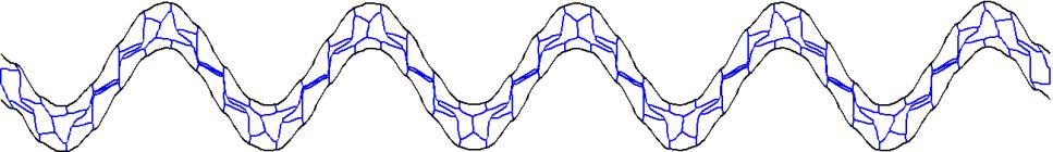
35 CHAPTER 4: IMPLEMENTING OF FINITE ELEMENT MODEL IN MATLAB 4.1 Generating Honeycomb Sandwich Panel Geometry Structure Considering implement a honeycomb sandwich plate geometric structure, there are several parameters which contribute to it. As h, l,, n (number of cells in longitudinal direction) and m(number of cells in transverse direction). Regular and auxetic honeycomb cells can be achieved by changing the h, l and. In the Figure 4.1, those two black lines represent the two face sheet, blue lines show the core part filled with honeycomb cells. Red dots on the figures mean the nodes connected to each beam element. (a) (b) Figure 4.1: Single (a) regular and (b) auxetic honeycomb Since sandwich panels with different numbers of cells are investigated. By inputting the value of m and n in the code, a honeycomb sandwich panels with arbitrary numbers of unit cells can be generated. 3
 before and (b) after mesh In order to make the result more accurate, a")


36 Mesh (a) (b) Figure 4.: Regular double row honeycomb (a) before and (b) after mesh In order to make the result more accurate, a mesh based on the length of beam element is introduced in the sandwich plate model. By changing the seed size, a refine mesh with multiple elements within two connecting nodes is applied. Then the final geometric model is implemented. Honeycomb sandwich plate structure in different orientation can be also achieved in the same way. Figure 4.3: Regular honeycomb of Orientation II 4. Preprocessing In this section of code, the geometric and material properties were defined by input the value of associated parameters. 4
37 Table 4.1: Input parameters for Geometric and Material properties h l Straight member length of honeycomb cell Angle member length of honeycomb cell Internal angle of the honeycomb cell Thickness of the face sheet In-plane thickness of honeycomb cell n m Number of cells in longitudinal direction Number of cells in transverse direction seed The minimum element length Mass density E Young s modulus In this section of the structure of the sandwich plate is defined. The Nodes and Elements matrices are generated which contain the geometry information of the plate. All the nodes on the two ends of the sandwich panels were recorded for boundary condition. And all the elements on the top layer and bottom layer were also captured for further calculation. Table 4.: Nodes and elements matrices x x x x Nodes 1 1 n1 n1 n y y y y n 5 Elements 1 3 mm nn
38 4.3 Process The parameters of geometric and material properties as well as the nodes and elements were used to construct the beam elastic stiffness matrices and mass matrices. Since the cross-section of the beam was considering rectangular, the inertial of moment and area of the cross-section can be calculated as 3 bt I (4.1) 1 A t b (4.) Gaussian Quadrature was applied to approximate the integral in equation 4.1, 4., and 4.3. Four gauss point were used in the work, since the order of polynomial in those equations is 4. Exact solution can be obtained use four points Gaussian Quadrature rule. 4 K EA EI ( N ( x) v N ( x) ) W (4.3) i j j j j i i1 j1 j1 Which x is the gauss points and ( e ) i W is a weight for element e. Gauss ( e ) i points and weight are listed below 6
39 Table 4.3: Gauss points and weight Number of points Points Weights L L L L L L L L L L L L Assemble the element Stiffness matrices and element mass matrices into the global stiffness and mass matrices. The global load vector was also assembled by the element load vector. As shown in the equations below n ( e) K K [ ] (4.4) e1 ( e) M M n [ ] (4.5) e1 n ( e) F F (4.6) e1 The boundary condition were applied after assembling the global matrices, and the u, v of the every nodes on the boundary were fixed to zero. By applying Lagrange equation, the equation of motion for vibration of beam can be derived as below. M x Kx 0 (4.7) The natural frequency can be obtained by Equation 4.8, n represents the nth 7
40 natural frequency. In MATLAB code, the eigen-value (natural frequency) and eigen-vector(degree of freedom at natural frequency) of the stiffness and mass matrices can be approximated using eigs command. K n Mn 0 (4.8) The frequency range studying in this work was 1~1000Hz. All the natural frequencies in this range and seven frequencies between each natural frequency are chosen for frequency response analysis. Substitute those frequencies into equation 4.9, the degree of freedom can be calculated. K M F (4.9) The information of the degree of freedom for every nodes associated with certain frequency was collected and used for further study. 8
41 CHAPTER 5: IMPLEMENTING OF ACOUSTIC FINITE ELEMENT MODEL IN ABAQUS 5.1 Geometric and Material Properties In this work, two parts were used for analysis. The honeycomb sandwich panels which include the two face sheets and core section, the air fluid domain on the transmitted side of sandwich plate. A D planar deformable wire part was modeled for sandwich plate. The core section of each sandwich plate contains 40 cells in x-direction and 1 cell in y-direction or 80 cells in x-direction and cells in y-direction for Orientation I. For Orientation II, there are 40 cells in x-direction and 3 cells in y-direction. The angle of the honeycomb core is varied from 45 to 45. Meanwhile, h, l is determined by the angle and the size of unit cell. To assign the beam property to the plate, two rectangular beam profiles were defined for face sheet and core separately. As a dimension of the profile corresponding to the thickness and was varied from different models. The b dimension represents the out-of-plane length was set to 1 for simplicity. Both the face sheet and core were assigned the material properties of Aluminum with density kg / m, Young s modulus E=71Gpa and Poisson ration v=0.3. The material properties were used for all kind of honeycomb sandwich plate discussed in the work. 9

42 Air Acoustic Impedance Figure 5.1: Analysis model in ABAQUS Sandwich Panel For the air fluid part, an elliptical domain is built to simulate the effects of sound transmission. It is modeled as a D planar deformable shell. A solid, homogenous section was assigned to the air fluid part, with out-of-plane thickness set to 1. Material properties of air with density 3 1. kg / m and Acoustic medium properties of bulk modulus k= (adiabatic) are applied to this part. It is also used for all the cases for the study. A semi-circular domain is also built for selected model for the accuracy study. 5. Mesh B-3 which a node cubic beam elements are assigned for both face sheets and core. It is the same element as we used in MATLAB code. While the B- Quadratic Timoshenko beam elements are also assigned for selected models for validation. A sizing control is applied to ensure at least four elements per shortest edge of the sandwich plate. 30

43 For the air domain, ACD3 which a 3 node triangle acoustic elements were used. Since recommended by ABAQUS documentation, each wave length should consist at least 6-8 elements. Double bias which form the center of the fluid domain and edges were applied to make the result more accurate. The seed size of the elements contact with top face sheet of sandwich plate is Wave length can be obtained through the equation 5.1. c a (5.1) f Considering f as 1000 Hz and 6 elements per wave number [1], thus for the elements at the edge of fluid domain, the seed size is Figure 5.: Mesh of air domain 5.3 Constraints In order to make sure the air fluid domain contact to the sandwich plate, a surface tie constraint was applied. The top face sheet of sandwich plate is set as master surface while the bottom edge of air fluid domain is set as slave surface. By setup the constraint, a fluid-solid coupling was generated to ensure the two parts deformed simultaneously. 31
44 Surface tie Figure 5.3: Constraints between air domain and sandwich plate Considering the sound waves may reflect off the top surface edge of the fluid domain back to the air region. An acoustic impedance interaction on the top edge of fluid part was defined to prevent the reflection. The acoustic impedance is set as non-reflecting and geometry as Elliptical. The Axis length is given the value, the Eccentricity is set as , the center coordinates is set as 1, , 0 which is the center of the top face sheet, and the direction cosine as 1, 0, Boundary Condition and Load Since the sandwich plate is pinned to a rigid baffle on both sides, all the nodes on the ends of the plate were selected and their U1 (displacement in x-direction) and U (displacement in y-direction) were set to fixed as 0. To simulate the incident sound pressure wave, a unit amplitude pressure load was applied to the bottom face sheet. For simplicity, all the value of pressure were set to 1 pa and direct applied to the panel. 3
45 Pinned Pinned Unit pressure load Figure 5.4: Boundary conditions and load 5.5 Natural Frequency Extraction Procedure In the natural frequency extraction procedure, only the sandwich plate part is used for analysis. A frequency linear perturbation procedure was chose which maximum frequency of interest is set to Since the 1~1000 Hz is the frequency range discussed in the work. By executing the procedure, all the natural frequencies in the range can be obtained. 5.6 Steady State Dynamic, Direct Procedure Both the sandwich plate part and air fluid part were used for the sound pressure loss study. In order to collect the history air pressure data of top face sheet, a set which contain all the air nodes contact to the top face of sandwich plate was defined. The air pressure of every node in the air fluid domain was collected as a field output. A steady-state dynamics, direct procedure was defined for analysis. The scale was set to logarithmic, and the natural frequencies obtained by last procedure were used as Lower frequency and upper frequency. The number of frequency between each 33
46 natural frequency was set to 7, while the bias was given the value. Figure 5.5: Steady-state dynamic, direct step 34
47 CHAPTER 6: NATURAL FREQUENCIES ANALYSIS FOR SANDWICH PANELS WITH VARYING CORE GEOMETRY 6.1 Geometry Parameters and Effective Properties The honeycomb models tested consist of cores that contain either 40 cells in the longitudinal direction and 1 cell in transverse direction or 80 cells in longitudinal direction and cells in transverse directions for orientation I. For orientation II there will be 40 cells in a row and 3 cells in a column. The models range from 45 to 45 with increment of 5 for Orientation I 40x1 cells and 15 for others. Between each models, the l and h are varied in order to keep the overall size of the unit cells the same using the size controlling method discussed in chapter 3. The thickness of the cell walls is also varied to ensure that all the models have same effective mass property. Thus keep constant mass for every model. The geometric properties of all the models studied in this work are listed in Table 4.1, Table 4. and Table 4.3 below. For all of the models, a face sheet thickness of.5 mm is used. 35
48 Table 6.1: Geometries and effective properties of Orientation I 40x1 cells Cell Angle l (mm) h (mm) t (mm) * G 1 (Mpa) * E 1 (Mpa) * E * ρ 3 (Mpa) ( Kg m ) D 11 3 (Mpa m ) D 66 3 (Mpa m )
49 Table 6.: Geometries and effective properties of Orientation I 80x cells Cell Angle l (mm) h (mm) t (mm) * G 1 (Mpa) * E 1 (Mpa) * E * ρ 3 (Mpa) ( Kg m ) D 11 3 (Mpa m ) D 66 3 (Mpa m ) Table 6.3: Geometries and effective properties of Orientation II 40x3 cells Cell Angle l (mm) h (mm) t (mm) * G 1 (Mpa) * E 1 (Mpa) * E * ρ 3 (Mpa) ( Kg m ) D 11 3 (Mpa m ) D 66 3 (Mpa m )
50 l (mm) h (mm) Figures below illustrate the relation between the geometric parameter h, l, thickness t and cell angle. With the increase of the internal cell angle from negative to positive, the lengths of h, l also decrease. For the in-plane thickness, its value increase first and reach the maximum at Orientation I 40x1 Orientation I 80x Orientation II 40x Cell Angle ( ) Figure 6.1: Straight member length h Vs varying cell angles Layout I 40x1 5 Layout I 80x Layout II 40x Cell Angle ( ) Figure 6.: Angle member length l Vs varying cell angles 38
51 t (mm) Orientation I 40x1 0.5 Orientation I 80x Orientation II 40x Cell Angle ( ) Figure 6.3: Cell thickness t Vs varying cell angles Observation for the relation between internal cell angle and effective properties is also made. The effective shear modulus increase along with the increase of cell angle, while the gradient of the G 1 Vs angle curve also becomes larger and larger. For E 1 effective modulus in longitudinal direction, it increase as the increase of cell angle of negative angle models while decrease for the positive angle model. For the effective modulus E, it increases first to a maximum value at 0 model, then decreases. The results of effective bending and in-plane stiffness is similar to the G 1 and E 1. With the increase of the cell angle the G1 contribute more to the A
52 (Mpa) (Mpa) Negative angle Positive angle Cell Angle ( ) Figure 6.4: Effective shear modulus Vs varying cell angles negative angle positive angle Cell Angle ( ) Figure 6.5: Effective Young s modulus of transverse direction Vs varying cell angles 40
53 (Mpa) Negative angle Positive angle Cell Angle ( ) Figure 6.6: Effective Young s modulus of longitudinal direction Vs varying cell angles 6. Comparison of ABAQUS and MATLAB Results Before listing all the natural frequencies for the different geometries above, a comparison of ABAQUS and MATLAB results is made to verify the accuracy of MATLAB code. The 30 and -30 angle honeycomb structure of Orientation I 40x1 cells are chose for verification. As shown in the Table 4.4 and Table 4.5, there are only slight differences between the ABAQUS and MATLAB results. The deviation is only 0.1 % for the first natural frequency of 30 panel and even as low as 0.01% for 10 th natural frequency. For the - 30 plate, the deviation is no more than 1 %. 41
54 Table 6.4: Comparison of first ten natural frequencies for Orientation I 40x1 honeycomb core Mode Bernoulli beam MATLAB Deviation % % % % % % % % % % Table 6.5: Comparison of first ten natural frequencies for Orientation I 40x1 honeycomb core Mode Bernoulli beam MATLAB Deviation % % % % % % % % % % The ABAQUS results using quadratic Timoshenko beam elements are also used for comparison as shown in Table 6.6 and 6.7. The deviations of results are higher than the cubic Bernoulli beam ones. The highest deviation occurs at the 10 th natural frequency of 30 honeycomb core which is no more than %. 4
55 Table 6.6: Comparison of first ten natural frequencies for Orientation I 40x1 honeycomb core Mode Timoshenko Beam MATLAB Deviation % % % % % % % % % % Table 6.7: Comparison of first ten natural frequencies for Orientation I 40x1 honeycomb core Mode Timoshenko Beam MATLAB Deviation % % % % % % % % % % 6.3 Natural Frequencies Result The first ten modes and their corresponding frequencies are shown below in Table 4.6 (orientation I 40x1), Table 4.7 (orientation I 80x) and Table 4.8 (orientation II 40x3). The later natural frequencies tend to lose the accuracy, so only the first ten natural frequencies are used for analysis. 43
56 Table 6.8: Natural frequencies of orientation I 40x1 Mode The lowest first modal frequency for the honeycomb core sandwich panels occurs on 1.31 Hz, which is for the 45 model. The first natural frequency increases as the increase of internal cell angles of each model. The highest first natural frequency occurs at Hz, which is for the 45 model. It can be observed that when the internal angle of honeycomb sandwich plate becomes less negative, the first natural frequency will increase. And the spacing between frequencies in the Hz range will also become larger when the internal angle increases for both regular and auxetic model. Additionally, there will be more numbers of natural frequencies in certain range, if the internal angle is smaller. 44
57 Table 6.9: Natural Frequencies of Orientation I 80x Mode Table 6.10: Natural Frequencies of Orientation II 40x3 Mode Compare to the Orientation I 40x1 cells models, the Orientation I 80x cells and Orientation II 40x3 cells models show the same trends. Besides that, the results of those models are very close to the Orientation I 40x1 cells models. The first natural frequency of 30 Orientation I 80x and Orientation II 40x3 honeycomb sandwich panels occur at 60. Hz and Hz which are near to the 30 40x1 one. Theoretically, they may have the same natural frequencies, because their effective properties are same. However, because the different length of parts that connect the 45
58 Frequency (Hz) face sheet and honeycomb core, there may be a little disparity for the three models. Figure shows the trends of first natural frequency for models of orientation I 40x1cells with internal angles Cell Angle ( ) Figure 6.7: First natural frequency Vs varying cell angles 6.4 Relations of Effective Properties and Natural Frequencies In order to analysis the influence of effective property on the natural frequency for honeycomb sandwich plate, the first natural frequency and corresponding effective properties of honeycomb sandwich plate with different internal angle are plotted in Figure 6.8, 6.9, All the models chose here contain 40x1 cells in orientation I, since the Orientation I 80x and Orientation II 40x3 cells models share the same effective properties. 46
59 Frequency (Hz) Frequency (Hz) Negative angle Positive angle Figure 6.8: First natural frequency Vs Effective Shear Modulus Negative angle Positive angle Figure 6.9: First natural frequency Vs Effective Young s Modulus in longitudinal direction 47
60 Frequency ((Hz) Negative angle Positive angle Figure 6.10: First natural frequency Vs Effective Young s Modulus of transverse direction As shown in the Figures above, the first natural frequency changes with the variation of effective properties. For effective shear modulus, honeycomb sandwich plate with larger shear modulus has a higher first natural frequency. And the shear modulus change more rapidly for the positive angle honeycomb cores. For the effective material in longitudinal direction, the behavior of the positive and negative angle models mirrors each other. Panels with positive angles have a higher natural frequency for smaller E 1. On the contrary, with the increase of the E 1 the first natural frequencies become higher for negative angle models. The E for negative angle is increased with the increase of the frequencies, while for positive angle it increase first to certain value then decrease as the increase of the first natural frequency. Generally, E 1 and G 1 tend to be more sensitive to the change of natural frequencies. 48
61 6.5 Mode Shape Mode Hz Mode 13.0 Hz Mode Hz Mode Hz Mode Hz Mode Hz Mode Hz Mode Hz Mode Hz Mode Hz Figure 6.11: First ten mode shape of orientation I 40x1 cells panel of 49
62 For the first two frequencies, the honeycomb core deformed in pattern, each unit of the honeycomb structure can be identified. The two face sheet and honeycomb core bend together. With the increase of the value of the natural frequency, the deformation of the core section becomes more intense and the shape of each unit can be hardly distinguished. The numbers of wave peaks match the number the mode shape, which means the nth mode shape contains n wave peaks. Noticed that, the mode 10 is a dilatational mode which means the two face sheet bend in opposite direction. It is occurred at a higher frequency. Table 6.11: First natural frequencies of dilatational mode shape with vary cells Cell angle units Frequency (Hz) 40x x x x x x x x x x
63 Figure 6.1 shows the selected dilatational mode shapes for the o -30 Orientation I 40x1 cells model. The each two face sheets of the sandwich panels bend in opposite direction. However there are some differences among those mode shapes. For mode 1 at Hz the honeycomb core deforms to one end of the panel. For the mode 4 at 75.8 Hz, the upside of the core deforms to the left while the bottom side deforms to right. When the frequency increases to Hz, the deformation of the panel is symmetric in longitudinal direction, the left part of panel deforms to the left and the right part to the right. The effects of the dilatational vibration on the structural and acoustic performance of honeycomb sandwich panels are discussed in Chapter 7. Mode Hz Mode Hz Mode Hz Mode Hz Figure 6.1: Selected dilatational mode shapes of - Orientation I 40x1 cells 51
64 CHAPTER 7: STRUCTURAL-ACOUSTIC PERFORMANCE OF SANDWICH PANELS 7.1 Structural Response Root Mean Square Velocity along the transverse direction is chosen as the measurement of the response of the top face sheet [15]. It is related to the energy of the motion and transmitted sound pressure level in the air domain. It can be derived as 1 L Vrms ( V t ) 0 t V dx L (7.1) Which Vt iw t and Vt iw t in equation 7.1 are complex conjugates Substitute V t and V t into the equation (7.1) V rms L W 0 t dx L (7.) Which W t is the transverse displacement of the top face sheet. The integral over the length of the top face can be evaluated as the sum of integrals over every element on it. A damping ratio 0.01 is introduced by setting a complex modulus E (1 i ) E [5].Then imposing the shape function defined in chapter and the element nodal degrees of freedom solved in the chapter 4. The equation (7.4) can be expressed as N ( k ) L k k vrms ( N ( ) 0 j x v j N j( x) j ) dx L k1 j1 (7.3) The intensity I rms is defined to transfer the V rms in db scale as I rms V rms 0log10 V0 (7.4) 5
65 Irms (db) Where V m s is a reference velocity [15] Mode Mode 3 Mode 5 Mode 7 Mode Frequency (Hz) Figure 7.1: of orientation I 40x1 structure with angle As shown in Figure 7.1, the each peak in the curve are corresponding the odd number of natural frequencies. At these frequencies, the structure vibrates more intense than other frequencies. Within each interval, the Irms decreases to certain level then increase again to the next peak. Generally, the vibration of the plate decreases with the rise of the frequencies at the resonance control frequency range. 53
66 Irms (db) Pos 15 Pos 45 Pos Frequency (Hz) Figure 7.: for orientation I 40x1 structure with positive angle The Figure 7. shows the results for honeycomb sandwich structure for Orientation I with positive internal angles. 15, 30, 45 were chose to represent different angles. General trends for all the three models are same. While the first peak occurs at a lower frequency level with smaller positive internal angle. The spacing between each peaks of smaller angles are also smaller than those with greater angles. 54
67 Irms (db) Irms (db) Neg 45 Neg 30 Neg Frequency (Hz) Figure 7.3: for Orientation I 40x1 structure with negative angle Similar trends can be also observed for honeycomb sandwich plate with negative internal angles. The 45 exhibits the lowest frequency for first peak, and smallest spacing between each peaks Neg 30 Pos Frequency (Hz) Figure 7.4: for Orientation I 40x1 with different angle 55
68 Irms (db) Comparison of sandwich plate with negative and positive internal angles is shown in Figure and 30 are chose to represent positive and negative angle. Except for the first peaks, the positive angle plate tends to have more vibration at each peak than negative ones. And the spacing between each peaks of positive plate is also larger than negative plate. The results prove that if the honeycomb sandwich panels with different internal angles have the same mass properties, they will exhibit similar vibration behaviors Frequency (Hz) Figure 7.5: for different orientation with angle Comparison of sandwich plate with same internal angle but different Orientation is also made which results are shown in Figure 7.5. All the three models exhibit the same trends. The first peak of the three models occurs at nearly the same frequencies, while the spacing between each peak is varied for these models. The Orientation I 40x1 cells model has the greatest spacing, and the Orientation II 40x3 has the smallest one. All the three models have the similar intensity of vibration. 56
69 7. Sound Transmission Loss There are many expressions for the sound transmission loss of sandwich plate. Equation 7.5 [1] is used to calculate the sound transmission loss. Pt is the square root summation of air pressure for all the nodes on the top face sheet. While Pi is the square root of the incident pressure times the Nt total numbers of nodes on the top face sheet. P i STL 10 log10 P t (7.5) t P P P P (7.6) 1 P N * f (7.7) i t n 7..1 Model Accuracy A mesh convergence and air domain shape study are made to investigate if the ellipse air domain is accurate enough to describe the sound transmission loss. Figure 7.7 shows the sound transmission results of a fine mesh (seed size 0.04 at the edge of air domain) and a coarse mesh (seed size 0.08 the edge of air fluid domain). As illustrated in the Figure 7.6, the STL curve of fine mesh is smoother than the coarse mesh one at higher frequencies, while there is not much difference at the low frequency range. For the comparison of semi-circle and elliptical domain with same longitudinal length, the curve of semi-circle appears more continuous at very low frequency. However, there is not much deviation between the semi-circle and elliptical domain. Thus, the elliptical domain can be used to reduce the analysis time. 57
70 STL (db) STL (db) Coarse mesh Fine mesh Frequency (Hz) Figure 7.6: STL results of fine and coarse mesh Semi-circle Ellipse Frequency (Hz) Figure 7.7: STL results of Semi-circle and Ellipse domain with same longitudinal length 7.. Sound Transmission Results with Various Configurations As shown in Figure 7.8, the odd numbers of natural frequencies correspond to the 58
71 STL (db) each dips in the curve, which means there will be less transmission lose at these frequencies Mode 5 Mode 7 Mode 9 Mode 3 Mode Frequency (Hz) Figure 7.8: STL for Orientation I 40x1 structure with angle o The15 model has a lowest frequency for first dip and smallest spacing between each dip. Notice that, around 790 Hz, there is an unusual dip occurs for o 15 model. The sound transmission loss at this frequency soundly decreases to a very low level. It may because at that frequency, the two face sheet of sandwich plate vibrates at same direction and the plate performs a dilatational mode shape. 59
72 STL (DB) STL (DB) Pos 30 Pos 45 Pos Frequency (Hz) Figure 7.9 STL for Orientation I 40x1 structure with positive angle Neg 45 Neg 30 Neg Frequency (Hz) Figure 7.10: STL for Orientation I 40x1 structure with negative angle Figure 7.1 shows a comparison of o 30 and o -30 honeycomb sandwich plate with Orientation I 40x1 cells. The first dip occurs only for o -30 model corresponding to the first natural frequency. In addition the o -30 model have more 60
73 STL (DB) dips than the 30 model, overall, the STL for 30 model is more than 30 model, which means there will be more loss of acoustic energy Pos 30 Neg Frequency (Hz) Figure 7.11: STL for Orientation I 40x1 structure with different angle A comparison for models with different orientation is also been made for 30 models. They have almost the same effective properties. Thus, two models have similar sound transmission curves. However the curve for Orientation II 40x3 model shifts a little to the left, which also matches the slight difference of natural frequencies for those two models. A similar observation is made by compare the 30 models, it shows the same trends as the 30 ones. 61
74 STL (db) STL (db) Orientation I 40x1 Orientation I 80x Orientation II 40x Frequency (Hz) Figure 7.1: STL for different orientation with angle Orientation I 40x1 Orientation II 40x3 Orientation II 80x Frequency (Hz) Figure 7.13: STL for different orientation with angle 6
75 Irms (db) 7.3 Comparsion and Discussion 0 Frequency (Hz) Figure 7.14: results with reverse axis The trends of I rms can reflect the trend of sound transmission loss. The Figure show the I rms curve of 30 orientation I 40x1 model with reverse axis of I rms. The peaks of I rms curves turn into dips, which is similar to the sound transmission curves. And with the increase of the frequency the overall vibration of the sandwich panels decrease as well as the value of the peaks. While the sound transmission loss of the sandwich panels also increases as the increase of value of the dips. A comparison of the 30 Orientation I 40x1 sandwich panels with different thickness was made to demonstrate the influence of effective properties on vibration behavior. As illustrate in the Figure 7.5. Since the panel with 1.5mm in-plane thickness of honeycomb core is less stiff than the.5mm ones. The first peak of I rms curve occurs at a lower frequency for the sandwich panel with 1.5 mm thickness. And it tends to have more peaks within the range. Additionally, the Irms appears to be 63
76 Irms (db) more intense than the thicker one t=1.5 mm t=.5 mm t=3.5 mm Frequency (Hz) Figure 7.15: for orientation I 40x1 cells with angle with different in-plane thicknesses A comparison of the sound transmission loss of o 30 angle honeycomb structure with same geometry parameters except thickness was made. The thickness chose in this work is.5 mm and 3.5 mm. The overall sound transmission of 3.5 mm model is more than.5 mm one. There are less dips in the frequency range for the 3.5 mm models, since it s stiffer than.5 mm model. As discussed in chapter 1, the heavier the sandwich panel is, the more sound transmission loss is obtained. 64
77 STL (db) t=.5 mm t= 3.5 mm Frequency (Hz) Figure 7.16: STL of the Orientation I 40x1 cell with different in-plane thicknesses As discussed before the model with increased internal angles have a higher first natural frequency and more spacing between the peaks on the I rms curve and dips on the sound transmission curve. As illustrated in Table 7.1, the o 30 model has the lowest the first natural frequency 1.31 Hz and smallest spacing 1.11 Hz, while the o 45 has the highest first frequency Hz. Due to the differences of truncation parts, there are slight deviation between the Orientation I 40x1 cell model and Orientation I 80x cell, Orientation II 40x3 models. For orientation I the truncation parts of 40x1 cell model is thicker than the 80x cell model, which means it is stiffer and has a higher first frequency and larger spacing. For orientation II the truncation parts is thinner than the orientation I 40x1 cell model, thus it has lower first natural frequency and smaller spacing which is similar to the orientation I 80x cell model. 65
78 Table 7.1: First natural frequency and spacing between peaks on curve of various core configurations Cell angle Unit First natural frequency Spacing between first two peaks 40x x x x x x x x x x The sound transmission loss values of different models are calculated using a metric as areas under the sound transmission curve. As shown in the Table 7., the o -45 model has the smallest sound transmission loss in the stiffness control region while the o 45 model has the largest one. For the total transmission loss, the sandwich panels with auxetic honeycomb core structure tend to have more sound transmission loss than the regular ones for both orientation I and II. Because the truncation part of auxetic honeycomb core sandwich panel has more weight than the regular ones which lead to a heavier weight, therefore more transmission can be achieved. However there is not much difference between the orientation I 40x1 cell 66
79 models and 80x cell models, since they have the similar weight. Total transmission of orientation II are also similar to the orientation I, since the weight of their truncation parts are almost the same. Table 7.: Areas under sound transmission curve Cell angle Unit Stiffness area Resonance area Total area 40x x x x x x x x x x Acoustic Pressure Distributions To visualize the sound radiation effects in the air fluid domain. Sound pressure level is introduced to describe the effective sound pressure. The sound pressure level is defined as p SPL 0log 10 p ref (7.8) 67
80 In this equation, P ref is the standard reference pressure and given the value 0 for air. The corresponding decibel value of incident pressure on the bottom face sheet with 1 Pa is 94 db. Figure below shows the comparisons of SPL distribution between honeycomb sandwich panels with different angle. The sound pressure values of all the nodes in the air fluid domain were collected and imported to MATLAB for SPL calculation. 68
")


81 f=07 Hz SPL (db) f=58 Hz f=847 Hz Figure 7.17: Sound pressure level of panel with Orientation I 40x1 cells 69


82 f=13 Hz SPL (db) f=550 Hz f=89 Hz Figure 7.18: Sound pressure level of - panel with Orientation I 40x1 cells 70
83 Frequencies at the dips of the sound transmission loss curve are used for analysis. One observation of the sound pressure level is at the low frequency range, the overall pressure level is greater than high frequency range. The pressure levels of 30 model at 07 Hz are greater than 70 db at most area of air domain as well as the 30 model. With the increase of the frequencies, the sound pressure level also decrease corresponding to the STL cure. The high SPL region only appears close to the top face sheet of the sandwich plate. Another observation is for the two approximate frequencies between 30 and - 30 models, the - 30 model has smaller SPL, which verifies the I rms and STL results for these two models. In addition, there are also some radiate lines spread in the air fluid domain, which have a lower pressure level than other regions. The number and shape of those lines may determined by their mode shapes. Within those lines, the honeycomb will vibrate more, thus more acoustic energy will lose and lead to a low sound pressure level. For the 30 model at 58 Hz (7 th mode), the air domain is divided into 7 parts by 6 lines which is same as the summation of peak and dip numbers of mode shape. 71


84 SPL (db) f=770 Hz f=919 Hz Figure 7.19: Radiated sound pressure level of panel with Orientation I 40x1 at selected frequency with dilatational mode shapes The sound pressure level of the o -30 model on the natural frequencies with dilatational mode shapes at dip of the sound transmission curve is plotted in Figure One observation is the mode shape has a influence on the distribution of sound pressure. For 770 Hz, the panel vibrates less in the center and become more intense towards the end, thus the sound pressure level in the center is high and lower at the end. Similar trends can be observed at 919 Hz, the sound pressure level is high at the 7
VIBRATION AND ACOUSTIC PROPERTIES OF HONEYCOMB SANDWICH STRUCTURES SUBJECT TO VARIABLE INCIDENT PLANE-WAVE ANGLE PRESSURE LOADS
 Clemson University TigerPrints All Theses Theses 5-2013 VIBRATION AND ACOUSTIC PROPERTIES OF HONEYCOMB SANDWICH STRUCTURES SUBJECT TO VARIABLE INCIDENT PLANE-WAVE ANGLE PRESSURE LOADS Jiaxue Yan Clemson
Finite Element Modeling and Design of Honeycomb Sandwich Panels for Acoustic Performance
 Clemson University TigerPrints All Theses Theses 5-2012 Finite Element Modeling and Design of Honeycomb Sandwich Panels for Acoustic Performance David Griese Clemson University, d.c.griese@gmail.com Follow
FINITE ELEMENT ANALYSIS OF EFFECTIVE MECHANICAL PROPERTIES, VIBRATION AND ACOUSTIC PERFORMANCE OF AUXETIC CHIRAL CORE SANDWICH STRUCTURES
 Clemson University TigerPrints All Theses Theses 8-2013 FINITE ELEMENT ANALYSIS OF EFFECTIVE MECHANICAL PROPERTIES, VIBRATION AND ACOUSTIC PERFORMANCE OF AUXETIC CHIRAL CORE SANDWICH STRUCTURES Hrishikesh
Composite Sandwich Structures with Honeycomb Core subjected to Impact
 Clemson University TigerPrints All Theses Theses 12-212 Composite Sandwich Structures with Honeycomb Core subjected to Impact Lei He Clemson University, he6@clemson.edu Follow this and additional works
Structural Dynamics Lecture Eleven: Dynamic Response of MDOF Systems: (Chapter 11) By: H. Ahmadian
 By: H. Ahmadian") Structural Dynamics Lecture Eleven: Dynamic Response of MDOF Systems: (Chapter 11) By: H. Ahmadian ahmadian@iust.ac.ir Dynamic Response of MDOF Systems: Mode-Superposition Method Mode-Superposition Method:
Structural Dynamics Lecture Eleven: Dynamic Response of MDOF Systems: (Chapter 11) By: H. Ahmadian ahmadian@iust.ac.ir Dynamic Response of MDOF Systems: Mode-Superposition Method Mode-Superposition Method:
ME 475 Modal Analysis of a Tapered Beam
 ME 475 Modal Analysis of a Tapered Beam Objectives: 1. To find the natural frequencies and mode shapes of a tapered beam using FEA.. To compare the FE solution to analytical solutions of the vibratory
ANALYTICAL SOLUTIONS USING HIGH ORDER COMPOSITE LAMINATE THEORY FOR HONEYCOMB SANDWICH PLATES WITH VISCOELASTIC FREQUENCY DEPENDENT DAMPING
 Clemson University TigerPrints All Theses Theses 8-11 ANALYTICAL SOLUTIONS USING HIGH ORDER COMPOSITE LAMINATE THEORY FOR HONEYCOMB SANDWICH PLATES WITH VISCOELASTIC FREQUENCY DEPENDENT DAMPING Nan Shan
Optimization for heat and sound insulation of honeycomb sandwich panel in thermal environments
 Optimization for heat and sound insulation of honeycomb sandwich panel in thermal environments Jinlong Yuan 1, Haibo Chen 2, Qiang Zhong 3, Kongjuan Li 4 Department of Modern mechanics, University of Science
Viscoelastic Damping of Hexagonal Honeycomb Sandwich Panels
 Clemson University TigerPrints All Theses Theses 8-2011 Viscoelastic Damping of Hexagonal Honeycomb Sandwich Panels Nikhil Seera Clemson University, nseera@clemson.edu Follow this and additional works
Using MATLAB and. Abaqus. Finite Element Analysis. Introduction to. Amar Khennane. Taylor & Francis Croup. Taylor & Francis Croup,
 Introduction to Finite Element Analysis Using MATLAB and Abaqus Amar Khennane Taylor & Francis Croup Boca Raton London New York CRC Press is an imprint of the Taylor & Francis Croup, an informa business
UNCONVENTIONAL FINITE ELEMENT MODELS FOR NONLINEAR ANALYSIS OF BEAMS AND PLATES
 UNCONVENTIONAL FINITE ELEMENT MODELS FOR NONLINEAR ANALYSIS OF BEAMS AND PLATES A Thesis by WOORAM KIM Submitted to the Office of Graduate Studies of Texas A&M University in partial fulfillment of the
Generic Strategies to Implement Material Grading in Finite Element Methods for Isotropic and Anisotropic Materials
 University of Nebraska - Lincoln DigitalCommons@University of Nebraska - Lincoln Engineering Mechanics Dissertations & Theses Mechanical & Materials Engineering, Department of Winter 12-9-2011 Generic
Mechanics of Irregular Honeycomb Structures
 Mechanics of Irregular Honeycomb Structures S. Adhikari 1, T. Mukhopadhyay 1 Chair of Aerospace Engineering, College of Engineering, Swansea University, Singleton Park, Swansea SA2 8PP, UK Sixth International
Comparison of Unit Cell Geometry for Bloch Wave Analysis in Two Dimensional Periodic Beam Structures
 Clemson University TigerPrints All Theses Theses 8-018 Comparison of Unit Cell Geometry for Bloch Wave Analysis in Two Dimensional Periodic Beam Structures Likitha Marneni Clemson University, lmarnen@g.clemson.edu
Presented By: EAS 6939 Aerospace Structural Composites
 A Beam Theory for Laminated Composites and Application to Torsion Problems Dr. BhavaniV. Sankar Presented By: Sameer Luthra EAS 6939 Aerospace Structural Composites 1 Introduction Composite beams have
COPYRIGHTED MATERIAL. Index
 Index A Admissible function, 163 Amplification factor, 36 Amplitude, 1, 22 Amplitude-modulated carrier, 630 Amplitude ratio, 36 Antinodes, 612 Approximate analytical methods, 647 Assumed modes method,
Table of Contents. Preface... 13
 Table of Contents Preface... 13 Chapter 1. Vibrations of Continuous Elastic Solid Media... 17 1.1. Objective of the chapter... 17 1.2. Equations of motion and boundary conditions of continuous media...
1859. Forced transverse vibration analysis of a Rayleigh double-beam system with a Pasternak middle layer subjected to compressive axial load
 1859. Forced transverse vibration analysis of a Rayleigh double-beam system with a Pasternak middle layer subjected to compressive axial load Nader Mohammadi 1, Mehrdad Nasirshoaibi 2 Department of Mechanical
Structural-acoustic optimization of 2-D Gradient Auxetic Sandwich Panels
 : 2 nd Euro-Mediterranean Conference 25-27 Apr 2017 on Structural Dynamics and Vibroacoustics Sevilla (Spain) Structural-acoustic optimization of 2-D Gradient Auxetic Sandwich Panels Mohammad Sadegh Mazloomi
Bending of Simply Supported Isotropic and Composite Laminate Plates
 Bending of Simply Supported Isotropic and Composite Laminate Plates Ernesto Gutierrez-Miravete 1 Isotropic Plates Consider simply a supported rectangular plate of isotropic material (length a, width b,
Computational Modelling of Vibrations Transmission Loss of Auxetic Lattice Structure
 Vibrations in Physical Systems Vol. 27 (2016) Abstract Computational Modelling of Vibrations Transmission Loss of Auxetic Lattice Structure Eligiusz IDCZAK Institute of Applied Mechanics, Poznan University
Study on the influence of design parameter variation on the dynamic behaviour of honeycomb sandwich panels
 Study on the influence of design parameter variation on the dynamic behaviour of honeycomb sandwich panels Stijn Debruyne 2, Dirk Vandepitte 1, Eric Debrabandere 2, Marc Hongerloot 2 1 Department of Mechanical
Lecture 15 Strain and stress in beams
 Spring, 2019 ME 323 Mechanics of Materials Lecture 15 Strain and stress in beams Reading assignment: 6.1 6.2 News: Instructor: Prof. Marcial Gonzalez Last modified: 1/6/19 9:42:38 PM Beam theory (@ ME
CHAPTER 14 BUCKLING ANALYSIS OF 1D AND 2D STRUCTURES
 CHAPTER 14 BUCKLING ANALYSIS OF 1D AND 2D STRUCTURES 14.1 GENERAL REMARKS In structures where dominant loading is usually static, the most common cause of the collapse is a buckling failure. Buckling may
The Finite Element Method for Solid and Structural Mechanics
 The Finite Element Method for Solid and Structural Mechanics Sixth edition O.C. Zienkiewicz, CBE, FRS UNESCO Professor of Numerical Methods in Engineering International Centre for Numerical Methods in
BHAR AT HID AS AN ENGIN E ERI N G C O L L E G E NATTR A MPA LL I
 BHAR AT HID AS AN ENGIN E ERI N G C O L L E G E NATTR A MPA LL I 635 8 54. Third Year M E C H A NICAL VI S E M ES TER QUE S T I ON B ANK Subject: ME 6 603 FIN I T E E LE ME N T A N A L YSIS UNI T - I INTRODUCTION
DHANALAKSHMI COLLEGE OF ENGINEERING, CHENNAI DEPARTMENT OF MECHANICAL ENGINEERING ME 6603 FINITE ELEMENT ANALYSIS PART A (2 MARKS)
") DHANALAKSHMI COLLEGE OF ENGINEERING, CHENNAI DEPARTMENT OF MECHANICAL ENGINEERING ME 6603 FINITE ELEMENT ANALYSIS UNIT I : FINITE ELEMENT FORMULATION OF BOUNDARY VALUE PART A (2 MARKS) 1. Write the types
DHANALAKSHMI COLLEGE OF ENGINEERING, CHENNAI DEPARTMENT OF MECHANICAL ENGINEERING ME 6603 FINITE ELEMENT ANALYSIS UNIT I : FINITE ELEMENT FORMULATION OF BOUNDARY VALUE PART A (2 MARKS) 1. Write the types
JEPPIAAR ENGINEERING COLLEGE
 JEPPIAAR ENGINEERING COLLEGE Jeppiaar Nagar, Rajiv Gandhi Salai 600 119 DEPARTMENT OFMECHANICAL ENGINEERING QUESTION BANK VI SEMESTER ME6603 FINITE ELEMENT ANALYSIS Regulation 013 SUBJECT YEAR /SEM: III
Esben Byskov. Elementary Continuum. Mechanics for Everyone. With Applications to Structural Mechanics. Springer
 Esben Byskov Elementary Continuum Mechanics for Everyone With Applications to Structural Mechanics Springer Contents Preface v Contents ix Introduction What Is Continuum Mechanics? "I Need Continuum Mechanics
CIVL 8/7117 Chapter 12 - Structural Dynamics 1/75. To discuss the dynamics of a single-degree-of freedom springmass
 CIV 8/77 Chapter - /75 Introduction To discuss the dynamics of a single-degree-of freedom springmass system. To derive the finite element equations for the time-dependent stress analysis of the one-dimensional
202 Index. failure, 26 field equation, 122 force, 1
 Index acceleration, 12, 161 admissible function, 155 admissible stress, 32 Airy's stress function, 122, 124 d'alembert's principle, 165, 167, 177 amplitude, 171 analogy, 76 anisotropic material, 20 aperiodic
VIBRATION AND DAMPING ANALYSIS OF FIBER REINFORCED COMPOSITE MATERIAL CONICAL SHELLS
 VIBRATION AND DAMPING ANALYSIS OF FIBER REINFORCED COMPOSITE MATERIAL CONICAL SHELLS Mechanical Engineering Department, Indian Institute of Technology, New Delhi 110 016, India (Received 22 January 1992,
Geometrically exact beam dynamics, with and without rotational degree of freedom
 ICCM2014 28-30 th July, Cambridge, England Geometrically exact beam dynamics, with and without rotational degree of freedom *Tien Long Nguyen¹, Carlo Sansour 2, and Mohammed Hjiaj 1 1 Department of Civil
Sound radiation and sound insulation
 11.1 Sound radiation and sound insulation We actually do not need this chapter You have learned everything you need to know: When waves propagating from one medium to the next it is the change of impedance
Level 7 Postgraduate Diploma in Engineering Computational mechanics using finite element method
 9210-203 Level 7 Postgraduate Diploma in Engineering Computational mechanics using finite element method You should have the following for this examination one answer book No additional data is attached
VIBRATION ENERGY FLOW IN WELDED CONNECTION OF PLATES. 1. Introduction
 ARCHIVES OF ACOUSTICS 31, 4 (Supplement), 53 58 (2006) VIBRATION ENERGY FLOW IN WELDED CONNECTION OF PLATES J. CIEŚLIK, W. BOCHNIAK AGH University of Science and Technology Department of Robotics and Mechatronics
D : SOLID MECHANICS. Q. 1 Q. 9 carry one mark each.
 GTE 2016 Q. 1 Q. 9 carry one mark each. D : SOLID MECHNICS Q.1 single degree of freedom vibrating system has mass of 5 kg, stiffness of 500 N/m and damping coefficient of 100 N-s/m. To make the system
Note that W is the skin surface weight density in units of psf. An equivalent graph in terms of metric units is given in Appendix A.
 VIBRATION RESPONSE OF A CYLINDRICAL SKIN TO ACOUSTIC PRESSURE VIA THE FRANKEN METHOD Revision H By Tom Irvine Email: tomirvine@aol.com September 16, 2008 Introduction The front end of a typical rocket
Chapter 2: Rigid Bar Supported by Two Buckled Struts under Axial, Harmonic, Displacement Excitation..14
 Table of Contents Chapter 1: Research Objectives and Literature Review..1 1.1 Introduction...1 1.2 Literature Review......3 1.2.1 Describing Vibration......3 1.2.2 Vibration Isolation.....6 1.2.2.1 Overview.
Contents as of 12/8/2017. Preface. 1. Overview...1
 Contents as of 12/8/2017 Preface 1. Overview...1 1.1 Introduction...1 1.2 Finite element data...1 1.3 Matrix notation...3 1.4 Matrix partitions...8 1.5 Special finite element matrix notations...9 1.6 Finite
Influence of residual stresses in the structural behavior of. tubular columns and arches. Nuno Rocha Cima Gomes
 October 2014 Influence of residual stresses in the structural behavior of Abstract tubular columns and arches Nuno Rocha Cima Gomes Instituto Superior Técnico, Universidade de Lisboa, Portugal Contact:
Finite Element Method-Part II Isoparametric FE Formulation and some numerical examples Lecture 29 Smart and Micro Systems
 Finite Element Method-Part II Isoparametric FE Formulation and some numerical examples Lecture 29 Smart and Micro Systems Introduction Till now we dealt only with finite elements having straight edges.
FREE VIBRATION ANALYSIS OF THIN CYLINDRICAL SHELLS SUBJECTED TO INTERNAL PRESSURE AND FINITE ELEMENT ANALYSIS
 FREE VIBRATION ANALYSIS OF THIN CYLINDRICAL SHELLS SUBJECTED TO INTERNAL PRESSURE AND FINITE ELEMENT ANALYSIS J. Kandasamy 1, M. Madhavi 2, N. Haritha 3 1 Corresponding author Department of Mechanical
Part D: Frames and Plates
 Part D: Frames and Plates Plane Frames and Thin Plates A Beam with General Boundary Conditions The Stiffness Method Thin Plates Initial Imperfections The Ritz and Finite Element Approaches A Beam with
Computational Analysis for Composites
 Computational Analysis for Composites Professor Johann Sienz and Dr. Tony Murmu Swansea University July, 011 The topics covered include: OUTLINE Overview of composites and their applications Micromechanics
A study of the critical condition of a battened column and a frame by classical methods
 University of South Florida Scholar Commons Graduate Theses and Dissertations Graduate School 003 A study of the critical condition of a battened column and a frame by classical methods Jamal A.H Bekdache
Prediction of noise transmission through infinite panels using a wave and finite element method
 Journal of Physics: Conference Series PAPER OPEN ACCESS Prediction of noise transmission through infinite panels using a wave and finite element method To cite this article: Yi Yang et al 2016 J. Phys.:
Vibration analysis of free isotropic cracked plates
 Computational Methods and Experimental Measurements XII 475 Vibration analysis of free isotropic cracked plates M. Alfano & L. Pagnotta Department of Mechanical Engineering, University of Calabria, Italy
NUMERICAL MODELLING OF RUBBER VIBRATION ISOLATORS
 NUMERICAL MODELLING OF RUBBER VIBRATION ISOLATORS Clemens A.J. Beijers and André de Boer University of Twente P.O. Box 7, 75 AE Enschede, The Netherlands email: c.a.j.beijers@utwente.nl Abstract An important
Dynamic and buckling analysis of FRP portal frames using a locking-free finite element
 Fourth International Conference on FRP Composites in Civil Engineering (CICE8) 22-24July 8, Zurich, Switzerland Dynamic and buckling analysis of FRP portal frames using a locking-free finite element F.
Sub. Code:
 Important Instructions to examiners: ) The answers should be examined by key words and not as word-to-word as given in the model answer scheme. ) The model answer and the answer written by candidate may
Finite Element Analysis of Dynamic Properties of Thermally Optimal Two-phase Composite Structure
 Vibrations in Physical Systems Vol.26 (2014) Finite Element Analysis of Dynamic Properties of Thermally Optimal Two-phase Composite Structure Abstract Maria NIENARTOWICZ Institute of Applied Mechanics,
Finite Element Method
 Finite Element Method Finite Element Method (ENGC 6321) Syllabus Objectives Understand the basic theory of the FEM Know the behaviour and usage of each type of elements covered in this course one dimensional
Name: Fall 2014 CLOSED BOOK
 Name: Fall 2014 1. Rod AB with weight W = 40 lb is pinned at A to a vertical axle which rotates with constant angular velocity ω =15 rad/s. The rod position is maintained by a horizontal wire BC. Determine
Due Monday, September 14 th, 12:00 midnight
 Due Monday, September 14 th, 1: midnight This homework is considering the analysis of plane and space (3D) trusses as discussed in class. A list of MatLab programs that were discussed in class is provided
UNIVERSITY OF SASKATCHEWAN ME MECHANICS OF MATERIALS I FINAL EXAM DECEMBER 13, 2008 Professor A. Dolovich
 UNIVERSITY OF SASKATCHEWAN ME 313.3 MECHANICS OF MATERIALS I FINAL EXAM DECEMBER 13, 2008 Professor A. Dolovich A CLOSED BOOK EXAMINATION TIME: 3 HOURS For Marker s Use Only LAST NAME (printed): FIRST
Advanced Vibrations. Distributed-Parameter Systems: Exact Solutions (Lecture 10) By: H. Ahmadian
 By: H. Ahmadian") Advanced Vibrations Distributed-Parameter Systems: Exact Solutions (Lecture 10) By: H. Ahmadian ahmadian@iust.ac.ir Distributed-Parameter Systems: Exact Solutions Relation between Discrete and Distributed
Advanced Vibrations Distributed-Parameter Systems: Exact Solutions (Lecture 10) By: H. Ahmadian ahmadian@iust.ac.ir Distributed-Parameter Systems: Exact Solutions Relation between Discrete and Distributed
Shape Optimization of Revolute Single Link Flexible Robotic Manipulator for Vibration Suppression
 15 th National Conference on Machines and Mechanisms NaCoMM011-157 Shape Optimization of Revolute Single Link Flexible Robotic Manipulator for Vibration Suppression Sachindra Mahto Abstract In this work,
Iraq Ref. & Air. Cond. Dept/ Technical College / Kirkuk
 International Journal of Scientific & Engineering Research, Volume 6, Issue 4, April-015 1678 Study the Increasing of the Cantilever Plate Stiffness by Using s Jawdat Ali Yakoob Iesam Jondi Hasan Ass.
Structural Dynamics Lecture 4. Outline of Lecture 4. Multi-Degree-of-Freedom Systems. Formulation of Equations of Motions. Undamped Eigenvibrations.
 Outline of Multi-Degree-of-Freedom Systems Formulation of Equations of Motions. Newton s 2 nd Law Applied to Free Masses. D Alembert s Principle. Basic Equations of Motion for Forced Vibrations of Linear
MITOCW MITRES2_002S10linear_lec07_300k-mp4
 MITOCW MITRES2_002S10linear_lec07_300k-mp4 The following content is provided under a Creative Commons license. Your support will help MIT OpenCourseWare continue to offer high quality educational resources
KINGS COLLEGE OF ENGINEERING DEPARTMENT OF MECHANICAL ENGINEERING QUESTION BANK. Subject code/name: ME2254/STRENGTH OF MATERIALS Year/Sem:II / IV
 KINGS COLLEGE OF ENGINEERING DEPARTMENT OF MECHANICAL ENGINEERING QUESTION BANK Subject code/name: ME2254/STRENGTH OF MATERIALS Year/Sem:II / IV UNIT I STRESS, STRAIN DEFORMATION OF SOLIDS PART A (2 MARKS)
Basic Energy Principles in Stiffness Analysis
 Basic Energy Principles in Stiffness Analysis Stress-Strain Relations The application of any theory requires knowledge of the physical properties of the material(s) comprising the structure. We are limiting
The CR Formulation: BE Plane Beam
 6 The CR Formulation: BE Plane Beam 6 Chapter 6: THE CR FORMUATION: BE PANE BEAM TABE OF CONTENTS Page 6. Introduction..................... 6 4 6.2 CR Beam Kinematics................. 6 4 6.2. Coordinate
FLEXIBILITY METHOD FOR INDETERMINATE FRAMES
 UNIT - I FLEXIBILITY METHOD FOR INDETERMINATE FRAMES 1. What is meant by indeterminate structures? Structures that do not satisfy the conditions of equilibrium are called indeterminate structure. These
The influence of Boundary Conditions on Sound Insulation
 The influence of Boundary Conditions on Sound Insulation Master s Thesis in the Master s programme in Sound and Vibration CHRISTOFFER JANCO Department of Civil and Environmental Engineering Division of
Design of an Innovative Acoustic Metamaterial
 Design of an Innovative Acoustic Metamaterial PAVLOS MAVROMATIDIS a, ANDREAS KANARACHOS b Electrical Engineering Department a, Mechanical Engineering Department b Frederick University 7 Y. Frederickou
Hydroelastic vibration of a rectangular perforated plate with a simply supported boundary condition
 Fluid Structure Interaction and Moving Boundary Problems IV 63 Hydroelastic vibration of a rectangular perforated plate with a simply supported boundary condition K.-H. Jeong, G.-M. Lee, T.-W. Kim & J.-I.
Effect of Specimen Dimensions on Flexural Modulus in a 3-Point Bending Test
 Effect of Specimen Dimensions on Flexural Modulus in a 3-Point Bending Test M. Praveen Kumar 1 and V. Balakrishna Murthy 2* 1 Mechanical Engineering Department, P.V.P. Siddhartha Institute of Technology,
MAE 323: Chapter 6. Structural Models
 Common element types for structural analyis: oplane stress/strain, Axisymmetric obeam, truss,spring oplate/shell elements o3d solid ospecial: Usually used for contact or other constraints What you need
General elastic beam with an elastic foundation
 General elastic beam with an elastic foundation Figure 1 shows a beam-column on an elastic foundation. The beam is connected to a continuous series of foundation springs. The other end of the foundation
VIBRATION PROBLEMS IN ENGINEERING
 VIBRATION PROBLEMS IN ENGINEERING FIFTH EDITION W. WEAVER, JR. Professor Emeritus of Structural Engineering The Late S. P. TIMOSHENKO Professor Emeritus of Engineering Mechanics The Late D. H. YOUNG Professor
Using the finite element method of structural analysis, determine displacements at nodes 1 and 2.
 Question 1 A pin-jointed plane frame, shown in Figure Q1, is fixed to rigid supports at nodes and 4 to prevent their nodal displacements. The frame is loaded at nodes 1 and by a horizontal and a vertical
Mechanics of Materials II. Chapter III. A review of the fundamental formulation of stress, strain, and deflection
 Mechanics of Materials II Chapter III A review of the fundamental formulation of stress, strain, and deflection Outline Introduction Assumtions and limitations Axial loading Torsion of circular shafts
7. Hierarchical modeling examples
 7. Hierarchical modeling examples The objective of this chapter is to apply the hierarchical modeling approach discussed in Chapter 1 to three selected problems using the mathematical models studied in
Vibro-acoustic response of FGM plates considering the thermal effects Tieliang Yang1, a, Qibai Huang1, *
 3rd International Conference on Materials Engineering, Manufacturing Technology and Control (ICMEMTC 2016) Vibro-acoustic response of FGM plates considering the thermal effects Tieliang Yang1, a, Qibai
Structural Dynamics A Graduate Course in Aerospace Engineering
 Structural Dynamics A Graduate Course in Aerospace Engineering By: H. Ahmadian ahmadian@iust.ac.ir The Science and Art of Structural Dynamics What do all the followings have in common? > A sport-utility
Cellular solid structures with unbounded thermal expansion. Roderic Lakes. Journal of Materials Science Letters, 15, (1996).
.") 1 Cellular solid structures with unbounded thermal expansion Roderic Lakes Journal of Materials Science Letters, 15, 475-477 (1996). Abstract Material microstructures are presented which can exhibit coefficients
1 Cellular solid structures with unbounded thermal expansion Roderic Lakes Journal of Materials Science Letters, 15, 475-477 (1996). Abstract Material microstructures are presented which can exhibit coefficients
A Modal Approach to Lightweight Partitions with Internal Resonators
 A Modal Approach to Lightweight Partitions with Internal Resonators Steffen Hettler, Philip Leistner Fraunhofer-Institute of Building Physics, D-7569 Stuttgart, Nobelstrasse, Germany e-mail: hettler@ibp.fraunhofer.de,
IMPACT OF LAMINATE DIRECTIONS ON IN- PLANE SHEAR STIFFNESS OF CROSS- LAMINATED TIMBER
 IMPACT OF LAMINATE DIRECTIONS ON IN- PLANE SHEAR STIFFNESS OF CROSS- LAMINATED TIMBER Turesson, J. 1 & Ekevad, M. 2 ABSTRACT Twenty-three finite element models of cross-laminated timber (CLT) with different
NATURAL FREQUENCIES OF A HONEYCOMB SANDWICH PLATE Revision F. A diagram of a honeycomb plate cross-section is shown in Figure 1.
 NATURAL FREQUENCIES OF A HONEYCOMB SANDWICH PLATE Revision F By Tom Irvine Email: tomirvine@aol.com August 5, 008 Bending Stiffness of a Honeycomb Sandwich Plate A diagram of a honeycomb plate cross-section
Introduction to Continuous Systems. Continuous Systems. Strings, Torsional Rods and Beams.
 Outline of Continuous Systems. Introduction to Continuous Systems. Continuous Systems. Strings, Torsional Rods and Beams. Vibrations of Flexible Strings. Torsional Vibration of Rods. Bernoulli-Euler Beams.
EFFECTS OF PERMEABILITY ON SOUND ABSORPTION AND SOUND INSULATION PERFORMANCE OF ACOUSTIC CEILING PANELS
 EFFECTS OF PERMEABILITY ON SOUND ABSORPTION AND SOUND INSULATION PERFORMANCE OF ACOUSTIC CEILING PANELS Kento Hashitsume and Daiji Takahashi Graduate School of Engineering, Kyoto University email: kento.hashitsume.ku@gmail.com
International Journal of Advanced Engineering Technology E-ISSN
 Research Article INTEGRATED FORCE METHOD FOR FIBER REINFORCED COMPOSITE PLATE BENDING PROBLEMS Doiphode G. S., Patodi S. C.* Address for Correspondence Assistant Professor, Applied Mechanics Department,
Finite Element Analysis Prof. Dr. B. N. Rao Department of Civil Engineering Indian Institute of Technology, Madras. Module - 01 Lecture - 13
 Finite Element Analysis Prof. Dr. B. N. Rao Department of Civil Engineering Indian Institute of Technology, Madras (Refer Slide Time: 00:25) Module - 01 Lecture - 13 In the last class, we have seen how
A HIGHER-ORDER BEAM THEORY FOR COMPOSITE BOX BEAMS
 A HIGHER-ORDER BEAM THEORY FOR COMPOSITE BOX BEAMS A. Kroker, W. Becker TU Darmstadt, Department of Mechanical Engineering, Chair of Structural Mechanics Hochschulstr. 1, D-64289 Darmstadt, Germany kroker@mechanik.tu-darmstadt.de,
Compact energy absorbing cellular structure
 Structures Under Shock and Impact IX 413 Compact energy absorbing cellular structure M. Ali 1, A. Qamhiyah 2, D. Flugrad 1 & M. Shakoor 1 1 Department of Mechanical Engineering, Iowa State University,
Prepared by M. GUNASHANKAR AP/MECH DEPARTMENT OF MECHANICAL ENGINEERING
 CHETTINAD COLLEGE OF ENGINEERING AND TECHNOLOGY-KARUR FINITE ELEMENT ANALYSIS 2 MARKS QUESTIONS WITH ANSWER Prepared by M. GUNASHANKAR AP/MECH DEPARTMENT OF MECHANICAL ENGINEERING FINITE ELEMENT ANALYSIS
Module 10: Free Vibration of an Undampened 1D Cantilever Beam
 Module 10: Free Vibration of an Undampened 1D Cantilever Beam Table of Contents Page Number Problem Description Theory Geometry 4 Preprocessor 6 Element Type 6 Real Constants and Material Properties 7
STRESS STRAIN AND DEFORMATION OF SOLIDS, STATES OF STRESS
 1 UNIT I STRESS STRAIN AND DEFORMATION OF SOLIDS, STATES OF STRESS 1. Define: Stress When an external force acts on a body, it undergoes deformation. At the same time the body resists deformation. The
Toward a novel approach for damage identification and health monitoring of bridge structures
 Toward a novel approach for damage identification and health monitoring of bridge structures Paolo Martino Calvi 1, Paolo Venini 1 1 Department of Structural Mechanics, University of Pavia, Italy E-mail:
Lecture 4 Honeycombs Notes, 3.054
 Honeycombs-In-plane behavior Lecture 4 Honeycombs Notes, 3.054 Prismatic cells Polymer, metal, ceramic honeycombs widely available Used for sandwich structure cores, energy absorption, carriers for catalysts
Prediction of the Sound Reduction Index: Application to Monomurs Walls
 paper ID: 15 /p.1 Prediction of the Sound Reduction Index: Application to Monomurs Walls Thomas Buzzi, Cécile Courné, André Moulinier, Alain Tisseyre TISSEYRE & ASSOCIES, www.planete-acoustique.com 16
Theoretical Manual Theoretical background to the Strand7 finite element analysis system
 Theoretical Manual Theoretical background to the Strand7 finite element analysis system Edition 1 January 2005 Strand7 Release 2.3 2004-2005 Strand7 Pty Limited All rights reserved Contents Preface Chapter
Response Spectrum Analysis Shock and Seismic. FEMAP & NX Nastran
 Response Spectrum Analysis Shock and Seismic FEMAP & NX Nastran Table of Contents 1. INTRODUCTION... 3 2. THE ACCELEROGRAM... 4 3. CREATING A RESPONSE SPECTRUM... 5 4. NX NASTRAN METHOD... 8 5. RESPONSE
Study of aluminum honeycomb sandwich composite structure for increased specific damping
 Purdue University Purdue e-pubs Open Access Theses Theses and Dissertations Spring 2014 Study of aluminum honeycomb sandwich composite structure for increased specific damping Aditi S. Joshi Purdue University
International Journal of Scientific & Engineering Research, Volume 5, Issue 7, July-2014 ISSN
 ISSN 2229-5518 692 In literature, finite element formulation uses beam element or plate element for structural modelling which has a limitation on transverse displacement. Atkinson and Manrique [1] studied
An Elastic Metamaterial Beam for Broadband Vibration Suppression
 An Elastic Metamaterial Beam for Broadband Vibration Suppression R. Zhu a, G. K. Hu b, M. Reynolds c and G. L. Huang *,a a Department of Systems Engineering, University of Arkansas at Little Rock, Little
Dynamic Response Of Laminated Composite Shells Subjected To Impulsive Loads
 IOSR Journal of Mechanical and Civil Engineering (IOSR-JMCE) e-issn: 2278-1684,p-ISSN: 2320-334X, Volume 14, Issue 3 Ver. I (May. - June. 2017), PP 108-123 www.iosrjournals.org Dynamic Response Of Laminated
ME FINITE ELEMENT ANALYSIS FORMULAS
 ME 2353 - FINITE ELEMENT ANALYSIS FORMULAS UNIT I FINITE ELEMENT FORMULATION OF BOUNDARY VALUE PROBLEMS 01. Global Equation for Force Vector, {F} = [K] {u} {F} = Global Force Vector [K] = Global Stiffness