Scanning Electron Microscopy & Ancillary Techniques
|
|
|
- Eustace Milton McCormick
- 6 years ago
- Views:
Transcription


1 Scanning Electron Microscopy & Ancillary Techniques By Pablo G. Caceres-Valencia The prototype of the first Stereoscan supplied by the Cambridge Instrument Company to the dupont Company, U.S.A. (1965)

2 The SEM permits the observation and characterization of heterogeneous organic and inorganic materials on a nanometer (nm) to micrometer (μm) scale. The SEM is one of the most versatile instruments available for the examination and analysis of the microstructural characteristics of solid objects. There more than 50,000 SEM world-wide. The JSM (now known as the JSM-1) was JEOL's first commercially produced Scanning Electron Microscope. The JSM -1 was made commercially available in Among its advanced features was a Eucentric Stage. Resolution: 250Å (at 25kV) Magnification: ,000 Scan area: 1x1 mm (at 25kV)
3
4 Some Micro-Analytical Techniques SEM/EDS = scanning electron microscope/energy-dispersive spectrometer EPMA/WDS = electron probe microanalyzer/wavelength-dispersive spectrometer AEM/EDS = analytical transmission electron microscope/energy-dispersive spectrometer AEM/EELS = analytical transmission electron microscope/parallel collection energy loss spectrometer AES/SAM = Auger electron spectrometer/scanning Auger microscope SIMS = Secondary ion mass spectrometer PIXE = proton induced X-ray emission RBS = Rutherford backscattering
5 Technique Name Input Beam Output Signal Lateral Resol. Depth Resol. Detection Limit LEA*/ Imaging Comments SEM/ EDS Electrons (0.1-30keV) X-rays (>100eV) ~1μm ~1μm 1000ppm Be/Yes Routine specimen preparation, rapid. EPMA/WDS Electrons (0.5-50kev) AEM/ EDS Electrons ( keV) AES/ PEELS Electrons ( keV) AES/ SAM Electrons (1-3keV) XPS X-rays (1-1.5keV) Electrons (50eV-Eo) Electrons (<200eV) Electrons (<10eV) Quantitative analysis Thickness TEM specimens, high spatial resolution ~1nm 1-20nm ppm Li/Yes Very thin specimens, light element analysis ~50nm ~3nm 0.1-1at% Li/yes Quantitative surface analysis, depth profile ~1000μm <3nm 1000ppm He/No Chemical shift SIMS Ions (4-15keV) Ions ~1μm 0.1nm 1ppb H/Yes Depth profile, best element sensitivity PIXE H +, H ++ (2-15meV) RBS H +, H ++ (2-15meV) X-rays (>100eV) X-rays (>100eV) ~1μm ~5-10nm ~1μm nm 100ppm 1000ppm Be/Yes B/Yes X-rays ~2μm 10μm 1-100ppm Na/Yes Analytical sensitivity, depth profile H +, H ++ ~1mm 10nm ppm Li/No Non-destructive, depth profile Micro IR Infrared Light IR light ~10μm N/A N/A Yes Molecular spectroscopy (*) LEA (lightest element analyzed)
6 History of the Scanning Electron Microscope 1931 The TEM (Transmission Electron Microscope) was the first type of electron microscope developed. It was developed by Max Knoll and Ernst Ruska in Germany. The late development of the SEM was due to the electronics involved in scanning the beam of electrons across the sample. Earliest recognized work describing the concept of an SEM: Knoll(1935) and von Ardenne (1938). First SEM used to examine thick specimens (1942) by Zworykin et al. (RCA Laboratories in the U.S.) Resolution 1 μm. In the late 1940s Oatley and McMullan in Cambridge, England built their 1st. SEM (by 1952 they achieved a resolution of 50 nm) The first field emission electron source was developed Wells was the first to use stereographic pairs to produce SEM micrographs with quantifiable depth information Everhart and Thornley developed an improved SE detector First commercial instrument came out Electron-channeling contrast produced by crystal orientation and lattice interactions was observed


7 Magnification Image _ Size Object _ Size = Resolution: The fineness of detail that can be distinguished in an image. Image Size is the image of the screen (constant). SE 1.5kV x20k 1μm SE + BSE-L Al 2 O 3 / Ni composite (by Dr. Sekino, Osaka Univ.)
8 Image formation by an optical lens Optical Microscopy Magnification( M ) = v u 1 f = 1 u + 1 v The limits of observation by human eye are the following: Type of electromagnetic radiations that can be detected (visible light mm; maximum sensitivity is for green at 0.56mm). Minimum signal intensity required for recognition (within the integration time of 0.1sec). At least ~ 100 photons per picture element or pixel within the 0.1 sec time is required. Optical systems can integrate the image over a much longer period of time and can operate at much lower light levels. Minimum spatial separation which can be resolved ~ 0.2mm called the resolving power of our eye.
9 Any instrument capable of revealing details finer than 0.2 mm is called a microscope. (Microscopes using electrons needs a viewing screen which translates electron intensity to light intensity. ) Resolution Resolution of a lens is defined in terms of the spatial distribution of intensity which is observed through the lens at its focus for a point source at infinity. It is the smallest distance that can be resolved. The width (δ) of the first intensity peak for the image of a point object at infinity in terms of the angular aperture of the lens α, refractive index μ and the wave length of the radiation λ is given by the Abbe equation λ δ = μ Sinα For the cylindrically symmetric case, the ratio of the peak intensities for the primary and secondary peaks in the intensity distribution is 9:1
10 μ.sinα is called numerical aperture (NA). Maximum values for a lens are ~ 1.3 for immersion lens and 0.95 for those operating in air. Larger aperture of the lens a will maximize sinα and will improve resolution. This will collect much more information in the image. Resolution is also the ability of a lens to distinguish between two point sources at infinity when they are viewed in the image plane. Raleigh criterion for resolution was that the angular separation of the two sources of equal intensity should ensure that maximum of the primary image peak of one source should fall on the first minimum of the image of the second source. This will result in an intensity minimum of 13% at the center. A lens of magnification M and resolution δ will produce images with resolvable features whose separation is of the order of Mδ. If Mδ < δ eye, human eye cannot resolve all the features.
11 The best possible resolution δ using an optical lens is 0.5μm. Assuming a 0.2mm resolution for human eye, the maximum useful magnification M is only 400 (or in general, in the 10 3 range). To see ultra small objects, more magnification M is required but for human eye to resolve all the features of the image, δ should be adequate small to keep Mδ > δ eye. λ δ = μ Sinα To improve resolution two options are possible: 1) Reduce λ: Use of shorter wavelength (higher energy) electromagnetic radiation is difficult due to strong absorption by the lenses, specimen and other components especially when λ <300nm. Image must be viewed on a screen, not directly with your eye! X-ray microscope remains as an unsuccessful goal. 2) Increase μ: For example, an oil immersion lens has an inert high refractive index liquid between the sample and the lens to increase the resolution.
12 Optical Microscopy - Limitations The wave nature of light imposes fundamental limitations on the resolution of an optical system. In visible light optical microscopy, the resolving power of the optical system (the ability of the system to show points or edges clearly) is often described by the Rayleigh criterion. A point source can be just resolved from a neighboring points source when it is separated from the other by the radius of the first zero of the diffraction limited Airy disk. For a self-luminous body (as in fluorescence microscopy) this distance, r is given by: (μ is the index of refraction of the embedded medium and θ is the acceptance angle of the objective lens, N.A. is the numerical aperture ) r λ = N. A. α N. A. = μ sinα
 The maximum resolution is 0.2μm.")


13 Using a N.A.=0.95 (highest in an optical system under immersion oil is 1.6) The maximum resolution is 0.2μm. Decreasing the wavelength will improve the resolution: electrons Electron Beams Aperture α~ degrees Wavelength for 200 kv, λ~ nm Refractive index μ=1 for vacuum Resolution δ~0.02 nm, 1/10th of lattice spacing!! In principle, atomic level resolution is achievable. Wavelength (nanometers) Resolution (micrometers)
14 Depth of Field / Depth of Focus The depth of field (d) is a measure of how much of the object we are looking at remains in focus at the same time. The distance over which the image remains in focus is called depth of focus (D). It is the distance normal to the specimen surface that is within acceptable focus when the microscope is precisely focused on the specimen surface. D is important when imaging non-flat samples. Example: Fractography D = M 2 d = ± μλ ( NA) 2
15 Comparison: Wavelength of Photon vs. Electron Say you have a photon and an electron, both with 1 ev of energy. Find the de Broglie wavelength of each. Equations are different - be careful! Photon with 1 ev energy: E = hc λ λ = hc E = 1240 ev nm 1eV Electron with 1 ev kinetic energy: = 1240 nm KE = 1 mv 2 and p = mv, so KE = p2 2 2m Solve for p = 2m(K.E.) λ = h 2m(KE) = 2mc hc 2 (KE) Big difference! 1240 ev nm = = 1.23nm 2(511,000 ev)(1ev) 23
16 Wavelength of Electrons The wavelength of the electron can be tuned by changing the accelerating voltage. de Broglie : λ: wavelength associated with the particle λ h: Plank s constant Js; mv: momentum of the particle P. E. = ev = m e = kg; e = coulomb (for V in KV, λ in Å) V of 1eV, λ = 12.3A V of 60 kv, λ = 0.05 Å Δx ~ 2.5 Å V of 100kV, λ = 0.039A λ = h 2 m Microscopes using electrons as illuminating radiation TEM (commercially available up to 400kV) SEM (usually up to 40kV) h p = = mv λ = 2 p 2m p ( ev ) V e = = h mv ( 2 m ev ) e
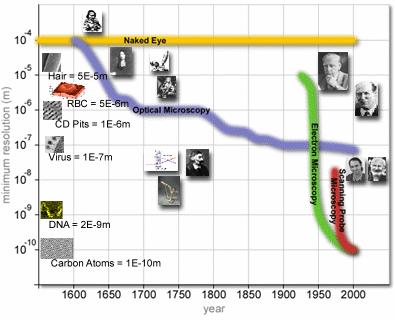
17 Optical Instrument Resolving Power RP in Angstroms Human eye 0.2 millimeters (mm) 2,000,000 A Light microscope 0.20 micrometers (µm) 2000 A Scanning electron microscope 5-10 nanometers (nm) A Transmission electron microscope 0.5 nanometers (nm) 5 A What are Electron Microscopes? They are microscopes that uses electrons instead of light to form an image and to examine objects on a very fine scale. What is a Scanning Electron Microscope? A microscope that uses electrons to examine the sample surface. This examination can yield the following information: -Topographical: surface features -Morphology: size and shape of surface features -Composition: elements and compounds and the relative amount of them. -Crystallographic: how the atoms are arranged in the sample.
18 Basic steps involved in all electron microscopes: o A beam of electrons is formed (electron gun) and accelerated toward the specimen using a positive electrical potential. o This beam is confined and focused using metal apertures and magnetic lenses into a thin, focused, monochromatic (all e-s have the same energy/wavelength) beam o This beam is focused onto the sample using a magnetic lens. o Interactions occur between the beam of electrons and the sample inside the interaction volume. othese interactions are detected and transformed into an image.
19 SEM High resolution (1-10nm in SE mode and nm in BSE mode). Bulk specimens Large depth of field. 3-D appearance Capable of low magnifications (complementary to optical microscopy) Advantages Better resolution and depth of field than optical microscopes Provides morphological and compositional information in small areas Semi or non destructive technique Relatively easy to use TEM High resolution (capable of atomic imaging Angstroms) Thin specimens Only 2-D appearance Provides crystallographic and structural information (visualization of defects, lattice arrangements, orientation relationships, etc.) SEM Disadvantages Specimen under vacuum (it must be stable under vacuum) Specimen must be conductive Specimen preparation can introduce artifacts Some visualization problems (up or down)
.")
20 Electron microscopes were developed due to the limitation of the light microscopes. The physics of light limits the magnifications to x500 x1000 and the resolution of 0.2μm. Additionally in light microscopy high magnifications are accompanied by very low depth of field, i.e. 2-D images (flat samples). Characteristic Information obtained from a SEM Topographic: Surface features of an object, how it looks. Morphological: The shape and size of the particles making up the object. Compositional: Elements and compounds that the object is made of. Crystallographic: How the atoms are arranged in 3-D.


21 The above information can be used to relate the properties of the materials with its microstructure. Example: Fracture mode Fracture along grain boundaries Fracture along pores The combination of large depth of field, higher magnification, greater resolution and compositional and crystallographic information makes the SEM one of the most heavily used instrument in research and semiconductor industry.
22 Basic Scanning Electron Microscope
23 oelectron Column: consists of an electron gun and two or more electron lenses, operating in a vacuum. oelectron Gun: produces a source of electrons and accelerates these electrons to an energy in the range 1-40 kev. oelectron lenses are used to reduce the diameter of this source of electrons and place a small, focused electron beam on the specimen and scan it. oworking Distance (W): The distance between the lower surface of the objective lens and the surface of the specimen is called working distance. odepth-of-focus: The capability of focusing features at different depth within the same image. osecondary Electron: are electrons of the specimen ejected during inelastic scattering of the energetic beam electrons. It is used to produce topographical images with a high depth of focus. obackscattering Detector: Collects the elastically scattered electrons and produces topographical and compositional images (contrast due to surface height changes and atomic number differences respectively). oeds and WDS Detector: Collects the x-ray radiation emitted from the specimen. It gives the chemical composition of the specimen. ovacuum System: produces a vacuum level acceptable for the operation of the electron gun and sample.


24 The image mode most commonly used is the secondary electron image. Changes in grey intensity over the screen suggest the presence of hills and valley on the surface sample and these changes do correspond to the topography of the surface. NaCl Crystals Red blood cells with white cell ~ 2-5 μm DNA ~2-1/2 nm diameter CD tracks 1mm thick Catalyst Particles Diamond Atomic Contrast
25 Types of Signals Detected in the Electron Microscope Signal Type Type of Signal Detected Image Information Image Resolution Secondary Secondary electrons Topography Voltage Contrast Magnetic and electric fields Backscattered Backscattered electrons Chemical Topographical Crystallographic 10nm 100nm 1μm 100nm Cathodo-luminescence Photons Chemical 100nm Absorption Absorbed Current Topography 1μm X-Rays Characteristic X-Rays Chemical 1μm Auger Auger emitted electrons Chemical 1μm Transmission Transmitted electrons Crystallographic Internal defects 1 10nm Conductive Current Sample Induced Current Induced current 100nm
MT Electron microscopy Scanning electron microscopy and electron probe microanalysis
 MT-0.6026 Electron microscopy Scanning electron microscopy and electron probe microanalysis Eero Haimi Research Manager Outline 1. Introduction Basics of scanning electron microscopy (SEM) and electron
Gaetano L Episcopo. Scanning Electron Microscopy Focus Ion Beam and. Pulsed Plasma Deposition
 Gaetano L Episcopo Scanning Electron Microscopy Focus Ion Beam and Pulsed Plasma Deposition Hystorical background Scientific discoveries 1897: J. Thomson discovers the electron. 1924: L. de Broglie propose
object objective lens eyepiece lens
 Advancing Physics G495 June 2015 SET #1 ANSWERS Field and Particle Pictures Seeing with electrons The compound optical microscope Q1. Before attempting this question it may be helpful to review ray diagram
Chapter 10: Wave Properties of Particles
 Chapter 10: Wave Properties of Particles Particles such as electrons may demonstrate wave properties under certain conditions. The electron microscope uses these properties to produce magnified images
Ecole Franco-Roumaine : Magnétisme des systèmes nanoscopiques et structures hybrides - Brasov, Modern Analytical Microscopic Tools
 1. Introduction Solid Surfaces Analysis Group, Institute of Physics, Chemnitz University of Technology, Germany 2. Limitations of Conventional Optical Microscopy 3. Electron Microscopies Transmission Electron
Why microscopy?
 Electron Microscopy Why microscopy? http://www.cellsalive.com/howbig.htm 2 Microscopes are used as magnifying tools (although not exclusively as will see later on). The resolution of the human eye is limited
High-Resolution. Transmission. Electron Microscopy
 Part 4 High-Resolution Transmission Electron Microscopy 186 Significance high-resolution transmission electron microscopy (HRTEM): resolve object details smaller than 1nm (10 9 m) image the interior of
AP5301/ Name the major parts of an optical microscope and state their functions.
 Review Problems on Optical Microscopy AP5301/8301-2015 1. Name the major parts of an optical microscope and state their functions. 2. Compare the focal lengths of two glass converging lenses, one with
Imaging Methods: Scanning Force Microscopy (SFM / AFM)
") Imaging Methods: Scanning Force Microscopy (SFM / AFM) The atomic force microscope (AFM) probes the surface of a sample with a sharp tip, a couple of microns long and often less than 100 Å in diameter.
Imaging Methods: Scanning Force Microscopy (SFM / AFM) The atomic force microscope (AFM) probes the surface of a sample with a sharp tip, a couple of microns long and often less than 100 Å in diameter.
h p λ = mν Back to de Broglie and the electron as a wave you will learn more about this Equation in CHEM* 2060
 Back to de Broglie and the electron as a wave λ = mν h = h p you will learn more about this Equation in CHEM* 2060 We will soon see that the energies (speed for now if you like) of the electrons in the
Electron Microprobe Analysis 1 Nilanjan Chatterjee, Ph.D. Principal Research Scientist
 12.141 Electron Microprobe Analysis 1 Nilanjan Chatterjee, Ph.D. Principal Research Scientist Massachusetts Institute of Technology Electron Microprobe Facility Department of Earth, Atmospheric and Planetary
Electron Microprobe Analysis 1 Nilanjan Chatterjee, Ph.D. Principal Research Scientist
 12.141 Electron Microprobe Analysis 1 Nilanjan Chatterjee, Ph.D. Principal Research Scientist Massachusetts Institute of Technology Electron Microprobe Facility Department of Earth, Atmospheric and Planetary
MSE 321 Structural Characterization
 Auger Spectroscopy Auger Electron Spectroscopy (AES) Scanning Auger Microscopy (SAM) Incident Electron Ejected Electron Auger Electron Initial State Intermediate State Final State Physical Electronics
= 6 (1/ nm) So what is probability of finding electron tunneled into a barrier 3 ev high?
 So what is probability of finding electron tunneled into a barrier 3 ev high?") STM STM With a scanning tunneling microscope, images of surfaces with atomic resolution can be readily obtained. An STM uses quantum tunneling of electrons to map the density of electrons on the surface
STM STM With a scanning tunneling microscope, images of surfaces with atomic resolution can be readily obtained. An STM uses quantum tunneling of electrons to map the density of electrons on the surface
CHARACTERIZATION of NANOMATERIALS KHP
 CHARACTERIZATION of NANOMATERIALS Overview of the most common nanocharacterization techniques MAIN CHARACTERIZATION TECHNIQUES: 1.Transmission Electron Microscope (TEM) 2. Scanning Electron Microscope
HOW TO APPROACH SCANNING ELECTRON MICROSCOPY AND ENERGY DISPERSIVE SPECTROSCOPY ANALYSIS. SCSAM Short Course Amir Avishai
 HOW TO APPROACH SCANNING ELECTRON MICROSCOPY AND ENERGY DISPERSIVE SPECTROSCOPY ANALYSIS SCSAM Short Course Amir Avishai RESEARCH QUESTIONS Sea Shell Cast Iron EDS+SE Fe Cr C Objective Ability to ask the
Auger Electron Spectroscopy Overview
 Auger Electron Spectroscopy Overview Also known as: AES, Auger, SAM 1 Auger Electron Spectroscopy E KLL = E K - E L - E L AES Spectra of Cu EdN(E)/dE Auger Electron E N(E) x 5 E KLL Cu MNN Cu LMM E f E
EDS User School. Principles of Electron Beam Microanalysis
 EDS User School Principles of Electron Beam Microanalysis Outline 1.) Beam-specimen interactions 2.) EDS spectra: Origin of Bremsstrahlung and characteristic peaks 3.) Moseley s law 4.) Characteristic
MSE 321 Structural Characterization
 Auger Spectroscopy Auger Electron Spectroscopy (AES) Scanning Auger Microscopy (SAM) Incident Electron Ejected Electron Auger Electron Initial State Intermediate State Final State Physical Electronics
Nanoelectronics 09. Atsufumi Hirohata Department of Electronics. Quick Review over the Last Lecture
 Nanoelectronics 09 Atsufumi Hirohata Department of Electronics 13:00 Monday, 12/February/2018 (P/T 006) Quick Review over the Last Lecture ( Field effect transistor (FET) ): ( Drain ) current increases
Massachusetts Institute of Technology. Dr. Nilanjan Chatterjee
 Massachusetts Institute of Technology Dr. Nilanjan Chatterjee Electron Probe Micro-Analysis (EPMA) Imaging and micrometer-scale chemical compositional analysis of solids Signals produced in The Electron
CBE Science of Engineering Materials. Scanning Electron Microscopy (SEM)
") CBE 30361 Science of Engineering Materials Scanning Electron Microscopy (SEM) Scale of Structure Organization Units: micrometer = 10-6 m = 1µm nanometer= 10-9 m = 1nm Angstrom = 10-10 m = 1Å A hair is
CBE 30361 Science of Engineering Materials Scanning Electron Microscopy (SEM) Scale of Structure Organization Units: micrometer = 10-6 m = 1µm nanometer= 10-9 m = 1nm Angstrom = 10-10 m = 1Å A hair is
Chapter 9. Electron mean free path Microscopy principles of SEM, TEM, LEEM
 Chapter 9 Electron mean free path Microscopy principles of SEM, TEM, LEEM 9.1 Electron Mean Free Path 9. Scanning Electron Microscopy (SEM) -SEM design; Secondary electron imaging; Backscattered electron
Part II: Thin Film Characterization
 Part II: Thin Film Characterization General details of thin film characterization instruments 1. Introduction to Thin Film Characterization Techniques 2. Structural characterization: SEM, TEM, AFM, STM
Analytical Methods for Materials
 Analytical Methods for Materials Lesson 21 Electron Microscopy and X-ray Spectroscopy Suggested Reading Leng, Chapter 3, pp. 83-126; Chapter 4, pp. 127-160; Chapter 6, pp. 191-219 P.J. Goodhew, J. Humphreys
Electron Microprobe Analysis and Scanning Electron Microscopy
 Electron Microprobe Analysis and Scanning Electron Microscopy Electron microprobe analysis (EMPA) Analytical technique in which a beam of electrons is focused on a sample surface, producing X-rays from
Chapter 37 Early Quantum Theory and Models of the Atom
 Chapter 37 Early Quantum Theory and Models of the Atom Units of Chapter 37 37-7 Wave Nature of Matter 37-8 Electron Microscopes 37-9 Early Models of the Atom 37-10 Atomic Spectra: Key to the Structure
Practical course in scanning electron microscopy
 Practical course in scanning electron microscopy Fortgeschrittenen Praktikum an der Technischen Universität München Wintersemester 2017/2018 Table of contents 1. Introduction 3 2. Formation of an electron
Scanning Electron Microscopy
 Scanning Electron Microscopy Amanpreet Kaur 1 www.reading.ac.uk/emlab Scanning Electron Microscopy What is scanning electron microscopy? Basic features of conventional SEM Limitations of conventional SEM
Surface Sensitivity & Surface Specificity
 Surface Sensitivity & Surface Specificity The problems of sensitivity and detection limits are common to all forms of spectroscopy. In its simplest form, the question of sensitivity boils down to whether
tip conducting surface
 PhysicsAndMathsTutor.com 1 1. The diagram shows the tip of a scanning tunnelling microscope (STM) above a conducting surface. The tip is at a potential of 1.0 V relative to the surface. If the tip is sufficiently
Lecture 5. X-ray Photoemission Spectroscopy (XPS)
") Lecture 5 X-ray Photoemission Spectroscopy (XPS) 5. Photoemission Spectroscopy (XPS) 5. Principles 5.2 Interpretation 5.3 Instrumentation 5.4 XPS vs UV Photoelectron Spectroscopy (UPS) 5.5 Auger Electron
Lecture 5 X-ray Photoemission Spectroscopy (XPS) 5. Photoemission Spectroscopy (XPS) 5. Principles 5.2 Interpretation 5.3 Instrumentation 5.4 XPS vs UV Photoelectron Spectroscopy (UPS) 5.5 Auger Electron
An Introduction to Diffraction and Scattering. School of Chemistry The University of Sydney
 An Introduction to Diffraction and Scattering Brendan J. Kennedy School of Chemistry The University of Sydney 1) Strong forces 2) Weak forces Types of Forces 3) Electromagnetic forces 4) Gravity Types
Chemical Analysis in TEM: XEDS, EELS and EFTEM. HRTEM PhD course Lecture 5
 Chemical Analysis in TEM: XEDS, EELS and EFTEM HRTEM PhD course Lecture 5 1 Part IV Subject Chapter Prio x-ray spectrometry 32 1 Spectra and mapping 33 2 Qualitative XEDS 34 1 Quantitative XEDS 35.1-35.4
SCANNING ELECTRON MICROSCOPE
 21.05.2010 Hacettepe University SCANNING ELECTRON MICROSCOPE Berrak BOYBEK Tuğba ÖZTÜRK Vicdan PINARBAŞI Cahit YAYAN OUTLINE Definition of scanning electron microscope History Applications of SEM Components
MT Electron microscopy Scanning electron microscopy and electron probe microanalysis
 MT-0.6026 Electron microscopy Scanning electron microscopy and electron probe microanalysis Eero Haimi Research Manager Outline 1. Introduction Basics of scanning electron microscopy (SEM) and electron
Chapter 12. Nanometrology. Oxford University Press All rights reserved.
 Chapter 12 Nanometrology Introduction Nanometrology is the science of measurement at the nanoscale level. Figure illustrates where nanoscale stands in relation to a meter and sub divisions of meter. Nanometrology
Secondary Ion Mass Spectrometry (SIMS)
") CHEM53200: Lecture 10 Secondary Ion Mass Spectrometry (SIMS) Major reference: Surface Analysis Edited by J. C. Vickerman (1997). 1 Primary particles may be: Secondary particles can be e s, neutral species
CHEM53200: Lecture 10 Secondary Ion Mass Spectrometry (SIMS) Major reference: Surface Analysis Edited by J. C. Vickerman (1997). 1 Primary particles may be: Secondary particles can be e s, neutral species
ABC s of Electrochemistry series Materials Characterization techniques: SEM and EDS Ana María Valenzuela-Muñiz November 3, 2011
 ABC s of Electrochemistry series Materials Characterization techniques: SEM and EDS Ana María Valenzuela-Muñiz November 3, 2011 CEER, Department of Chemical and Biomolecular Engineering Outline Introduction
MS482 Materials Characterization ( 재료분석 ) Lecture Note 4: XRF
 Lecture Note 4: XRF") 2016 Fall Semester MS482 Materials Characterization ( 재료분석 ) Lecture Note 4: XRF Byungha Shin Dept. of MSE, KAIST 1 Course Information Syllabus 1. Overview of various characterization techniques (1 lecture)
2016 Fall Semester MS482 Materials Characterization ( 재료분석 ) Lecture Note 4: XRF Byungha Shin Dept. of MSE, KAIST 1 Course Information Syllabus 1. Overview of various characterization techniques (1 lecture)
Modern Optical Spectroscopy
 Modern Optical Spectroscopy X-Ray Microanalysis Shu-Ping Lin, Ph.D. Institute of Biomedical Engineering E-mail: splin@dragon.nchu.edu.tw Website: http://web.nchu.edu.tw/pweb/users/splin/ Backscattered
MEMS Metrology. Prof. Tianhong Cui ME 8254
 MEMS Metrology Prof. Tianhong Cui ME 8254 What is metrology? Metrology It is the science of weights and measures Refers primarily to the measurements of length, weight, time, etc. Mensuration- A branch
Scanning Electron Microscopy
 Scanning Electron Microscopy Field emitting tip Grid 2kV 100kV Anode ZEISS SUPRA Variable Pressure FESEM Dr Heath Bagshaw CMA bagshawh@tcd.ie Why use an SEM? Fig 1. Examples of features resolvable using
PHYS-E0541:Special Course in Physics Gas phase synthesis of carbon nanotubes for thin film application. Electron Microscopy. for
 PHYS-E0541:Special Course in Physics Gas phase synthesis of carbon nanotubes for thin film application Electron Microscopy for Introduction to Electron Microscopy Carbon Nanomaterials (nanotubes) Dr. Hua
SEM stands for Scanning Electron Microscopy. The earliest known work describing
 1. HISTORY ABOUT SEM SEM stands for Scanning Electron Microscopy. The earliest known work describing the concept of a Scanning Electron Microscope was by M. Knoll (1935) who, along with other pioneers
Basic structure of SEM
 Table of contents Basis structure of SEM SEM imaging modes Comparison of ordinary SEM and FESEM Electron behavior Electron matter interaction o Elastic interaction o Inelastic interaction o Interaction
M2 TP. Low-Energy Electron Diffraction (LEED)
") M2 TP Low-Energy Electron Diffraction (LEED) Guide for report preparation I. Introduction: Elastic scattering or diffraction of electrons is the standard technique in surface science for obtaining structural
M2 TP Low-Energy Electron Diffraction (LEED) Guide for report preparation I. Introduction: Elastic scattering or diffraction of electrons is the standard technique in surface science for obtaining structural
Transmission Electron Microscopy
 L. Reimer H. Kohl Transmission Electron Microscopy Physics of Image Formation Fifth Edition el Springer Contents 1 Introduction... 1 1.1 Transmission Electron Microscopy... 1 1.1.1 Conventional Transmission
Electron Microscopy I
 Characterization of Catalysts and Surfaces Characterization Techniques in Heterogeneous Catalysis Electron Microscopy I Introduction Properties of electrons Electron-matter interactions and their applications
Nano-Microscopy. Lecture 2. Scanning and Transmission Electron Microscopies: Principles. Pavel Zinin HIGP, University of Hawaii, Honolulu, USA
 GG 711: Advanced Techniques in Geophysics and Materials Science Nano-Microscopy. Lecture 2 Scanning and Transmission Electron Microscopies: Principles Pavel Zinin HIGP, University of Hawaii, Honolulu,
Lecture 5: Characterization methods
 Lecture 5: Characterization methods X-Ray techniques Single crystal X-Ray Diffration (XRD) Powder XRD Thin film X-Ray Reflection (XRR) Microscopic methods Optical microscopy Electron microscopies (SEM,
EE 527 MICROFABRICATION. Lecture 5 Tai-Chang Chen University of Washington
 EE 527 MICROFABRICATION Lecture 5 Tai-Chang Chen University of Washington MICROSCOPY AND VISUALIZATION Electron microscope, transmission electron microscope Resolution: atomic imaging Use: lattice spacing.
Structure analysis: Electron diffraction LEED TEM RHEED
 Structure analysis: Electron diffraction LEED: Low Energy Electron Diffraction SPA-LEED: Spot Profile Analysis Low Energy Electron diffraction RHEED: Reflection High Energy Electron Diffraction TEM: Transmission
QUANTUM PHYSICS. Limitation: This law holds well only for the short wavelength and not for the longer wavelength. Raleigh Jean s Law:
 Black body: A perfect black body is one which absorbs all the radiation of heat falling on it and emits all the radiation when heated in an isothermal enclosure. The heat radiation emitted by the black
Lecture 2: Quantum Mechanics and Relativity
 Lecture 2: Quantum Mechanics and Relativity Atom Atomic number A Number of protons Z Number of neutrons A-Z Number of electrons Z Charge of electron = charge of proton ~1.6 10-19 C Size of the atom ~10-10
CHEM 681 Seminar Mingqi Zhao April 20, 1998 Room 2104, 4:00 p.m. High Resolution Transmission Electron Microscopy: theories and applications
 CHEM 681 Seminar Mingqi Zhao April 20, 1998 Room 2104, 4:00 p.m. High Resolution Transmission Electron Microscopy: theories and applications In materials science, people are always interested in viewing
April 10th-12th, 2017
 Thomas LaGrange, Ph.D. Faculty Lecturer and Senior Staff Scientist Introduction: Basics of Transmission Electron Microscopy (TEM) TEM Doctoral Course MS-637 April 10th-12th, 2017 Outline 1. What is microcopy?
MICRO-TOMOGRAPHY AND X-RAY ANALYSIS OF GEOLOGICAL SAMPLES
 THE PUBLISHING HOUSE PROCEEDINGS OF THE ROMANIAN ACADEMY, Series A, OF THE ROMANIAN ACADEMY Volume 18, Number 1/2017, pp. 42 49 MICRO-TOMOGRAPHY AND X-RAY ANALYSIS OF GEOLOGICAL SAMPLES Ion GRUIA University
1) Introduction 2) Photo electric effect 3) Dual nature of matter 4) Bohr s atom model 5) LASERS
 Introduction 2) Photo electric effect 3) Dual nature of matter 4) Bohr s atom model 5) LASERS") 1) Introduction 2) Photo electric effect 3) Dual nature of matter 4) Bohr s atom model 5) LASERS 1. Introduction Types of electron emission, Dunnington s method, different types of spectra, Fraunhoffer
1) Introduction 2) Photo electric effect 3) Dual nature of matter 4) Bohr s atom model 5) LASERS 1. Introduction Types of electron emission, Dunnington s method, different types of spectra, Fraunhoffer
WAVES AND PARTICLES. (c)
") WAVES AND PARTICLES 1. An electron and a proton are accelerated through the same potential difference. The ration of their De Broglie wave length will be -- (a) (b) (c) (d) 1 2. What potential must be
WAVES AND PARTICLES 1. An electron and a proton are accelerated through the same potential difference. The ration of their De Broglie wave length will be -- (a) (b) (c) (d) 1 2. What potential must be
Auger Electron Spectroscopy
 Auger Electron Spectroscopy Auger Electron Spectroscopy is an analytical technique that provides compositional information on the top few monolayers of material. Detect all elements above He Detection
Lecture 22 Ion Beam Techniques
 Lecture 22 Ion Beam Techniques Schroder: Chapter 11.3 1/44 Announcements Homework 6/6: Will be online on later today. Due Wednesday June 6th at 10:00am. I will return it at the final exam (14 th June).
stands for Transmission Electron (Microscope/Microscopy) Q: Why use electrons instead of light for imaging nanomaterials?
 Q: Why use electrons instead of light for imaging nanomaterials?") What is TEM? stands for Transmission Electron (Microscope/Microscopy) Q: Why use electrons instead of light for imaging nanomaterials? A: 1) Shorter wavelength () Higher resolution ) Wavelength determined
What is TEM? stands for Transmission Electron (Microscope/Microscopy) Q: Why use electrons instead of light for imaging nanomaterials? A: 1) Shorter wavelength () Higher resolution ) Wavelength determined
Everhart-Thornley detector
 SEI Detector Everhart-Thornley detector Microscope chamber wall Faraday cage Scintillator Electrons in Light pipe Photomultiplier Electrical signal out Screen Quartz window +200 V +10 kv Always contains
Chapter 10. Nanometrology. Oxford University Press All rights reserved.
 Chapter 10 Nanometrology Oxford University Press 2013. All rights reserved. 1 Introduction Nanometrology is the science of measurement at the nanoscale level. Figure illustrates where nanoscale stands
(i.e. what you should be able to answer at end of lecture)
") Today s Announcements 1. Test given back next Wednesday 2. HW assigned next Wednesday. 3. Next Monday 1 st discussion about Individual Projects. Today s take-home lessons (i.e. what you should be able
Today s Announcements 1. Test given back next Wednesday 2. HW assigned next Wednesday. 3. Next Monday 1 st discussion about Individual Projects. Today s take-home lessons (i.e. what you should be able
Second Edition. John J. Friel
 Second Edition John J. Friel Library of Congress Cataloging-in-Publication Data X-ray and image analysis in electron microscopy/ John J. Friel. 98 p. 22 cm. Includes bibliographical references and index.
6. Analytical Electron Microscopy
 Physical Principles of Electron Microscopy 6. Analytical Electron Microscopy Ray Egerton University of Alberta and National Institute of Nanotechnology Edmonton, Canada www.tem-eels.ca regerton@ualberta.ca
Chapter 37 Early Quantum Theory and Models of the Atom. Copyright 2009 Pearson Education, Inc.
 Chapter 37 Early Quantum Theory and Models of the Atom Planck s Quantum Hypothesis; Blackbody Radiation Photon Theory of Light and the Photoelectric Effect Energy, Mass, and Momentum of a Photon Compton
MS482 Materials Characterization ( 재료분석 ) Lecture Note 5: RBS
 Lecture Note 5: RBS") 2016 Fall Semester MS482 Materials Characterization ( 재료분석 ) Lecture Note 5: RBS Byungha Shin Dept. of MSE, KAIST 1 Course Information Syllabus 1. Overview of various characterization techniques (1 lecture)
2016 Fall Semester MS482 Materials Characterization ( 재료분석 ) Lecture Note 5: RBS Byungha Shin Dept. of MSE, KAIST 1 Course Information Syllabus 1. Overview of various characterization techniques (1 lecture)
Methods of surface analysis
 Methods of surface analysis Nanomaterials characterisation I RNDr. Věra Vodičková, PhD. Surface of solid matter: last monoatomic layer + absorbed monolayer physical properties are effected (crystal lattice
Spectroscopy on Mars!
 Spectroscopy on Mars! Pathfinder Spirit and Opportunity Real World Friday H2A The Mars Pathfinder: Geological Elemental Analysis On December 4th, 1996, the Mars Pathfinder was launched from earth to begin
Lecture 20 Optical Characterization 2
 Lecture 20 Optical Characterization 2 Schroder: Chapters 2, 7, 10 1/68 Announcements Homework 5/6: Is online now. Due Wednesday May 30th at 10:00am. I will return it the following Wednesday (6 th June).
MSE 321 Structural Characterization
 Optical Microscope Plan Lenses In an "ideal" single-element lens system all planar wave fronts are focused to a point at distance f from the lens; therefore: Image near the optical axis will be in perfect
Invited Lecture. "Different Aspects of Electron Microscopy. Sardar Vallabhbhai National Institute of Technology, Surat. Deepak Rajput & S.K.
 Invited Lecture on "Different Aspects of Electron Microscopy at Sardar Vallabhbhai National Institute of Technology, Surat Deepak Rajput & S.K. Tiwary R&D and Product Development Essar Steel Limited Abstract
KMÜ 396 MATERIALS SCIENCE AND TECH. I PRESENTATION ELECTRON ENERGY LOSS SPECTROSCOPY (EELS) TUĞÇE SEZGİN
 TUĞÇE SEZGİN") KMÜ 396 MATERIALS SCIENCE AND TECH. I PRESENTATION ELECTRON ENERGY LOSS SPECTROSCOPY (EELS) TUĞÇE SEZGİN 20970725 HACETTEPE UNIVERSITY DEPARTMENT OF CHEMICAL ENGINEERING, SPRING 2011,APRIL,ANKARA CONTENTS
KMÜ 396 MATERIALS SCIENCE AND TECH. I PRESENTATION ELECTRON ENERGY LOSS SPECTROSCOPY (EELS) TUĞÇE SEZGİN 20970725 HACETTEPE UNIVERSITY DEPARTMENT OF CHEMICAL ENGINEERING, SPRING 2011,APRIL,ANKARA CONTENTS
Chapter 27 Early Quantum Theory and Models of the Atom Discovery and Properties of the electron
 Chapter 27 Early Quantum Theory and Models of the Atom 27-1 Discovery and Properties of the electron Measure charge to mass ratio e/m (J. J. Thomson, 1897) When apply magnetic field only, the rays are
Characterisation of Catalysts Using Secondary and Backscattered Electron In-lens Detectors
 Platinum Metals Rev., 2014, 58, (2), 106 110 FINAL ANALYSIS Characterisation of Catalysts Using Secondary and Backscattered Electron In-lens Detectors Heterogeneous catalysis often involves the use of
4. Inelastic Scattering
 1 4. Inelastic Scattering Some inelastic scattering processes A vast range of inelastic scattering processes can occur during illumination of a specimen with a highenergy electron beam. In principle, many
Module 02: Wave-particle duality, de Broglie waves and the Uncertainty principle
 PG Pathshala Subject: BIOPHYSICS Paper 0: Quantum Biophysics Module 0: Wave-particle duality, de Broglie waves and the Uncertainty principle Principal Investigator: Prof. Moganty R. Rajeswari Professor,
DUAL NATURE OF RADIATION AND MATTER
 Chapter Eleven DUAL NATURE OF RADIATION AND MATTER MCQ I 111 A particle is dropped from a height H The de Broglie wavelength of the particle as a function of height is proportional to (a) H (b) H 1/2 (c)
Electron probe microanalysis - Electron microprobe analysis EPMA (EMPA) What s EPMA all about? What can you learn?
 What s EPMA all about? What can you learn?") Electron probe microanalysis - Electron microprobe analysis EPMA (EMPA) What s EPMA all about? What can you learn? EPMA - what is it? Precise and accurate quantitative chemical analyses of micron-size
Electron probe microanalysis - Electron microprobe analysis EPMA (EMPA) What s EPMA all about? What can you learn? EPMA - what is it? Precise and accurate quantitative chemical analyses of micron-size
Electron and electromagnetic radiation
 Electron and electromagnetic radiation Generation and interactions with matter Stimuli Interaction with sample Response Stimuli Waves and energy The energy is propotional to 1/λ and 1/λ 2 λ λ 1 Electromagnetic
 UNIT VII DUAL NATURE OF MATTER AND RADIATIONS (4marks) VERY SHORT ANSWER TYPE QUESTIONS:- 1. An electron and photon have same wavelength. Which one of the two has more energy? Relativistic energy of a
Physics 100 PIXE F06
 Introduction: Ion Target Interaction Elastic Atomic Collisions Very low energies, typically below a few kev Surface composition and structure Ion Scattering spectrometry (ISS) Inelastic Atomic Collisions
Conventional Transmission Electron Microscopy. Introduction. Text Books. Text Books. EMSE-509 CWRU Frank Ernst
 Text Books Conventional Transmission Electron Microscopy EMSE-509 CWRU Frank Ernst D. B. Williams and C. B. Carter: Transmission Electron Microscopy, New York: Plenum Press (1996). L. Reimer: Transmission
Particles and Waves Particles Waves
 Particles and Waves Particles Discrete and occupy space Exist in only one location at a time Position and velocity can be determined with infinite accuracy Interact by collisions, scattering. Waves Extended,
INDIAN INSTITUTE OF TECHNOLOGY ROORKEE NPTEL NPTEL ONLINE CERTIFICATION COURSE. Biomedical Nanotechnology. Lec-05 Characterisation of Nanoparticles
 INDIAN INSTITUTE OF TECHNOLOGY ROORKEE NPTEL NPTEL ONLINE CERTIFICATION COURSE Biomedical Nanotechnology Lec-05 Characterisation of Nanoparticles Dr. P. Gopinath Department of Biotechnology Indian Institute
The Basic of Transmission Electron Microscope. Text book: Transmission electron microscopy by David B Williams & C. Barry Carter.
 The Basic of Transmission Electron Microscope Text book: Transmission electron microscopy by David B Williams & C. Barry Carter. 2009, Springer Background survey http://presemo.aalto.fi/tem1 Microscopy
Chap. 3. Elementary Quantum Physics
 Chap. 3. Elementary Quantum Physics 3.1 Photons - Light: e.m "waves" - interference, diffraction, refraction, reflection with y E y Velocity = c Direction of Propagation z B z Fig. 3.1: The classical view
ECE Semiconductor Device and Material Characterization
 ECE 4813 Semiconductor Device and Material Characterization Dr. Alan Doolittle School of Electrical and Computer Engineering Georgia Institute of Technology As with all of these lecture slides, I am indebted
A) n L < 1.0 B) n L > 1.1 C) n L > 1.3 D) n L < 1.1 E) n L < 1.3
 n L < 1.0 B) n L > 1.1 C) n L > 1.3 D) n L < 1.1 E) n L < 1.3") 1. A beam of light passes from air into water. Which is necessarily true? A) The frequency is unchanged and the wavelength increases. B) The frequency is unchanged and the wavelength decreases. C) The
1. A beam of light passes from air into water. Which is necessarily true? A) The frequency is unchanged and the wavelength increases. B) The frequency is unchanged and the wavelength decreases. C) The
Exercise 1 Atomic line spectra 1/9
 Exercise 1 Atomic line spectra 1/9 The energy-level scheme for the hypothetical one-electron element Juliettium is shown in the figure on the left. The potential energy is taken to be zero for an electron
MS482 Materials Characterization ( 재료분석 ) Lecture Note 2: UPS
 Lecture Note 2: UPS") 2016 Fall Semester MS482 Materials Characterization ( 재료분석 ) Lecture Note 2: UPS Byungha Shin Dept. of MSE, KAIST 1 Course Information Syllabus 1. Overview of various characterization techniques (1 lecture)
2016 Fall Semester MS482 Materials Characterization ( 재료분석 ) Lecture Note 2: UPS Byungha Shin Dept. of MSE, KAIST 1 Course Information Syllabus 1. Overview of various characterization techniques (1 lecture)
Energy-Filtering. Transmission. Electron Microscopy
 Part 3 Energy-Filtering Transmission Electron Microscopy 92 Energy-Filtering TEM Principle of EFTEM expose specimen to mono-energetic electron radiation inelastic scattering in the specimen poly-energetic
Weak-Beam Dark-Field Technique
 Basic Idea recall bright-field contrast of dislocations: specimen close to Bragg condition, s î 0 Weak-Beam Dark-Field Technique near the dislocation core, some planes curved to s = 0 ) strong Bragg reflection
Supporting Information s for
 Supporting Information s for # Self-assembling of DNA-templated Au Nanoparticles into Nanowires and their enhanced SERS and Catalytic Applications Subrata Kundu* and M. Jayachandran Electrochemical Materials
Lecture PowerPoints. Chapter 27 Physics: Principles with Applications, 7th edition Giancoli
 Lecture PowerPoints Chapter 27 Physics: Principles with Applications, 7th edition Giancoli This work is protected by United States copyright laws and is provided solely for the use of instructors in teaching
Film Characterization Tutorial G.J. Mankey, 01/23/04. Center for Materials for Information Technology an NSF Materials Science and Engineering Center
 Film Characterization Tutorial G.J. Mankey, 01/23/04 Theory vs. Experiment A theory is something nobody believes, except the person who made it. An experiment is something everybody believes, except the
SOLID STATE PHYSICS PHY F341. Dr. Manjuladevi.V Associate Professor Department of Physics BITS Pilani
 SOLID STATE PHYSICS PHY F341 Dr. Manjuladevi.V Associate Professor Department of Physics BITS Pilani 333031 manjula@bits-pilani.ac.in Characterization techniques SEM AFM STM BAM Outline What can we use