ELCT201: DIGITAL LOGIC DESIGN
|
|
|
- Hector Butler
- 6 years ago
- Views:
Transcription

1 ELCT2: DIGITL LOGIC DESIGN Dr. Eng. Haitham Omran, Dr. Eng. Wassim lexan, Lecture Following the slides of Dr. hmed H. Madian ذو الحجة 438 ه Winter 27
2 2
3 3
4 4


5 WHT IS THE IMPORTNCE OF DIGITL LOGIC? Most of electronic devices consist of two integrated systems Hardware Circuits that execute the program commands To learn more about how to design this you need to study Digital Logic Design Software Programs that control hardware to execute user wishes To learn how to design this you need to study Computer Science 5

6 THE IMPORTNCE OF DIGITL LOGIC Floyd th edition 6
7 COURSE OBJECTIVES Why Digital Logic Design? Understand the theory of operation for most of digital electronic devices, nalyze how a digital computer performs complex operations, based on simply manipulating bits (zeros and ones), Design digital logic systems! 7
8 TEXT ND REFERENCE BOOKS Textbook: M. Morris Mano, Digital Design, 3 rd Edition, Prentice-Hall, 22, ISBN References: S. Brown, Z. Vranesic, Fundamentals Of Digital Logic With Vhdl Design, ISBN G. Langholz,. Kandel, & J. L Mott, Foundations of digital logic design, ISBN D. J. Comer, Digital Logic and State Machine Design, ISBN Thomas L. Floyd, Digital Fundamentals, ISBN
9 ELCT 2: DIGITL LOGIC Instructors Dr. Eng. Haitham Omran Dr. Eng. Wassim lexan Teaching assistants Eng. Fadwa Foda Eng. Sarah zzam Eng. Engy Maher Eng. Youstina Megalli Eng. li hmed Eng. banoub Mamdouh Eng. Mostafa El-Swefy Eng. Yasmine Hossam Grading ssignments % Quizzes 2% Midterm Exam 25% Final Exam 45% 9
10 COURSE OUTLINE. Introduction 2. Gate-Level Minimization 3. Combinational Logic 4. Synchronous Sequential Logic 5. Registers and Counters 6. Memories and Programmable Logic

11 FLSHBCK ON DIGITL LOGIC DESIGN HISTORY

12 HOW DID IT LL STRT? 85: George Boole invents Boolean algebra 2

13 HOW DID IT LL STRT? 946: ENIC, the first electronic computer is developed 8, vacuum tubes 5, operations per second, square feet It really cost a lot of power to turn on the switch! 3

14 Dr. Haitham Omran, Dr. Wassim lexan 4

15 ND IT WENT ON 947: Shockley, Brattain, and Bardeen invent the transistor Replaces vacuum tubes Enables integration of multiple devices into one package 956: They received the Nobel Prize in Physics 5
")
 Transistor, resistors and capacitors on the same")

16 ND IT WENT ON 955: TRDIC: T&T Bell Labs announced the first fully transistorized computer 958: The st (2D) Integrated Circuit (Kilby received the Nobel prize in 2) Transistor, resistors and capacitors on the same piece of semiconductor Interconnects between components is not integrated Low connectivity between components 6


17 ND IT WENT ON 97: Intel s 44 st microprocessor Maximum clock rate is 74 khz 463 to 926 instructions per second Now: Intel Core i7-67k Processor (8M Cache, up to 4.2 GHz) 7


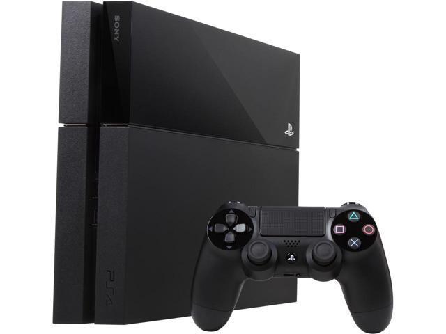
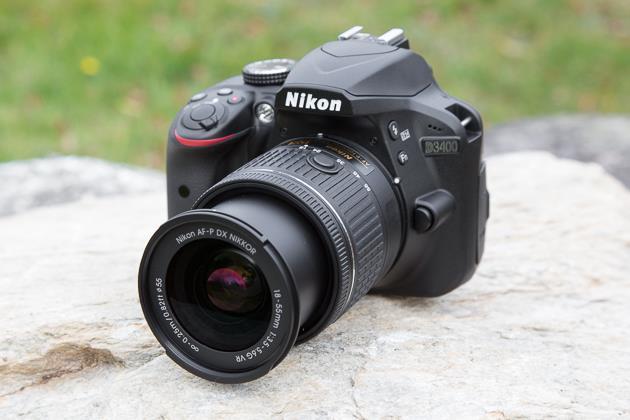
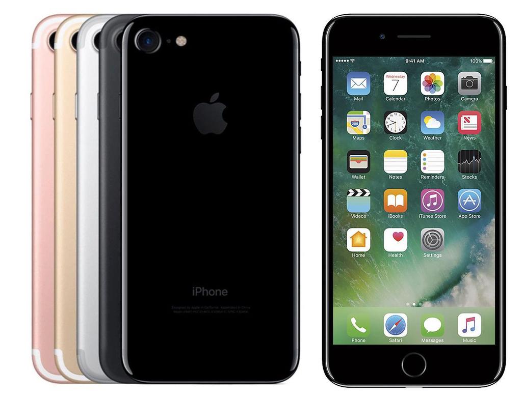
18 PPLICTIONS OF DIGITL LOGIC DESIGN Conventional computer design CPUs, busses, peripherals Networking and communications Phones, modems, routers Embedded products Cars Toys ppliances Entertainment devices: MP3 players, gaming consoles (PlayStation, Xbox, etc ) 8
19 BUT WHT IS THE MENING OF DIGITL LOGIC DESIGN? 9
20 WHT IS DIGITL? Digital describes any system based on discontinuous data or events. Computers are digital machines because at their most basic level they can distinguish between just two values, and, or off and on. There is no simple way to represent all the values in between, such as.25. ll data that a computer processes must be encoded digitally, as a series of zeroes and ones. 2


21 NLOG VS. DIGITL n analog signal is any variable signal continuous in both time and amplitude. e.g. Sound Example: typical analog device is a clock in which the hands move continuously around the face. Such a clock is capable of indicating every possible time of day. In contrast, a digital clock is capable of representing only a finite number of times (every tenth of a second, for example). 2

22 WHY DIGITL? Digital systems are easier to design and implement than analog systems. 22
23 WHT IS LOGIC DESIGN? Given a specification of a problem, come up with a way of solving it choosing appropriately from a collection of available components, while meeting some criteria for size, cost, power, etc 23

24 WHT RE THE BSIC UNITS USED TO BUILD THESE DIGITL CIRCUITS? Digital Logic Gates! Digital Logic Gates are the basic unit to build any digital circuit 24

25 DIGITL LOGIC GTES B Digital System Digital logic circuits are hardware components that manipulate binary information (we call them gates) digital system is basically a black box with a minimum of one input and one output Inside this box, are millions of switches called transistors Transistors perform different functions according to inputs In binary logic circuits there are only two levels: and 25
26 Digital Logic levels What is the physical meaning of logic and logic? How can we recognize them? 26
27 DIGITL LOGIC LEVELS (CONT.) Electrical Signals [ voltages or currents ] that exist throughout a digital system are in either of two recognizable values [ logic or logic ] Voltage Intermediate region, crossed only during state transition Logic range Logic range Transition, occurs between the two limits time 27
28 Boolean lgebra What is the difference between the Boolean algebra and arithmetic algebra? The First obvious difference is that in Boolean algebra we have only (+) and () operators we do not have subtraction (-) or division (/) like in math 28
29 BINRY LOGIC You should distinguish between binary logic and binary arithmetic. rithmetic variables are numbers that consist of many digits. Carry Two digits rithmetic + = binary logic variable is always either or. Binary + = 29
.")
30 DIGITL LOGIC GTES There are three fundamental logical operations, from which all other functions, no matter how complex, can be derived. These Basic functions are named: ND, OR, NOT (INVERTER). Each of these has a specific symbol and a clearly-defined behavior 3
31 BSIC DIGITL LOGIC GTES (CONT.) ND Gate Represented by any of the following notations: X ND Y X. Y X Y Function definition: Z= only if X=Y= otherwise X Y ND ND Symbol diagram X Y Z Switch representation 3
32 BSIC DIGITL LOGIC GTES (CONT.) OR Gate Represented by any of the following notations: X OR Y X + Y X v Y X Y OR Symbol diagram X Z Function definition: OR Z = if X= or Y = or both X=Y= if X=Y= Y Switch representation 32
33 BSIC DIGITL LOGIC GTES (CONT.) NOT (Inverter) Gate Represented by a bar over the variable X NOT Z Function definition: X Z is what X is not It is also called complement operation, as it changes s to s and s to s. Symbol diagram X NOT z Switch representation 33
34 LOGIC GTES TIMING DIGRM Timing diagrams illustrate the response of any gate to all possible input signal combinations. The horizontal axis of the timing diagram represents time and the vertical axis represents the signal as it changes between the two possible voltage levels or 34
35 DIGITL LOGIC GTES (CONT.) Gates can have more than 2 inputs Other Types of logic gates 35
36 HOW TO DESCRIBE LOGIC SYSTEM? By using one of the following two methods: Truth Table Boolean Expression 36
37 TRUTH TBLE Truth Table is a table of combinations of the binary variables showing the relationship between the different values that the input variables take and the result of the operation (output). n The number of rows in the Truth Table is 2, where n = number of input variables in the function. The binary combinations are obtained from the binary number by counting from to 2 n Example: ND gate with 2 inputs n=2 The truth table has 2 2 rows = 4 The binary combinations is from to (2 2 -=(3)) [,,,] X Y ll input combinations Z X Y Truth table of an ND gate Z 37 output
38 BOOLEN EXPRESSIONS We can use these basic operations to form more complex expressions: f(x,y,z) = (x + y )z + x Some terminology and notation: f is the name of the function. (x,y,z) are the input variables, each representing or. Listing the inputs is optional, but sometimes helpful. literal is any occurrence of an input variable or its complement. The function above has four literals: x, y, z, and x. Precedences are important, but not too difficult. NOT has the highest precedence, followed by ND, and then OR. Fully parenthesized, the function above would be kind of messy: f(x,y,z) = (((x +(y ))z) + x ) 38 38
39 How to get the Boolean Expression from the truth table? 39
40 BOOLEN EXPRESSIONS FROM TRUTH TBLES Each in the output of a truth table specifies one term in the corresponding boolean expression. The expression can be read off by inspection B C F Sum-of-Products-lgorithm F is true when: OR is false ND B is true ND C is false is true ND B is true ND C is true F = BC + BC 4
41 NOTHER EXMPLE B C F F =? F = B C + BC + B C + BC 4
42 BSIC LOGIC GTES We have defined three basic logic gates and operators lso, we could build any digital circuit from those basic logic gates. In digital Logic, we are not using normal mathematics we are using Boolean algebra So, we need to know the laws & rules of Boolean lgebra 42
43 LWS & RULES OF BOOLEN LGEBR The basic laws of Boolean algebra The commutative law The associative law The distributive law 43
44 COMMUTTIVE LW The commutative law of addition for two variables is written as: +B = B+ B +B B B+ The commutative law of multiplication for two variables is written as: B = B B B B B 44
45 SSOCITIVE LW The associative law of addition for 3 variables is written as: +(B+C) = (+B)+C B C B+C +(B+C) B C +B (+B)+C The associative law of multiplication for 3 variables is written as: (BC) = (B)C B C BC (BC) B C B (B)C 45
46 DISTRIBUTIVE LW The distributive law for multiplication as follows: (B+C) = B + C B B+C C X X=(B+C) B B C C The distributive law for addition is as follows +(B.C) = (+B)(+C) B BC C X X=+(B.C) B C X=B+C +B X +C X=(+B)(+C) 46 X
47 BSIC THEOREMS OF BOOLEN LGEBR ( B B B)( B C) BC, B, and C can represent a single variable or a combination of variables. 47
 Interchange ND () with OR (+) (and Vice-versa) X X Duality X X X XY X X XY X X(X Y) X Duality X(X Y) X X X X Duality XX X")
48 DULITY PRINCIPLE Boolean equation remains valid if we take the dual of the expressions on both sides of the equals sign Dual of expression it means, Interchange s with s (and Vice-versa) Interchange ND () with OR (+) (and Vice-versa) X X Duality X X X XY X X XY X X(X Y) X Duality X(X Y) X X X X Duality XX X Duality 48
49 DEMORGN S LW B B B B 49
50 EXMPLE Get the logic function from the following truth table and implement it using basic logic gates (ND, OR, NOT) B P Can we make this circuit better? Cheaper: fewer gates Faster: fewer delays from inputs to outputs P = B + B + B It needs two inverters + three ND + two OR gates = 7 gates to implement the function The answer in the simplification of the logic function 5
51 SIMPLIFICTION OF THE LOGIC FUNCTION B + B + B = * (B + B) + * B (Distributivity) = * (B + B ) + * B (Commutativity) = * + * B (x + x = ) = + ( * B ) (x +x y)=(x+x )(x+y)(distributivity) = ( + B ) (De Morgan s) = ( B) GTE (NND) ONLY From 7 gates using simplification rules could be optimized to one gate 5
52 52 Z Y X Z Y X Z Y X Z Y X DERIVED GTES NND ND-Invert NOR OR-Invert XOR Odd XNOR Even
53 FINL NOTE Check the website for the course materials as well as any announcements 53
ELCT201: DIGITAL LOGIC DESIGN
 ELCT2: DIGITAL LOGIC DESIGN Dr. Eng. Haitham Omran, haitham.omran@guc.edu.eg Dr. Eng. Wassim Alexan, wassim.joseph@guc.edu.eg Lecture 2 Following the slides of Dr. Ahmed H. Madian ذو الحجة 438 ه Winter
Boolean Algebra & Logic Gates. By : Ali Mustafa
 Boolean Algebra & Logic Gates By : Ali Mustafa Digital Logic Gates There are three fundamental logical operations, from which all other functions, no matter how complex, can be derived. These Basic functions
ELCT201: DIGITAL LOGIC DESIGN
 ELCT2: DIGITAL LOGIC DESIGN Dr. Eng. Haitham Omran, haitham.omran@guc.edu.eg Dr. Eng. Wassim Alexan, wassim.joseph@guc.edu.eg Lecture 4 Following the slides of Dr. Ahmed H. Madian محرم 439 ه Winter 28
ELCT201: DIGITAL LOGIC DESIGN
 ELCT201: DIGITAL LOGIC DESIGN Dr. Eng. Haitham Omran, haitham.omran@guc.edu.eg Dr. Eng. Wassim Alexan, wassim.joseph@guc.edu.eg Lecture 5 Following the slides of Dr. Ahmed H. Madian ذو الحجة 1438 ه Winter
Digital Circuit And Logic Design I. Lecture 3
 Digital Circuit And Logic Design I Lecture 3 Outline Combinational Logic Design Principles (). Introduction 2. Switching algebra 3. Combinational-circuit analysis 4. Combinational-circuit synthesis Panupong
Chapter 2: Boolean Algebra and Logic Gates
 Chapter 2: Boolean Algebra and Logic Gates Mathematical methods that simplify binary logics or circuits rely primarily on Boolean algebra. Boolean algebra: a set of elements, a set of operators, and a
Logic Design. Chapter 2: Introduction to Logic Circuits
 Logic Design Chapter 2: Introduction to Logic Circuits Introduction Logic circuits perform operation on digital signal Digital signal: signal values are restricted to a few discrete values Binary logic
ELCT201: DIGITAL LOGIC DESIGN
 ELCT201: DIGITAL LOGIC DESIGN Dr. Eng. Haitham Omran, haitham.omran@guc.edu.eg Dr. Eng. Wassim Alexan, wassim.joseph@guc.edu.eg Lecture 6 Following the slides of Dr. Ahmed H. Madian محرم 1439 ه Winter
DIGITAL CIRCUIT LOGIC BOOLEAN ALGEBRA
 DIGITAL CIRCUIT LOGIC BOOLEAN ALGEBRA 1 Learning Objectives Understand the basic operations and laws of Boolean algebra. Relate these operations and laws to circuits composed of AND gates, OR gates, INVERTERS
ELCT201: DIGITAL LOGIC DESIGN
 ELCT201: DIGITAL LOGIC DESIGN Dr. Eng. Haitham Omran, haitham.omran@guc.edu.eg Dr. Eng. Wassim Alexan, wassim.joseph@guc.edu.eg Following the slides of Dr. Ahmed H. Madian Lecture 10 محرم 1439 ه Winter
EC-121 Digital Logic Design
 EC-121 Digital Logic Design Lecture 2 [Updated on 02-04-18] Boolean Algebra and Logic Gates Dr Hashim Ali Spring 2018 Department of Computer Science and Engineering HITEC University Taxila!1 Overview What
Chapter 2. Boolean Algebra and Logic Gates
 Chapter 2 Boolean Algebra and Logic Gates Basic Definitions A binary operator defined on a set S of elements is a rule that assigns, to each pair of elements from S, a unique element from S. The most common
Boolean Algebra & Digital Logic
 Boolean Algebra & Digital Logic Boolean algebra was developed by the Englishman George Boole, who published the basic principles in the 1854 treatise An Investigation of the Laws of Thought on Which to
2009 Spring CS211 Digital Systems & Lab CHAPTER 2: INTRODUCTION TO LOGIC CIRCUITS
 CHAPTER 2: INTRODUCTION TO LOGIC CIRCUITS What will we learn? 2 Logic functions and circuits Boolean Algebra Logic gates and Synthesis CAD tools and VHDL Read Section 2.9 and 2.0 Terminology 3 Digital
CSC9R6 Computer Design. Practical Digital Logic
 CSC9R6 Computer Design Practical Digital Logic 1 References (for this part of CSC9R6) Hamacher et al: Computer Organization App A. In library Floyd: Digital Fundamentals Ch 1, 3-6, 8-10 web page: www.prenhall.com/floyd/
MC9211 Computer Organization
 MC92 Computer Organization Unit : Digital Fundamentals Lesson2 : Boolean Algebra and Simplification (KSB) (MCA) (29-2/ODD) (29 - / A&B) Coverage Lesson2 Introduces the basic postulates of Boolean Algebra
CSE370: Introduction to Digital Design
 CSE370: Introduction to Digital Design Course staff Gaetano Borriello, Brian DeRenzi, Firat Kiyak Course web www.cs.washington.edu/370/ Make sure to subscribe to class mailing list (cse370@cs) Course text
Contents. Chapter 2 Digital Circuits Page 1 of 30
 Chapter 2 Digital Circuits Page 1 of 30 Contents Contents... 1 2 Digital Circuits... 2 2.1 Binary Numbers... 2 2.2 Binary Switch... 4 2.3 Basic Logic Operators and Logic Expressions... 5 2.4 Truth Tables...
Binary addition example worked out
 Binary addition example worked out Some terms are given here Exercise: what are these numbers equivalent to in decimal? The initial carry in is implicitly 0 1 1 1 0 (Carries) 1 0 1 1 (Augend) + 1 1 1 0
Lecture A: Logic Design and Gates
 Lecture A: Logic Design and Gates Syllabus My office hours 9.15-10.35am T,Th or gchoi@ece.tamu.edu 333G WERC Text: Brown and Vranesic Fundamentals of Digital Logic,» Buy it.. Or borrow it» Other book:
ENG2410 Digital Design Combinational Logic Circuits
 ENG240 Digital Design Combinational Logic Circuits Fall 207 S. Areibi School of Engineering University of Guelph Binary variables Binary Logic Can be 0 or (T or F, low or high) Variables named with single
CS 121 Digital Logic Design. Chapter 2. Teacher Assistant. Hanin Abdulrahman
 CS 121 Digital Logic Design Chapter 2 Teacher Assistant Hanin Abdulrahman 1 2 Outline 2.2 Basic Definitions 2.3 Axiomatic Definition of Boolean Algebra. 2.4 Basic Theorems and Properties 2.5 Boolean Functions
EEE130 Digital Electronics I Lecture #4
 EEE130 Digital Electronics I Lecture #4 - Boolean Algebra and Logic Simplification - By Dr. Shahrel A. Suandi Topics to be discussed 4-1 Boolean Operations and Expressions 4-2 Laws and Rules of Boolean
Number System conversions
 Number System conversions Number Systems The system used to count discrete units is called number system. There are four systems of arithmetic which are often used in digital electronics. Decimal Number
COSC 243. Introduction to Logic And Combinatorial Logic. Lecture 4 - Introduction to Logic and Combinatorial Logic. COSC 243 (Computer Architecture)
") COSC 243 Introduction to Logic And Combinatorial Logic 1 Overview This Lecture Introduction to Digital Logic Gates Boolean algebra Combinatorial Logic Source: Chapter 11 (10 th edition) Source: J.R. Gregg,
COSC 243 Introduction to Logic And Combinatorial Logic 1 Overview This Lecture Introduction to Digital Logic Gates Boolean algebra Combinatorial Logic Source: Chapter 11 (10 th edition) Source: J.R. Gregg,
Why digital? Overview. Number Systems. Binary to Decimal conversion
 Why digital? Overview It has the following advantages over analog. It can be processed and transmitted efficiently and reliably. It can be stored and retrieved with greater accuracy. Noise level does not
Slide Set 3. for ENEL 353 Fall Steve Norman, PhD, PEng. Electrical & Computer Engineering Schulich School of Engineering University of Calgary
 Slide Set 3 for ENEL 353 Fall 2016 Steve Norman, PhD, PEng Electrical & Computer Engineering Schulich School of Engineering University of Calgary Fall Term, 2016 SN s ENEL 353 Fall 2016 Slide Set 3 slide
EECS150 - Digital Design Lecture 4 - Boolean Algebra I (Representations of Combinational Logic Circuits)
") EECS150 - Digital Design Lecture 4 - Boolean Algebra I (Representations of Combinational Logic Circuits) September 5, 2002 John Wawrzynek Fall 2002 EECS150 Lec4-bool1 Page 1, 9/5 9am Outline Review of
EECS150 - Digital Design Lecture 4 - Boolean Algebra I (Representations of Combinational Logic Circuits) September 5, 2002 John Wawrzynek Fall 2002 EECS150 Lec4-bool1 Page 1, 9/5 9am Outline Review of
Combinational Logic Design Principles
 Combinational Logic Design Principles Switching algebra Doru Todinca Department of Computers Politehnica University of Timisoara Outline Introduction Switching algebra Axioms of switching algebra Theorems
ECE 545 Digital System Design with VHDL Lecture 1A. Digital Logic Refresher Part A Combinational Logic Building Blocks
 ECE 545 Digital System Design with VHDL Lecture A Digital Logic Refresher Part A Combinational Logic Building Blocks Lecture Roadmap Combinational Logic Basic Logic Review Basic Gates De Morgan s Laws
! Chris Diorio. ! Gaetano Borrielo. ! Carl Ebeling. ! Computing is in its infancy
 Welcome to CSE370 Special Thanks!! Instructor: ruce Hemingway " Ts: ryan Nelson and John Hwang " Tool Specialist: Cory Crawford Lecture Materials:! Chris Diorio! Class web " http://www.cs.washington.edu/education/courses/370/currentqtr/
Intro To Digital Logic
 Intro To Digital Logic 1 Announcements... Project 2.2 out But delayed till after the midterm Midterm in a week Covers up to last lecture + next week's homework & lab Nick goes "H-Bomb of Justice" About
Outline. EECS150 - Digital Design Lecture 4 - Boolean Algebra I (Representations of Combinational Logic Circuits) Combinational Logic (CL) Defined
 Combinational Logic (CL) Defined") EECS150 - Digital Design Lecture 4 - Boolean Algebra I (Representations of Combinational Logic Circuits) January 30, 2003 John Wawrzynek Outline Review of three representations for combinational logic:
EECS150 - Digital Design Lecture 4 - Boolean Algebra I (Representations of Combinational Logic Circuits) January 30, 2003 John Wawrzynek Outline Review of three representations for combinational logic:
Functions. Computers take inputs and produce outputs, just like functions in math! Mathematical functions can be expressed in two ways:
 Boolean Algebra (1) Functions Computers take inputs and produce outputs, just like functions in math! Mathematical functions can be expressed in two ways: An expression is finite but not unique f(x,y)
4 Switching Algebra 4.1 Axioms; Signals and Switching Algebra
 4 Switching Algebra 4.1 Axioms; Signals and Switching Algebra To design a digital circuit that will perform a required function, it is necessary to manipulate and combine the various input signals in certain
Boolean Algebra and Logic Gates
 Boolean Algebra and Logic Gates ( 范倫達 ), Ph. D. Department of Computer Science National Chiao Tung University Taiwan, R.O.C. Fall, 2017 ldvan@cs.nctu.edu.tw http://www.cs.nctu.edu.tw/~ldvan/ Outlines Basic
Binary Logic and Gates. Our objective is to learn how to design digital circuits.
 Binary Logic and Gates Introduction Our objective is to learn how to design digital circuits. These circuits use binary systems. Signals in such binary systems may represent only one of 2 possible values
School of Computer Science and Electrical Engineering 28/05/01. Digital Circuits. Lecture 14. ENG1030 Electrical Physics and Electronics
 Digital Circuits 1 Why are we studying digital So that one day you can design something which is better than the... circuits? 2 Why are we studying digital or something better than the... circuits? 3 Why
Chapter 2: Switching Algebra and Logic Circuits
 Chapter 2: Switching Algebra and Logic Circuits Formal Foundation of Digital Design In 1854 George Boole published An investigation into the Laws of Thoughts Algebraic system with two values 0 and 1 Used
Digital Logic. CS211 Computer Architecture. l Topics. l Transistors (Design & Types) l Logic Gates. l Combinational Circuits.
 l Logic Gates. l Combinational Circuits.") CS211 Computer Architecture Digital Logic l Topics l Transistors (Design & Types) l Logic Gates l Combinational Circuits l K-Maps Figures & Tables borrowed from:! http://www.allaboutcircuits.com/vol_4/index.html!
CS211 Computer Architecture Digital Logic l Topics l Transistors (Design & Types) l Logic Gates l Combinational Circuits l K-Maps Figures & Tables borrowed from:! http://www.allaboutcircuits.com/vol_4/index.html!
EECS Variable Logic Functions
 EECS150 Section 1 Introduction to Combinational Logic Fall 2001 2-Variable Logic Functions There are 16 possible functions of 2 input variables: in general, there are 2**(2**n) functions of n inputs X
Chapter 2 Boolean Algebra and Logic Gates
 Chapter 2 Boolean Algebra and Logic Gates The most common postulates used to formulate various algebraic structures are: 1. Closure. N={1,2,3,4 }, for any a,b N we obtain a unique c N by the operation
Unit 8A Computer Organization. Boolean Logic and Gates
 Unit 8A Computer Organization Boolean Logic and Gates Announcements Bring ear buds or headphones to lab! 15110 Principles of Computing, Carnegie Mellon University - CORTINA 2 Representing and Manipulating
E&CE 223 Digital Circuits & Systems. Lecture Transparencies (Boolean Algebra & Logic Gates) M. Sachdev. Section 2: Boolean Algebra & Logic Gates
 M. Sachdev. Section 2: Boolean Algebra & Logic Gates") Digital Circuits & Systems Lecture Transparencies (Boolean lgebra & Logic Gates) M. Sachdev 4 of 92 Section 2: Boolean lgebra & Logic Gates Major topics Boolean algebra NND & NOR gates Boolean algebra
Digital Circuits & Systems Lecture Transparencies (Boolean lgebra & Logic Gates) M. Sachdev 4 of 92 Section 2: Boolean lgebra & Logic Gates Major topics Boolean algebra NND & NOR gates Boolean algebra
Gates and Logic: From switches to Transistors, Logic Gates and Logic Circuits
 Gates and Logic: From switches to Transistors, Logic Gates and Logic Circuits Hakim Weatherspoon CS 3410, Spring 2013 Computer Science Cornell University See: P&H ppendix C.2 and C.3 (lso, see C.0 and
control in out in out Figure 1. Binary switch: (a) opened or off; (b) closed or on.
 opened or off; (b) closed or on.") Chapter 2 Digital Circuits Page 1 of 18 2. Digital Circuits Our world is an analog world. Measurements that we make of the physical objects around us are never in discrete units but rather in a continuous
Chapter 2 Digital Circuits Page 1 of 18 2. Digital Circuits Our world is an analog world. Measurements that we make of the physical objects around us are never in discrete units but rather in a continuous
Computer organization
 Computer organization Levels of abstraction Assembler Simulator Applications C C++ Java High-level language SOFTWARE add lw ori Assembly language Goal 0000 0001 0000 1001 0101 Machine instructions/data
Chapter 2 Combinational Logic Circuits
 Logic and Computer Design Fundamentals Chapter 2 Combinational Logic Circuits Part 1 Gate Circuits and Boolean Equations Charles Kime & Thomas Kaminski 2008 Pearson Education, Inc. (Hyperlinks are active
XOR - XNOR Gates. The graphic symbol and truth table of XOR gate is shown in the figure.
 XOR - XNOR Gates Lesson Objectives: In addition to AND, OR, NOT, NAND and NOR gates, exclusive-or (XOR) and exclusive-nor (XNOR) gates are also used in the design of digital circuits. These have special
CHAPTER1: Digital Logic Circuits Combination Circuits
 CS224: Computer Organization S.KHABET CHAPTER1: Digital Logic Circuits Combination Circuits 1 PRIMITIVE LOGIC GATES Each of our basic operations can be implemented in hardware using a primitive logic gate.
ECE/CS 250 Computer Architecture
 ECE/CS 250 Computer Architecture Basics of Logic Design: Boolean Algebra, Logic Gates (Combinational Logic) Tyler Bletsch Duke University Slides are derived from work by Daniel J. Sorin (Duke), Alvy Lebeck
Digital electronics form a class of circuitry where the ability of the electronics to process data is the primary focus.
 Chapter 2 Digital Electronics Objectives 1. Understand the operation of basic digital electronic devices. 2. Understand how to describe circuits which can process digital data. 3. Understand how to design
Binary Logic and Gates
 1 COE 202- Digital Logic Binary Logic and Gates Dr. Abdulaziz Y. Barnawi COE Department KFUPM 2 Outline Introduction Boolean Algebra Elements of Boolean Algebra (Binary Logic) Logic Operations & Logic
Chapter 2 Boolean Algebra and Logic Gates
 Ch1: Digital Systems and Binary Numbers Ch2: Ch3: Gate-Level Minimization Ch4: Combinational Logic Ch5: Synchronous Sequential Logic Ch6: Registers and Counters Switching Theory & Logic Design Prof. Adnan
Computer Organization: Boolean Logic
 Computer Organization: Boolean Logic Representing and Manipulating Data Last Unit How to represent data as a sequence of bits How to interpret bit representations Use of levels of abstraction in representing
Logic. Basic Logic Functions. Switches in series (AND) Truth Tables. Switches in Parallel (OR) Alternative view for OR
 Truth Tables. Switches in Parallel (OR) Alternative view for OR") TOPIS: Logic Logic Expressions Logic Gates Simplifying Logic Expressions Sequential Logic (Logic with a Memory) George oole (85-864), English mathematician, oolean logic used in digital computers since
TOPIS: Logic Logic Expressions Logic Gates Simplifying Logic Expressions Sequential Logic (Logic with a Memory) George oole (85-864), English mathematician, oolean logic used in digital computers since
CS61c: Representations of Combinational Logic Circuits
 CS61c: Representations of Combinational Logic Circuits J. Wawrzynek March 5, 2003 1 Introduction Recall that synchronous systems are composed of two basic types of circuits, combination logic circuits,
Combinational logic. Possible logic functions of two variables. Minimal set of functions. Cost of different logic functions.
 Combinational logic Possible logic functions of two variables Logic functions, truth tables, and switches NOT, ND, OR, NND, NOR, OR,... Minimal set xioms and theorems of oolean algebra Proofs by re-writing
ECE 545 Digital System Design with VHDL Lecture 1. Digital Logic Refresher Part A Combinational Logic Building Blocks
 ECE 545 Digital System Design with VHDL Lecture Digital Logic Refresher Part A Combinational Logic Building Blocks Lecture Roadmap Combinational Logic Basic Logic Review Basic Gates De Morgan s Law Combinational
Goals for Lecture. Binary Logic and Gates (MK 2.1) Binary Variables. Notation Examples. Logical Operations
 Binary Variables. Notation Examples. Logical Operations") Introduction to Electrical Engineering, II LETURE NOTES #2 Instructor: Email: Telephone: Office: ndrew. Kahng (lecture) abk@ucsd.edu 858-822-4884 office 3802 P&M lass Website: http://vlsicad.ucsd.edu/courses/ece20b/wi04/
Introduction to Electrical Engineering, II LETURE NOTES #2 Instructor: Email: Telephone: Office: ndrew. Kahng (lecture) abk@ucsd.edu 858-822-4884 office 3802 P&M lass Website: http://vlsicad.ucsd.edu/courses/ece20b/wi04/
DIGITAL CIRCUIT LOGIC BOOLEAN ALGEBRA
 DIGITAL CIRCUIT LOGIC BOOLEAN ALGEBRA 1 Learning Objectives Understand the basic operations and laws of Boolean algebra. Relate these operations and laws to circuits composed of AND gates, OR gates, INVERTERS
Chapter 1. Binary Systems 1-1. Outline. ! Introductions. ! Number Base Conversions. ! Binary Arithmetic. ! Binary Codes. ! Binary Elements 1-2
 Chapter 1 Binary Systems 1-1 Outline! Introductions! Number Base Conversions! Binary Arithmetic! Binary Codes! Binary Elements 1-2 3C Integration 傳輸與介面 IA Connecting 聲音與影像 Consumer Screen Phone Set Top
Switches: basic element of physical implementations
 Combinational logic Switches Basic logic and truth tables Logic functions Boolean algebra Proofs by re-writing and by perfect induction Winter 200 CSE370 - II - Boolean Algebra Switches: basic element
Digital electronic systems are designed to process voltage signals which change quickly between two levels. Low time.
 DIGITL ELECTRONIC SYSTEMS Digital electronic systems are designed to process voltage signals which change quickly between two levels. High Voltage Low time Fig. 1 digital signal LOGIC GTES The TTL digital
CMPE12 - Notes chapter 1. Digital Logic. (Textbook Chapter 3)
") CMPE12 - Notes chapter 1 Digital Logic (Textbook Chapter 3) Transistor: Building Block of Computers Microprocessors contain TONS of transistors Intel Montecito (2005): 1.72 billion Intel Pentium 4 (2000):
CMPE12 - Notes chapter 1 Digital Logic (Textbook Chapter 3) Transistor: Building Block of Computers Microprocessors contain TONS of transistors Intel Montecito (2005): 1.72 billion Intel Pentium 4 (2000):
BOOLEAN ALGEBRA THEOREMS
 OBJECTIVE Experiment 4 BOOLEAN ALGEBRA THEOREMS The student will be able to do the following: a. Identify the different Boolean Algebra Theorems and its properties. b. Plot circuits and prove De Morgan
EE40 Lec 15. Logic Synthesis and Sequential Logic Circuits
 EE40 Lec 15 Logic Synthesis and Sequential Logic Circuits Prof. Nathan Cheung 10/20/2009 Reading: Hambley Chapters 7.4-7.6 Karnaugh Maps: Read following before reading textbook http://www.facstaff.bucknell.edu/mastascu/elessonshtml/logic/logic3.html
ECE 250 / CPS 250 Computer Architecture. Basics of Logic Design Boolean Algebra, Logic Gates
 ECE 250 / CPS 250 Computer Architecture Basics of Logic Design Boolean Algebra, Logic Gates Benjamin Lee Slides based on those from Andrew Hilton (Duke), Alvy Lebeck (Duke) Benjamin Lee (Duke), and Amir
Chapter 2 Boolean Algebra and Logic Gates
 Chapter 2 Boolean Algebra and Logic Gates Huntington Postulates 1. (a) Closure w.r.t. +. (b) Closure w.r.t.. 2. (a) Identity element 0 w.r.t. +. x + 0 = 0 + x = x. (b) Identity element 1 w.r.t.. x 1 =
Logic Gates and Boolean Algebra
 Logic Gates and oolean lgebra The ridge etween Symbolic Logic nd Electronic Digital Computing Compiled y: Muzammil hmad Khan mukhan@ssuet.edu.pk asic Logic Functions and or nand nor xor xnor not 2 Logic
Boolean Algebra. The Building Blocks of Digital Logic Design. Section. Section Overview. Binary Operations and Their Representation.
 Section 3 Boolean Algebra The Building Blocks of Digital Logic Design Section Overview Binary Operations (AND, OR, NOT), Basic laws, Proof by Perfect Induction, De Morgan s Theorem, Canonical and Standard
CMSC 313 Lecture 16 Announcement: no office hours today. Good-bye Assembly Language Programming Overview of second half on Digital Logic DigSim Demo
 CMSC 33 Lecture 6 nnouncement: no office hours today. Good-bye ssembly Language Programming Overview of second half on Digital Logic DigSim Demo UMC, CMSC33, Richard Chang Good-bye ssembly
Digital Logic (2) Boolean Algebra
 Boolean Algebra") Digital Logic (2) Boolean Algebra Boolean algebra is the mathematics of digital systems. It was developed in 1850 s by George Boole. We will use Boolean algebra to minimize logic expressions. Karnaugh
Digital Logic (2) Boolean Algebra Boolean algebra is the mathematics of digital systems. It was developed in 1850 s by George Boole. We will use Boolean algebra to minimize logic expressions. Karnaugh
ECE/CS 250: Computer Architecture. Basics of Logic Design: Boolean Algebra, Logic Gates. Benjamin Lee
 ECE/CS 250: Computer Architecture Basics of Logic Design: Boolean Algebra, Logic Gates Benjamin Lee Slides based on those from Alvin Lebeck, Daniel Sorin, Andrew Hilton, Amir Roth, Gershon Kedem Admin
UC Berkeley College of Engineering, EECS Department CS61C: Representations of Combinational Logic Circuits
 2 Wawrzynek, Garcia 2004 c UCB UC Berkeley College of Engineering, EECS Department CS61C: Representations of Combinational Logic Circuits 1 Introduction Original document by J. Wawrzynek (2003-11-15) Revised
Department of Electrical & Electronics EE-333 DIGITAL SYSTEMS
 Department of Electrical & Electronics EE-333 DIGITAL SYSTEMS 1) Given the two binary numbers X = 1010100 and Y = 1000011, perform the subtraction (a) X -Y and (b) Y - X using 2's complements. a) X = 1010100
COSC3330 Computer Architecture Lecture 2. Combinational Logic
 COSC333 Computer rchitecture Lecture 2. Combinational Logic Instructor: Weidong Shi (Larry), PhD Computer Science Department University of Houston Today Combinational Logic oolean lgebra Mux, DeMux, Decoder
Floating Point Representation and Digital Logic. Lecture 11 CS301
 Floating Point Representation and Digital Logic Lecture 11 CS301 Administrative Daily Review of today s lecture w Due tomorrow (10/4) at 8am Lab #3 due Friday (9/7) 1:29pm HW #5 assigned w Due Monday 10/8
ECEN 248: INTRODUCTION TO DIGITAL SYSTEMS DESIGN. Week 2 Dr. Srinivas Shakkottai Dept. of Electrical and Computer Engineering
 ECEN 248: INTRODUCTION TO DIGITAL SYSTEMS DESIGN Week 2 Dr. Srinivas Shakkottai Dept. of Electrical and Computer Engineering Boolean Algebra Boolean Algebra A Boolean algebra is defined with: A set of
Possible logic functions of two variables
 ombinational logic asic logic oolean algebra, proofs by re-writing, proofs by perfect induction logic functions, truth tables, and switches NOT, ND, OR, NND, NOR, OR,..., minimal set Logic realization
Learning Objectives. Boolean Algebra. In this chapter you will learn about:
 Ref. Page Slide /78 Learning Objectives In this chapter you will learn about: oolean algebra Fundamental concepts and basic laws of oolean algebra oolean function and minimization Logic gates Logic circuits
. T SHREE MAHAPRABHU PUBLIC SCHOOL & COLLEGE NOTES FOR BOARD EXAMINATION SUBJECT COMPUTER SCIENCE (Code: 083) Boolean Algebra
 Boolean Algebra") . T SHREE MAHAPRABHU PUBLIC SCHOOL & COLLEGE NOTES FOR BOARD EXAMINATION 2016-17 SUBJECT COMPUTER SCIENCE (Code: 083) Boolean Algebra Introduction to Boolean Algebra Boolean algebra which deals with two-valued
. T SHREE MAHAPRABHU PUBLIC SCHOOL & COLLEGE NOTES FOR BOARD EXAMINATION 2016-17 SUBJECT COMPUTER SCIENCE (Code: 083) Boolean Algebra Introduction to Boolean Algebra Boolean algebra which deals with two-valued
Week-I. Combinational Logic & Circuits
 Week-I Combinational Logic & Circuits Overview Binary logic operations and gates Switching algebra Algebraic Minimization Standard forms Karnaugh Map Minimization Other logic operators IC families and
CS/COE0447: Computer Organization and Assembly Language
 CS/COE0447: Computer Organization and Assembly Language Logic Design Introduction (Brief?) Appendix B: The Basics of Logic Design Dept. of Computer Science Logic design? Digital hardware is implemented
II. COMBINATIONAL LOGIC DESIGN. - algebra defined on a set of 2 elements, {0, 1}, with binary operators multiply (AND), add (OR), and invert (NOT):
, add (OR), and invert (NOT):") ENGI 386 Digital Logic II. COMBINATIONAL LOGIC DESIGN Combinational Logic output of digital system is only dependent on current inputs (i.e., no memory) (a) Boolean Algebra - developed by George Boole
ENGI 386 Digital Logic II. COMBINATIONAL LOGIC DESIGN Combinational Logic output of digital system is only dependent on current inputs (i.e., no memory) (a) Boolean Algebra - developed by George Boole
Computer Science. 19. Combinational Circuits. Computer Science COMPUTER SCIENCE. Section 6.1.
 COMPUTER SCIENCE S E D G E W I C K / W A Y N E PA R T I I : A L G O R I T H M S, M A C H I N E S, a n d T H E O R Y Computer Science Computer Science An Interdisciplinary Approach Section 6.1 ROBERT SEDGEWICK
Lecture 22 Chapters 3 Logic Circuits Part 1
 Lecture 22 Chapters 3 Logic Circuits Part 1 LC-3 Data Path Revisited How are the components Seen here implemented? 5-2 Computing Layers Problems Algorithms Language Instruction Set Architecture Microarchitecture
Circuits & Boolean algebra.
 Circuits & Boolean algebra http://xkcd.com/730/ CSCI 255: Introduction to Embedded Systems Keith Vertanen Copyright 2011 Digital circuits Overview How a switch works Building basic gates from switches
Chapter 2 Boolean Algebra and Logic Gates
 CSA051 - Digital Systems 數位系統導論 Chapter 2 Boolean Algebra and Logic Gates 吳俊興國立高雄大學資訊工程學系 Chapter 2. Boolean Algebra and Logic Gates 2-1 Basic Definitions 2-2 Axiomatic Definition of Boolean Algebra 2-3
Every time has a value associated with it, not just some times. A variable can take on any value within a range
 Digital Logic Circuits Binary Logic and Gates Logic Simulation Boolean Algebra NAND/NOR and XOR gates Decoder fundamentals Half Adder, Full Adder, Ripple Carry Adder Analog vs Digital Analog Continuous»
of Digital Electronics
 26 Digital Electronics 729 Digital Electronics 26.1 Analog and Digital Signals 26.3 Binary Number System 26.5 Decimal to Binary Conversion 26.7 Octal Number System 26.9 Binary-Coded Decimal Code (BCD Code)
Chapter 7 Logic Circuits
 Chapter 7 Logic Circuits Goal. Advantages of digital technology compared to analog technology. 2. Terminology of Digital Circuits. 3. Convert Numbers between Decimal, Binary and Other forms. 5. Binary
Chapter 2 Combinational Logic Circuits
 Logic and Computer Design Fundamentals Chapter 2 Combinational Logic Circuits Part 3 Additional Gates and Circuits Charles Kime & Thomas Kaminski 2008 Pearson Education, Inc. (Hyperlinks are active in
Gates and Logic: From Transistors to Logic Gates and Logic Circuits
 Gates and Logic: From Transistors to Logic Gates and Logic Circuits Prof. Hakim Weatherspoon CS 3410 Computer Science Cornell University The slides are the product of many rounds of teaching CS 3410 by
2. Associative Law: A binary operator * on a set S is said to be associated whenever (A*B)*C = A*(B*C) for all A,B,C S.
*C = A*(B*C) for all A,B,C S.") BOOLEAN ALGEBRA 2.1 Introduction Binary logic deals with variables that have two discrete values: 1 for TRUE and 0 for FALSE. A simple switching circuit containing active elements such as a diode and transistor
BOOLEAN ALGEBRA 2.1 Introduction Binary logic deals with variables that have two discrete values: 1 for TRUE and 0 for FALSE. A simple switching circuit containing active elements such as a diode and transistor
0 volts. 2 volts. 5 volts
 CS101 Binary Storage Devices and Boolean Logic Now that we have discussed number representation, why do computers use the binary representation and not something we are more familiar with, like decimal?
Boolean Algebra. Boolean Variables, Functions. NOT operation. AND operation. AND operation (cont). OR operation
. OR operation") oolean lgebra asic mathematics for the study of logic design is oolean lgebra asic laws of oolean lgebra will be implemented as switching devices called logic gates. Networks of Logic gates allow us to
oolean lgebra asic mathematics for the study of logic design is oolean lgebra asic laws of oolean lgebra will be implemented as switching devices called logic gates. Networks of Logic gates allow us to
Chap 2. Combinational Logic Circuits
 Overview 2 Chap 2. Combinational Logic Circuits Spring 24 Part Gate Circuits and Boolean Equations Binary Logic and Gates Boolean Algebra Standard Forms Part 2 Circuit Optimization Two-Level Optimization
Digital Systems and Information Part II
 Digital Systems and Information Part II Overview Arithmetic Operations General Remarks Unsigned and Signed Binary Operations Number representation using Decimal Codes BCD code and Seven-Segment Code Text
Digital Techniques. Figure 1: Block diagram of digital computer. Processor or Arithmetic logic unit ALU. Control Unit. Storage or memory unit
 Digital Techniques 1. Binary System The digital computer is the best example of a digital system. A main characteristic of digital system is its ability to manipulate discrete elements of information.