Size Effect of Clay Filler Particles on Mechanical Properties of Pultruded Polymer Composites Under Shear Loading
|
|
|
- Sharon Bell
- 6 years ago
- Views:
Transcription

1 Minnesota State University, Mankato Cornerstone: A Collection of Scholarly and Creative Works for Minnesota State University, Mankato All Theses, Dissertations, and Other Capstone Projects Theses, Dissertations, and Other Capstone Projects 2017 Size Effect of Clay Filler Particles on Mechanical Properties of Pultruded Polymer Composites Under Shear Loading Jaysimha Reddy Sonti Reddy Minnesota State University, Mankato Follow this and additional works at: Part of the Mechanical Engineering Commons Recommended Citation Sonti Reddy, Jaysimha Reddy, "Size Effect of Clay Filler Particles on Mechanical Properties of Pultruded Polymer Composites Under Shear Loading" (2017). All Theses, Dissertations, and Other Capstone Projects This Thesis is brought to you for free and open access by the Theses, Dissertations, and Other Capstone Projects at Cornerstone: A Collection of Scholarly and Creative Works for Minnesota State University, Mankato. It has been accepted for inclusion in All Theses, Dissertations, and Other Capstone Projects by an authorized administrator of Cornerstone: A Collection of Scholarly and Creative Works for Minnesota State University, Mankato.
2 SIZE EFFECT OF CLAY FILLER PARTICLES ON MECHANICAL PROPERTIES OF PULTRUDED POLYMER COMPOSITES UNDER SHEAR LOADING A thesis submitted in partial fulfillment of the requirements for the degree of Master of Science in Mechanical Engineering By Jaysimha Reddy Sonti Reddy MINNESOTA STATE UNIVERSITY, MANKATO MANKATO,MINNESOTA December 2017
3 The thesis paper has been examined and approved on 17/11/2017. Examining Committee: Dr. Jin Y. Park, Professor Date Dr. Shaobiao Cai, P.E. - Assistant Professor Date Dr. Farhad Reza, P.E. - Professor Date Minnesota State University, Mankato i
4 ABSTRACT Polymer composites are finding a range of applications across different fields of engineering. Hence, there is a need to understand the properties of these polymer composites. Mechanical testing can be done to determine the properties but firstly the composite must be manufactured consuming time and money. However, if the properties gained differ from those expected from composite the obtained data is rejected, and a new composite must be manufactured consuming more time and effort. The micromechanical models play an important role in estimating the properties of the polymer composites. These models estimate the properties of the composite by estimating the properties of the constituents that build up the composite. However, these models fail to explain the effect of particle size on to the mechanical properties of the overall composites. The study reviews different micromechanical theories and focuses on the development of an analytical model that can accurately predict the effect of clay particle size on to the mechanical properties of pultruded polymer composites with clay filler particles and the numerical results are compared to experimental data to validate the analytical model. ii
5 ACKNOWLEDGMENTS I would like to gratefully thank my advisor Dr. Jin Y. Park, for his support, guidance and encouragement during my graduate studies at Minnesota State University, Mankato. Without him, this thesis work not have been possible. I am also thankful to my other committee members, Dr. Shaobiao Cai and Dr. Farhad Reza for all their time and help along the way. I would like to thank Mr. Kevin Schull for providing a great environment for carrying research in the laboratory. Lastly, I am eternally grateful to my parents and friends for their love and support. iii
6 Table of Contents 1 Introduction Micromechanical Theories... 6 Theoretical Analysis of Matrix Material... 6 Theoretical Analysis of Roving Layers... 9 Theoretical Analysis of CSM layers Theoretical Analysis of Properties of Composites Calculation of Volume Fraction of the Constituents of Composites New Micromechanical Model Process and Approaches Experimental Analysis Cross-section of the Sample Volume fractions and Density of the Composite Specimen Results and Discussion Conclusions Bibliography iv
7 List of Figures Figure 1: Schematic of Pultrusion Process [11]... 3 Figure 2: Roving Layer and MAT layers of a pultruded composite sample [4]... 4 Figure 3: A sketch showing the matrix containing spherical inhomogeneties [4]... 4 Figure 4: Composite properties structure... 5 Figure 5: Configuration of the tested specimen (Units: mm) Figure 6: A virgin specimen with a strain rosette application Figure 7: A tested specimen showing shear failure Figure 8: Schematic stacking sequence of FRC Figure 9: Schematic stacking sequence of FRC Figure 10: Schematic stacking sequence of FRC Figure 11: Schematic stacking sequence of FRC Figure 12: Cross section of specimen after burning test (Dimensions 25 X 25 X 6.5 mm).. 23 Figure 13: Post burn-out fiber architecture of pultruded composites Figure 14: S1212 varying with inclusion radius for FRC Figure 15: S1212 varying with inclusion radius for FRC Figure 16: S1212 Varying with inclusion radius FRC Figure 17: S1212 Varying with inclusion radius FRC Figure 18: Variation in shear modulus for FRC v
8 Figure 19: Variation in shear modulus for FRC Figure 20: Variation in shear modulus for FRC Figure 21: Variation in shear modulus for FRC vi
9 List of Tables Table 1: Experimental Properties Table 2: Properties of Constituents Table 3: Density of Specimens Table 4: Average Volume Fractions of the Constituents Table 5: Average Volume fractions of CSM and Roving Layers Table 6: Comparison of Experimental and Theoretical Shear Modulus vii
10 NOMENCLATURE G G r G filler K K r K filler υ filler/m υ void/m υ r/m E m E f E 11/Roving E 22/Roving υ m/roving Shear modulus of matrix Shear modulus of resin Shear modulus of filler particle Bulk modulus of matrix Bulk modulus of resin Bulk modulus of filler particle Volume fraction of filler in matrix Volume fraction of void in matrix Volume fraction of resin in the matrix Young s modulus of matrix Young s modulus of fibers Longitudinal modulus of roving fibers Transverse modulus of roving fibers Volume fraction of matrix in roving υ f/roving Volume fraction of fibers in roving G 12/Roving V 12/Roving E Mat G Mat Shear modulus of roving layer Poisson s ratio of roving layers Young s modulus of CSM mat Shear modulus of CSM mat viii
11 υ f/mat Volume fraction of fiber in CSM layer υ m/mat L a Volume fraction of matrix in CSM layer Characteristic length of filler particle Radius of the filler particle ix
12 x
13 1. Introduction Polymer composites that have complex microstructures are finding important applications in many of the engineering designs and products, ranging from aerospace, automobile to building of structures. These complex microstructures of the composites can be modified and adjusted to obtain desired mechanical properties. Hence, many types of research have been carried out over the past decades to better understand the properties of these microstructures to establish a quantitative relation between the parameters of these microstructures and the mechanical properties of the overall composites. Two such important parameters that needed to be studied are particles and voids that are present in the matrix of polymer matrix composite. Several researchers have proposed analytical models to evaluate the mechanical properties of an isotropic medium consisting of micro-sized inclusions as inhomogeneities, among them Eshelby model, Selfconsistent model and Mori-Tanaka model [1, 2, 3] are widely used to predict the properties. Analytical models were developed to show the effect of filler and void content on the mechanical properties of pultruded polymer composites and recommended to consider the contents of filler and void to estimate the properties of composites [4]. A Platelet-shaped filler model was developed which is the modified version of Mori-Tanaka model to determine the shape effect of the particle on composites [5]. These methods can predict the properties of composite materials without considering the size effect. Some of the experiments conducted on composites that have different sizes of clay particles show variation in the measured mechanical properties of the composites [6, 7]. Also, an analytical model was developed which is a modified version of Secant Moduli method that captures the particle size dependence on the overall plasticity of particulate composites [8]. The study also showed that the size dependence is 1
14 more observed when the particle size reaches the characteristic length and for large sizes of particles [9]. General description of Polymer micro/nanocomposites can be found in [10]. These composites typically consist of many layers of fiber strands. These fibers are arranged and bonded in a matrix to form a desirable strong polymer composite. The main objectives of this study are to present an Analytical model that can accurately estimate the size dependence of clay filler particles on mechanical properties of the polymer composites under shear loading, and compare the estimated analytical results with the experimental results. 2

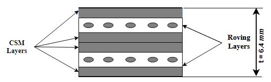
15 Pultruded Polymer Composites Pultruded polymer composites are produced by the process called pultrusion Figure 1. These pultruded composites usually consist of fiber reinforcement, polymer resin, filler particles, small amounts of catalyst and anti-ultraviolet additives and some unwanted voids. The composite can be divided into stacking sequence of two layers. The roving layer which consists of roving fibers and matrix and the second layer is known as CSM layer which is the combination of continuous strand mat in resin matrix these layers are stacked one above the other in sequence as shown in Figure 2. Generally, pultrusion devices pull continuous roving fiber and continuous mats fiber through a resin bath, a performing fixture, a heated cure die, to obtain a final composite product. Figure 1: Schematic of Pultrusion Process [11] 3
![Figure 2: Roving Layer and MAT layers of a pultruded composite sample [4] The matrix further consists of resin,](/docs-images/75/72257176/images/16-0.jpg "filler, voids, a small amount of catalyst, anti-ultraviolet additives and pigments.")

16 Figure 2: Roving Layer and MAT layers of a pultruded composite sample [4] The matrix further consists of resin, filler, voids, a small amount of catalyst, anti-ultraviolet additives and pigments. The filler is added to improve the resin properties such as shrinkage reduction, surface hardness, load transfer and cost reduction. The typical matrix structure is shown in Figure 3. Figure 3: A sketch showing the matrix containing spherical inhomogeneties [4] 4
17 Figure 4: Composite properties structure The fillers are added to the matrix, it has been shown that dramatic improvements in mechanical properties can be achieved by adding a few percentages of clay particles in the matrix material. Polymer composites containing particles with small aspect ratio have also been studied because of their technological and scientific importance. Many studies have been conducted on the mechanical properties of these particulate filled polymer composites and found that modulus and stiffness can be readily increased by adding micro or nano-sized particle. However, the strength directly depends on the stress transfer between particles and the matrix. So for well-bonded particles, the stress can be effectively transferred to the particles which clearly improves the strength [11-13] also in case of poorly bonded particles the strength may reduce due to the addition of particles [12]. 5
18 2. Micromechanical Theories There are several methods used to determine the properties of the polymer composites without considering the size effect of the particles, one such method used in this study is a micromechanical analysis of composite materials in which the properties are determined by looking at the properties of individual constituents that make the composite. These methods include the Eshelby model, Mori-Tanaka model and the Self-Consistent model and some of the modified versions of these models which include void and filler contents. Theoretical Analysis of Matrix Material Modified Eshelby Model This model considers resin, filler and voids whereg, G r and G filler are shear moduli and K, K r and K filler are bulk moduli of composite, resin matrix, filler respectively, ν filler/m and ν void/m are volume fraction of filler and void [4]. G = G r {1 υ filler/m(g filler G r ) G r + 2S 1212 (G filler G r ) υ 1 void/m( G r ) (1) G r + 2S 1212 ( G r ) } K = K r {1 1 υ filler/m (K filler K r ) K r + (1/3)S kkll (K filler K r ) υ void/m ( K r ) (2) K r + (1/3)S kkll ( K r ) } S 1212 = ( 3K r + 6G r 15K r + 20G r ) 9K r S kkll = ( ) 3K r + 4G r (3) (4) 6
19 Modified Mori-Tanaka Model: This model was developed by the researchers T. Mori and T. Tanaka and was based upon Eshelby model. This model is used to relate average stress for inhomogeneities to average stress of matrix where the inhomogeneities are assumed to be randomly oriented and evenly distributed. The modified form of Mori-Tanaka was given in [4] and can be written as fallows. G = G r {1 + υ filler/m (G filler G r ) G r + 2S 1212 ν r/m (G filler G r ) + υ void/m ( G r ) G r + 2S 1212 ν r/m ( G r ) } (5) K = K r {1 + υ filler/m (K filler K r ) K r + (1/3)S kkll υ r/m (K filler K r ) + υ void/m ( K r ) K r + (1/3)S kkll υ r/m ( K r ) } (6) S 1212 = ( 3K + 6G ) 15K + 20G (7) 9K S kkll = ( ) 3K + 4G (8) Where υ r/m is volume fraction of resin in the matrix. Self-Consistent Model The self-consistent model was developed and used for conditions where the volume fraction of the inhomogeneities in the homogenous material increases. This is caused by the addition of more inhomogeneities into the material due to which the interaction between these inhomogeneities 7
20 plays a more prominent role with larger inhomogeneity volume fraction. The general forms of selfconsistent model are modified [4] and can be written as follows. G = G r + υ filler/m(g filler G r )G G + 2S 1212 (G filler G ) + υ void/m( G r )G G + 2S 1212 ( G ) (9) K = K r + υ filler/m(k filler K r )K K + (1/3)S kkll (K filler K ) + υ void/m( K r )K K + (1/3)S kkll ( K ) (10) S 1212 = ( 3K + 6G ) 15K + 20G (11) 9K S kkll = ( ) 3K + 4G (12) Once we determine the properties of the matrix material we can compute G compite, E composite and V Composite can be found. 8
21 Theoretical Analysis of Roving Layers The roving layers are made up of unidirectional continuous fibers. These fibers are bonded together in a matrix to form the roving layers. The mechanical properties of the roving layers can be obtained by using one of the micromechanical models. In this study, Chamis models were used to determine the transverse modulus of roving layers. The longitudinal modulus of roving layers can be obtained as follows. E 11/Roving = E f ν f/roving + E m ν m/roving (13) The transverse modulus of the roving layers is determined by using Chamis equation E 22/Roving = E m 1 υ f/roving (1 E m Ef ) (14) The shear modulus of the roving layers can be determined from Chamis model as G 12/Roving = G m 1 υ f/roving (1 G m Gf ) (15) Where E m, G m and E f, G f are Young s and shear modulus of matrix and fiber. The roving layers poisons ratio can also be calculated as V 12/Roving = V f υ f/roving + V m υ m/roving (16) 9
22 V 21/Roving = V 12/Roving E 22/Roving E 11/Roving (17) Theoretical Analysis of CSM layers The CSM layers are made of randomly oriented continuous fibers. These fibers are bonded into the matrix material to form CSM layers. The fibers in the CSM layers are randomly oriented, hence the properties of this layers can be assumed to be isotropic. The properties of the CSM layers can be determined using Tsai-Pagano model as follows. E Mat = 3 8 E E 22 (18) G Mat = 1 8 E E 22 (19) VMat = E Mat 2G Mat 1 (20) Where E Mat, G Mat and V Mat are Young s modulus, shear modulus and Poisson s ratio of the CSM layers and E 11 and E 22 are longitudinal and transverse moduli of unidirectional fibrous composite containing same volume fraction of identical fibers and matrix as that of a CSM layers under consideration. These are obtained from following equations. E 11/Roving = E f υ f/mat + E m υ m/mat (21) E 22/Roving = E m 1 υ f/roving (1 E m Ef ) (22) 10
23 Theoretical Analysis of Properties of Composites The combined properties of the composite can be calculated by using classical laminate theory as follows. E 11/composite = η E11 + η Mat (υ 12/Rovingη E22 + υ Mat η Mat ) 2 η E22 + η Mat (23) E 22/composite = η E22 + η Mat (υ 12/Rovingη E22 + υ Mat η Mat ) 2 η E11 + η Mat (24) G 12/Roving = G 12/Roving υ Roving + G Mat υ Mat (25) V 12/Composite = υ 12/Rovingη E22 + υ Mat η Mat η E22 + η Mat (26) Here η E11 = η E22 = E 11/Roving υ Roving 1 V 12/Roving V 21/Roving (27) E 22/Roving υ Roving 1 V 12/Roving V 21/Roving (28) η Mat = E Matυ Mat 2 1 V Mat (29) 11
24 Calculation of Volume Fraction of the Constituents of Composites The pultruded polymer composites in this study have two different layers, roving and CSM. The volume of the composite can be written in terms of its layers as follows v Composite = v Roving + v Mat (30) v Roving = v f/roving + v m/roving (31) v Mat = v f/mat + v m/mat (32) Here ν Roving, ν Mat, ν f/roving, ν m/roving, ν f/mat and ν m/mat are volumes of roving, mat, roving fiber, roving matrix, mat fiber and mat matrix, respectively. The total volume of the pultruded composites can also be determined as follows v Composite = v f + v m (33) Here v Composite, v f and v m are total volumes of fibers and matrix. The v f and v m can be expressed as show below. v f = v f/roving + v f/mat (34) v m = v m/roving + v m/mat (35) Here v f/roving, v f/mat, v m/roving and v m/mat are volumes of fiber in roving, fiber in mat, volume of matrix in roving and volume of matrix in CSM layer. 12
25 We analyze the volume fraction of the matrix. The volume of matrix is expressed in terms of constituent s volumes as follows v m = v r + v filler + v void (36) Here v r, v filler and v void are volumes of resin, filler and voids contained in the composite respectively. In order to obtain the volume fractions, divide both sides of the equation with v Composite then the following relations are obtained. υ m = υ r + υ filler + υ void (37) υ r = υ filler = υ void = ν r ν Composite (38) ν filler v Composite (39) ν void ν Composite (40) Where υ r, υ filler and υ void are volume fraction of resin, filler, and void within a composite, respectively. Also, the volume fraction of resin, filler and void with respect to matrix material is labeled as υ r/m,υ filler/m and υ void/m υ r/m = υ r υ r + υ filler + υ void (41) 13
26 υ filler/m = υ void/m = These volume fractions should add up to unity as shown below. υ filler υ r + υ filler + υ void (42) υ void υ r + υ filler + υ void (43) υ r/m + υ filler/m + υ void/m = 1 (44) 14
27 3 New Micromechanical Model As seen in the literature most micromechanical models uses volume fractions and properties of constituents to determine the composite properties. The classical micromechanical models can be modified to achieve the size effect inclusion into these models. The classical micromechanical model can be seen in Eq. (1) where S1212 is Eshelby tensor for spherical inclusion given by Eq. (3). The Eshelby tensors for spherical inclusion were derived as in [9]. These Eshelby tensors were derived by following the theory proposed by Cheng [13]. S 1212 = ( 3K r + 6G r 15K r + 20G r ) 3h(a + h)k a 5a 3 (k + 2μ) e h [a cosh a h h sinh a h ] (45) h = γ(2μ + k)/4μk (46) Where K, μ are micropolar moduli and a is the radius of spherical filler particle. The Eshelby tensor component listed by [9] includes classical Eshelby tensor along with a new term that can capture the size effect which is a function of the size of the filler particle. The new model proposed is a combination of the classical micromechanical model which considers both fillers and voids as shown in Eq. (47) and also consists of non-classical Eshelby tensor. G = G r {1 ν filler/m(g filler G r ) G r + 2S 1212 (G filler G r ) ν 1 void/m( G r ) (47) G r + 2S 1212 ( G r ) } 15
28 Here S 1212 = ( 3K r + 6G r 15K r + 20G r ) 3h(a + h)k a 5a 3 (k + 2μ) e h [a cosh a h h sinh a h ] (48) h = γ(2μ + k)/4μk (49) The new combination of these micromechanical models captures the effects of both voids that are present in the matrix while also considering the effect of size of the filler particle on to the overall mechanical properties. Unlike the classical models, these models also predict the mechanical properties with different sizes of the filler particles. 16
29 4 Process and Approaches The research is achieved by two different ways first experimental analysis is made in order to find the mechanical properties of the polymer composites and to evaluate the volume fractions of individual constituents that build up the composites, secondly, the mechanical properties of the composite are evaluated using analytical equations by varying the size of particles. Experimental Analysis The composite specimens are tested to evaluate the shear properties, an asymmetric four-point bending shear fixture and test method [14] were used to obtain these shear properties of materials. Six samples of the polymer composites specimen were tested. The dimensions and shape of the specimen tested are shown in Figure 5. An MTS 810 material testing system was used for applying compression on to the material. In order to determine the shear properties in the pure shear strain region a two-element stacked rosette (CEA WT-350) manufactured by micro measurement group is placed on the specimen as shown in fig no the strain gauges are mounted and cured on to the specimen Figure 6 by using M-bond 200 manufactured by micro measurement by following the step by step procedure provided by the manufacturers. The strain gauges are connected to the MTS conditional amplifier in order to record the shear strain in the composite specimen. The compression load was applied at a rate of 0.15 mm/min and the data was scanned at an interval of every one second. The principal strains are along a ±45º direction to the longitudinal axis. A linear regression method was used to determine the shear modulus from the slope of the stress-strain curve between 0.1% to 0.6% strains with the number of data points always greater than 50. The broken sample is shown in Figure 7. 17

30 Figure 5: Configuration of the tested specimen (Units: mm) Figure 6: A virgin specimen with a strain rosette application 18
 Note: FRC-2, FRC-3, FRC-4 data have been taken from [4] Shear Modulus (GPa) FRC-1 4.40 FRC-2 4.60 FRC-3 4.50 FRC-4 4.")
31 Figure 7: A tested specimen showing shear failure The experimentally determined shear moduli are listed in below Table 1. Where the standard deviation of FRC-1 specimen is less 6%. Table 1: Experimental Properties Specimen Groups (6 Specimens each) Note: FRC-2, FRC-3, FRC-4 data have been taken from [4] Shear Modulus (GPa) FRC FRC FRC FRC Cross-section of the Sample The cross-section of the pultruded polymer composite and the reinforcement scheme is seen in the Figure 8-11 and it contains a combination of E-glass roving, CSM layers, the matrix part consists of vinyl ester resin and kaolin clay filler particles. The mechanical properties of these constituents are listed in the below Table 2. 19


32 Figure 8: Schematic stacking sequence of FRC-1 Figure 9: Schematic stacking sequence of FRC-2 Figure 10: Schematic stacking sequence of FRC-3 20
 E glass fiber 72 29 0.25 2.56 48 Vinylester resin 3.85 1.40 0.37 1.26 4.79 Kaolin clay filler 20 7.69 0.30 2.60 16.")
33 Figure 11: Schematic stacking sequence of FRC-4 Young's Modulus {GPa) Table 2: Properties of Constituents Shear Modulus (GPa) Bulk Modulus (GPa) Density Poisson's Ratio ( g/cm 3 ) E glass fiber Vinylester resin Kaolin clay filler
34 Volume fractions and Density of the Composite Specimen The density of the composite specimen is obtained by performing the experiment ASTM D 792 [15]. Small coupons of samples were cut from the specimens used for shear testing as shown in fig no. The dimensions of the specimen are shown the figure. The average densities of the tested coupons are listed in Table 3. Table 3: Density of Specimens Number of samples Average Density (g/cm 3 ) STD (g/cm 3 ) FRC FRC FRC FRC The mass fractions and volume fractions are calculated for these specimens following the procedure described by [16]. In this method, the specimen is contained in a crucible Figure 12 and is ignited until only ash and carbon remain. Once the resin is completely removed the analysis of the remaining laminate is performed. The volume and volume fractions are calculated by using the measured weights and densities of the constituents of the composites as described in [16].Table no shows the average volume fractions of the constituents of the composites. 22


35 Figure 12: Cross section of specimen after burning test (Dimensions 25 X 25 X 6.5 mm) Figure 13: Post burn-out fiber architecture of pultruded composites 23
36 Table 4: Average Volume Fractions of the Constituents Constituents Symbol FRC-1 FRC-2 FRC-3 FRC-4 Roving E-glass fibers υ f/roving Mat E-glass fibers υ f/mat Vinylester resin υ r Kaolin clay fillers υ filler Total voids υ void Note: FRC-2, FRC-3, FRC-4 data have been taken from [4] Table 5: Average Volume fractions of CSM and Roving Layers Layer Symbol FRC-1 FRC-2 FRC-3 FRC-4 Roving υ Roving CSM υ CSM
37 5. Results and Discussion In this section, the micromechanical method will be validated by some numerical examples. Initially, the properties of the matrix containing resin, filler and void are determined by using modified Eshelby model [4], and the properties of roving layers and CSM layers are determined by using Chamis micromechanical model and the overall composites are evaluated by using laminate theory. The volume fractions are evaluated as described in [16] and are shown in table [6]. Table 6: Comparison of Experimental and Theoretical Shear Modulus Classical micromechanical model Ratio Size effect included Ratio Sample exp G 12 G 12 G 12 FRC FRC FRC FRC The results in Table 6 shows the shear modulus of the composite specimens. It can be seen that the results are compared between experimental and analytical models. A significant difference can be seen between the classical micromechanical models and the experimentally determined shear modulus for different composites specimens. The modulus obtained from the new model gives more close results when compared with results obtained from experiments. In the next case, the size of the filler particle is varied by assuming a constant characteristic length of 17µm and varying the radius between 1to100 times the characteristic length the trend can be observed as the model captures the size effect of the particle as the ratio of a/l increases the Eshelby tensor component also increase. The Figures 14-17, shows the trends of Eshelby tensor and a/l. It can be seen from the figures that as the size of the particle (a) increases the value of 25
38 S1212 also increases, unlike the classical part which is constant and is independent of size. When the radius of the particle gets smaller with constant characteristic length S1212 gets much smaller compared to the classical, however, as the size of the particle is increased the value of S1212 increases from below and tries to approach classical S S a/l Figure 14: S1212 varying with inclusion radius for FRC S a/l Figure 15: S1212 varying with inclusion radius for FRC-2 26
39 S a/l Figure 16: S1212 Varying with inclusion radius FRC S a/l Figure 17: S1212 Varying with inclusion radius FRC-4 The graphs of FRC-3 and FRC-4 are almost similar as they have almost same volume fractions of the individual constituents. The shear modulus of the composites increases with the increase in the volume fraction but as the size increases the modulus starts decreasing. This effect is caused due to weak bonding for particles with a larger radius. 27
40 G 12 (GPa) a/l=1 a/l=50 a/l= V f (Filler Volume Fraction) Figure 18: Variation in shear modulus for FRC-1 G 12 (GPa) a/l=1 a/l=50 a/l= V f (Filler Volume Fraction) Figure 19: Variation in shear modulus for FRC-2 28
41 G 12 (GPa) G 12 ( GPa) a/l=1 a/l=50 a/l= V f (Filler Volume Fraction) Figure 20: Variation in shear modulus for FRC-3 The Same trend can be observed in Figures The different composite specimens show the same effect with the change in the size of particle and volume fraction the modulus varies, this is because the smaller particle sized filler has a higher total surface area for a given loading. This shows that strength increases with increase in surface area of the filled particles through a more efficient stress transfer mechanism a/l=1 a/l=50 a/l= V f (Filler Volume Fraction) Figure 21: Variation in shear modulus for FRC-4 29
42 6 Conclusions and Further works This research reveals the results obtained from an analytical and experimental investigation in determining the properties of pultruded polymer composites. It presents the procedure of analyzing, evaluating and validating the micromechanical models. The new model equations can predict the mechanical properties of matrix considering size effect, filler and void in the matrix, the properties of the matrix are evaluated using classical micromechanical model and newly proposed analytical equations. The results of this research suggest considering the size of the particle while estimating the properties of the composites to get a more accurate prediction of the properties. The analytical and experimental results were examined and the results show that the proposed model captures the size effect and also predicts the properties more closely to the experimentally determined results than the classical micromechanical theories. The components of the averaged Eshelby tensor are found to be decreasing as the inclusion radius decreases with constant characteristic length and also this component of Eshelby tensor values are found to be increasing as the inclusion size is increased and approaches the classical tensor value when the inclusion size is large enough. The size effects of the voids have not been considered in this study hence future works can be dedicated to create a new model that can predict the effect of void sizes on the properties of the composites. 30
43 Bibliography [1] J. Eshelby, "The determination of the elastic field of an ellipsoidal inclusion, and related problems," The Royal Society, [2] T. Mori and k. Tanaka, "Average stress in matrix and average elastic energy of materials with misfitting inclusions," Acta Metallurgica, [3] A. Hershey, "The elasticity of an anisotropic aggregare of anisotropic cubic crystals," Journal of applied mechanics, vol. 21, no. 3, pp , [4] J. Y. Park and A.-H. Zureick, "Effect of filler and void content on mechanical properties of pultruded composite materials under shear loading," Polymer Composites, vol. 26(2), pp , [5] J. Y. Park and Lee.N, "Shape effect of platelet clay filler on mechanical behaviors of pultruded polymer composites under shear loading," Journal of reinforced plastics and composites, vol. 26, no. 6, pp , [6] D. Lloyd, "Particle reinforced aluminium and magnesium matrix composites," International material reviews, vol. 39, no. 1, pp. 1-23, [7] J. Yang, M. H. F. Z. R. M. C. Cady and A. Evans, "Effects of damage on the flow strength and ductility of a ductile Al alloy reinforced with sic particulates," Acta Metallurgica Materialia, vol. 38, no. 12, pp ,
44 [8] F. Xun and Z. H. Gengkai Hu, "Effective in plane moduli of composite with a micropolar matrix and coated fibers," International Journal of Solids and Structures, vol. 41, no. 1, pp , [9] X. Liu and G. HU, "A continuum micromechanical theory of overall plasticity for particulate composites including particle size effect," International journal of plasticity, vol. 26(2), pp , [10] Joseph H. Koo, Polymer Nanocomposites: Processing, Characterization, and Applications, The McGraw-Hill Companies, Inc, [11] A. Landesmann, C. A. Seruti and E. d. M. Batista, "Mechanical Properties of Glass Fiber Reinforced Polymers Members for Structural Applications," Materials Research, vol. 18, no. 6, pp , [12] L.Nicolais and L. Nicodemo, "The Effect of Particles Shape on Tensile Properties of Glassy Thermoplastic Composites," International Journal of Polymeric Materials and Polymeric Biomaterials, vol. 3, no. 3, pp , [13] Z.-Q. CHENG and L.-H. HE, "MICROPOLAR ELASTIC FIELDS DUE TO A SPHERICAL INCLUSION," International Journal of Engineering Science, vol. 33, no. 3, pp , [14] ASTM D5379, "Standard test method for shear properties of composite materials by V- notched beam," American Soceity for Testing Materials,
45 [15] A. D792, Standard Test Methods for Density and Specific Gravity (Relative Density) of Plastics by Displacement1, Philadelphia : American Society of Testing Materials, [16] B. S.Ye and A. L. Svenson, "Mass and volume fraction properties of pultruded glass fiberreinforced composites," Composites, vol. 26, no. 10, pp , [17] J. Halpin, "Effects of Environmental factors on Composite Materials," Air Force Materials Laboratory, Ohio, [18] B. Pukanszky and G. Voros, "Mechanism of interfacial interactions in particulate filled composites," Composite Interfaces, vol. 1, no. 5, pp , [19] n. Nakamura, M. Yamaguchi, M. Okubo and T. Matsumoto, "Effects of particle size on mechanical and impact properties of epoxy resin filled with spherical silica," Applied Polymer Science, vol. 45, no. 7, pp , [20] E.Reynaud, T.Jouen, C.Gauthier, G.Vigier and J.Varlet, "Nanofillers in polymeric matrix: a study on silica reinforced PA6," Polymer, vol. 42, no. 21, pp , [21] S.-Y. Fu and B. Lauke, "Characterization of tensile behavior of hybrid short glass fibre/calcite particle," ABS composites, vol. 29, no. A, pp , [22] C. Chamis, Simplified Composite Micromechanics Equations for Hygral,Thermal and Mechanical properties, Sample Quaterly,
Module 7: Micromechanics Lecture 34: Self Consistent, Mori -Tanaka and Halpin -Tsai Models. Introduction. The Lecture Contains. Self Consistent Method
 Introduction In this lecture we will introduce some more micromechanical methods to predict the effective properties of the composite. Here we will introduce expressions for the effective properties without
CHAPTER 4 MODELING OF MECHANICAL PROPERTIES OF POLYMER COMPOSITES
 CHAPTER 4 MODELING OF MECHANICAL PROPERTIES OF POLYMER COMPOSITES 4. Introduction Fillers added to polymer matrices as additives are generally intended for decreasing the cost (by increase in bulk) of
Mechanical and Thermal Properties of Coir Fiber Reinforced Epoxy Composites Using a Micromechanical Approach
 Mechanical and Thermal Properties of Coir Fiber Reinforced Epoxy Composites Using a Micromechanical Approach Sandhyarani Biswas Department of Mechanical Engineering, N.I.T Rourkela, INDIA Abstract: Now-a-days,
3D Compression Molding
 Autodesk Simulation Moldflow Insight 2014 3D Compression Molding Executive summary In this work, the simulation results from a program developed for the three-dimensional analysis of compression molding
Determination of the Shear Buckling Load of a Large Polymer Composite I-Section Using Strain and Displacement Sensors
 Sensors 2012, 12, 16024-16036; doi:10.3390/s121216024 Article OPEN ACCESS sensors ISSN 1424-8220 www.mdpi.com/journal/sensors Determination of the Shear Buckling Load of a Large Polymer Composite I-Section
Effect of Interlayers on Mechanical Properties and Interfacial Stress Transfer of 2D Layered Graphene- Polymer Nanocompsites
 University of Kentucky UKnowledge Theses and Dissertations--Mechanical Engineering Mechanical Engineering 2017 Effect of Interlayers on Mechanical Properties and Interfacial Stress Transfer of 2D Layered
MODELLING INTERACTION EFFECT OF NANOSILICA PARTICLES ON NANOSILICA/EPOXY COMPOSITE STIFFNESS
 MODELLING INTERACTION EFFECT OF NANOSILICA PARTICLES ON NANOSILICA/EPOXY COMPOSITE STIFFNESS Mulyadi a*, I. Gitman a, C. Pinna a, C. Soutis b a Department of Mechanical Engineering, The University of Sheffield,
Micromechanical analysis of FRP hybrid composite lamina for in-plane transverse loading
 Indian Journal of Engineering & Materials Sciences Vol. 15, October 2008, pp. 382-390 Micromechanical analysis of FRP hybrid composite lamina for in-plane transverse loading K Sivaji Babu a *, K Mohana
VALIDATION of CoDA SOFTWARE for COMPOSITES SYNTHESIS AND PRELIMINARY DESIGN (or GETTING COMPOSITES USED - PART 2 )
") VALIDATION of CoDA SOFTWARE for COMPOSITES SYNTHESIS AND PRELIMINARY DESIGN (or GETTING COMPOSITES USED - PART 2 ) Graham D Sims and William R Broughton Composites Design Data and Methods, Centre for Materials
VALIDATION of CoDA SOFTWARE for COMPOSITES SYNTHESIS AND PRELIMINARY DESIGN (or GETTING COMPOSITES USED - PART 2 ) Graham D Sims and William R Broughton Composites Design Data and Methods, Centre for Materials
Micromechanics modeling for the stiffness and strength properties of glass fibers/cnts/epoxy composites
 High Performance Structures and Materials V 279 Micromechanics modeling for the stiffness and strength properties of glass fibers/cnts/epoxy composites M. Kim, F. A. Mirza & J. I. Song School of Mechatronics
American Society for Testing and Materials (ASTM) Standards. Mechanical Testing of Composites and their Constituents
 Standards. Mechanical Testing of Composites and their Constituents") Mechanical Testing of Composites and their Constituents American Society for Testing and Materials (ASTM) Standards Tests done to determine intrinsic material properties such as modulus and strength for
Mechanical Testing of Composites and their Constituents American Society for Testing and Materials (ASTM) Standards Tests done to determine intrinsic material properties such as modulus and strength for
IJSER 1. INTRODUCTION. M.Elhadary
 1591 A new failure criterion for GRP composite materials subjected to in-phase and out-of-phase biaxial fatigue loading under different stress ratios M.Elhadary Abstract this studying the fatigue behavior
Generic Strategies to Implement Material Grading in Finite Element Methods for Isotropic and Anisotropic Materials
 University of Nebraska - Lincoln DigitalCommons@University of Nebraska - Lincoln Engineering Mechanics Dissertations & Theses Mechanical & Materials Engineering, Department of Winter 12-9-2011 Generic
Module III - Macro-mechanics of Lamina. Lecture 23. Macro-Mechanics of Lamina
 Module III - Macro-mechanics of Lamina Lecture 23 Macro-Mechanics of Lamina For better understanding of the macromechanics of lamina, the knowledge of the material properties in essential. Therefore, the
Development of a code to generate randomly distributed short fiber composites to estimate mechanical properties using FEM
 International Journal of Theoretical and Applied Mechanics. ISSN 0973-6085 Volume 12, Number 4 (2017) pp. 863-872 Research India Publications http://www.ripublication.com Development of a code to generate
TABLE OF CONTENTS. Mechanics of Composite Materials, Second Edition Autar K Kaw University of South Florida, Tampa, USA
 Mechanics of Composite Materials, Second Edition Autar K Kaw University of South Florida, Tampa, USA TABLE OF CONTENTS 1. INTRODUCTION TO COMPOSITE MATERIALS 1.1 Introduction... 1.2 Classification... 1.2.1
ISSN: ISO 9001:2008 Certified International Journal of Engineering Science and Innovative Technology (IJESIT) Volume 2, Issue 4, July 2013
 Volume 2, Issue 4, July 2013") Delamination Studies in Fibre-Reinforced Polymer Composites K.Kantha Rao, Dr P. Shailesh, K. Vijay Kumar 1 Associate Professor, Narasimha Reddy Engineering College Hyderabad. 2 Professor, St. Peter s Engineering
Delamination Studies in Fibre-Reinforced Polymer Composites K.Kantha Rao, Dr P. Shailesh, K. Vijay Kumar 1 Associate Professor, Narasimha Reddy Engineering College Hyderabad. 2 Professor, St. Peter s Engineering
Evaluation of Effective Elastic Moduli Using Micromechanics
 IOP Conference Series: Materials Science and Engineering PAPER OPEN ACCESS Evaluation of Effective Elastic Moduli Using Micromechanics To cite this article: Misba Mehdi Mrs. et al 2018 IOP Conf. Ser.:
Effect of Specimen Dimensions on Flexural Modulus in a 3-Point Bending Test
 Effect of Specimen Dimensions on Flexural Modulus in a 3-Point Bending Test M. Praveen Kumar 1 and V. Balakrishna Murthy 2* 1 Mechanical Engineering Department, P.V.P. Siddhartha Institute of Technology,
Passive Damping Characteristics of Carbon Epoxy Composite Plates
 Journal of Materials Science and Engineering A 6 (-) 35-4 doi:.765/6-63/6.-.5 D DAVID PUBLISHING Passive Damping Characteristics of Carbon Epoxy Composite Plates Dileep Kumar K * and V V Subba Rao Faculty
Effects of geometry and properties of fibre and matrix on overall. composite parameters
 Int. Journal of Applied Sciences and ngineering Research, ol. 3, Issue 4, 2014 www.ijaser.com 2014 by the authors Licensee IJASR- Under Creative Commons License 3.0 editorial@ijaser.com Research article
Non-conventional Glass fiber NCF composites with thermoset and thermoplastic matrices. F Talence, France Le Cheylard, France
 20 th International Conference on Composite Materials Copenhagen, 19-24th July 2015 Non-conventional Glass fiber NCF composites with thermoset and thermoplastic matrices. Thierry Lorriot 1, Jalal El Yagoubi
DAMAGE MECHANICS MODEL FOR OFF-AXIS FATIGUE BEHAVIOR OF UNIDIRECTIONAL CARBON FIBER-REINFORCED COMPOSITES AT ROOM AND HIGH TEMPERATURES
 DAMAGE MECHANICS MODEL FOR OFF-AXIS FATIGUE BEHAVIOR OF UNIDIRECTIONAL CARBON FIBER-REINFORCED COMPOSITES AT ROOM AND HIGH TEMPERATURES M. Kawai Institute of Engineering Mechanics University of Tsukuba,
Computational Analysis for Composites
 Computational Analysis for Composites Professor Johann Sienz and Dr. Tony Murmu Swansea University July, 011 The topics covered include: OUTLINE Overview of composites and their applications Micromechanics
STRESS ANALYSIS OF BONDED JOINTS IN PULTRUDED GRP COMPONENTS
 16 TH INTERNATIONAL CONFERENCE ON COMPOSITE MATERIALS STRESS ANALYSIS OF BONDED JOINTS IN PULTRUDED GRP COMPONENTS S.W. Boyd*, J. M. Dulieu-Barton*, O. T. Thomsen**, A.Gherardi* [J.M. Dulieu-Barton]: janice@soton.ac.uk
CHEM-E2200: Polymer blends and composites Fibre architecture and principles of reinforcement
 CHEM-E2200: Polymer blends and composites Fibre architecture and principles of reinforcement Mark Hughes 19 th September 2016 Outline Fibre architecture Volume fraction and the rule of mixtures Principle
Continuum Modeling Techniques to Determine Mechanical Properties of Nanocomposites
 International OPEN ACCESS Journal Of Modern Engineering Research (IJMER) Continuum Modeling Techniques to Determine Mechanical Properties of Nanocomposites Sonali Gholap 1, Dr. Dhananjay R. Panchagade
MICROMECHANICAL ANALYSIS OF FRP COMPOSITES SUBJECTED TO LONGITUDINAL LOADING
 MICROMECHANICAL ANALYSIS OF FRP COMPOSITES SUBJECTED TO LONGITUDINAL LOADING N. Krishna Vihari 1, P. Phani Prasanthi 1, V. Bala Krishna Murthy 2* and A. Srihari Prasad 3 1 Mech. Engg. Dept., P. V. P. Siddhartha
Aspect Ratio Requirements for Nanotube-Reinforced, Polymer-Matrix Composites
 Aspect Ratio Requirements for Nanotube-Reinforced, Polymer-Matrix Composites J.A.Nairn Wood Science and Engineering, Oregon State University, Corvallis, OR 97330, USA Abstract A fiber s efficiency in a
THE INFLUENCE OF IN-PLANE DENSITY VARIATION ON ENGINEERING PROPERTIES OF ORIENTED STRANDBOARD: A FINITE ELEMENT SIMULATION
 Proceedings of McMat5: 5 Joint ASME/ASCE/SES Conference on Mechanics and Materials June 1-3, 5, Baton Rouge, Louisiana, USA 255 THE INFLUENCE OF IN-PLANE DENSITY VARIATION ON ENGINEERING PROPERTIES OF
Material Characterization of Carbon Fiber Reinforced Polymer Laminate Using Virtual Fields Method
 Proceedings of ICTACEM 014 International Conference on Theoretical, Applied, Computational and Experimental Mechanics December 9-31, 014, IIT Kharagpur, India ICTACEM-014/39 Material Characterization of
Composite models 30 and 131: Ply types 0 and 8 calibration
 Model calibration Composite Bi-Phase models 30 and 3 for elastic, damage and failure PAM-CRASH material model 30 is for solid and 3 for multi-layered shell elements. Within these models different ply types
PARTICLE SIZE EFFECT FROM MICRO TO NANO ON THE THERMAL AND MECHANICAL PROPERTIES OF POLYMER COMPOSITES
 Indian Institute of Technology Delhi (IITD), New Delhi, 2013 PARTICLE SIZE EFFECT FROM MICRO TO NANO ON THE THERMAL AND MECHANICAL PROPERTIES OF POLYMER COMPOSITES by: M.HOSSEIN ALAEI Department of Applied
CHEM-C2410: Materials Science from Microstructures to Properties Composites: basic principles
 CHEM-C2410: Materials Science from Microstructures to Properties Composites: basic principles Mark Hughes 14 th March 2017 Today s learning outcomes To understand the role of reinforcement, matrix and
STANDARD SAMPLE. Reduced section " Diameter. Diameter. 2" Gauge length. Radius
 MATERIAL PROPERTIES TENSILE MEASUREMENT F l l 0 A 0 F STANDARD SAMPLE Reduced section 2 " 1 4 0.505" Diameter 3 4 " Diameter 2" Gauge length 3 8 " Radius TYPICAL APPARATUS Load cell Extensometer Specimen
QUESTION BANK Composite Materials
 QUESTION BANK Composite Materials 1. Define composite material. 2. What is the need for composite material? 3. Mention important characterits of composite material 4. Give examples for fiber material 5.
Modelling the nonlinear shear stress-strain response of glass fibrereinforced composites. Part II: Model development and finite element simulations
 Modelling the nonlinear shear stress-strain response of glass fibrereinforced composites. Part II: Model development and finite element simulations W. Van Paepegem *, I. De Baere and J. Degrieck Ghent
SOME RESEARCH ON FINITE ELEMENT ANALYSIS OF COMPOSITE MATERIALS
 Mechanical Testing and Diagnosis ISSN 2247 9635, 2012 (II), Volume 3, 79-85 SOME RESEARCH ON FINITE ELEMENT ANALYSIS OF COMPOSITE MATERIALS Valeriu DULGHERU, Viorel BOSTAN, Marin GUŢU Technical University
Lab Exercise #5: Tension and Bending with Strain Gages
 Lab Exercise #5: Tension and Bending with Strain Gages Pre-lab assignment: Yes No Goals: 1. To evaluate tension and bending stress models and Hooke s Law. a. σ = Mc/I and σ = P/A 2. To determine material
An integrated approach to the design of high performance carbon fibre reinforced risers - from micro to macro - scale
 An integrated approach to the design of high performance carbon fibre reinforced risers - from micro to macro - scale Angelos Mintzas 1, Steve Hatton 1, Sarinova Simandjuntak 2, Andrew Little 2, Zhongyi
Nanoindentation of Fibrous Composite Microstructures: Experimentation and Finite Element Investigation. Mark Hardiman
 Nanoindentation of Fibrous Composite Microstructures: Experimentation and Finite Element Investigation Mark Hardiman Materials and Surface Science Institute (MSSI), Department of Mechanical and Aeronautical
N o n l i n e a r M u l t i - S c a l e M o d e l i n g o f A e r o s p a c e C o m p o s i t e s M a t e r i a l s & S t r u c t u r e s
 N o n l i n e a r M u l t i - S c a l e M o d e l i n g o f A e r o s p a c e C o m p o s i t e s M a t e r i a l s & S t r u c t u r e s R o g e r A. A s s a k e r C E O, e - X s t r e a m e n g i n e
An Elasto-Visco-Plastic Multiscale Model for Fibrous Unidirectional Composite Materials
 An Elasto-Visco-Plastic Multiscale Model for Fibrous Unidirectional Composite Materials by Shari Lynn King A thesis presented to the University of Waterloo in fulfillment of the thesis requirement for
DIGIMAT for NANO-COMPOSITES
 DIGIMAT for NANO-COMPOSITES Document Version 2.0.1, February 2010 info@e-xstream.com www.e-xstream.com Materials: Engineering Plastics, Reinforced Plastics, Mineral and Clay fillers. e-xstream Technology:
KINK BAND FORMATION OF FIBER REINFORCED POLYMER (FRP)
") KINK BAND FORMATION OF FIBER REINFORCED POLYMER (FRP) 1 University of Science & Technology Beijing, China, niukm@ustb.edu.cn 2 Tsinghua University, Department of Engineering Mechanics, Beijing, China,
KINK BAND FORMATION OF FIBER REINFORCED POLYMER (FRP) 1 University of Science & Technology Beijing, China, niukm@ustb.edu.cn 2 Tsinghua University, Department of Engineering Mechanics, Beijing, China,
Module 7: Micromechanics Lecture 29: Background of Concentric Cylinder Assemblage Model. Introduction. The Lecture Contains
 Introduction In this lecture we are going to introduce a new micromechanics model to determine the fibrous composite effective properties in terms of properties of its individual phases. In this model
Mechanical Properties of Fiber Reinforced Composites Using Buckminster Fullerene Reinforcement
 IJRMET Vo l. 4, Is s u e Sp l - 1, No v 2013- Ap r i l 2014 ISSN : 2249-5762 (Online ISSN : 2249-5770 (Print Mechanical Properties of Fiber Reinforced Composites Using Buckminster Fullerene Reinforcement
Prediction of Micromechanical Behaviour of Elliptical Frp Composites
 Prediction of Micromechanical Behaviour of Elliptical Frp Composites Kiranmayee.Nerusu Dept. of Mechanical Engg. P. V. P. Siddhartha Institute of Technology, Vijayawada 520 007, A.P, India. P. Phani Prasanthi
Assessment Methods of Mechanical Properties of Composite Materials
 Mechanics and Mechanical Engineering Vol. 21, No. 4 (2017) 1005 1018 c Lodz University of Technology Assessment Methods of Mechanical Properties of Composite Materials Monika Kamocka Radoslaw J. Mania
AN EFFECTIVE SOLUTION OF THE COMPOSITE (FGM S) BEAM STRUCTURES
 BEAM STRUCTURES") Engineering MECHANICS, Vol. 15, 2008, No. 2, p. 115 132 115 AN EFFECTIVE SOLUTION OF THE COMPOSITE (FGM S) BEAM STRUCTURES Justín Murín, Vladimír Kutiš* The additive mixture rules have been extended for
Engineering MECHANICS, Vol. 15, 2008, No. 2, p. 115 132 115 AN EFFECTIVE SOLUTION OF THE COMPOSITE (FGM S) BEAM STRUCTURES Justín Murín, Vladimír Kutiš* The additive mixture rules have been extended for
Finite Element of Composite Materials with Partial Debonding along Boundary. Kohei HIGUCHI, Tetsuo IWAKUMA
 Vol. 8 (2005 8 ) Finite Element of Composite aterials with Partial Debonding along Boundary Kohei HIGUCHI, Tetsuo IWAKUA JFE PhD 980-8579 6-6-06 Damages in composite materials are mostly governed by interfacial
Open-hole compressive strength prediction of CFRP composite laminates
 Open-hole compressive strength prediction of CFRP composite laminates O. İnal 1, A. Ataş 2,* 1 Department of Mechanical Engineering, Balikesir University, Balikesir, 10145, Turkey, inal@balikesir.edu.tr
MICROMECHANICAL DEFORMATIONS IN PARTICULATE FILLED POLYMERS: THE EFFECT OF ADHESION
 MICROMECHANICAL DEFORMATIONS IN PARTICULATE FILLED POLYMERS: THE EFFECT OF ADHESION K. Renner, J. Móczó, B. Pukánszky Laboratory of Plastics and Rubber Technology, Department of Physical Chemistry and
Predicting Elastic Properties of Unidirectional SU8/ZnO Nanocomposites using COMSOL Multiphysics
 Predicting Elastic Properties of Unidirectional SU8/ZnO Nanocomposites using COMSOL Multiphysics Neelam Mishra 1, and Kaushik Das *1 1 School of Minerals Metallurgical and Materials Engineering, Indian
Buckling Behavior of 3D Randomly Oriented CNT Reinforced Nanocomposite Plate
 Buckling Behavior of 3D Randomly Oriented CNT Reinforced Nanocomposite Plate Outline Introduction Representative Volume Element (RVE) Periodic Boundary Conditions on RVE Homogenization Method Analytical
ME 582 Advanced Materials Science. Chapter 2 Macromechanical Analysis of a Lamina (Part 2)
") ME 582 Advanced Materials Science Chapter 2 Macromechanical Analysis of a Lamina (Part 2) Laboratory for Composite Materials Research Department of Mechanical Engineering University of South Alabama, Mobile,
ME 582 Advanced Materials Science Chapter 2 Macromechanical Analysis of a Lamina (Part 2) Laboratory for Composite Materials Research Department of Mechanical Engineering University of South Alabama, Mobile,
Hygrothermal stresses in laminates
 Hygrothermal stresses in laminates Changing environment conditions (temperature and moisture) have an important effect on the properties which are matrix dominated. Change in temperaturet and moisture
Most of the material in this package is based on a recently published book. This is:
 Mechanics of Composite Materials Version 2.1 Bill Clyne, University of Cambridge Boban Tanovic, MATTER Assumed Pre-knowledge It is assumed that the student is familiar with simple concepts of mechanical
Research Article Effects of CNT Diameter on the Uniaxial Stress-Strain Behavior of CNT/Epoxy Composites
 Nanomaterials Volume 28, Article ID 834248, 6 pages doi:1.11/28/834248 Research Article Effects of CNT Diameter on the Uniaxial Stress-Strain Behavior of CNT/Epoxy Composites N. Yu and Y. W. Chang Department
Prediction of Elastic Constants on 3D Four-directional Braided
 Prediction of Elastic Constants on 3D Four-directional Braided Composites Prediction of Elastic Constants on 3D Four-directional Braided Composites Liang Dao Zhou 1,2,* and Zhuo Zhuang 1 1 School of Aerospace,
Failure analysis of serial pinned joints in composite materials
 Indian Journal of Engineering & Materials Sciences Vol. 18, April 2011, pp. 102-110 Failure analysis of serial pinned joints in composite materials Alaattin Aktaş* Department of Mechanical Engineering,
FLEXURAL RESPONSE OF FIBER RENFORCED PLASTIC DECKS USING HIGHER-ORDER SHEAR DEFORMABLE PLATE THEORY
 Asia-Pacific Conference on FRP in Structures (APFIS 2007) S.T. Smith (ed) 2007 International Institute for FRP in Construction FLEXURAL RESPONSE OF FIBER RENFORCED PLASTIC DECKS USING HIGHER-ORDER SHEAR
Mechanical Properties
 Mechanical Properties Elastic deformation Plastic deformation Fracture I. Elastic Deformation S s u s y e u e T I II III e For a typical ductile metal: I. Elastic deformation II. Stable plastic deformation
DYNAMIC RESPONSE OF SYNTACTIC FOAM CORE SANDWICH USING A MULTIPLE SCALES BASED ASYMPTOTIC METHOD
 ECCM6-6 TH EUROPEAN CONFERENCE ON COMPOSITE MATERIALS, Seville, Spain, -6 June 4 DYNAMIC RESPONSE OF SYNTACTIC FOAM CORE SANDWICH USING A MULTIPLE SCALES BASED ASYMPTOTIC METHOD K. V. Nagendra Gopal a*,
Enhancing Prediction Accuracy In Sift Theory
 18 TH INTERNATIONAL CONFERENCE ON COMPOSITE MATERIALS Enhancing Prediction Accuracy In Sift Theory J. Wang 1 *, W. K. Chiu 1 Defence Science and Technology Organisation, Fishermans Bend, Australia, Department
Strength of GRP-laminates with multiple fragment damages
 Strength of GRP-laminates with multiple fragment damages S. Kazemahvazi, J. Kiele, D. Zenkert Kungliga Tekniska Högskolan, KTH 100 44 Stockholm, Sweden sohrabk@kth.se SUMMARY The strength of glass fibre
Prediction of The Ultimate Strength of Composite Laminates Under In-Plane Loading Using A Probabilistic Approach
 Prediction of the Ultimate Strength of Composite Laminates Under In-Plane Loading Prediction of The Ultimate Strength of Composite Laminates Under In-Plane Loading Using A Probabilistic Approach Tae Jin
MESH MODELING OF ANGLE-PLY LAMINATED COMPOSITE PLATES FOR DNS AND IPSAP
 16 TH INTERNATIONAL CONFERENCE ON COMPOSITE MATERIALS MESH MODELING OF ANGLE-PLY LAMINATED COMPOSITE PLATES FOR DNS AND IPSAP Wanil Byun*, Seung Jo Kim*, Joris Wismans** *Seoul National University, Republic
Stress, Strain Stress strain relationships for different types of materials Stress strain relationships for a unidirectional/bidirectional lamina
 Chapter 2 Macromechanical Analysis of a Lamina Stress, Strain Stress strain relationships for different types of materials Stress strain relationships for a unidirectional/bidirectional lamina Islamic
Mechanical Behavior of Fullerene Reinforced Fiber Composites with Interface Defects through Homogenization Approach and Finite Element Method
 , pp.67-82 http://dx.doi.org/1.14257/ijast.215.78.6 Mechanical Behavior of Fullerene Reinforced Fiber Composites with Interface Defects through Homogenization Approach and Finite Element Method P. Prasanthi
Tensile Properties of Thermoplastic-Laminated Composites Based on a Polypropylene Matrix Reinforced with Continuous Twaron Fibers
 Tensile Properties of Thermoplastic-Laminated Composites Based on a Polypropylene Matrix Reinforced with Continuous Twaron Fibers J. L. MENA-TUN, P. I. GONZALEZ-CHI Centro de Investigación Científica de
ULTRASONIC MEASUREMENT OF IN-PLANE MODULI OF PULTRUDED COMPOSITES
 ULTRASONIC MEASUREMENT OF IN-PLANE MODULI OF PULTRUDED COMPOSITES R. Prabhakaran 1, M. Saha 2, and T. Galloway 3 1,2 Department of Mechanical Engineering, Old Dominion University Norfolk, Virginia 23529,
Anisotropic modeling of short fibers reinforced thermoplastics materials with LS-DYNA
 Anisotropic modeling of short fibers reinforced thermoplastics materials with LS-DYNA Alexandre Hatt 1 1 Faurecia Automotive Seating, Simplified Limited Liability Company 1 Abstract / Summary Polymer thermoplastics
THE ROLE OF DELAMINATION IN NOTCHED AND UNNOTCHED TENSILE STRENGTH
 THE ROLE OF DELAMINATION IN NOTCHED AND UNNOTCHED TENSILE STRENGTH M. R. Wisnom University of Bristol Advanced Composites Centre for Innovation and Science University Walk, Bristol BS8 1TR, UK M.Wisnom@bristol.ac.uk
Multi Disciplinary Delamination Studies In Frp Composites Using 3d Finite Element Analysis Mohan Rentala
 Multi Disciplinary Delamination Studies In Frp Composites Using 3d Finite Element Analysis Mohan Rentala Abstract: FRP laminated composites have been extensively used in Aerospace and allied industries
PROPERTY CALCULATION SYSTEM FOR INJECTION MOLDING AND COMPRESSION MOLDING OF FIBER-FILLED POLYMER COMPOSITES
 PROPERTY CALCULATION SYSTEM FOR INJECTION MOLDING AND COMPRESSION MOLDING OF FIBER-FILLED POLYMER COMPOSITES X. Jin *, J. Wang, S. Han Autodesk Inc., 353 N. Triphammer Rd., Ithaca, NY, 485, U.S.A. Corning
Elastic parameters prediction under dynamic loading based on the. unit cell of composites considering end constraint effect
 Elastic parameters prediction under dynamic loading based on the unit cell of composites considering end constraint effect Wang Meng 1,, Fei Qingguo 1,, Zhang Peiwei 1, (1. Institute of Aerospace Machinery
Analysis of Flexural Properties of Carbon Fiber Reinforced / E-Poxy Composite Material
 ISSN 2395-1621 Analysis of Flexural Properties of Carbon Fiber Reinforced / E-Poxy Composite Material #1 Kishor Shingare, #2 Dr. S.M. Shendokar, #3 Prof. P.V. Deshmukh, #4 Prof. S.S. Chavan 1 kishorshingare911@gmail.com
Comparison of Ply-wise Stress-Strain results for graphite/epoxy laminated plate subjected to in-plane normal loads using CLT and ANSYS ACP PrepPost
 Comparison of Ply-wise Stress-Strain results for graphite/epoxy laminated plate subjected to in-plane normal loads using CLT and ANSYS ACP PrepPost 1 Mihir A. Mehta, 2 Satyen D. Ramani 1 PG Student, Department
Matteo Basso *, Ahmed Elmarakbi. d Arco, Italy
 International Conference on Automotive Composites ICAutoC 2016 A. Elmarakbi and A.L. Araújo (Editors) IDMEC 2016 Multiscale Analysis of the Mechanical Performance improvement of composites CFRP laminates,
A coupled field finite element model to predict actuation properties of piezoelectrically actuated bistable composites.
 A coupled field finite element model to predict actuation properties of piezoelectrically actuated bistable composites. P.F.Giddings, C.R.Bowen, H.A.Kim University of Bath, UK Dept. Mech. ng, University
THE MUTUAL EFFECTS OF SHEAR AND TRANSVERSE DAMAGE IN POLYMERIC COMPOSITES
 THE 19 TH INTERNATIONAL CONFERENCE ON COMPOSITE MATERIALS THE MUTUAL EFFECTS OF SHEAR AND TRANSVERSE DAMAGE IN POLYMERIC COMPOSITES L.V. Smith 1 *, M. Salavatian 1 1 School of Mechanical and Materials
FROM PROCESS MODELING TO ELASTIC PROPERTY PREDICTION FOR LONG-FIBER INJECTION-MOLDED THERMOPLASTICS 1
 FROM PROCESS MODELING TO ELASTIC PROPERTY PREDICTION FOR LONG-FIBER INJECTION-MOLDED THERMOPLASTICS 1 Ba Nghiep Nguyen 2 (a), Vlastimil Kunc (b), Barbara J. Frame (b), Jay H. Phelps (c), Charles L. Tucker
MATERIAL MECHANICS, SE2126 COMPUTER LAB 4 MICRO MECHANICS. E E v E E E E E v E E + + = m f f. f f
 MATRIAL MCHANICS, S226 COMPUTR LAB 4 MICRO MCHANICS 2 2 2 f m f f m T m f m f f m v v + + = + PART A SPHRICAL PARTICL INCLUSION Consider a solid granular material, a so called particle composite, shown
Predicting Failure of Multiangle Composite Laminates
 Predicting Failure of Multiangle Composite Laminates Preliminary discussion (not in textbook): Micromechanics failure analyses vs Macromechanics failure analyses Fiber Architecture of Some Common Composite
TENSILE FATIGUE BEHAVIOR OF SINGLE FIBRES AND FIBRE BUNDLES
 TENSILE FATIGUE BEHAVIOR OF SINGLE FIBRES AND FIBRE BUNDLES C. Qian 1 *, R. P. L. Nijssen 1, D. D. Samborsky 2, C.Kassapoglou 3, Z. Gürdal 3, G. Q. Zhang 4 1 Knowledge Centre Wind turbine Materials and
INTERNATIONAL JOURNAL OF APPLIED ENGINEERING RESEARCH, DINDIGUL Volume 2, No 1, 2011
 Interlaminar failure analysis of FRP cross ply laminate with elliptical cutout Venkateswara Rao.S 1, Sd. Abdul Kalam 1, Srilakshmi.S 1, Bala Krishna Murthy.V 2 1 Mechanical Engineering Department, P. V.
EFFECTS OF TEMPERATURE AND ENVIRONMENT ON MECHANICAL PROPERTIES OF TWO CONTINUOUS CARBON- FIBER AUTOMOTIVE STRUCTURAL COMPOSITES. M. B.
 ORNL/TM-2003/117 EFFECTS OF TEMPERATURE AND ENVIRONMENT ON MECHANICAL PROPERTIES OF TWO CONTINUOUS CARBON- FIBER AUTOMOTIVE STRUCTURAL COMPOSITES M. B. Ruggles-Wrenn DOCUMENT AVAILABILITY Reports produced
RESEARCH PROJECT NO. 26
 RESEARCH PROJECT NO. 26 DETERMINATION OF POISSON'S RATIO IN AD1 TESTING BY UNIVERSITY OF MICHIGAN REPORT PREPARED BY BELA V. KOVACS and JOHN R. KEOUGH \ MEMBER / / DUCTILE IRON \ SOCIETY Issued by the
Department of Mechanical Engineering, National Institute of Technology Rourkela, Rourkela , India
 Composites, Article ID 629175, 12 pages http://dx.doi.org/10.1155/2014/629175 Research Article Effect of Fiber Geometry and Representative Volume Element on Elastic and Thermal Properties of Unidirectional
DEVELOPMENT OF A MICROMECHANICAL MODEL IN INTERACTION WITH PARAMETERS RELATED TO THE MICROSTRUCTURE OF CARBON/EPOXY COMPOSITES
 ECCM16-16 TH EUROPEAN CONFERENCE ON COMPOSITE MATERIALS, Seville, Spain, 22-26 June 2014 DEVELOPMENT OF A MICROMECHANICAL MODEL IN INTERACTION WITH PARAMETERS RELATED TO THE MICROSTRUCTURE OF CARBON/EPOXY
Soufiane Belhouideg. Keywords Composite materials, homogenization method, Eshelby s inclusion problem.
 Prediction of effective mechanical properties of composite materials using homogenization approach: Application to tungsten fiber reinforced bulk metallic glass matrix composite Soufiane Belhouideg Abstract
MECHANICAL FAILURE OF A COMPOSITE HELICOPTER STRUCTURE UNDER STATIC LOADING
 MECHANICAL FAILURE OF A COMPOSITE HELICOPTER STRUCTURE UNDER STATIC LOADING Steven Roy, Larry Lessard Dept. of Mechanical Engineering, McGill University, Montreal, Québec, Canada ABSTRACT The design and
MECHANICS OF CARBON NANOTUBE BASED COMPOSITES WITH MOLECULAR DYNAMICS AND MORI TANAKA METHODS. Vinu Unnithan and J. N. Reddy
 MECHANICS OF CARBON NANOTUBE BASED COMPOSITES WITH MOLECULAR DYNAMICS AND MORI TANAKA METHODS Vinu Unnithan and J. N. Reddy US-South American Workshop: Mechanics and Advanced Materials Research and Education
Fig. 1. Circular fiber and interphase between the fiber and the matrix.
 Finite element unit cell model based on ABAQUS for fiber reinforced composites Tian Tang Composites Manufacturing & Simulation Center, Purdue University West Lafayette, IN 47906 1. Problem Statement In
Tensile stress strain curves for different materials. Shows in figure below
 Tensile stress strain curves for different materials. Shows in figure below Furthermore, the modulus of elasticity of several materials effected by increasing temperature, as is shown in Figure Asst. Lecturer
FINITE ELEMENT AND EXPERIMENTAL STUDY OF NOVEL CONCEPT OF 3D FIBRE CELL STRUCTURE
 FINITE ELEMENT AND EXPERIMENTAL STUDY OF NOVEL CONCEPT OF 3D FIBRE CELL STRUCTURE M. Růžička, V. Kulíšek 2, J. Had, O. Prejzek Department of Mechanics, Biomechanics and Mechatronics, Faculty of Mechanical
A FINITE ELEMENT MODEL TO PREDICT MULTI- AXIAL STRESS-STRAIN RESPONSE OF CERAMIC MATRIX COMPOSITES WITH STRAIN INDUCED DAMAGE
 A FINITE ELEMENT MODEL TO PREDICT MULTI- AXIAL STRESS-STRAIN RESPONSE OF CERAMIC MATRIX COMPOSITES WITH STRAIN INDUCED DAMAGE Daxu Zhang and D. R. Hayhurst School of Mechanical, Aerospace and Civil Engineering,
Influence of fibre proportion and position on the machinability of GFRP composites- An FEA model
 Indian Journal of Engineering & Materials Sciences Vol. 12, October 2005, pp. 443-450 Influence of fibre proportion and position on the machinability of GFRP composites- An FEA model D Abdul Budan* Department
Análisis Computacional del Comportamiento de Falla de Hormigón Reforzado con Fibras Metálicas
 San Miguel de Tucuman, Argentina September 14 th, 2011 Seminary on Análisis Computacional del Comportamiento de Falla de Hormigón Reforzado con Fibras Metálicas Antonio Caggiano 1, Guillermo Etse 2, Enzo