Chapter 1. Binary Systems 1-1. Outline. ! Introductions. ! Number Base Conversions. ! Binary Arithmetic. ! Binary Codes. ! Binary Elements 1-2
|
|
|
- Kathryn Chase
- 6 years ago
- Views:
Transcription
1 Chapter 1 Binary Systems 1-1 Outline! Introductions! Number Base Conversions! Binary Arithmetic! Binary Codes! Binary Elements 1-2

 1976/81: Apple / IBM PC 1985: Intel began focusing on microprocessors Today, Intel-P4 has > 10M")
2 3C Integration 傳輸與介面 IA Connecting 聲音與影像 Consumer Screen Phone Set Top Box Mobile Phone Handheld Game Game Console Net TV Auto PC Smart Mobile Phone DSC Handheld PC PDA Thin Client Palm PC MP3 Computing 資料處理 1-3 Milestones for IC Industry!!!!!!! 1947: Bardeen, Brattain & Shockley invented the transistor, foundation of the IC industry 1958: Kilby invented integrated circuits (ICs) 1968: Noyce and Moore founded Intel 1971: Intel announced 4-bit 4004 microprocessors (2300 transistors) 1976/81: Apple / IBM PC 1985: Intel began focusing on microprocessors Today, Intel-P4 has > 10M transistors!! up to 1.13 GHz; 0.18 um Semiconductor/IC: #1 key field for advancing into Y2K (Business Week, Jan. 1995) 1-4 2


3 The First Transistor 1-5 Pioneers of the Electronic Age 1-6
 1-7 The Dies of Intel CPUs 4004 386")
4 Moore s Law! Logic capacity doubles per IC per year at regular intervals (1965)! Logic capacity doubles per IC every 18 months (1975) 1-7 The Dies of Intel CPUs Pentium Pro 1-8
5 Semiconductor Technology Roadmap Year Technology node (nm) On-chip local clock (GHz) Microprocessor chip size (mm 2 ) Microprocessor transistor/chip Microprocessor cost/transistor (x10-8 USD) DRAM bits per chip Wiring level Supply voltage (V) Power (W) M M M G M 580 4G M G M G B G B 22 1T Source: SIA Product Creation Product Idea Design Fabrication 1-10
6 Design on Different levels S Q (a) silicon (b) circuit R Q (c) gate F-F Mux ALU Reg Parallel bus Data available chip Serial in Serial out clock (d) Register (e) Chip 1-11 Design Styles 1-12
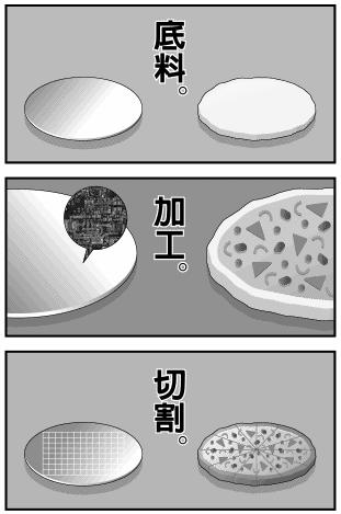
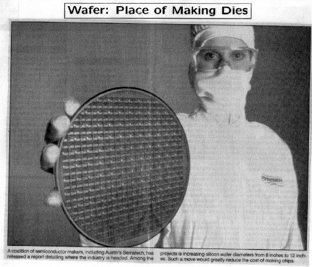
7 IC Fabrication 1-13 Silicon Wafers 1-14

8 Wafer and Dices Source: Sawing a Wafer into Chips 1-16


9 IC and Die 1-17 Chip Packing 1-18

10 Pentium-MMX with PGA Packaging 1-19 Analog v.s. Digital analog waveform digital waveform! Analog system:! Inputs and outputs are represented by continuous values! More close to real-world signals! Often used as interface circuits! Digital system:! Inputs and outputs are represented by discrete values! Easier to handle and design! More tolerable to signal degradation and noise! Binary digital systems form the basis of all hardware design today 1-20
11 Outline! Introductions! Number Base Conversions! Binary Arithmetic! Binary Codes! Binary Elements 1-21 Binary Numbers! Decimal numbers 10 symbols (0, 1, 2,, 9) A10 = a n-1 a n-2 a 1 a 0. a -1 a -2 a -m = Ex: (7392) 10 = 7 x x x x10 0! Binary numbers 2 symbols (0, 1) A 2 = n 1 i= m i ai *10 0 ai n 1 i ai *2 ai i= m = 0,1 9 Ex: ( ) 2 = 1 x x x x x x x2-2 = (26.75)
12 Powers of Two n 2 n n 2 n n 2 n Other Number Bases! In general, a base r (radix r) number system :! Coefficients a n is multiplied by powers of r! Coefficients a n range in value from 0 to r - 1! Example : A r = n 1 i= m ai * r! (4021.2) 5 = 4 x x x x x5-1 = (511.4) 10! (127.4) 8 = 1 x x x x8-1 = (87.5) 10 i 0 a r 1! (B65F) 16 = 11 x x x x16 0 i = (46687)
13 Number Base Conversions (1/2)! Convert (41) 10 to binary 41/2 = 20 remainder = 1 20/2 = 10 = 0 10/2 = 5 = 0 5/2 = 2 = 1 2/2 = 1 = 0 1/2 = 0 = = answer (41) 10 =(101001) 2! Convert (0.6875) 10 to binary x 2 = x 2 = x 2 = x 2 = = answer (0.6875) 10 =(0.1011) Number Base Conversions (2/2)! Convert (153) 10 to octal 153/8 = 19 remainder = 1 19/8 = 2 = 3 2/8 = 0 = = answer (153) 10 =(231) 8! Convert (0.513) 10 to octal x 8 = x 8 = x 8 = x 8 = x 8 = x 8 = = answer (0.513) 10 =( )
14 Fast Conversions! The conversion from and to binary, octal, and hexadecimal is important but much easier! To octal : 3 digits per group ( ) 2 = ( ) ! To hexadecimal : 4 digits per group ( ) 2 = (2C6B.F06) 16 2 C 6 B F 0 6! To binary : inverse process ( ) 8 = ( ) (306.D) 16 = ( ) D 1-27 Octal & Hexadecimal Numbers Base 10 Base2 Base 8 Base16 Base10 Base2 Base 8 Base A B C D E F 1-28
15 Outline! Introductions! Number Base Conversions! Binary Arithmetic! Binary Codes! Binary Elements 1-29 Binary Addition! Binary Addition 0+0=0 sum of 0 with a carry of (45) 0+1=1 sum of 1 with a carry of (39) 1+0=1 sum of 1 with a carry of (84) 1+1=10 sum of 0 with a carry of 1! Binary Addition with carry 1+0+0=01 sum of 1 with a carry of =10 sum of 0 with a carry of =10 sum of 0 with a carry of =11 sum of 1 with a carry of 1 carry bit 1-30
16 Binary Subtraction! Binary Subtraction 0 0 = = = = 1 (borrow 1 from the higher bit) EX : (45) (39) (6) 1-31 Binary Multiplication! Binary Multiplication 0 x 0 = 0 0 x 1 = 0 1 x 0 = 0 1 x 1 = (5) EX : x (5) (25) 1-32
17 Binary Division! Binary Division EX : = Complements! Unsigned binary arithmetic is quite similar to decimal operations! But how about the negative numbers???! Use the complements of positive numbers! Complements can simplify the subtraction operation and logical manipulation! Two types of complements :! Diminished radix complement! Radix complement 1-34
18 Diminished Radix Complement! Given a number N in base r having n digits, the (r-1) s complement of N is defined as (r n -1)-N! The 9 s complement of (546700) 10 is = ! The 9 s complement of (012398) 10 is = ! The 1 s complement of ( ) 2 is ! The 1 s complement of ( ) 2 is bit inverse only!! 1-35 Radix Complement! The r s complement of an n-digit number N in base r is defined as r n -N, for N 0 and 0 for N=0! Equal to its (r-1) s complement added by 1! The 10 s complement of is ! The 10 s complement of is ! The 2 s complement of is ! The 2 s complement of is bit inverse and added with
19 Subtraction with Complements! The subtraction of two n-digit unsigned numbers M N in base r can be done as follows: (1):Add the minuend, M, to the r s complement of the subtrahend, N. M+(r n N)=M N + r n (2):If M N, the sum will produce an end carry, r n, which can be discarded ; what is left is the result M N (3):if M < N, the sum does not produce an end carry and is equal to r n (N M), which is the r s complement of (N M). To obtain the answer in a familiar form, take the r s complement of the sum and placed a negative sign in front 1-37 Examples of Subtraction Given two binary numbers X = and Y = ! X Y (use 2 s complement) 2 s complement of Y = = X Y = X + Y carry is discarded X Y = ! Y X (use 2 s complement) 2 s complement of X = = Y X = Y + X no end carry generated Y X =
20 Signed Binary Numbers! Signed 2 s complement use 2 s comp. Decimal Signed 2 s complement Signed 1 s complement Signed magnitude ! Signed 1 s complement use 1 s comp ! Signed magnitude first digit: sign others: magnitude Arithmetic Addition/Subtraction! The negative numbers are in 2 s complement form! If the sum is negative, it s also in 2 s complement form ! For subtraction, take 2 s complement of the subtrahend (±A) (+B) = (±A) + (-B) (±A) (-B) = (±A) + (+B) 1-40
21 Outline! Introductions! Number Base Conversions! Binary Arithmetic! Binary Codes! Binary Elements 1-41 BCD Code! BCD = Binary Coded Decimal! 4 bits for one digit Decimal symbol 0 1 BCD Digit Ex: (185) 10 = ( ) BCD = ( ) 2! 1010 to 1111 are not used and have no meaning in BCD! Can perform arithmetic operations directly with decimal numbers in digital systems
22 BCD Addition! When the binary sum is equal to or less than 1001 (without a carry), the corresponding BCD digit is correct ! Otherwise, the addition of 6 = (0110) 2 can convert it to the correct digit and also produce the required carry " (0 1001) BCD 10 " (1 0000) BCD 10+6 = 16 = (10000) 2 The addition of 6 can convert to correct digit 1-43 Other Decimal Codes DECIMAL DIGIT Unused bit combinations BCD (8421) weight EXCESS

23 Gray Code Only change one bit when going from one number to the next!! Gray code Decimal equivalent Gray code Decimal equivalent ASCII Character Code 1-46
24 Error-Detecting Code! To detect error in data communication, an extra parity bit is often added! Just count the total number of 1 can decide the status of parity bit! Even parity = 1 " the number of 1 is even (include parity)! Odd parity = 1 " the number of 1 is odd (include parity)! If the received number of 1 does not match the parity bit, an error occurs with even parity with odd parity ASCII A = ASCII T = parity bit 1-47 Outline! Introductions! Number Base Conversions! Binary Arithmetic! Binary Codes! Binary Elements 1-48
25 Binary Elements! Binary cell! Possess two stable states and store one bit of information! Registers! A group of binary cells! A register with n cells can store any discrete quantity of n-bit information! Binary logic! Define the operations with variables that take two discrete values! The operations are implemented by logic gates! Register transfers (to where) and data operations (do what) form the digital systems 1-49 Register Transfer of Information MEMORY UNIT J O H N Memory Register PROCESSOR UNIT 8 cells 8 cells 8 cells 8 cells Processor Register INPUT UNIT KEYBOARD J O H N 8 cells CONTROL Input Register 1-50

26 Logical Operations! Truth tables of logical operations: AND X Y X Y OR X Y X + Y NOT X X ! Logic gates: electronic circuits that perform the corresponding logical operations 1-51 Properties of Logic Gates! Logic gates handle binary signals and also generate binary signals! AND and OR gates may have more than two inputs 1-52
Digital Systems Roberto Muscedere Images 2013 Pearson Education Inc. 1
 Digital Systems Digital systems have such a prominent role in everyday life The digital age The technology around us is ubiquitous, that is we don t even notice it anymore Digital systems are used in:
Digital Systems Overview. Unit 1 Numbering Systems. Why Digital Systems? Levels of Design Abstraction. Dissecting Decimal Numbers
 Unit Numbering Systems Fundamentals of Logic Design EE2369 Prof. Eric MacDonald Fall Semester 2003 Digital Systems Overview Digital Systems are Home PC XBOX or Playstation2 Cell phone Network router Data
14:332:231 DIGITAL LOGIC DESIGN. Why Binary Number System?
 :33:3 DIGITAL LOGIC DESIGN Ivan Marsic, Rutgers University Electrical & Computer Engineering Fall 3 Lecture #: Binary Number System Complement Number Representation X Y Why Binary Number System? Because
MATH Dr. Halimah Alshehri Dr. Halimah Alshehri
 MATH 1101 haalshehri@ksu.edu.sa 1 Introduction To Number Systems First Section: Binary System Second Section: Octal Number System Third Section: Hexadecimal System 2 Binary System 3 Binary System The binary
Logic. Combinational. inputs. outputs. the result. system can
 Digital Electronics Combinational Logic Functions Digital logic circuits can be classified as either combinational or sequential circuits. A combinational circuit is one where the output at any time depends
ENG2410 Digital Design Introduction to Digital Systems. Fall 2017 S. Areibi School of Engineering University of Guelph
 ENG2410 Digital Design Introduction to Digital Systems Fall 2017 S. Areibi School of Engineering University of Guelph Resources Chapter #1, Mano Sections 1.1 Digital Computers 1.2 Number Systems 1.3 Arithmetic
Chapter 1 CSCI
 Chapter 1 CSCI-1510-003 What is a Number? An expression of a numerical quantity A mathematical quantity Many types: Natural Numbers Real Numbers Rational Numbers Irrational Numbers Complex Numbers Etc.
COMBINATIONAL LOGIC FUNCTIONS
 COMBINATIONAL LOGIC FUNCTIONS Digital logic circuits can be classified as either combinational or sequential circuits. A combinational circuit is one where the output at any time depends only on the present
EE260: Digital Design, Spring n Digital Computers. n Number Systems. n Representations. n Conversions. n Arithmetic Operations.
 EE 260: Introduction to Digital Design Number Systems Yao Zheng Department of Electrical Engineering University of Hawaiʻi at Mānoa Overview n Digital Computers n Number Systems n Representations n Conversions
CHAPTER 2 NUMBER SYSTEMS
 CHAPTER 2 NUMBER SYSTEMS The Decimal Number System : We begin our study of the number systems with the familiar decimal number system. The decimal system contains ten unique symbol 0, 1, 2, 3, 4, 5, 6,
Menu. Review of Number Systems EEL3701 EEL3701. Math. Review of number systems >Binary math >Signed number systems
 Menu Review of number systems >Binary math >Signed number systems Look into my... 1 Our decimal (base 10 or radix 10) number system is positional. Ex: 9437 10 = 9x10 3 + 4x10 2 + 3x10 1 + 7x10 0 We have
0 volts. 2 volts. 5 volts
 CS101 Binary Storage Devices and Boolean Logic Now that we have discussed number representation, why do computers use the binary representation and not something we are more familiar with, like decimal?
ENGIN 112 Intro to Electrical and Computer Engineering
 ENGIN 112 Intro to Electrical and Computer Engineering Lecture 3 More Number Systems Overview Hexadecimal numbers Related to binary and octal numbers Conversion between hexadecimal, octal and binary Value
Fundamentals of Digital Design
 Fundamentals of Digital Design Digital Radiation Measurement and Spectroscopy NE/RHP 537 1 Binary Number System The binary numeral system, or base-2 number system, is a numeral system that represents numeric
History & Binary Representation
 History & Binary Representation C. R. da Cunha 1 1 Instituto de Física, Universidade Federal do Rio Grande do Sul, RS 91501-970, Brazil. August 30, 2017 Abstract In this lesson we will review the history
PERFORMANCE METRICS. Mahdi Nazm Bojnordi. CS/ECE 6810: Computer Architecture. Assistant Professor School of Computing University of Utah
 PERFORMANCE METRICS Mahdi Nazm Bojnordi Assistant Professor School of Computing University of Utah CS/ECE 6810: Computer Architecture Overview Announcement Jan. 17 th : Homework 1 release (due on Jan.
of Digital Electronics
 26 Digital Electronics 729 Digital Electronics 26.1 Analog and Digital Signals 26.3 Binary Number System 26.5 Decimal to Binary Conversion 26.7 Octal Number System 26.9 Binary-Coded Decimal Code (BCD Code)
Digital Techniques. Figure 1: Block diagram of digital computer. Processor or Arithmetic logic unit ALU. Control Unit. Storage or memory unit
 Digital Techniques 1. Binary System The digital computer is the best example of a digital system. A main characteristic of digital system is its ability to manipulate discrete elements of information.
Hakim Weatherspoon CS 3410 Computer Science Cornell University
 Hakim Weatherspoon CS 3410 Computer Science Cornell University The slides are the product of many rounds of teaching CS 3410 by Professors Weatherspoon, Bala, Bracy, and Sirer. memory inst 32 register
Logic and Computer Design Fundamentals. Chapter 5 Arithmetic Functions and Circuits
 Logic and Computer Design Fundamentals Chapter 5 Arithmetic Functions and Circuits Arithmetic functions Operate on binary vectors Use the same subfunction in each bit position Can design functional block
CMP 338: Third Class
 CMP 338: Third Class HW 2 solution Conversion between bases The TINY processor Abstraction and separation of concerns Circuit design big picture Moore s law and chip fabrication cost Performance What does
DE58/DC58 LOGIC DESIGN DEC 2014
 Q.2 a. In a base-5 number system, 3 digit representations is used. Find out (i) Number of distinct quantities that can be represented.(ii) Representation of highest decimal number in base-5. Since, r=5
Numbering Systems. Contents: Binary & Decimal. Converting From: B D, D B. Arithmetic operation on Binary.
 Numbering Systems Contents: Binary & Decimal. Converting From: B D, D B. Arithmetic operation on Binary. Addition & Subtraction using Octal & Hexadecimal 2 s Complement, Subtraction Using 2 s Complement.
Unit II Chapter 4:- Digital Logic Contents 4.1 Introduction... 4
 Unit II Chapter 4:- Digital Logic Contents 4.1 Introduction... 4 4.1.1 Signal... 4 4.1.2 Comparison of Analog and Digital Signal... 7 4.2 Number Systems... 7 4.2.1 Decimal Number System... 7 4.2.2 Binary
CMP 334: Seventh Class
 CMP 334: Seventh Class Performance HW 5 solution Averages and weighted averages (review) Amdahl's law Ripple-carry adder circuits Binary addition Half-adder circuits Full-adder circuits Subtraction, negative
CMPE12 - Notes chapter 1. Digital Logic. (Textbook Chapter 3)
") CMPE12 - Notes chapter 1 Digital Logic (Textbook Chapter 3) Transistor: Building Block of Computers Microprocessors contain TONS of transistors Intel Montecito (2005): 1.72 billion Intel Pentium 4 (2000):
CMPE12 - Notes chapter 1 Digital Logic (Textbook Chapter 3) Transistor: Building Block of Computers Microprocessors contain TONS of transistors Intel Montecito (2005): 1.72 billion Intel Pentium 4 (2000):
CprE 281: Digital Logic
 CprE 28: Digital Logic Instructor: Alexander Stoytchev http://www.ece.iastate.edu/~alexs/classes/ Simple Processor CprE 28: Digital Logic Iowa State University, Ames, IA Copyright Alexander Stoytchev Digital
Complement Arithmetic
 Complement Arithmetic Objectives In this lesson, you will learn: How additions and subtractions are performed using the complement representation, What is the Overflow condition, and How to perform arithmetic
NUMBERS AND CODES CHAPTER Numbers
 CHAPTER 2 NUMBERS AND CODES 2.1 Numbers When a number such as 101 is given, it is impossible to determine its numerical value. Some may say it is five. Others may say it is one hundred and one. Could it
Chapter 1 :: From Zero to One
 Chapter 1 :: From Zero to One Digital Design and Computer Architecture David Money Harris and Sarah L. Harris Copyright 2007 Elsevier 1- Chapter 1 :: Topics Background The Game Plan The Art of Managing
CpE358/CS381. Switching Theory and Logical Design. Summer
 Switching Theory and Logical Design - Class Schedule Monday Tuesday Wednesday Thursday Friday May 7 8 9 - Class 2 - Class 2 2 24 - Class 3 25 26 - Class 4 27 28 Quiz Commencement 3 June 2 - Class 5 3 -
Numbers and Arithmetic
 Numbers and Arithmetic See: P&H Chapter 2.4 2.6, 3.2, C.5 C.6 Hakim Weatherspoon CS 3410, Spring 2013 Computer Science Cornell University Big Picture: Building a Processor memory inst register file alu
FYSE410 DIGITAL ELECTRONICS [1] [2] [3] [4] [5] A number system consists of an ordered set of symbols (digits).
![FYSE410 DIGITAL ELECTRONICS [1] [2] [3] [4] [5] A number system consists of an ordered set of symbols (digits).](/thumbs/78/77902386.jpg "FYSE410 DIGITAL ELECTRONICS [1] [2] [3] [4] [5] A number system consists of an ordered set of symbols (digits).") FYSE4 DIGITAL ELECTRONICS Litterature: LECTURE [] [] [4] [5] DIGITAL LOGIC CIRCUIT ANALYSIS & DESIGN Victor P. Nelson, H. Troy Nagle J. David Irwin, ill D. Carroll ISN --4694- DIGITAL DESIGN M. Morris
FYSE4 DIGITAL ELECTRONICS Litterature: LECTURE [] [] [4] [5] DIGITAL LOGIC CIRCUIT ANALYSIS & DESIGN Victor P. Nelson, H. Troy Nagle J. David Irwin, ill D. Carroll ISN --4694- DIGITAL DESIGN M. Morris
Binary addition example worked out
 Binary addition example worked out Some terms are given here Exercise: what are these numbers equivalent to in decimal? The initial carry in is implicitly 0 1 1 1 0 (Carries) 1 0 1 1 (Augend) + 1 1 1 0
Numbers and Arithmetic
 Numbers and Arithmetic See: P&H Chapter 2.4 2.6, 3.2, C.5 C.6 Hakim Weatherspoon CS 3410, Spring 2013 Computer Science Cornell University Big Picture: Building a Processor memory inst register file alu
SAU1A FUNDAMENTALS OF DIGITAL COMPUTERS
 SAU1A FUNDAMENTALS OF DIGITAL COMPUTERS Unit : I - V Unit : I Overview Fundamentals of Computers Characteristics of Computers Computer Language Operating Systems Generation of Computers 2 Definition of
Combinational Logic Design Arithmetic Functions and Circuits
 Combinational Logic Design Arithmetic Functions and Circuits Overview Binary Addition Half Adder Full Adder Ripple Carry Adder Carry Look-ahead Adder Binary Subtraction Binary Subtractor Binary Adder-Subtractor
! Chris Diorio. ! Gaetano Borrielo. ! Carl Ebeling. ! Computing is in its infancy
 Welcome to CSE370 Special Thanks!! Instructor: ruce Hemingway " Ts: ryan Nelson and John Hwang " Tool Specialist: Cory Crawford Lecture Materials:! Chris Diorio! Class web " http://www.cs.washington.edu/education/courses/370/currentqtr/
Digital Systems and Information Part II
 Digital Systems and Information Part II Overview Arithmetic Operations General Remarks Unsigned and Signed Binary Operations Number representation using Decimal Codes BCD code and Seven-Segment Code Text
CSE 241 Digital Systems Spring 2013
 CSE 241 Digital Systems Spring 2013 Instructor: Prof. Kui Ren Department of Computer Science and Engineering Lecture slides modified from many online resources and used solely for the educational purpose.
Conversions between Decimal and Binary
 Conversions between Decimal and Binary Binary to Decimal Technique - use the definition of a number in a positional number system with base 2 - evaluate the definition formula ( the formula ) using decimal
Introduction to Digital Logic Missouri S&T University CPE 2210 Subtractors
 Introduction to Digital Logic Missouri S&T University CPE 2210 Egemen K. Çetinkaya Egemen K. Çetinkaya Department of Electrical & Computer Engineering Missouri University of Science and Technology cetinkayae@mst.edu
Why digital? Overview. Number Systems. Binary to Decimal conversion
 Why digital? Overview It has the following advantages over analog. It can be processed and transmitted efficiently and reliably. It can be stored and retrieved with greater accuracy. Noise level does not
CPE100: Digital Logic Design I
 Chapter 1 Professor Brendan Morris, SEB 3216, brendan.morris@unlv.edu http://www.ee.unlv.edu/~b1morris/cpe100/ CPE100: Digital Logic Design I Section 1004: Dr. Morris From Zero to One Chapter 1 Background:
Class Website:
 ECE 20B, Winter 2003 Introduction to Electrical Engineering, II LECTURE NOTES #5 Instructor: Andrew B. Kahng (lecture) Email: abk@ece.ucsd.edu Telephone: 858-822-4884 office, 858-353-0550 cell Office:
CPE100: Digital Logic Design I
 Chapter 1 Professor Brendan Morris, SEB 3216, brendan.morris@unlv.edu http://www.ee.unlv.edu/~b1morris/cpe100/ CPE100: Digital Logic Design I Section 1004: Dr. Morris From Zero to One Chapter 1 Background:
Mark Redekopp, All rights reserved. Lecture 1 Slides. Intro Number Systems Logic Functions
 Lecture Slides Intro Number Systems Logic Functions EE 0 in Context EE 0 EE 20L Logic Design Fundamentals Logic Design, CAD Tools, Lab tools, Project EE 357 EE 457 Computer Architecture Using the logic
UNIT II COMBINATIONAL CIRCUITS:
 UNIT II COMBINATIONAL CIRCUITS: INTRODUCTION: The digital system consists of two types of circuits, namely (i) (ii) Combinational circuits Sequential circuits Combinational circuit consists of logic gates
Digital Electronics Part 1: Binary Logic
 Digital Electronics Part 1: Binary Logic Electronic devices in your everyday life What makes these products examples of electronic devices? What are some things they have in common? 2 How do electronics
Design of Sequential Circuits
 Design of Sequential Circuits Seven Steps: Construct a state diagram (showing contents of flip flop and inputs with next state) Assign letter variables to each flip flop and each input and output variable
Digital Logic. CS211 Computer Architecture. l Topics. l Transistors (Design & Types) l Logic Gates. l Combinational Circuits.
 l Logic Gates. l Combinational Circuits.") CS211 Computer Architecture Digital Logic l Topics l Transistors (Design & Types) l Logic Gates l Combinational Circuits l K-Maps Figures & Tables borrowed from:! http://www.allaboutcircuits.com/vol_4/index.html!
CS211 Computer Architecture Digital Logic l Topics l Transistors (Design & Types) l Logic Gates l Combinational Circuits l K-Maps Figures & Tables borrowed from:! http://www.allaboutcircuits.com/vol_4/index.html!
XOR - XNOR Gates. The graphic symbol and truth table of XOR gate is shown in the figure.
 XOR - XNOR Gates Lesson Objectives: In addition to AND, OR, NOT, NAND and NOR gates, exclusive-or (XOR) and exclusive-nor (XNOR) gates are also used in the design of digital circuits. These have special
Introduction to Computer Engineering. CS/ECE 252, Fall 2012 Prof. Guri Sohi Computer Sciences Department University of Wisconsin Madison
 Introduction to Computer Engineering CS/ECE 252, Fall 2012 Prof. Guri Sohi Computer Sciences Department University of Wisconsin Madison Chapter 3 Digital Logic Structures Slides based on set prepared by
ELCT201: DIGITAL LOGIC DESIGN
 ELCT2: DIGITL LOGIC DESIGN Dr. Eng. Haitham Omran, haitham.omran@guc.edu.eg Dr. Eng. Wassim lexan, wassim.joseph@guc.edu.eg Lecture Following the slides of Dr. hmed H. Madian ذو الحجة 438 ه Winter 27 2
ECE260: Fundamentals of Computer Engineering
 Data Representation & 2 s Complement James Moscola Dept. of Engineering & Computer Science York College of Pennsylvania Based on Computer Organization and Design, 5th Edition by Patterson & Hennessy Data
Sample Test Paper - I
 Scheme G Sample Test Paper - I Course Name : Computer Engineering Group Marks : 25 Hours: 1 Hrs. Q.1) Attempt any THREE: 09 Marks a) Define i) Propagation delay ii) Fan-in iii) Fan-out b) Convert the following:
Physics 310 Lecture 10 Microprocessors
 Mon. 3/29 Wed. 3/31 Thurs. 4/1 Fri. 4/2 Mon. 4/5 Wed. 4/7 Thurs. 4/8 Fri. 4/9 Mon. 4/12 Wed. 4/14 Thurs. 4/15 Fri. 4/16 Project: Component Shopping Ch 13: Microprocessor Basics Intro to More Ch 13 Review
CHW 261: Logic Design
 CHW 26: Logic Design Instructors: Prof. Hala Zayed Dr. Ahmed Shalaby http://www.bu.edu.eg/staff/halazayed4 http://bu.edu.eg/staff/ahmedshalaby4# Slide Digital Fundamentals Digital Concepts Slide 2 What?
Organisasi dan Arsitektur Komputer L#1: Fundamental Concepts Amil A. Ilham
 Organisasi dan Arsitektur Komputer http://www.unhas.ac.id/amil/stmik2016/arsikom/ L#1: Fundamental Concepts Amil A. Ilham http://www.unhas.ac.id/amil Administrasi Kuliah ADMINISTRASI KULIAH 2 Penilaian
12/31/2010. Digital Operations and Computations Course Notes. 01-Number Systems Text: Unit 1. Overview. What is a Digital System?
 Digital Operations and Computations Course Notes 0-Number Systems Text: Unit Winter 20 Professor H. Louie Department of Electrical & Computer Engineering Seattle University ECEGR/ISSC 20 Digital Operations
PAST EXAM PAPER & MEMO N3 ABOUT THE QUESTION PAPERS:
 EKURHULENI TECH COLLEGE. No. 3 Mogale Square, Krugersdorp. Website: www. ekurhulenitech.co.za Email: info@ekurhulenitech.co.za TEL: 011 040 7343 CELL: 073 770 3028/060 715 4529 PAST EXAM PAPER & MEMO N3
Logic Theory in Designing of Digital Circuit & Microprocessor
 Logic Theory in Designing of Digital Circuit & Microprocessor Prof.Vikram Mahendra Kakade Assistant Professor, Electronics & Telecommunication Engineering Department, Prof Ram Meghe College of Engineering
Systems I: Computer Organization and Architecture
 Systems I: Computer Organization and Architecture Lecture 6 - Combinational Logic Introduction A combinational circuit consists of input variables, logic gates, and output variables. The logic gates accept
0,..., r 1 = digits in radix r number system, that is 0 d i r 1 where m i n 1
 RADIX r NUMBER SYSTEM Let (N) r be a radix r number in a positional weighting number system, then (N) r = d n 1 r n 1 + + d 0 r 0 d 1 r 1 + + d m r m where: r = radix d i = digit at position i, m i n 1
University of Florida EEL 3701 Fall 2014 Dr. Eric. M. Schwartz Department of Electrical & Computer Engineering Wednesday, 15 October 2014
 Page 1/12 Exam 1 May the Schwartz Instructions: be with you! Turn off all cell phones and other noise making devices and put away all electronics Show all work on the front of the test papers Box each
Intro To Digital Logic
 Intro To Digital Logic 1 Announcements... Project 2.2 out But delayed till after the midterm Midterm in a week Covers up to last lecture + next week's homework & lab Nick goes "H-Bomb of Justice" About
Lecture 15: Scaling & Economics
 Lecture 15: Scaling & Economics Outline Scaling Transistors Interconnect Future Challenges Economics 2 Moore s Law Recall that Moore s Law has been driving CMOS [Moore65] Corollary: clock speeds have improved
EECS Components and Design Techniques for Digital Systems. FSMs 9/11/2007
 EECS 150 - Components and Design Techniques for Digital Systems FSMs 9/11/2007 Sarah Bird Electrical Engineering and Computer Sciences University of California, Berkeley Slides borrowed from David Culler
Department of Electrical & Electronics EE-333 DIGITAL SYSTEMS
 Department of Electrical & Electronics EE-333 DIGITAL SYSTEMS 1) Given the two binary numbers X = 1010100 and Y = 1000011, perform the subtraction (a) X -Y and (b) Y - X using 2's complements. a) X = 1010100
MODEL ANSWER SUMMER 17 EXAMINATION Subject Title: Principles of Digital Techniques
 MODEL ANSWER SUMMER 17 EXAMINATION Subject Title: Principles of Digital Techniques Subject Code: Important Instructions to examiners: 1) The answers should be examined by key words and not as word-to-word
Boolean Algebra and Digital Logic 2009, University of Colombo School of Computing
 IT 204 Section 3.0 Boolean Algebra and Digital Logic Boolean Algebra 2 Logic Equations to Truth Tables X = A. B + A. B + AB A B X 0 0 0 0 3 Sum of Products The OR operation performed on the products of
Chapter 7 Logic Circuits
 Chapter 7 Logic Circuits Goal. Advantages of digital technology compared to analog technology. 2. Terminology of Digital Circuits. 3. Convert Numbers between Decimal, Binary and Other forms. 5. Binary
SIR C.R.REDDY COLLEGE OF ENGINEERING ELURU DIGITAL INTEGRATED CIRCUITS (DIC) LABORATORY MANUAL III / IV B.E. (ECE) : I - SEMESTER
 LABORATORY MANUAL III / IV B.E. (ECE) : I - SEMESTER") SIR C.R.REDDY COLLEGE OF ENGINEERING ELURU 534 007 DIGITAL INTEGRATED CIRCUITS (DIC) LABORATORY MANUAL III / IV B.E. (ECE) : I - SEMESTER DEPARTMENT OF ELECTRONICS AND COMMUNICATION ENGINEERING DIGITAL
SIR C.R.REDDY COLLEGE OF ENGINEERING ELURU 534 007 DIGITAL INTEGRATED CIRCUITS (DIC) LABORATORY MANUAL III / IV B.E. (ECE) : I - SEMESTER DEPARTMENT OF ELECTRONICS AND COMMUNICATION ENGINEERING DIGITAL
UNSIGNED BINARY NUMBERS DIGITAL ELECTRONICS SYSTEM DESIGN WHAT ABOUT NEGATIVE NUMBERS? BINARY ADDITION 11/9/2018
 DIGITAL ELECTRONICS SYSTEM DESIGN LL 2018 PROFS. IRIS BAHAR & ROD BERESFORD NOVEMBER 9, 2018 LECTURE 19: BINARY ADDITION, UNSIGNED BINARY NUMBERS For the binary number b n-1 b n-2 b 1 b 0. b -1 b -2 b
3. Complete the following table of equivalent values. Use binary numbers with a sign bit and 7 bits for the value
 EGC22 Digital Logic Fundamental Additional Practice Problems. Complete the following table of equivalent values. Binary. Octal 35.77 33.23.875 29.99 27 9 64 Hexadecimal B.3 D.FD B.4C 2. Calculate the following
MAHARASHTRA STATE BOARD OF TECHNICAL EDUCATION (Autonomous) (ISO/IEC Certified)
 (ISO/IEC Certified)") WINTER 17 EXAMINATION Subject Name: Digital Techniques Model Answer Subject Code: 17333 Important Instructions to examiners: 1) The answers should be examined by key words and not as word-to-word as given
WINTER 17 EXAMINATION Subject Name: Digital Techniques Model Answer Subject Code: 17333 Important Instructions to examiners: 1) The answers should be examined by key words and not as word-to-word as given
on candidate s understanding. 7) For programming language papers, credit may be given to any other program based on equivalent concept.
 For programming language papers, credit may be given to any other program based on equivalent concept.") WINTER 17 EXAMINATION Subject Name: Digital Techniques Model Answer Subject Code: 17333 Important Instructions to examiners: 1) The answers should be examined by key words and not as word-to-word as given
WINTER 17 EXAMINATION Subject Name: Digital Techniques Model Answer Subject Code: 17333 Important Instructions to examiners: 1) The answers should be examined by key words and not as word-to-word as given
Lecture 8: Sequential Multipliers
 Lecture 8: Sequential Multipliers ECE 645 Computer Arithmetic 3/25/08 ECE 645 Computer Arithmetic Lecture Roadmap Sequential Multipliers Unsigned Signed Radix-2 Booth Recoding High-Radix Multiplication
Cs302 Quiz for MID TERM Exam Solved
 Question # 1 of 10 ( Start time: 01:30:33 PM ) Total Marks: 1 Caveman used a number system that has distinct shapes: 4 5 6 7 Question # 2 of 10 ( Start time: 01:31:25 PM ) Total Marks: 1 TTL based devices
SUMMER 18 EXAMINATION Subject Name: Principles of Digital Techniques Model Answer Subject Code:
 Important Instructions to examiners: 1) The answers should be examined by key words and not as word-to-word as given in the model answer scheme. 2) The model answer and the answer written by candidate
Chapter 4. Combinational: Circuits with logic gates whose outputs depend on the present combination of the inputs. elements. Dr.
 Chapter 4 Dr. Panos Nasiopoulos Combinational: Circuits with logic gates whose outputs depend on the present combination of the inputs. Sequential: In addition, they include storage elements Combinational
hexadecimal-to-decimal conversion
 OTHER NUMBER SYSTEMS: octal (digits 0 to 7) group three binary numbers together and represent as base 8 3564 10 = 110 111 101 100 2 = (6X8 3 ) + (7X8 2 ) + (5X8 1 ) + (4X8 0 ) = 6754 8 hexadecimal (digits
ECEN 248: INTRODUCTION TO DIGITAL SYSTEMS DESIGN. Week 2 Dr. Srinivas Shakkottai Dept. of Electrical and Computer Engineering
 ECEN 248: INTRODUCTION TO DIGITAL SYSTEMS DESIGN Week 2 Dr. Srinivas Shakkottai Dept. of Electrical and Computer Engineering Boolean Algebra Boolean Algebra A Boolean algebra is defined with: A set of
Hardware Design I Chap. 4 Representative combinational logic
 Hardware Design I Chap. 4 Representative combinational logic E-mail: shimada@is.naist.jp Already optimized circuits There are many optimized circuits which are well used You can reduce your design workload
Nanotechnology Nanofabrication of Functional Materials. Marin Alexe Max Planck Institute of Microstructure Physics, Halle - Germany
 Nanotechnology Nanofabrication of Functional Materials Marin Alexe Max Planck Institute of Microstructure Physics, Halle - Germany Contents Part I History and background to nanotechnology Nanoworld Nanoelectronics
CHAPTER 7. Exercises 17/ / /2 2 0
 CHAPTER 7 Exercises E7. (a) For the whole part, we have: Quotient Remainders 23/2 /2 5 5/2 2 2/2 0 /2 0 Reading the remainders in reverse order, we obtain: 23 0 = 0 2 For the fractional part we have 2
Four Important Number Systems
 Four Important Number Systems System Why? Remarks Decimal Base 10: (10 fingers) Most used system Binary Base 2: On/Off systems 3-4 times more digits than decimal Octal Base 8: Shorthand notation for working
From Physics to Logic
 From Physics to Logic This course aims to introduce you to the layers of abstraction of modern computer systems. We won t spend much time below the level of bits, bytes, words, and functional units, but
DIGITAL TECHNICS. Dr. Bálint Pődör. Óbuda University, Microelectronics and Technology Institute
 DIGITAL TECHNICS Dr. Bálint Pődör Óbuda University, Microelectronics and Technology Institute 4. LECTURE: COMBINATIONAL LOGIC DESIGN: ARITHMETICS (THROUGH EXAMPLES) 2016/2017 COMBINATIONAL LOGIC DESIGN:
S.Y. Diploma : Sem. III [CO/CM/IF/CD/CW] Digital Techniques s complement 2 s complement 1 s complement
![S.Y. Diploma : Sem. III [CO/CM/IF/CD/CW] Digital Techniques s complement 2 s complement 1 s complement](/thumbs/80/82077570.jpg "S.Y. Diploma : Sem. III [CO/CM/IF/CD/CW] Digital Techniques s complement 2 s complement 1 s complement") S.Y. Diploma : Sem. III [CO/CM/IF/CD/CW] Digital Techniques Time: 3 Hrs.] Prelim Question Paper Solution [Marks : Q.(a) (i) () (2) s COMPLEMENT s COMPLEMENT 2s COMPLEMENT 2s COMPLEMENT + Q.(a) (ii) ()
S.Y. Diploma : Sem. III [CO/CM/IF/CD/CW] Digital Techniques Time: 3 Hrs.] Prelim Question Paper Solution [Marks : Q.(a) (i) () (2) s COMPLEMENT s COMPLEMENT 2s COMPLEMENT 2s COMPLEMENT + Q.(a) (ii) ()
ECE321 Electronics I
 ECE321 Electronics I Lecture 1: Introduction to Digital Electronics Payman Zarkesh-Ha Office: ECE Bldg. 230B Office hours: Tuesday 2:00-3:00PM or by appointment E-mail: payman@ece.unm.edu Slide: 1 Textbook
( c) Give logic symbol, Truth table and circuit diagram for a clocked SR flip-flop. A combinational circuit is defined by the function
 Give logic symbol, Truth table and circuit diagram for a clocked SR flip-flop. A combinational circuit is defined by the function") Question Paper Digital Electronics (EE-204-F) MDU Examination May 2015 1. (a) represent (32)10 in (i) BCD 8421 code (ii) Excess-3 code (iii) ASCII code (b) Design half adder using only NAND gates. ( c)
Question Paper Digital Electronics (EE-204-F) MDU Examination May 2015 1. (a) represent (32)10 in (i) BCD 8421 code (ii) Excess-3 code (iii) ASCII code (b) Design half adder using only NAND gates. ( c)
Combinational Logic. By : Ali Mustafa
 Combinational Logic By : Ali Mustafa Contents Adder Subtractor Multiplier Comparator Decoder Encoder Multiplexer How to Analyze any combinational circuit like this? Analysis Procedure To obtain the output
ENGIN 112 Intro to Electrical and Computer Engineering
 ENGIN 112 Intro to Electrical and Computer Engineering Lecture 2 Number Systems Russell Tessier KEB 309 G tessier@ecs.umass.edu Overview The design of computers It all starts with numbers Building circuits
Computer Architecture, IFE CS and T&CS, 4 th sem. Representation of Integer Numbers in Computer Systems
 Representation of Integer Numbers in Computer Systems Positional Numbering System Additive Systems history but... Roman numerals Positional Systems: r system base (radix) A number value a - digit i digit
LABORATORY MANUAL MICROPROCESSOR AND MICROCONTROLLER
 LABORATORY MANUAL S u b j e c t : MICROPROCESSOR AND MICROCONTROLLER TE (E lectr onics) ( S e m V ) 1 I n d e x Serial No T i tl e P a g e N o M i c r o p r o c e s s o r 8 0 8 5 1 8 Bit Addition by Direct
 vidyarthiplus.com vidyarthiplus.com vidyarthiplus.com ANNA UNIVERSITY- COMBATORE B.E./ B.TECH. DEGREE EXAMINATION - JUNE 2009. ELECTRICAL & ELECTONICS ENGG. - FOURTH SEMESTER DIGITAL LOGIC CIRCUITS PART-A
ECE 340 Lecture 31 : Narrow Base Diode Class Outline:
 ECE 340 Lecture 31 : Narrow Base Diode Class Outline: Narrow-Base Diodes Things you should know when you leave Key Questions What is a narrow-base diode? How does current flow in a narrow-base diode? Quick
ww.padasalai.net
 t w w ADHITHYA TRB- TET COACHING CENTRE KANCHIPURAM SUNDER MATRIC SCHOOL - 9786851468 TEST - 2 COMPUTER SCIENC PG - TRB DATE : 17. 03. 2019 t et t et t t t t UNIT 1 COMPUTER SYSTEM ARCHITECTURE t t t t
Chapter 7. Sequential Circuits Registers, Counters, RAM
 Chapter 7. Sequential Circuits Registers, Counters, RAM Register - a group of binary storage elements suitable for holding binary info A group of FFs constitutes a register Commonly used as temporary storage