Chapter 6 Frequency Response, Bode Plots and Resonance
|
|
|
- Hilda Johnston
- 6 years ago
- Views:
Transcription
1 Chapter 6 Frequency Response, Bode Plots and Resonance Signal Processg is concerned with manipulatg Signals to extract Inormation and to use that ormation to generate other useul Signals
2 Goal. Fundamental Concepts o Fourier Analysis. 2. Filter o a given put consistg o susoidal components usg the ilter s transer unction. 3. Low-pass or High-pass ilter & Transer Functions. 4. Decibels, Logarithmic Frequency Scales, and Bode plots. 5. Understand arious Filters 6. Simple Digital Signal Processg System
3 Fourier Analysis All Real-World Signals are Lear Sums o Susoidal components havg various requencies, amplitudes & phases. τ ω 2π ] s cos [ 2 ) ( t n b t n a a t n n n o ω ω τ ω τ o o t t n dt t n t a cos ) ( 2 + τ ω τ o o t t n dt t n t b s ) ( 2
4 Even Step unction can be analyzed
cos t nωt τ t 2 to + τ bn dt ()s t nωt τ t F(ω) or (t) A kd o Spectrum")
5 Fourier Analysis o Music Time t a n, b n Let ω 2 π/ τ a t a n t b nωt () + ncos ω + ns 2 n 2 to + τ an dt ()cos t nωt τ t 2 to + τ bn dt ()s t nωt τ t F(ω) or (t) A kd o Spectrum Analyzer
6

7 Filters Goal : Reta & Reject the Components Certa Frequency ranges Filters process the Susoid Components o an put signal dierently dependg o the requency o each component. Code as Political Filter!
8 Filters Types Example o Ideal Low Pass ilter
9 Transer Functions Transer unction H( ) o Two-Port Filter : Phasors Output / Phasors Input as a unction o requency H H ( ) ( ) H ( ) : Amplitude Change o Each Frequency Component : Phase Change o Each Frequency Component H ( ) H ( )
10 Filter o Multiple Components. Determe requency & Phasors or each put component. 2. Determe Complex Transer unction or each component. 3. Obta the phasors or each put component by multiplyg the phasors or each put component by transer-unction 4. Convert the phasors or each put components to time unctions. Add these time unctions to produce the put.

11 Experimental Determation o H() - Application o Susoidal Source at ixed requency - Measurement o Output Signal Amplitude, Phase - Procedure is repeated or each requency o terest
12 Active Noise Canceller Noise Reduction Airplane or Car - Passive : Absorber - Active : Canceller Measurement o Signal - Source : Enge Inverse Signal to Loud Speaker - Receiver : Seat Best Cancellation to Passenger

13 Low Pass Filter
14 First-Order Low Pass Filters Total Impedance : Z t Z t Z R + Z C R + R + jωc j2πc I Z t R + j2πc IZ C j2πc I j2πc R + j2πc H ( ) + j2πrc
15 First-Order Low Pass Filters H ( ) + j ( ) B B 2πRC H ( ) + ( ) ( ) 2 B B H arctan
 + j ( ) B B 2πRC I B R 2πL")
16 Low Pass RC & RL Filters H ( ) + j ( ) B B 2πRC I B R 2πL B
17 Decibels H ( ) log H ( ) db 2 Clear Description o Frequency o Certa Range o reqeuncy
 H ( ) 2 ( ) H ( ) H ( ) db db 2 db H +")
18 Cascaded Two-Port Networks H ( ) H ( ) H ( ) H ( ) 2 ( ) H ( ) H ( ) db db 2 db H +
19 Logarithmic Frequency Scales On a logarithmic scale, the variable is multiplied by a given actor or equal crements o length along the axis. Decade : a range o requencies or which the ratio o the highest requency to the lowest is. 2 Number o Decades log Octave : a two-to-one change requency or clear description o low range requency such as 2 to 2 MHz. ( 2 ) ( 2) 2 log Number o Octaves log 2 log
20 Bode Plots Magnitude Decibels versus a logarithmic scale requency. H ( ) log H ( ) db 2 vs log In Low-Pass ilter H ( ) + j ( ) B H ( ) log db + B 2 H ( ) db B Corner requency Breakg Frequency ( ) 3dB at B H db H ( ) 2log db B
21 Phase Bode Plot. A horizontal le at zero or < B /. 2. A slopg le rom zero phase at B / to 9 at B. 3. A horizontal le at 9 or > B.
22 Example o Bode Plot
23 First-Order High-Pass Filters Total Impedance : Z t I Z t Z R + j2πc t Z R + Z C R + R + jωc j2πc IZR RI R R + j2πc H ( ) j2πrc + j2πrc
24 H H ( ) ( ) High Pass RC Filters j + ( ) B j( ) B B 2πRC H + ( ) ( ) 9 o arctan 2 B B

25 High Pass RC & RL Filters B 2πRC j2πl B R 2πL B
26 Bode Plot o High Pass ilter
27 C Summary High Pass Filter Low Pass Filter ( / C ) ( / ) [ ] 2 + / 2 C [ ( ) ] 2 + / / 2 Red Le : Multiplication 2 C ( / C ) ( / ) [ + 2 ] C Red Le shows Band Selection! ( 2 ) c / πrc
28 Band Pass RC Filters with Cascade Network 2 2 ( ) + + ( + r) H L H 2 [ ] 2 L H H 2πR C L L L 2πR C H H r R R H L Low Pass Filter High Pass Filter L L : Pass Band Response o a band-pass ilter
29 Band Reject RC Filters L 2πR C H H H 2πR C L L Not eective combation Use Active ilter! C
30 RC Circuit as Dierentiator oltage oltage across across C : R : I d C [ ] dt R For small RC RC d [ ] dt d dt d dt C d dt >> R RC d dt Dierentiation o Input oltage
31 Dierentiation o Square Wave Leadg Edge Detector
32 RC Circuit as Integrator oltage oltage across across R : C : I C d dt R For Large RC RC d [ ] dt >> C d dt R dt + const RC Integration o Input oltage


33 Mechanical Resonance Electrical Resonance Wd & Bridge Electron & RLC
34 Series Resonance Z s ( ) j2πl + R j 2πC Resonance Frequency 2π LC Quality actor 2π L Q s R 2π CR Total Impedance Z s ( ) R + jq s R L C
35 Impedance Characteristics

36 Filter Case o Series Resonance R Band Pass L High Pass Band Notch C Low Pass
37 Second-Order Low Pass Filter Z s Z s ( ) j2πl + R j 2πC ( ) R + jq s 2π R L 2π CR Q s 2π LC Capacitor Component H ( ) ( s ) ( ) jq + jq s
38 First & Second Order Low Pass Filters
39 Second-Order High Pass Filter Z s ( ) j2πl + R j 2πC Z s ( ) R + jq s 2π R L 2π CR Q s 2π LC Inductor Component H ( ) ( ) s ( ) jq + jq s
40 Bode Plot o Second-Order High Pass Filter
41 Series Resonant Circuit as a Band-Pass Filter + Z s ( ) j2πl + R j 2πC - Z s ( ) R + jq s 2π R L 2π CR Q s 2π LC Resistor Component + jq s ( )
42 Bode Plot o Second-Order Band Pass Filter B H L Qs Q s >> H + B 2 L B 2
43 Series Resonant Circuit as Band-Reject Filter Z Z s LC ( ) R + jq Z L + Z C s j[2πl ] 2πC 2π R L 2π CR Q s 2π LC ( ) ( ) jqs + jq s
44 Bode Plot o Second-Order Band Reject Filter
45 PARALLEL RESONANCE Quality actor Z p Total Impedance ( R) + j2πc j( 2πL) Q R 2π CR p 2π L Z p R + jq p Resonance requency ( ) 2π LC
46 Parallel Resonant Circuit as Band-Pass Filter IR + jq p ( ) B H L Qp
47 Resonance Filter LC o π 2 / ] 2 [2 2 2 L C j j C L j C L LC π π π π + Z Z Z LC R total Z Z Z + RC Q o 2π C L j R total π 2π ) 2 / ( + Z ( ) jq s LC R LC + Z Z Z

48 Photograph o arious Noise Filter


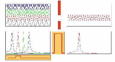
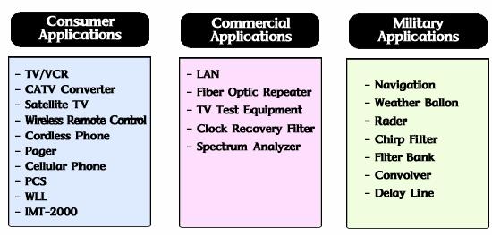
49 SAW Filter SAW : Surace Acoustic Wave o

50 DIGITAL SIGNAL PROCESSING Analog-Digital Converter DSP Digital-Analog Converter ADC : Conversion o Signals rom Analog to Digital Form s > 2 : Samplg Rate (requency) H I a signal contas no components with requencies higher than H, the signal can be exactly reconstructed rom its samples, provided that the samplg rate s is selected to be more than twice H.
51 Example o ADC (3bit ADC) Samplg Error T s k N 2 Quantization Error
52 Digital Low Pass Filter KCL at Top Node y ( t) R x( t) + C dy( t) dt y () t with y x dy( t) t) + τ dt τ RC ( ( t) τ T a + τ T ( n) ay( n ) + ( a) x( n) dy δy( t) y( n) y( n ) dt δ t T
53 Application o Digital Low Pass ilter to Step Signal Step Signal (Red Le) o : Digitized Signal x : Filtered Signal Step unction must be smoothed by Low Pass ilter, leadg to Constant value y τ T a + τ T ( n) ay( n ) + ( a)() x n

54 Signal with Typical Noise

55 Filtered Signal
Fourier Analysis, Low Pass Filters, Decibels
 Lecture 8 Furier Analysis, Lw Pass Filters, Decibels ELECTRICAL ENGINEERING: PRINCIPLES AND APPLICATIONS, Furth Edit, by Allan R. Hambley, 008 Pearsn Educat, Inc. Chapter 6 Frequency Respnse, Bde Plts,
EE221 Circuits II. Chapter 14 Frequency Response
 EE22 Circuits II Chapter 4 Frequency Response Frequency Response Chapter 4 4. Introduction 4.2 Transfer Function 4.3 Bode Plots 4.4 Series Resonance 4.5 Parallel Resonance 4.6 Passive Filters 4.7 Active
EE221 Circuits II. Chapter 14 Frequency Response
 EE22 Circuits II Chapter 4 Frequency Response Frequency Response Chapter 4 4. Introduction 4.2 Transfer Function 4.3 Bode Plots 4.4 Series Resonance 4.5 Parallel Resonance 4.6 Passive Filters 4.7 Active
Sinusoidal Steady-State Analysis
 Chapter 4 Sinusoidal Steady-State Analysis In this unit, we consider circuits in which the sources are sinusoidal in nature. The review section of this unit covers most of section 9.1 9.9 of the text.
Electronics Lecture 8 AC circuit analysis using phasors
 Electronics Lecture 8 A circuit analysis usg phasors 8. Introduction The preious lecture discussed the transient response of an circuit to a step oltage by switchg a battery. This lecture will estigate
Lecture 4: R-L-C Circuits and Resonant Circuits
 Lecture 4: R-L-C Circuits and Resonant Circuits RLC series circuit: What's V R? Simplest way to solve for V is to use voltage divider equation in complex notation: V X L X C V R = in R R + X C + X L L
Philadelphia University Faculty of Engineering Communication and Electronics Engineering
 Module: Electronics II Module Number: 6503 Philadelphia University Faculty o Engineering Communication and Electronics Engineering Ampliier Circuits-II BJT and FET Frequency Response Characteristics: -
Designing Information Devices and Systems II Fall 2018 Elad Alon and Miki Lustig Discussion 5A
 EECS 6B Designing Information Devices and Systems II Fall 208 Elad Alon and Miki Lustig Discussion 5A Transfer Function When we write the transfer function of an arbitrary circuit, it always takes the
To find the step response of an RC circuit
 To find the step response of an RC circuit v( t) v( ) [ v( t) v( )] e tt The time constant = RC The final capacitor voltage v() The initial capacitor voltage v(t ) To find the step response of an RL circuit
1 Phasors and Alternating Currents
 Physics 4 Chapter : Alternating Current 0/5 Phasors and Alternating Currents alternating current: current that varies sinusoidally with time ac source: any device that supplies a sinusoidally varying potential
R-L-C Circuits and Resonant Circuits
 P517/617 Lec4, P1 R-L-C Circuits and Resonant Circuits Consider the following RLC series circuit What's R? Simplest way to solve for is to use voltage divider equation in complex notation. X L X C in 0
) t 0(q+ t ) dt n t( t) dt ( rre i dq t 0 u = = t l C t) t) a i( ( q tric c le E
 t 0(q+ t ) dt n t( t) dt ( rre i dq t 0 u = = t l C t) t) a i( ( q tric c le E") EE70 eview Electrical Current i ( t ) dq ( t ) dt t q ( t ) i ( t ) dt + t 0 q ( t 0 ) Circuit Elements An electrical circuit consists o circuit elements such as voltage sources, resistances, inductances
EE70 eview Electrical Current i ( t ) dq ( t ) dt t q ( t ) i ( t ) dt + t 0 q ( t 0 ) Circuit Elements An electrical circuit consists o circuit elements such as voltage sources, resistances, inductances
Dr. Kasra Etemadi February 27, 2007
 Dr. Kasra Eteadi February 7, 7 Chapter 4:Transients Chapter 5: Sinusidal Surces Chapter 6: nnsinusidal surces Furier Trasr Transer Functin Filters Lwpass Filters Highpass Filters andpass Filters Surce
BIOEN 302, Section 3: AC electronics
 BIOEN 3, Section 3: AC electronics For this section, you will need to have very present the basics of complex number calculus (see Section for a brief overview) and EE5 s section on phasors.. Representation
Alternating Current Circuits. Home Work Solutions
 Chapter 21 Alternating Current Circuits. Home Work s 21.1 Problem 21.11 What is the time constant of the circuit in Figure (21.19). 10 Ω 10 Ω 5.0 Ω 2.0µF 2.0µF 2.0µF 3.0µF Figure 21.19: Given: The circuit
EE 40: Introduction to Microelectronic Circuits Spring 2008: Midterm 2
 EE 4: Introduction to Microelectronic Circuits Spring 8: Midterm Venkat Anantharam 3/9/8 Total Time Allotted : min Total Points:. This is a closed book exam. However, you are allowed to bring two pages
Today. 1/25/11 Physics 262 Lecture 2 Filters. Active Components and Filters. Homework. Lab 2 this week
 /5/ Physics 6 Lecture Filters Today Basics: Analog versus Digital; Passive versus Active Basic concepts and types of filters Passband, Stopband, Cut-off, Slope, Knee, Decibels, and Bode plots Active Components
Single-Time-Constant (STC) Circuits This lecture is given as a background that will be needed to determine the frequency response of the amplifiers.
 Circuits This lecture is given as a background that will be needed to determine the frequency response of the amplifiers.") Single-Time-Constant (STC) Circuits This lecture is given as a background that will be needed to determine the frequency response of the amplifiers. Objectives To analyze and understand STC circuits with
Single-Time-Constant (STC) Circuits This lecture is given as a background that will be needed to determine the frequency response of the amplifiers. Objectives To analyze and understand STC circuits with
Frequency Response. Re ve jφ e jωt ( ) where v is the amplitude and φ is the phase of the sinusoidal signal v(t). ve jφ
 where v is the amplitude and φ is the phase of the sinusoidal signal v(t). ve jφ") 27 Frequency Response Before starting, review phasor analysis, Bode plots... Key concept: small-signal models for amplifiers are linear and therefore, cosines and sines are solutions of the linear differential
27 Frequency Response Before starting, review phasor analysis, Bode plots... Key concept: small-signal models for amplifiers are linear and therefore, cosines and sines are solutions of the linear differential
Source-Free RC Circuit
 First Order Circuits Source-Free RC Circuit Initial charge on capacitor q = Cv(0) so that voltage at time 0 is v(0). What is v(t)? Prof Carruthers (ECE @ BU) EK307 Notes Summer 2018 150 / 264 First Order
Electronics. Basics & Applications. group talk Daniel Biesinger
 Electronics Basics & Applications group talk 23.7.2010 by Daniel Biesinger 1 2 Contents Contents Basics Simple applications Equivalent circuit Impedance & Reactance More advanced applications - RC circuits
Decibels, Filters, and Bode Plots
 23 db Decibels, Filters, and Bode Plots 23. LOGAITHMS The use o logarithms in industry is so extensive that a clear understanding o their purpose and use is an absolute necessity. At irst exposure, logarithms
EECE 2510 Circuits and Signals, Biomedical Applications Final Exam Section 3. Name:
 EECE 2510 Circuits and Signals, Biomedical Applications Final Exam Section 3 Instructions: Closed book, closed notes; Computers and cell phones are not allowed Scientific calculators are allowed Complete
Network Graphs and Tellegen s Theorem
 Networ Graphs and Tellegen s Theorem The concepts of a graph Cut sets and Kirchhoff s current laws Loops and Kirchhoff s voltage laws Tellegen s Theorem The concepts of a graph The analysis of a complex
Dynamic circuits: Frequency domain analysis
 Electronic Circuits 1 Dynamic circuits: Contents Free oscillation and natural frequency Transfer functions Frequency response Bode plots 1 System behaviour: overview 2 System behaviour : review solution
EE40 Lec 13. Prof. Nathan Cheung 10/13/2009. Reading: Hambley Chapter Chapter 14.10,14.5
 EE4 Lec 13 Filter and eonance Pro. Nathan Cheung 1/13/9 eading: Hambley Chapter 6.6-6.8 Chapter 14.1,14.5 Slide 1 Common Filter Traner Function v. Freq H ( ) H( ) Low Pa High Pa Frequency H ( ) H ( ) Frequency
Assessment Schedule 2015 Physics: Demonstrate understanding of electrical systems (91526)
") NCEA Level 3 Physics (91526) 2015 page 1 of 6 Assessment Schedule 2015 Physics: Demonstrate understanding of electrical systems (91526) Evidence Q Evidence Achievement Achievement with Merit Achievement
NCEA Level 3 Physics (91526) 2015 page 1 of 6 Assessment Schedule 2015 Physics: Demonstrate understanding of electrical systems (91526) Evidence Q Evidence Achievement Achievement with Merit Achievement
CHAPTER.6 :TRANSISTOR FREQUENCY RESPONSE
 CHAPTER.6 :TRANSISTOR FREQUENCY RESPONSE To understand Decibels, log scale, general frequency considerations of an amplifier. low frequency analysis - Bode plot low frequency response BJT amplifier Miller
Sophomore Physics Laboratory (PH005/105)
") CALIFORNIA INSTITUTE OF TECHNOLOGY PHYSICS MATHEMATICS AND ASTRONOMY DIVISION Sophomore Physics Laboratory (PH5/15) Analog Electronics Active Filters Copyright c Virgínio de Oliveira Sannibale, 23 (Revision
CALIFORNIA INSTITUTE OF TECHNOLOGY PHYSICS MATHEMATICS AND ASTRONOMY DIVISION Sophomore Physics Laboratory (PH5/15) Analog Electronics Active Filters Copyright c Virgínio de Oliveira Sannibale, 23 (Revision
EE40 Midterm Review Prof. Nathan Cheung
 EE40 Midterm Review Prof. Nathan Cheung 10/29/2009 Slide 1 I feel I know the topics but I cannot solve the problems Now what? Slide 2 R L C Properties Slide 3 Ideal Voltage Source *Current depends d on
OPERATIONAL AMPLIFIER APPLICATIONS
 OPERATIONAL AMPLIFIER APPLICATIONS 2.1 The Ideal Op Amp (Chapter 2.1) Amplifier Applications 2.2 The Inverting Configuration (Chapter 2.2) 2.3 The Non-inverting Configuration (Chapter 2.3) 2.4 Difference
Time Varying Circuit Analysis
 MAS.836 Sensor Systems for Interactive Environments th Distributed: Tuesday February 16, 2010 Due: Tuesday February 23, 2010 Problem Set # 2 Time Varying Circuit Analysis The purpose of this problem set
Decibels, Filters, and Bode Plots
 Decibels, Filters, and Bode Plots 2 Objectives Develop conidence in the use o logarithms and decibels in the description o power and voltage levels. Become amiliar with the requency response o high- and
Sinusoidal Response of RLC Circuits
 Sinusoidal Response of RLC Circuits Series RL circuit Series RC circuit Series RLC circuit Parallel RL circuit Parallel RC circuit R-L Series Circuit R-L Series Circuit R-L Series Circuit Instantaneous
Chapter 8: Converter Transfer Functions
 Chapter 8. Converter Transer Functions 8.1. Review o Bode plots 8.1.1. Single pole response 8.1.2. Single zero response 8.1.3. Right hal-plane zero 8.1.4. Frequency inversion 8.1.5. Combinations 8.1.6.
Filters and Tuned Amplifiers
 Filters and Tuned Amplifiers Essential building block in many systems, particularly in communication and instrumentation systems Typically implemented in one of three technologies: passive LC filters,
Speaker: Arthur Williams Chief Scientist Telebyte Inc. Thursday November 20 th 2008 INTRODUCTION TO ACTIVE AND PASSIVE ANALOG
 INTRODUCTION TO ACTIVE AND PASSIVE ANALOG FILTER DESIGN INCLUDING SOME INTERESTING AND UNIQUE CONFIGURATIONS Speaker: Arthur Williams Chief Scientist Telebyte Inc. Thursday November 20 th 2008 TOPICS Introduction
Midterm 1 Announcements
 Midterm Announcements eiew session: 5-8pm TONIGHT 77 Cory Midterm : :30-pm on Tuesday, July Dwelle 45. Material coered HW-3 Attend only your second lab slot this wee EE40 Summer 005: Lecture 9 Instructor:
Lecture 9 Time Domain vs. Frequency Domain
 . Topics covered Lecture 9 Time Domain vs. Frequency Domain (a) AC power in the time domain (b) AC power in the frequency domain (c) Reactive power (d) Maximum power transfer in AC circuits (e) Frequency
EECE 2150 Circuits and Signals Final Exam Fall 2016 Dec 16
 EECE 2150 Circuits and Signals Final Exam Fall 2016 Dec 16 Instructions: Write your name and section number on all pages Closed book, closed notes; Computers and cell phones are not allowed You can use
EE40 Homework #6. Due Oct 15 (Thursday), 12:00 noon in Cory 240
, 12:00 noon in Cory 240") Fall 2009 EE40 Homework #6 Due Oct 15 (Thursday), 12:00 noon in Cory 240 Reading Assignments Chapter 5 of Hambley textbook. Section 5.7 on Three-Phase circuit is optional Sections 6.1-6.5 of Hambley textbook
Fall 2009 EE40 Homework #6 Due Oct 15 (Thursday), 12:00 noon in Cory 240 Reading Assignments Chapter 5 of Hambley textbook. Section 5.7 on Three-Phase circuit is optional Sections 6.1-6.5 of Hambley textbook
Asymptote. 2 Problems 2 Methods
 Asymptote Problems Methods Problems Assume we have the ollowing transer unction which has a zero at =, a pole at = and a pole at =. We are going to look at two problems: problem is where >> and problem
Lecture #3. Review: Power
 Lecture #3 OUTLINE Power calculations Circuit elements Voltage and current sources Electrical resistance (Ohm s law) Kirchhoff s laws Reading Chapter 2 Lecture 3, Slide 1 Review: Power If an element is
Signals, Instruments, and Systems W5. Introduction to Signal Processing Sampling, Reconstruction, and Filters
 Signals, Instruments, and Systems W5 Introduction to Signal Processing Sampling, Reconstruction, and Filters Acknowledgments Recapitulation of Key Concepts from the Last Lecture Dirac delta function (
(amperes) = (coulombs) (3.1) (seconds) Time varying current. (volts) =
 = (coulombs) (3.1) (seconds) Time varying current. (volts) =") 3 Electrical Circuits 3. Basic Concepts Electric charge coulomb of negative change contains 624 0 8 electrons. Current ampere is a steady flow of coulomb of change pass a given point in a conductor in
3 Electrical Circuits 3. Basic Concepts Electric charge coulomb of negative change contains 624 0 8 electrons. Current ampere is a steady flow of coulomb of change pass a given point in a conductor in
Handout 11: AC circuit. AC generator
 Handout : AC circuit AC generator Figure compares the voltage across the directcurrent (DC) generator and that across the alternatingcurrent (AC) generator For DC generator, the voltage is constant For
Chapter 33. Alternating Current Circuits
 Chapter 33 Alternating Current Circuits 1 Capacitor Resistor + Q = C V = I R R I + + Inductance d I Vab = L dt AC power source The AC power source provides an alternative voltage, Notation - Lower case
Assessment Schedule 2016 Physics: Demonstrate understanding electrical systems (91526)
") NCEA evel 3 Physics (91526) 2016 page 1 of 5 Assessment Schedule 2016 Physics: Demonstrate understanding electrical systems (91526) Evidence Statement NØ N1 N 2 A 3 A 4 M 5 M 6 E 7 E 8 0 1A 2A 3A 4A or
NCEA evel 3 Physics (91526) 2016 page 1 of 5 Assessment Schedule 2016 Physics: Demonstrate understanding electrical systems (91526) Evidence Statement NØ N1 N 2 A 3 A 4 M 5 M 6 E 7 E 8 0 1A 2A 3A 4A or
Homework Assignment 08
 Homework Assignment 08 Question 1 (Short Takes) Two points each unless otherwise indicated. 1. Give one phrase/sentence that describes the primary advantage of an active load. Answer: Large effective resistance
Frequency domain analysis of linear circuits using synchronous detection
 Frequency doma analysis of lear circuits usg synchronous detection Introduction In this experiment, we will study the behavior of simple electronic circuits whose response varies as a function of frequency.
Frequency response. Pavel Máša - XE31EO2. XE31EO2 Lecture11. Pavel Máša - XE31EO2 - Frequency response
 Frequency response XE3EO2 Lecture Pavel Máša - Frequency response INTRODUCTION Frequency response describe frequency dependence of output to input voltage magnitude ratio and its phase shift as a function
H(s) = 2(s+10)(s+100) (s+1)(s+1000)
 = 2(s+10)(s+100) (s+1)(s+1000)") Problem 1 Consider the following transfer function H(s) = 2(s10)(s100) (s1)(s1000) (a) Draw the asymptotic magnitude Bode plot for H(s). Solution: The transfer function is not in standard form to sketch
Problem 1 Consider the following transfer function H(s) = 2(s10)(s100) (s1)(s1000) (a) Draw the asymptotic magnitude Bode plot for H(s). Solution: The transfer function is not in standard form to sketch
QUESTION BANK SUBJECT: NETWORK ANALYSIS (10ES34)
") QUESTION BANK SUBJECT: NETWORK ANALYSIS (10ES34) NOTE: FOR NUMERICAL PROBLEMS FOR ALL UNITS EXCEPT UNIT 5 REFER THE E-BOOK ENGINEERING CIRCUIT ANALYSIS, 7 th EDITION HAYT AND KIMMERLY. PAGE NUMBERS OF
QUESTION BANK SUBJECT: NETWORK ANALYSIS (10ES34) NOTE: FOR NUMERICAL PROBLEMS FOR ALL UNITS EXCEPT UNIT 5 REFER THE E-BOOK ENGINEERING CIRCUIT ANALYSIS, 7 th EDITION HAYT AND KIMMERLY. PAGE NUMBERS OF
P441 Analytical Mechanics - I. RLC Circuits. c Alex R. Dzierba. In this note we discuss electrical oscillating circuits: undamped, damped and driven.
 Lecture 10 Monday - September 19, 005 Written or last updated: September 19, 005 P441 Analytical Mechanics - I RLC Circuits c Alex R. Dzierba Introduction In this note we discuss electrical oscillating
AC Circuits. The Capacitor
 The Capacitor Two conductors in close proximity (and electrically isolated from one another) form a capacitor. An electric field is produced by charge differences between the conductors. The capacitance
AC Circuit Analysis and Measurement Lab Assignment 8
 Electric Circuit Lab Assignments elcirc_lab87.fm - 1 AC Circuit Analysis and Measurement Lab Assignment 8 Introduction When analyzing an electric circuit that contains reactive components, inductors and
ECE 2100 Lecture notes Wed, 1/22/03
 HW #4, due, /24 Ch : 34, 37, 43 ECE 0 Lecture notes Wed, /22/03 Exercises: 2., 2.2, 2.4, 2.5 Stu or hints etc., see lecture notes or, /7 Problem Sessions: W, :50-2:40 am, WBB 22 (tall brick geology building),
Low Pass Filters, Sinusoidal Input, and Steady State Output
 Low Pass Filters, Sinusoidal Input, and Steady State Output Jaimie Stephens and Michael Bruce 5-2-4 Abstract Discussion of applications and behaviors of low pass filters when presented with a steady-state
Sinusoidal Steady-State Analysis
 Sinusoidal Steady-State Analysis Mauro Forti October 27, 2018 Constitutive Relations in the Frequency Domain Consider a network with independent voltage and current sources at the same angular frequency
Phasors: Impedance and Circuit Anlysis. Phasors
 Phasors: Impedance and Circuit Anlysis Lecture 6, 0/07/05 OUTLINE Phasor ReCap Capacitor/Inductor Example Arithmetic with Complex Numbers Complex Impedance Circuit Analysis with Complex Impedance Phasor
Response of Second-Order Systems
 Unit 3 Response of SecondOrder Systems In this unit, we consider the natural and step responses of simple series and parallel circuits containing inductors, capacitors and resistors. The equations which
EE292: Fundamentals of ECE
 EE292: Fundamentals of ECE Fall 2012 TTh 10:00-11:15 SEB 1242 Lecture 20 121101 http://www.ee.unlv.edu/~b1morris/ee292/ 2 Outline Chapters 1-3 Circuit Analysis Techniques Chapter 10 Diodes Ideal Model
EM Oscillations. David J. Starling Penn State Hazleton PHYS 212
 I ve got an oscillating fan at my house. The fan goes back and forth. It looks like the fan is saying No. So I like to ask it questions that a fan would say no to. Do you keep my hair in place? Do you
Signals & Linear Systems Analysis Chapter 2&3, Part II
 Signals & Linear Systems Analysis Chapter &3, Part II Dr. Yun Q. Shi Dept o Electrical & Computer Engr. New Jersey Institute o echnology Email: shi@njit.edu et used or the course:
Electric Circuit Theory
 Electric Circuit Theory Nam Ki Min nkmin@korea.ac.kr 010-9419-2320 Chapter 8 Natural and Step Responses of RLC Circuits Nam Ki Min nkmin@korea.ac.kr 010-9419-2320 8.1 Introduction to the Natural Response
Some of the different forms of a signal, obtained by transformations, are shown in the figure. jwt e z. jwt z e
 Transform methods Some of the different forms of a signal, obtained by transformations, are shown in the figure. X(s) X(t) L - L F - F jw s s jw X(jw) X*(t) F - F X*(jw) jwt e z jwt z e X(nT) Z - Z X(z)
I. Impedance of an R-L circuit.
 I. Impedance of an R-L circuit. [For inductor in an AC Circuit, see Chapter 31, pg. 1024] Consider the R-L circuit shown in Figure: 1. A current i(t) = I cos(ωt) is driven across the circuit using an AC
EXPERIMENT 07 TO STUDY DC RC CIRCUIT AND TRANSIENT PHENOMENA
 EXPERIMENT 07 TO STUDY DC RC CIRCUIT AND TRANSIENT PHENOMENA DISCUSSION The capacitor is a element which stores electric energy by charging the charge on it. Bear in mind that the charge on a capacitor
2.1 The electric field outside a charged sphere is the same as for a point source, E(r) =
 =") Chapter Exercises. The electric field outside a charged sphere is the same as for a point source, E(r) Q 4πɛ 0 r, where Q is the charge on the inner surface of radius a. The potential drop is the integral
Chapter Exercises. The electric field outside a charged sphere is the same as for a point source, E(r) Q 4πɛ 0 r, where Q is the charge on the inner surface of radius a. The potential drop is the integral
Circuit Analysis. by John M. Santiago, Jr., PhD FOR. Professor of Electrical and Systems Engineering, Colonel (Ret) USAF. A Wiley Brand FOR-
 USAF. A Wiley Brand FOR-") Circuit Analysis FOR A Wiley Brand by John M. Santiago, Jr., PhD Professor of Electrical and Systems Engineering, Colonel (Ret) USAF FOR- A Wiley Brand Table of Contents. ' : '" '! " ' ' '... ',. 1 Introduction
Circuit Analysis FOR A Wiley Brand by John M. Santiago, Jr., PhD Professor of Electrical and Systems Engineering, Colonel (Ret) USAF FOR- A Wiley Brand Table of Contents. ' : '" '! " ' ' '... ',. 1 Introduction
Sinusoidal Steady State Analysis (AC Analysis) Part I
 Part I") Sinusoidal Steady State Analysis (AC Analysis) Part I Amin Electronics and Electrical Communications Engineering Department (EECE) Cairo University elc.n102.eng@gmail.com http://scholar.cu.edu.eg/refky/
Sinusoidal Steady State Analysis (AC Analysis) Part I Amin Electronics and Electrical Communications Engineering Department (EECE) Cairo University elc.n102.eng@gmail.com http://scholar.cu.edu.eg/refky/
Department of Mechanical and Aerospace Engineering. MAE334 - Introduction to Instrumentation and Computers. Final Examination.
 Name: Number: Department of Mechanical and Aerospace Engineering MAE334 - Introduction to Instrumentation and Computers Final Examination December 12, 2003 Closed Book and Notes 1. Be sure to fill in your
Patrick F. Dunn 107 Hessert Laboratory Department of Aerospace and Mechanical Engineering University of Notre Dame Notre Dame, IN 46556
 Learning Objectives to Accompany MEASUREMENT AND DATA ANALYSIS FOR ENGINEERING AND SCIENCE Second Edition, Taylor and Francis/CRC Press, c 2010 ISBN: 9781439825686 Patrick F. Dunn pdunn@nd.edu 107 Hessert
Spectral Dissipation Term for Wave Forecast Models, Experimental Study
 pectral Dissipation Term or Wave Forecast Models, Experimental tudy Alexander Baban, Ian Young, Richard Manasseh and Eric chultz wburne University o Technology, Melbourne, Australia CIRO, Melbourne, Australia
Supplemental Notes on Complex Numbers, Complex Impedance, RLC Circuits, and Resonance
 Supplemental Notes on Complex Numbers, Complex Impedance, RLC Circuits, and Resonance Complex numbers Complex numbers are expressions of the form z = a + ib, where both a and b are real numbers, and i
EE292: Fundamentals of ECE
 EE292: Fundamentals of ECE Fall 2012 TTh 10:00-11:15 SEB 1242 Lecture 18 121025 http://www.ee.unlv.edu/~b1morris/ee292/ 2 Outline Review RMS Values Complex Numbers Phasors Complex Impedance Circuit Analysis
Master Degree in Electronic Engineering. Analog and Telecommunication Electronics course Prof. Del Corso Dante A.Y Switched Capacitor
 Master Degree in Electronic Engineering TOP-UIC Torino-Chicago Double Degree Project Analog and Telecommunication Electronics course Prof. Del Corso Dante A.Y. 2013-2014 Switched Capacitor Working Principles
RLC Series Circuit. We can define effective resistances for capacitors and inductors: 1 = Capacitive reactance:
 RLC Series Circuit In this exercise you will investigate the effects of changing inductance, capacitance, resistance, and frequency on an RLC series AC circuit. We can define effective resistances for
RLC Circuits. 1 Introduction. 1.1 Undriven Systems. 1.2 Driven Systems
 RLC Circuits Equipment: Capstone, 850 interface, RLC circuit board, 4 leads (91 cm), 3 voltage sensors, Fluke mulitmeter, and BNC connector on one end and banana plugs on the other Reading: Review AC circuits
Advanced Analog Building Blocks. Prof. Dr. Peter Fischer, Dr. Wei Shen, Dr. Albert Comerma, Dr. Johannes Schemmel, etc
 Advanced Analog Building Blocks Prof. Dr. Peter Fischer, Dr. Wei Shen, Dr. Albert Comerma, Dr. Johannes Schemmel, etc 1 Topics 1. S domain and Laplace Transform Zeros and Poles 2. Basic and Advanced current
ECE Spring 2015 Final Exam
 ECE 20100 Spring 2015 Final Exam May 7, 2015 Section (circle below) Jung (1:30) 0001 Qi (12:30) 0002 Peleato (9:30) 0004 Allen (10:30) 0005 Zhu (4:30) 0006 Name PUID Instructions 1. DO NOT START UNTIL
Design Engineering MEng EXAMINATIONS 2016
 IMPERIAL COLLEGE LONDON Design Engineering MEng EXAMINATIONS 2016 For Internal Students of the Imperial College of Science, Technology and Medicine This paper is also taken for the relevant examination
EE100Su08 Lecture #9 (July 16 th 2008)
") EE100Su08 Lecture #9 (July 16 th 2008) Outline HW #1s and Midterm #1 returned today Midterm #1 notes HW #1 and Midterm #1 regrade deadline: Wednesday, July 23 rd 2008, 5:00 pm PST. Procedure: HW #1: Bart
EE100Su08 Lecture #9 (July 16 th 2008) Outline HW #1s and Midterm #1 returned today Midterm #1 notes HW #1 and Midterm #1 regrade deadline: Wednesday, July 23 rd 2008, 5:00 pm PST. Procedure: HW #1: Bart
Physics 405/505 Digital Electronics Techniques. University of Arizona Spring 2006 Prof. Erich W. Varnes
 Physics 405/505 Digital Electronics Techniques University of Arizona Spring 2006 Prof. Erich W. Varnes Administrative Matters Contacting me I will hold office hours on Tuesday from 1-3 pm Room 420K in
PY3107 Experimental Physics II
 PY3107 Experimental Physics II ock-in Amplifiers MP aughan and F Peters Related Experiments ock-in ab ignal processing and phase sensitive detection using a lock-in amplifier The problem The signal to
EECE 2150 Circuits and Signals, Biomedical Applications Final Exam Section 3
 EECE 2150 Circuits and Signals, Biomedical Applications Final Exam Section 3 Instructions: Closed book, closed notes; Computers and cell phones are not allowed You may use the equation sheet provided but
Electrical Circuits Lab Series RC Circuit Phasor Diagram
 Electrical Circuits Lab. 0903219 Series RC Circuit Phasor Diagram - Simple steps to draw phasor diagram of a series RC circuit without memorizing: * Start with the quantity (voltage or current) that is
IFB270 Advanced Electronic Circuits
 IFB270 Advanced Electronic Circuits Chapter 0: Ampliier requency response Pro. Manar Mohaisen Department o EEC Engineering Review o the Precedent Lecture Reviewed o the JFET and MOSFET Explained and analyzed
MODULE I. Transient Response:
 Transient Response: MODULE I The Transient Response (also known as the Natural Response) is the way the circuit responds to energies stored in storage elements, such as capacitors and inductors. If a capacitor
Definitions. Decade: A ten-to-one range of frequency. On a log scale, each 10X change in frequency requires the same distance on the scale.
 Circuits II EECS 3220 Lecture notes on making Bode plots Definitions Network Transfer Function: The function H s Xout s X in s where X out represents the voltage or current response of the network to X
Electromagnetic Oscillations and Alternating Current. 1. Electromagnetic oscillations and LC circuit 2. Alternating Current 3.
 Electromagnetic Oscillations and Alternating Current 1. Electromagnetic oscillations and LC circuit 2. Alternating Current 3. RLC circuit in AC 1 RL and RC circuits RL RC Charging Discharging I = emf R
Basics of Network Theory (Part-I)
") Basics of Network Theory (PartI). A square waveform as shown in figure is applied across mh ideal inductor. The current through the inductor is a. wave of peak amplitude. V 0 0.5 t (m sec) [Gate 987: Marks]
Basics of Network Theory (PartI). A square waveform as shown in figure is applied across mh ideal inductor. The current through the inductor is a. wave of peak amplitude. V 0 0.5 t (m sec) [Gate 987: Marks]
IMPERIAL COLLEGE OF SCIENCE, TECHNOLOGY AND MEDICINE UNIVERSITY OF LONDON DEPARTMENT OF ELECTRICAL AND ELECTRONIC ENGINEERING EXAMINATIONS 2010
 Paper Number(s): E1.1 IMPERIAL COLLEGE OF SCIENCE, TECHNOLOGY AND MEDICINE UNIVERSITY OF LONDON DEPARTMENT OF ELECTRICAL AND ELECTRONIC ENGINEERING EXAMINATIONS 2010 EEE/ISE PART I: MEng, BEng and ACGI
EE348L Lecture 1. EE348L Lecture 1. Complex Numbers, KCL, KVL, Impedance,Steady State Sinusoidal Analysis. Motivation
 EE348L Lecture 1 Complex Numbers, KCL, KVL, Impedance,Steady State Sinusoidal Analysis 1 EE348L Lecture 1 Motivation Example CMOS 10Gb/s amplifier Differential in,differential out, 5 stage dccoupled,broadband
Handout 10: Inductance. Self-Inductance and inductors
 1 Handout 10: Inductance Self-Inductance and inductors In Fig. 1, electric current is present in an isolate circuit, setting up magnetic field that causes a magnetic flux through the circuit itself. This
I. Frequency Response of Voltage Amplifiers
 I. Frequency Response of Voltage Amplifiers A. Common-Emitter Amplifier: V i SUP i OUT R S V BIAS R L v OUT V Operating Point analysis: 0, R s 0, r o --->, r oc --->, R L ---> Find V BIAS such that I C
Alternating Current (AC) Circuits
 Circuits") Alternating Current (AC) Circuits We have been talking about DC circuits Constant currents and voltages Resistors Linear equations Now we introduce AC circuits Time-varying currents and voltages Resistors,
Alternating Current (AC) Circuits We have been talking about DC circuits Constant currents and voltages Resistors Linear equations Now we introduce AC circuits Time-varying currents and voltages Resistors,
ET3-7: Modelling II(V) Electrical, Mechanical and Thermal Systems
 Electrical, Mechanical and Thermal Systems") ET3-7: Modelling II(V) Electrical, Mechanical and Thermal Systems Agenda of the Day 1. Resume of lesson I 2. Basic system models. 3. Models of basic electrical system elements 4. Application of Matlab/Simulink
ET3-7: Modelling II(V) Electrical, Mechanical and Thermal Systems Agenda of the Day 1. Resume of lesson I 2. Basic system models. 3. Models of basic electrical system elements 4. Application of Matlab/Simulink
ECE 201 Fall 2009 Final Exam
 ECE 01 Fall 009 Final Exam December 16, 009 Division 0101: Tan (11:30am) Division 001: Clark (7:30 am) Division 0301: Elliott (1:30 pm) Instructions 1. DO NOT START UNTIL TOLD TO DO SO.. Write your Name,
Analog Computing Technique
 Analog Computing Technique by obert Paz Chapter Programming Principles and Techniques. Analog Computers and Simulation An analog computer can be used to solve various types o problems. It solves them in