Buckling of slender piles in soft soils. Large scale loading tests and introduction of a simple calculation scheme
|
|
|
- Aron Baldwin
- 6 years ago
- Views:
Transcription
1 Dipl.-Ing. Stefan Vogt Zentrum Geotechnik, Technische Universität München Buckling of slender piles in soft soils Large scale loading tests and introduction of a simple calculation scheme
2 Research work at the Zentrum Geotechnik Motivation load foundation (very) soft soil layer weiche Bodenschicht slender piles firm soil layer Has buckling to be expected?
3 Research work at the Zentrum Geotechnik Motivation EC 7:.. check for buckling is not required if c u exceeds 10 kpa.. Other codes set this limit of undrained shear strength at 15 kpa or 10 kpa (eg. DI 1054, 2005 or the national technical approvals for micropiles) We asked: Are the standards requirements save enough?
4 Research work at the Zentrum Geotechnik Motivation Reviewed papers: Vik (1962), Wenz (1972), Prakash (1987), Wennerstrand&Fredriksson (1988), Meek (1996), Wimmer (2004), Heelis&Pavlovic&West (2004) We asked: Are the published design methods capable to simulate the interaction between the supporting soil and the pile?
5 Research work at the Zentrum Geotechnik Introduction Literature research Development of a numerical FE-Model Model scaled tests In situ field load test Large scaled loading tests Development of a simple design method Summary of the results obtained in the first step Reported by Prof.. Vogt at the IWM 2004 in Tokyo 1.) The standards rules underestimate the possibility of pile buckling 2.) An elastic approach to describe the lateral soil support is not appropriate 3.) Most published calculation methods cannot simulate the pile s behavior properly
6 Research work at the Zentrum Geotechnik Introduction Literature research Development of a numerical FE-Model Model scaled tests In situ field load test Large scaled loading tests Development of a simple design method Aim: Proofing the obtained expertise with large scaled loading tests on single piles Development of a simple design method that can simulate the main effects recognized in the loading tests

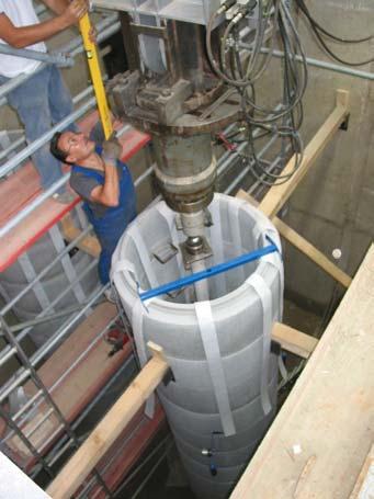
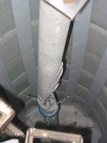
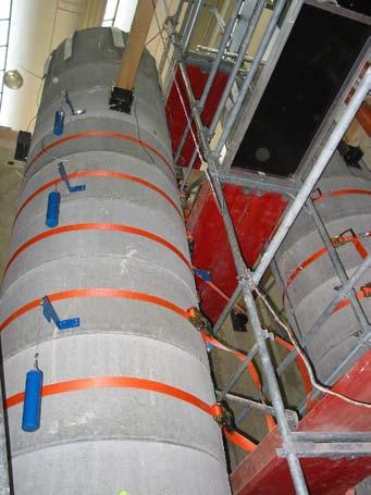
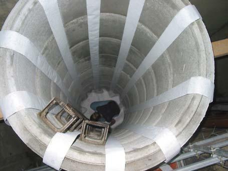
7 Large scaled loading tests Loading of 4 m long single piles Container made up with concrete segments Pile is pinned top and bottom
8 Large scaled loading tests Loading of 4 m long single piles Container made up with concrete segments Measuring devices settlement of the pile head axial loading force lateral deflection lateral deflection lateral deflection 1,0 m 1,0 m 4,0 m 1,0 m 1,0 m


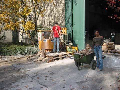
9 Large scaled loading tests Mixing up the soil in a liquid consistency Filling the containers by pumping the liquid soil following consolidation with the help of the electro osmotic effects surcharge load bridge abutment Draining system necessary settlement hydraulic jack Pumping the liquid soil test pile geotextile drainage rigid foundation
10 Large scaled loading tests Pile type I: Composite cross section GEWI28 Steel rod d = 28 mm Hardened cement slurry D = 100 mm Pile type II: Aluminum profile Thickness = 40 mm Width = 100 mm
11 Large scaled loading tests Exemplary illustration of a loading test: Alu-pile surrounded by a supporting soil of c u = 18 kpa
12 Large scaled loading tests Shear vane tests: Soil support of c u = 18 kpa Statistical analysis: residual shear strength ormal plastic clay TM w = 40,8..42,1 % I c = 0,53..0,48 Maximum shear resistance c fv Mean value Standard deviation = 18,7 k/m 2 = 2,1 K/m 2 Residual shear strength c Rv Mean value = 12,7 k/m 2 Standard deveation = 1,2 K/m 2 maximum shear strength undrained shear strength c u [kpa]
13 Large scaled loading tests Loading characteristic: Soil support of c u = 18 kpa Versuchsnummer: Settlement KFL-FLACH40x of the pile head System: axial pile force [k] Pfahlnormalkraft [k] Sudden increase of the pile head settlement while the axial normal force is decreasing o sign in the characteristic of the measured deformations that showed the pile failure in advance! Meßdauer [s] time [s] settlement of the pile head [mm] Verschiebung am Pfahlkopf u O [mm] u O Querschnitt: A Pfahlnormalkraft Verschiebung uo
14 Large scaled loading tests Lateral deflection: Soil support of c u = 18 kpa Axial force deflection w 50 k 0,4 mm 100 k 0,9 mm w w 212 k 1,2 mm 220 k (ultimate) 9 mm
15 Large scaled loading tests Analysis Results: - With an increasing soil s undrained shear strength c u the ultimate bearing capacity rises - Buckling regularly determined the ultimate state of the system, even in soils with an undrained shear strength of c u > 15 k/m 2 [k] plastic normal force pile type II plastic normal force pile type I pile type I (E p I p = 55 km 2 ) pile type II (E p I p = 38 km 2 ) c u [k/m 2 ]
16 Large scaled loading tests Analysis Results: 1000,0 o failure due to a limited pile s material strength! [k] 800,0 600,0 400,0 maximum interaction of the internal force variables (pile type II) Interaktionskurve des Pfahles FLACH40x100 Even the backing moment out of the lateral soil support is not considered 200,0 0,0? c u = 18,7 k/m 2? c u = 10,5 k/m 2 c u = 0 k/m 2 0,00 2,00 4,00 6,00 M [km]
17 Large scaled loading tests Analysis Results: For lower axial forces the lateral deflections of the pile remain very little (stiff behavior) The failure of the micro piles occurred suddenly (no sign of failure from the measured deformations) The halve waves of the buckling pile s bending curve were always smaller than the full pile s length (from joint to joint)
18 Introduction of a simple design method
19 Introduction of a simple design method Finding a static system Substituted mechanical system with a buckling length of L Hw the length of the effective buckling figure s half wave L Hw can develop freely for the most conditions in situ at the upper and lower boundaries of the soft soil layer the large scaled loading tests showed that the length of the buckling figure s half waves were smaller than the maximum possible length of 4 m; an infinite long pile can be assumed for the calculations; z L Hw
20 Introduction of a simple design method Finding a static system All forces acting on the static system with a length of L Hw T = P z p z P Lateral soil support p(z) T = 0 M M L HwLHw Bending moment in the middle w,m w 0,M
21 Introduction of a simple design method Derivation Setting up equilibrium: T = P Condition M = 0 at the pinned top z p z P M M = w,m + LHw imp P z p p(z) T = 0 M M L HwLHw Force from the lateral soil support is defined piecewise in order to a elastic-plastic soil resistance w,m w 0,M
22 Introduction of a simple design method Derivation Force P from a bi-linear approach of the supporting soil: T = P LHw P = kl w,m π LHw P = kl wki π supportion force P for: w,m <w ki for: w,m w ki P p(z) z p T = 0 M M z L HwLHw p f 1 k l for a deformation of w,m > w ki the lateral supporting force is remaining constant w,m w ki deformation w,m w 0,M
23 Introduction of a simple design method Derivation Condition M = 0 at the pinned top Assumption: The pile s material remains elastic M M = w,m + LHw imp P z p M M = Ep Ip w, M = w,m π 2 L 2 Hw E w p,m 1 Ip + π LHw + imp 2 p M L defined picewise 2 Hw
24 Introduction of a simple design method Presentation = F (w,m, E p I p, imp, L Hw and the soil support: p f and w ki ) perfect bilinear bedded beam imperfect elastically bedded beam imperfect bilinear bedded beam = w perfect elastically bedded beam,m π 2 L 2 Hw E w,m 1 Ip + π LHw + imp p buckling load according to EGESSER (elastically bedded beam): p 2 M L 2 Hw perfect unsupported beam imperfect unsupported beam buckling load according to EULER (unsupported beam): w ki w,m
25 Introduction of a simple design method Presentation L Hw is unknown! For defined parameters (soil support, imperfection and flexural rigidity) there is one length of L Hw, for which the buckling load ki is minimal ki = ki w ki π 2 L 2 Hw E p I w p ki w 2 π LHw imp ki k l L 2 Hw Vary L Hw to find the minimum and therefore effective buckling length! effective ki effective L Hw L Hw
26 Introduction of a simple design method Summary of the calculation sequence: 1.) Define the parameters of the lateral soil support p f und w ki 2.) Define an imperfection and the flexural rigidity of the pile s cross section 3.) Evaluate the effective buckling half wave's length L Hw 4.) Calculate the buckling load ki 5.) Check if the pile s material strength governs the maximum bearing capacity (this means: does the pile s material yield before the buckling load is reached ) You may download an Excel-Sheet at
27 Introduction of a simple design method Back-calculation of the large scaled tests Pile type I p f = 10 c u b k l = 100 c u imp = 600 Used: half side cracked cross section (no tension stresses in the hardened cement) [k] mm hardened cement: C20/ p f = 6 c u b k l = 60 c u imp = c u [k/m 2 ] 100 mm E p I p = 55 km 2 GEWI28: BSt 500 S
28 Introduction of a simple design method Back-calculation of the large scaled tests Pile type II 1000,0 800,0 [k] 600,0 400,0 k l = 100 c u p f = 7 c u D k l = 100 c u p f = 10 c u D Alu-pile: 200,0 0,0 k l = 70 c u p f = 7 c u D c u [k/m 2 ] Al Mg Si 0,5 40 mm 100 mm E p I p = 38 km 2
29 Summary In (very) soft soils pile buckling should always be verified! With the help of the presented design method the main effects of the loading tests can be considered in basic. The insecurities upon the design method is based and which are recognizable comparing the theoretical results with the data form the pile load tests must be covered by partial safety factors on the structural part and the soil resistance. - Compound effects steel-concrete - Soil resistance (w ki, p f ) - Viscous influence creep and relaxation

30 Thank you for your Attention!
31

32 Research work at the Zentrum Geotechnik Introduction Literature research beam supported by springs Development of a numerical FE-Model Model scaled tests In situ field load test Large scaled loading tests Development of a simple calculation scheme characteristic of the lateral reaction forces elastisch or elastisch-plastisch supporting force lateral deflection
33 Research work at the Zentrum Geotechnik Introduction Literature research Development of a numerical FE-Model Model scaled tests In situ field load test Large scaled loading tests Development of a simple calculation scheme buckling Knicklast load k [k] Loading tests on 80 cm long model piles Varying soil strengths and cross sections Comparison of the test results with the predicted buckling loads (both numerical FEM and published calculation methods) elastic characteristic of the springs elastic-plastic characteristic of the springs undrainierte Scherfestigkeit cu [k/m²] undrained shear strengh c u [k/m 2 ]
34 Research work at the Zentrum Geotechnik Introduction Literature research Development of a numerical FE-Model Model scaled tests In situ field load test Large scaled loading tests Development of a simple calculation scheme Loading test of a GEWIpile in soft, organic soil Sudden pile failure at a load very little above the design load
35 Large scaled loading tests Results of the loading tests of three unsupported composite piles Why to use an aluminum pile? k90 Buckling load of the unsupported pole (EULER II) Axial pile force [k] u Loading an pile with such an inelastic behavior due to its cross section material (unpredictable crack propagation of the concrete) is improper to qualify the lateral soil support! u 20 u 10 0 w u w u Lateral deflection in the middle of the pile w,m [mm]
36 Large scaled loading tests Pile type II: Aluminum profile Some pile is needed which behaves elastically over a wide range of lateral displacements and which reproduces the buckling load according to EULER in the unsupported case. Solution: A aluminum pile that has a similar flexural rigidity compared to the cracked composite cross section. Composite cross section, cracked half side 50 mm 100 mm E p I p = 55 km 2 Aluminum profile Cement: C20/25 GEWI28: BSt 500 S Al Mg Si 0,5 40 mm 100 mm E p I p = 38 km 2
37 Large scaled loading tests Test results obtained by loading of an unsupported alu-pile Ultimate bearing capacity of the 200 unsupported composite-piles: 180 k = 55, 22 und 19 k axial pile force [k] Alupile: always k = 22 k lateral displacement in the middle of the pile w [mm] time [s]
38 Introduction of a simple design method Derivation Assumption of a sinus shaped deformation due to imperfection w 0 π (z) = w z 0,M sin LHw P Assumption of sinus shaped bending curves w π (z) = w,m sin z LHw This yields to a sinus shaped form of the load per unit length due to the lateral soil support π p(z) = p z M sin LHw p(z) z p T = 0 w,m M M z w 0,M T = P L HwLHw
39 Introduction of a simple design method Is the decisive buckling load ki the ultimate axial load u of the micropile? C w M,pl = M π pl 2 L E 2 Hw p I p 1 pl α D The pile s material may yield before the buckling load is reached. In this case the pile s material strength governs the ultimate load. axial pile force case 2 case 1 B w M,pl case 2 w M,pl case 1 M= M pl 1 pl α A lateral deformation w,m
Critical Load columns buckling critical load
 Buckling of Columns Buckling of Columns Critical Load Some member may be subjected to compressive loadings, and if these members are long enough to cause the member to deflect laterally or sideway. To
Mechanical Design in Optical Engineering
 OPTI Buckling Buckling and Stability: As we learned in the previous lectures, structures may fail in a variety of ways, depending on the materials, load and support conditions. We had two primary concerns:
Lecture 15 Strain and stress in beams
 Spring, 2019 ME 323 Mechanics of Materials Lecture 15 Strain and stress in beams Reading assignment: 6.1 6.2 News: Instructor: Prof. Marcial Gonzalez Last modified: 1/6/19 9:42:38 PM Beam theory (@ ME
Civil Engineering Design (1) Design of Reinforced Concrete Columns 2006/7
 Design of Reinforced Concrete Columns 2006/7") Civil Engineering Design (1) Design of Reinforced Concrete Columns 2006/7 Dr. Colin Caprani, Chartered Engineer 1 Contents 1. Introduction... 3 1.1 Background... 3 1.2 Failure Modes... 5 1.3 Design Aspects...
Civil Engineering Design (1) Design of Reinforced Concrete Columns 2006/7 Dr. Colin Caprani, Chartered Engineer 1 Contents 1. Introduction... 3 1.1 Background... 3 1.2 Failure Modes... 5 1.3 Design Aspects...
EMA 3702 Mechanics & Materials Science (Mechanics of Materials) Chapter 10 Columns
 Chapter 10 Columns") EMA 370 Mechanics & Materials Science (Mechanics of Materials) Chapter 10 Columns Columns Introduction Columns are vertical prismatic members subjected to compressive forces Goals: 1. Study the stability
EMA 370 Mechanics & Materials Science (Mechanics of Materials) Chapter 10 Columns Columns Introduction Columns are vertical prismatic members subjected to compressive forces Goals: 1. Study the stability
ENG1001 Engineering Design 1
 ENG1001 Engineering Design 1 Structure & Loads Determine forces that act on structures causing it to deform, bend, and stretch Forces push/pull on objects Structures are loaded by: > Dead loads permanent
Finite Element Modelling with Plastic Hinges
 01/02/2016 Marco Donà Finite Element Modelling with Plastic Hinges 1 Plastic hinge approach A plastic hinge represents a concentrated post-yield behaviour in one or more degrees of freedom. Hinges only
How materials work. Compression Tension Bending Torsion
 Materials How materials work Compression Tension Bending Torsion Elemental material atoms: A. Composition a) Nucleus: protons (+), neutrons (0) b) Electrons (-) B. Neutral charge, i.e., # electrons = #
GEOTECHNICAL ENGINEERING ECG 503 LECTURE NOTE ANALYSIS AND DESIGN OF RETAINING STRUCTURES
 GEOTECHNICAL ENGINEERING ECG 503 LECTURE NOTE 07 3.0 ANALYSIS AND DESIGN OF RETAINING STRUCTURES LEARNING OUTCOMES Learning outcomes: At the end of this lecture/week the students would be able to: Understand
ε t increases from the compressioncontrolled Figure 9.15: Adjusted interaction diagram
 CHAPTER NINE COLUMNS 4 b. The modified axial strength in compression is reduced to account for accidental eccentricity. The magnitude of axial force evaluated in step (a) is multiplied by 0.80 in case
Mechanics of Materials Primer
 Mechanics of Materials rimer Notation: A = area (net = with holes, bearing = in contact, etc...) b = total width of material at a horizontal section d = diameter of a hole D = symbol for diameter E = modulus
Prof. Dr.-Ing. Martin Achmus Institute of Soil Mechanics, Foundation Engineering and Waterpower Engineering. Monopile design
 Prof. Dr.-Ing. Martin Achmus Institute of Soil Mechanics, Foundation Engineering and Waterpower Engineering Monopile design Addis Ababa, September 2010 Monopile design Presentation structure: Design proofs
five Mechanics of Materials 1 ARCHITECTURAL STRUCTURES: FORM, BEHAVIOR, AND DESIGN DR. ANNE NICHOLS SUMMER 2017 lecture
 ARCHITECTURAL STRUCTURES: FORM, BEHAVIOR, AND DESIGN DR. ANNE NICHOLS SUMMER 2017 lecture five mechanics www.carttalk.com of materials Mechanics of Materials 1 Mechanics of Materials MECHANICS MATERIALS
Elastic Stability Of Columns
 Elastic Stability Of Columns Introduction: Structural members which carry compressive loads may be divided into two broad categories depending on their relative lengths and cross-sectional dimensions.
ME Final Exam. PROBLEM NO. 4 Part A (2 points max.) M (x) y. z (neutral axis) beam cross-sec+on. 20 kip ft. 0.2 ft. 10 ft. 0.1 ft.
 M (x) y. z (neutral axis) beam cross-sec+on. 20 kip ft. 0.2 ft. 10 ft. 0.1 ft.") ME 323 - Final Exam Name December 15, 2015 Instructor (circle) PROEM NO. 4 Part A (2 points max.) Krousgrill 11:30AM-12:20PM Ghosh 2:30-3:20PM Gonzalez 12:30-1:20PM Zhao 4:30-5:20PM M (x) y 20 kip ft 0.2
ME 323 - Final Exam Name December 15, 2015 Instructor (circle) PROEM NO. 4 Part A (2 points max.) Krousgrill 11:30AM-12:20PM Ghosh 2:30-3:20PM Gonzalez 12:30-1:20PM Zhao 4:30-5:20PM M (x) y 20 kip ft 0.2
Piles and Pile Foundations
 Piles and Pile Foundations Carlo Viggiani, Alessandro Mandolini and Gianpiero Russo * j \ Spon Press an imprint of Taylor & Francis LONDON AND NEWYORK Contents List of illustrations Introduction PART I
1.8 Unconfined Compression Test
 1-49 1.8 Unconfined Compression Test - It gives a quick and simple measurement of the undrained strength of cohesive, undisturbed soil specimens. 1) Testing method i) Trimming a sample. Length-diameter
7.5 Elastic Buckling Columns and Buckling
 7.5 Elastic Buckling The initial theory of the buckling of columns was worked out by Euler in 1757, a nice example of a theory preceding the application, the application mainly being for the later invented
Axially Loaded Piles
 Axially Loaded Piles 1 t- Curve Method using Finite Element Analysis The stress-strain relationship for an axially loaded pile can be described through three loading mechanisms: axial deformation in the
Chapter 12 Elastic Stability of Columns
 Chapter 12 Elastic Stability of Columns Axial compressive loads can cause a sudden lateral deflection (Buckling) For columns made of elastic-perfectly plastic materials, P cr Depends primarily on E and
Seismic Pushover Analysis Using AASHTO Guide Specifications for LRFD Seismic Bridge Design
 Seismic Pushover Analysis Using AASHTO Guide Specifications for LRFD Seismic Bridge Design Elmer E. Marx, Alaska Department of Transportation and Public Facilities Michael Keever, California Department
D : SOLID MECHANICS. Q. 1 Q. 9 carry one mark each. Q.1 Find the force (in kn) in the member BH of the truss shown.
 in the member BH of the truss shown.") D : SOLID MECHANICS Q. 1 Q. 9 carry one mark each. Q.1 Find the force (in kn) in the member BH of the truss shown. Q.2 Consider the forces of magnitude F acting on the sides of the regular hexagon having
D : SOLID MECHANICS Q. 1 Q. 9 carry one mark each. Q.1 Find the force (in kn) in the member BH of the truss shown. Q.2 Consider the forces of magnitude F acting on the sides of the regular hexagon having
Theory of Shear Strength
 MAJ 1013 ADVANCED SOIL MECHANICS Theory of Shear Strength Prepared by, Dr. Hetty 1 Strength of different materials Steel Concrete Soil Tensile strength Compressive strength Shear strength Complex behavior
December 10, PROBLEM NO points max.
 PROBLEM NO. 1 25 points max. PROBLEM NO. 2 25 points max. B 3A A C D A H k P L 2L Given: Consider the structure above that is made up of rod segments BC and DH, a spring of stiffness k and rigid connectors
March 24, Chapter 4. Deflection and Stiffness. Dr. Mohammad Suliman Abuhaiba, PE
 Chapter 4 Deflection and Stiffness 1 2 Chapter Outline Spring Rates Tension, Compression, and Torsion Deflection Due to Bending Beam Deflection Methods Beam Deflections by Superposition Strain Energy Castigliano
SHEAR STRENGTH OF SOIL
 SHEAR STRENGTH OF SOIL Necessity of studying Shear Strength of soils : Soil failure usually occurs in the form of shearing along internal surface within the soil. Shear Strength: Thus, structural strength
Chapter (11) Pile Foundations
 Pile Foundations") Chapter (11) Introduction Piles are structural members that are made of steel, concrete, or timber. They are used to build pile foundations (classified as deep foundations) which cost more than shallow
Chapter (11) Introduction Piles are structural members that are made of steel, concrete, or timber. They are used to build pile foundations (classified as deep foundations) which cost more than shallow
Engineeringmanuals. Part2
 Engineeringmanuals Part2 Engineering manuals for GEO5 programs Part 2 Chapter 1-12, refer to Engineering Manual Part 1 Chapter 13. Pile Foundations Introduction... 2 Chapter 14. Analysis of vertical load-bearing
Deep Foundations 2. Load Capacity of a Single Pile
 Deep Foundations 2 Load Capacity of a Single Pile All calculations of pile capacity are approximate because it is almost impossible to account for the variability of soil types and the differences in the
Seismic design of bridges
 NATIONAL TECHNICAL UNIVERSITY OF ATHENS LABORATORY FOR EARTHQUAKE ENGINEERING Seismic design of bridges Lecture 3 Ioannis N. Psycharis Capacity design Purpose To design structures of ductile behaviour
Mechanics of Materials CIVL 3322 / MECH 3322
 Mechanics of Materials CIVL 3322 / MECH 3322 2 3 4 5 6 7 8 9 10 A Quiz 11 A Quiz 12 A Quiz 13 A Quiz 14 A Quiz 15 A Quiz 16 In Statics, we spent most of our time looking at reactions at supports Two variations
Laboratory 4 Topic: Buckling
 Laboratory 4 Topic: Buckling Objectives: To record the load-deflection response of a clamped-clamped column. To identify, from the recorded response, the collapse load of the column. Introduction: Buckling
Introduction to Soil Mechanics
 Introduction to Soil Mechanics Sela Sode and Colin Jones WILEY Blackwell Contents Preface Dedication and Acknowledgments List of Symbols Soil Structure 1.1 Volume relationships 1.1.1 Voids ratio (e) 1.1.2
Mechanics of Materials II. Chapter III. A review of the fundamental formulation of stress, strain, and deflection
 Mechanics of Materials II Chapter III A review of the fundamental formulation of stress, strain, and deflection Outline Introduction Assumtions and limitations Axial loading Torsion of circular shafts
INFLUENCE OF FLANGE STIFFNESS ON DUCTILITY BEHAVIOUR OF PLATE GIRDER
 International Journal of Civil Structural 6 Environmental And Infrastructure Engineering Research Vol.1, Issue.1 (2011) 1-15 TJPRC Pvt. Ltd.,. INFLUENCE OF FLANGE STIFFNESS ON DUCTILITY BEHAVIOUR OF PLATE
Interpretation of Pile Integrity Test (PIT) Results
 Results") Annual Transactions of IESL, pp. 78-84, 26 The Institution of Engineers, Sri Lanka Interpretation of Pile Integrity Test (PIT) Results H. S. Thilakasiri Abstract: A defect present in a pile will severely
Annual Transactions of IESL, pp. 78-84, 26 The Institution of Engineers, Sri Lanka Interpretation of Pile Integrity Test (PIT) Results H. S. Thilakasiri Abstract: A defect present in a pile will severely
Influence of residual stresses in the structural behavior of. tubular columns and arches. Nuno Rocha Cima Gomes
 October 2014 Influence of residual stresses in the structural behavior of Abstract tubular columns and arches Nuno Rocha Cima Gomes Instituto Superior Técnico, Universidade de Lisboa, Portugal Contact:
A METHOD OF LOAD INCREMENTS FOR THE DETERMINATION OF SECOND-ORDER LIMIT LOAD AND COLLAPSE SAFETY OF REINFORCED CONCRETE FRAMED STRUCTURES
 A METHOD OF LOAD INCREMENTS FOR THE DETERMINATION OF SECOND-ORDER LIMIT LOAD AND COLLAPSE SAFETY OF REINFORCED CONCRETE FRAMED STRUCTURES Konuralp Girgin (Ph.D. Thesis, Institute of Science and Technology,
Structural Steelwork Eurocodes Development of A Trans-national Approach
 Structural Steelwork Eurocodes Development of A Trans-national Approach Course: Eurocode Module 7 : Worked Examples Lecture 0 : Simple braced frame Contents: 1. Simple Braced Frame 1.1 Characteristic Loads
EN Eurocode 7. Section 3 Geotechnical Data Section 6 Spread Foundations. Trevor L.L. Orr Trinity College Dublin Ireland.
 EN 1997 1: Sections 3 and 6 Your logo Brussels, 18-20 February 2008 Dissemination of information workshop 1 EN 1997-1 Eurocode 7 Section 3 Geotechnical Data Section 6 Spread Foundations Trevor L.L. Orr
EUROCODE EN SEISMIC DESIGN OF BRIDGES
 Brussels, 18-20 February 2008 Dissemination of information workshop 1 EUROCODE EN1998-2 SEISMIC DESIGN OF BRIDGES Basil Kolias Basic Requirements Brussels, 18-20 February 2008 Dissemination of information
INTRODUCTION TO STATIC ANALYSIS PDPI 2013
 INTRODUCTION TO STATIC ANALYSIS PDPI 2013 What is Pile Capacity? When we load a pile until IT Fails what is IT Strength Considerations Two Failure Modes 1. Pile structural failure controlled by allowable
Landslide FE Stability Analysis
 Landslide FE Stability Analysis L. Kellezi Dept. of Geotechnical Engineering, GEO-Danish Geotechnical Institute, Denmark S. Allkja Altea & Geostudio 2000, Albania P. B. Hansen Dept. of Geotechnical Engineering,
Module 4 : Deflection of Structures Lecture 4 : Strain Energy Method
 Module 4 : Deflection of Structures Lecture 4 : Strain Energy Method Objectives In this course you will learn the following Deflection by strain energy method. Evaluation of strain energy in member under
Analysis of CMC-Supported Embankments Considering Soil Arching
 Analysis of CMC-Supported Embankments Considering Soil Arching Balaka Ghosh 1, Behzad Fatahi 2, Hadi Khabbaz 3, and A. H. M. Kamruzzaman 4 1 PhD Candidate, School of Civil and Environmental Engineering,
Theory of Shear Strength
 SKAA 1713 SOIL MECHANICS Theory of Shear Strength Prepared by, Dr. Hetty 1 SOIL STRENGTH DEFINITION Shear strength of a soil is the maximum internal resistance to applied shearing forces The maximum or
Chapter Two: Mechanical Properties of materials
 Chapter Two: Mechanical Properties of materials Time : 16 Hours An important consideration in the choice of a material is the way it behave when subjected to force. The mechanical properties of a material
Chapter (12) Instructor : Dr. Jehad Hamad
 Instructor : Dr. Jehad Hamad") Chapter (12) Instructor : Dr. Jehad Hamad 2017-2016 Chapter Outlines Shear strength in soils Direct shear test Unconfined Compression Test Tri-axial Test Shear Strength The strength of a material is the
Chapter (12) Instructor : Dr. Jehad Hamad 2017-2016 Chapter Outlines Shear strength in soils Direct shear test Unconfined Compression Test Tri-axial Test Shear Strength The strength of a material is the
Mechanical Design in Optical Engineering. For a prismatic bar of length L in tension by axial forces P we have determined:
 Deformation of Axial Members For a prismatic bar of length L in tension by axial forces P we have determined: σ = P A δ ε = L It is important to recall that the load P must act on the centroid of the cross
Accordingly, the nominal section strength [resistance] for initiation of yielding is calculated by using Equation C-C3.1.
![Accordingly, the nominal section strength [resistance] for initiation of yielding is calculated by using Equation C-C3.1.](/thumbs/89/98617066.jpg "Accordingly, the nominal section strength [resistance] for initiation of yielding is calculated by using Equation C-C3.1.") C3 Flexural Members C3.1 Bending The nominal flexural strength [moment resistance], Mn, shall be the smallest of the values calculated for the limit states of yielding, lateral-torsional buckling and distortional
C3 Flexural Members C3.1 Bending The nominal flexural strength [moment resistance], Mn, shall be the smallest of the values calculated for the limit states of yielding, lateral-torsional buckling and distortional
COLUMNS: BUCKLING (DIFFERENT ENDS)
") COLUMNS: BUCKLING (DIFFERENT ENDS) Buckling of Long Straight Columns Example 4 Slide No. 1 A simple pin-connected truss is loaded and supported as shown in Fig. 1. All members of the truss are WT10 43
COLUMNS: BUCKLING (DIFFERENT ENDS) Buckling of Long Straight Columns Example 4 Slide No. 1 A simple pin-connected truss is loaded and supported as shown in Fig. 1. All members of the truss are WT10 43
Investigation of Pile- Soil Interaction Subjected to Lateral Loads in Layered Soils
 American J. of Engineering and Applied Sciences (): 76-8, 008 ISSN 9-700 008 Science Publications Investigation of Pile- Soil Interaction Subjected to Lateral Loads in Layered Soils A. Avaei, Abdoul R.
Design of Beams (Unit - 8)
") Design of Beams (Unit - 8) Contents Introduction Beam types Lateral stability of beams Factors affecting lateral stability Behaviour of simple and built - up beams in bending (Without vertical stiffeners)
Design of Beams (Unit - 8) Contents Introduction Beam types Lateral stability of beams Factors affecting lateral stability Behaviour of simple and built - up beams in bending (Without vertical stiffeners)
Reinforced Soil Structures Reinforced Soil Walls. Prof K. Rajagopal Department of Civil Engineering IIT Madras, Chennai
 Geosynthetics and Reinforced Soil Structures Reinforced Soil Walls continued Prof K. Rajagopal Department of Civil Engineering IIT Madras, Chennai e-mail: gopalkr@iitm.ac.inac in Outline of the Lecture
(2) ANALYSIS OF INDETERMINATE STRUCTRES
 ANALYSIS OF INDETERMINATE STRUCTRES") Chapter (2) ANALYSIS OF INDETERMINATE STRUCTRES 1.1 Statically Indeterminate Structures A structure of any type is classified as statically indeterminate when the number of unknown reaction or internal
Chapter (2) ANALYSIS OF INDETERMINATE STRUCTRES 1.1 Statically Indeterminate Structures A structure of any type is classified as statically indeterminate when the number of unknown reaction or internal
Support Idealizations
 IVL 3121 nalysis of Statically Determinant Structures 1/12 nalysis of Statically Determinate Structures nalysis of Statically Determinate Structures The most common type of structure an engineer will analyze
BOOK OF COURSE WORKS ON STRENGTH OF MATERIALS FOR THE 2 ND YEAR STUDENTS OF THE UACEG
 BOOK OF COURSE WORKS ON STRENGTH OF MATERIALS FOR THE ND YEAR STUDENTS OF THE UACEG Assoc.Prof. Dr. Svetlana Lilkova-Markova, Chief. Assist. Prof. Dimitar Lolov Sofia, 011 STRENGTH OF MATERIALS GENERAL
MECH 401 Mechanical Design Applications
 MECH 40 Mechanical Design Applications Dr. M. K. O Malley Master Notes Spring 008 Dr. D. M. McStravick Rice University Design Considerations Stress Deflection Strain Stiffness Stability Often the controlling
Sabah Shawkat Cabinet of Structural Engineering Walls carrying vertical loads should be designed as columns. Basically walls are designed in
 Sabah Shawkat Cabinet of Structural Engineering 17 3.6 Shear walls Walls carrying vertical loads should be designed as columns. Basically walls are designed in the same manner as columns, but there are
ENCE 455 Design of Steel Structures. III. Compression Members
 ENCE 455 Design of Steel Structures III. Compression Members C. C. Fu, Ph.D., P.E. Civil and Environmental Engineering Department University of Maryland Compression Members Following subjects are covered:
Structural Steelwork Eurocodes Development of A Trans-national Approach
 Structural Steelwork Eurocodes Development of A Trans-national Approach Course: Eurocode 3 Module 7 : Worked Examples Lecture 20 : Simple braced frame Contents: 1. Simple Braced Frame 1.1 Characteristic
Verification of a Micropile Foundation
 Engineering manual No. 36 Update 02/2018 Verification of a Micropile Foundation Program: File: Pile Group Demo_manual_en_36.gsp The objective of this engineering manual is to explain the application of
Mechanical Properties of Materials
 Mechanical Properties of Materials Strains Material Model Stresses Learning objectives Understand the qualitative and quantitative description of mechanical properties of materials. Learn the logic of
REPORT. No.: D3.3 part 4. Axially loaded sandwich panels
 REPORT Axially loaded sandich panels Publisher: Saskia Käpplein Thomas isiek Karlsruher Institut für Technologie (KIT) Versuchsanstalt für Stahl, Holz und Steine Task: 3.4 Object: Design of axially loaded
MODULE C: COMPRESSION MEMBERS
 MODULE C: COMPRESSION MEMBERS This module of CIE 428 covers the following subjects Column theory Column design per AISC Effective length Torsional and flexural-torsional buckling Built-up members READING:
THE COLLAPSE LOAD IN SUBMARINE PIPELINES UNDER COMPRESSIVE LOAD AND INTERNAL PRESSURE
 SDSS Rio 010 STABILITY AND DUCTILITY OF STEEL STRUCTURES E. Batista,. Vellasco, L. de Lima (Eds.) Rio de Janeiro, Brazil, September 8-10, 010 THE COLLASE LOAD IN SUBMARINE IELINES UNDER COMRESSIVE LOAD
PRINCIPLES OF GEOTECHNICAL ENGINEERING
 PRINCIPLES OF GEOTECHNICAL ENGINEERING Fourth Edition BRAJA M. DAS California State University, Sacramento I(T)P Boston Albany Bonn Cincinnati London Madrid Melbourne Mexico City New York Paris San Francisco
twenty steel construction: columns & tension members ARCHITECTURAL STRUCTURES: FORM, BEHAVIOR, AND DESIGN DR. ANNE NICHOLS FALL 2013 lecture
 ARCHITECTURAL STRUCTURES: FORM, BEHAVIOR, AND DESIGN DR. ANNE NICHOLS Cor-Ten Steel Sculpture By Richard Serra Museum of Modern Art Fort Worth, TX (AISC - Steel Structures of the Everyday) FALL 2013 lecture
Chapter 4-b Axially Loaded Members
 CIVL 222 STRENGTH OF MATERIALS Chapter 4-b Axially Loaded Members AXIAL LOADED MEMBERS Today s Objectives: Students will be able to: a) Determine the elastic deformation of axially loaded member b) Apply
Chapter 4 Deflection and Stiffness
 Chapter 4 Deflection and Stiffness Asst. Prof. Dr. Supakit Rooppakhun Chapter Outline Deflection and Stiffness 4-1 Spring Rates 4-2 Tension, Compression, and Torsion 4-3 Deflection Due to Bending 4-4 Beam
Estimation of the Residual Stiffness of Fire-Damaged Concrete Members
 Copyright 2011 Tech Science Press CMC, vol.22, no.3, pp.261-273, 2011 Estimation of the Residual Stiffness of Fire-Damaged Concrete Members J.M. Zhu 1, X.C. Wang 1, D. Wei 2, Y.H. Liu 2 and B.Y. Xu 2 Abstract:
Chapter 1 General Introduction Instructor: Dr. Mürüde Çelikağ Office : CE Building Room CE230 and GE241
 CIVL222 STRENGTH OF MATERIALS Chapter 1 General Introduction Instructor: Dr. Mürüde Çelikağ Office : CE Building Room CE230 and GE241 E-mail : murude.celikag@emu.edu.tr 1. INTRODUCTION There are three
Module 9 : Foundation on rocks. Content
 FOUNDATION ON ROCKS Content 9.1 INTRODUCTION 9.2 FOUNDATION TYPES ON ROCKS 9.3 BEARING CAPCITY- SHALLOW FOUNDATION 9.3.1 Ultimate bearing capacity 9.3.2 Safe bearing pressure 9.3.3 Estimation of bearing
NCEES Fundamentals of Engineering (FE) Examination CIVIL EXAM SPECIFICATIONS
 Examination CIVIL EXAM SPECIFICATIONS") NCEES Fundamentals of Engineering (FE) Examination CIVIL EXAM SPECIFICATIONS Effective Beginning with the April 2009 Examinations The FE examination is an 8-hour supplied-reference examination: 120 questions
NCEES Fundamentals of Engineering (FE) Examination CIVIL EXAM SPECIFICATIONS Effective Beginning with the April 2009 Examinations The FE examination is an 8-hour supplied-reference examination: 120 questions
INELASTIC RESPONSES OF LONG BRIDGES TO ASYNCHRONOUS SEISMIC INPUTS
 13 th World Conference on Earthquake Engineering Vancouver, B.C., Canada August 1-6, 24 Paper No. 638 INELASTIC RESPONSES OF LONG BRIDGES TO ASYNCHRONOUS SEISMIC INPUTS Jiachen WANG 1, Athol CARR 1, Nigel
CE 221: MECHANICS OF SOLIDS I CHAPTER 1: STRESS. Dr. Krisada Chaiyasarn Department of Civil Engineering, Faculty of Engineering Thammasat university
 CE 221: MECHANICS OF SOLIDS I CHAPTER 1: STRESS By Dr. Krisada Chaiyasarn Department of Civil Engineering, Faculty of Engineering Thammasat university Agenda Introduction to your lecturer Introduction
Theory at a Glance (for IES, GATE, PSU)
") 1. Stress and Strain Theory at a Glance (for IES, GATE, PSU) 1.1 Stress () When a material is subjected to an external force, a resisting force is set up within the component. The internal resistance force
1. Stress and Strain Theory at a Glance (for IES, GATE, PSU) 1.1 Stress () When a material is subjected to an external force, a resisting force is set up within the component. The internal resistance force
STEEL JOINTS - COMPONENT METHOD APPLICATION
 Bulletin of the Transilvania University of Braşov Vol. 5 (54) - 2012 Series 1: Special Issue No. 1 STEEL JOINTS - COPONENT ETHOD APPLICATION D. RADU 1 Abstract: As long as the rotation joint stiffness
CPT Guide 5 th Edition. CPT Applications - Deep Foundations. Gregg Drilling & Testing, Inc. Dr. Peter K. Robertson Webinar # /2/2013
 Gregg Drilling & Testing, Inc. Site Investigation Experts CPT Applications - Deep Foundations Dr. Peter K. Robertson Webinar #6 2013 CPT Guide 5 th Edition Robertson & Cabal (Robertson) 5 th Edition 2012
Introduction to Continuous Systems. Continuous Systems. Strings, Torsional Rods and Beams.
 Outline of Continuous Systems. Introduction to Continuous Systems. Continuous Systems. Strings, Torsional Rods and Beams. Vibrations of Flexible Strings. Torsional Vibration of Rods. Bernoulli-Euler Beams.
Bracing for Earthquake Resistant Design
 h z (Draft, 010) Bracing for Earthquae Resistant Design 1 September 18, 00 (010 update) Rigid Roof Idealization and Column Stiffness Relative to the columns, the roof structural system might be quite rigid,
D1. A normally consolidated clay has the following void ratio e versus effective stress σ relationship obtained in an oedometer test.
 (d) COMPRESSIBILITY AND CONSOLIDATION D1. A normally consolidated clay has the following void ratio e versus effective stress σ relationship obtained in an oedometer test. (a) Plot the e - σ curve. (b)
MECHANICS OF MATERIALS
 CHTER MECHNICS OF MTERILS 10 Ferdinand. Beer E. Russell Johnston, Jr. Columns John T. DeWolf cture Notes: J. Walt Oler Texas Tech University 006 The McGraw-Hill Companies, Inc. ll rights reserved. Columns
Fundamentals of Structural Design Part of Steel Structures
 Fundamentals of Structural Design Part of Steel Structures Civil Engineering for Bachelors 133FSTD Teacher: Zdeněk Sokol Office number: B619 1 Syllabus of lectures 1. Introduction, history of steel structures,
MATERIALS. Why do things break? Why are some materials stronger than others? Why is steel tough? Why is glass brittle?
 MATERIALS Why do things break? Why are some materials stronger than others? Why is steel tough? Why is glass brittle? What is toughness? strength? brittleness? Elemental material atoms: A. Composition
Application of cyclic accumulation models for undrained and partially drained general boundary value problems
 Application of cyclic accumulation models for undrained and partially drained general boundary value problems A. M. Page Risueño Yngres Dag 2014, May 15 th 2014 Introduction Cyclic loads in geotechnical
Unit 18 Other Issues In Buckling/Structural Instability
 Unit 18 Other Issues In Buckling/Structural Instability Readings: Rivello Timoshenko Jones 14.3, 14.5, 14.6, 14.7 (read these at least, others at your leisure ) Ch. 15, Ch. 16 Theory of Elastic Stability
CHAPTER 4. ANALYSIS AND DESIGN OF COLUMNS
 4.1. INTRODUCTION CHAPTER 4. ANALYSIS AND DESIGN OF COLUMNS A column is a vertical structural member transmitting axial compression loads with or without moments. The cross sectional dimensions of a column
CHAPTER 8 ANALYSES OF THE LATERAL LOAD TESTS AT THE ROUTE 351 BRIDGE
 CHAPTER ANALYSES OF THE LATERAL LOAD TESTS AT THE ROUTE 351 BRIDGE.1 INTRODUCTION An important objective of this research is to determine whether accurate analyses of the lateral load-deflection behavior
Lesson 25. Static Pile Load Testing, O-cell, and Statnamic. Reference Manual Chapter 18
 Lesson 25 Static Pile Load Testing, O-cell, and Statnamic Reference Manual Chapter 18 STATIC LOAD TESTING Most accurate method to determine static pile capacity Perform at design or construction stage
cyclic loading in Germany
 Note to actual al design of micropiles under axial cyclic loading in Germany according to DIN 1054 and further guidelines Jennifer Kleih 9th International Workshop on Micropiles London 13th May 2009 Outline
Johns Hopkins University What is Engineering? M. Karweit MATERIALS
 Why do things break? Why are some materials stronger than others? Why is steel tough? Why is glass brittle? What is toughness? strength? brittleness? Elemental material atoms: MATERIALS A. Composition
Nomenclature. Length of the panel between the supports. Width of the panel between the supports/ width of the beam
 omenclature a b c f h Length of the panel between the supports Width of the panel between the supports/ width of the beam Sandwich beam/ panel core thickness Thickness of the panel face sheet Sandwich
 Comparison of shear pile force and moment in slippage reinforced with shear pile Mona Mohamadi 1, Abolfazl Eslami, Farhad Nabizade 1 1. Department of Technology, Guilan University, Iran. Department of
Compression Members. ENCE 455 Design of Steel Structures. III. Compression Members. Introduction. Compression Members (cont.)
") ENCE 455 Design of Steel Structures III. Compression Members C. C. Fu, Ph.D., P.E. Civil and Environmental Engineering Department University of Maryland Compression Members Following subjects are covered:
ENCE 455 Design of Steel Structures III. Compression Members C. C. Fu, Ph.D., P.E. Civil and Environmental Engineering Department University of Maryland Compression Members Following subjects are covered:
D : SOLID MECHANICS. Q. 1 Q. 9 carry one mark each.
 GTE 2016 Q. 1 Q. 9 carry one mark each. D : SOLID MECHNICS Q.1 single degree of freedom vibrating system has mass of 5 kg, stiffness of 500 N/m and damping coefficient of 100 N-s/m. To make the system
Entrance exam Master Course
 - 1 - Guidelines for completion of test: On each page, fill in your name and your application code Each question has four answers while only one answer is correct. o Marked correct answer means 4 points
ME 243. Mechanics of Solids
 ME 243 Mechanics of Solids Lecture 2: Stress and Strain Ahmad Shahedi Shakil Lecturer, Dept. of Mechanical Engg, BUET E-mail: sshakil@me.buet.ac.bd, shakil6791@gmail.com Website: teacher.buet.ac.bd/sshakil
Chapter 11. Displacement Method of Analysis Slope Deflection Method
 Chapter 11 Displacement ethod of Analysis Slope Deflection ethod Displacement ethod of Analysis Two main methods of analyzing indeterminate structure Force method The method of consistent deformations
Lecture Slides. Chapter 4. Deflection and Stiffness. The McGraw-Hill Companies 2012
 Lecture Slides Chapter 4 Deflection and Stiffness The McGraw-Hill Companies 2012 Chapter Outline Force vs Deflection Elasticity property of a material that enables it to regain its original configuration