Propagation of Seismic Waves through Liquefied Soils
|
|
|
- Cuthbert Mosley
- 6 years ago
- Views:
Transcription
1 Propagation of Seismic Waves through Liquefied Soils Mahdi Taiebat a,b,, Boris Jeremić b, Yannis F. Dafalias b,c, Amir M. Kaynia a, Zhao Cheng d a Norwegian Geotechnical Institute, P.O. Box 393 Ullevaal Stadion, N-86 Oslo, Norway b Department of Civil and Environmental Engineering, University of California, Davis, CA 95616, USA c Department of Mechanics, National Technical University of Athens, Zographou 1578, Hellas d Earth Mechanics Inc. Oakland CA 94621, USA Abstract For prediction of the earthquake response of saturated porous media it is essential to correctly simulate the generation, redistribution and dissipation of excess pore water pressures during and after earthquake shaking. To this end, a reliable numerical tool requires a dynamic, fully coupled formulation for solid fluid interaction and a versatile constitutive model. Presented in this paper is a three dimensional finite element framework which has been developed and utilized for this purpose. The framework employs fully coupled dynamic field equations with a u p U formulation for simulation of pore fluid and soil skeleton interaction, and a SANISAND constitutive model for solid skeleton. In addition to verification and validation of the formulation and implementation of the developed numerical tool, presented are also prediction of response of saturated porous media under seismic loading are also presented, and related to propagation of the earthquake-induced shear waves and liquefaction phenomena in uniform and layered profiles of saturated sand. Key words: Numerical Analysis, Wave Propagation, Earthquake, Liquefaction, Constitutive modeling Corresponding author. Tel.: ; fax: address: mtaiebat@ucdavis.edu (Mahdi Taiebat). Preprint submitted to Elsevier Science 19 March 29
2 1 INTRODUCTION Performance-Based Design (PBD) of geotechnical structures is gaining popularity in professional practice and is fostering research in the academic community. PBD relies heavily on modeling and simulation tools. One of the challenges in PBD of geotechnical and geophysical problems is analysis of dynamic transient phenomena in fluid-saturated porous media and in particular modeling and simulations of seismic wave propagation. This subject, that can be related to liquefaction, continues to challenge engineering research and practice. In addition, lateral movement of sloping ground as a result of pore pressure generation poses other challenges in PBD. Pore pressure generation phenomenon commonly occurs in loose to medium dense sands which are fully saturated and may induce two related phenomena: the flow liquefaction which leads to flow slides, and the cyclic mobility which leads to lateral spreads. Flow liquefaction occurs when shear stresses required for static equilibrium exceed residual shear strength, as opposed to liquefaction which implies a zero effective stress. In this phenomena earthquake brings soil to point of instability and deformations are driven by static stresses. The associated failure occurs rapidly with little warning and produces large deformations. On the other hand cyclic mobility occurs when shear stresses required for static equilibrium are less than residual shear strength. These deformations are driven by dynamic stresses, occur incrementally and could be large or small [1]. Accumulation of permanent deformations, degradation of soil moduli, increase of hysteretic damping and change of soil fabric as a function of imposed cyclic shear strains require advanced models and implementations which are tricky but doable. In order to systematically investigate this subject it is necessary to predict the generation, redistribution, and dissipation of excess pore pressures during and after earthquake shaking and their impact on the transmitted waves. A fundamental approach requires a 2
3 dynamic coupled stress-field analysis. Fully coupled transient response of solid pore fluid interaction and constitutive behavior of the soil skeleton play equally important roles in successful numerical simulation of response in saturated granular soil medium. The mechanical model of this interaction when combined with suitable constitutive description of the solid phase and with efficient, discrete, computation procedures, allows most transient and static problems involving deformations to be properly modeled and accurately simulated. An advanced numerical simulation tool has been developed and utilized for this purpose. The issues of interests here are the capabilities of the advanced constitutive model and the rigorous framework that is used for modeling the fully coupled solid skeleton-pore fluid interaction. Many constitutive models with different levels of complexity have been formulated to describe the response of soils in cyclic loading, e.g. [2, 3, 4, 5, 6, 7]. The bounding surface models have generally proved efficient and successful in simulations of cyclic loading of sands [8]. Recently, greater consideration has been given to the role of the progressive decay in soil stiffness with increasing pore pressure, accumulation of deformation, stressdilatancy and hysteretic loops in formulating constitutive models for liquefiable soils [9, 1], among others. The bounding surface constitutive model in this study predicts with accuracy the soil response of non-cohesive soils during loading under different paths of monotonic and cyclic loading, drained and undrained conditions, and for various soil densities, stress levels and loading conditions. From a practical point of view, it is most important probably that for all aforementioned conditions, a single soil-specific set of constants is needed. Besides the superiority of this constitutive model in modeling of displacement proportional damping, the other attractive feature of the present framework is proper modeling of velocity proportional damping. This is done by taking into account the interaction of pore fluid and solid skeleton. In this way the present formulation and implementation models in a realistic way 3
4 the physical damping, which dissipates energy during any wave propagation. This paper summarizes the key modeling features of our modeling and simulation tool, including the soil stress-strain behavior and the finite element formulation. A detailed calibration of the employed constitutive model for three different sands has been presented which can be used as a guideline for future applications of the model. Using these model parameters, performance of the constitutive model in reproducing the material response for different types and conditions of loading, as well as different densities and stress states is illustrated. This is followed by verification of the implemented fully coupled element in modeling of a complex step loading on a saturated elastic medium. The rest of the paper deals with modeling and simulation of earthquake-induced soil liquefaction and its effects on performance of layered soil systems. Specifically the seismic response of a uniform soil column with relatively dense sand is compared with that of a layered soil column with a liquefiable loose layer in depth. This liquefiable layer could operate as an isolating layer, causing reduction of accelerations in shallow layers. In addition an example for illustration of the possible effects of a loose interlayer as well as the magnitude of the base acceleration in a relatively dense sloping soil column on the resulting lateral displacements and details of the wave propagation have been numerically studied and discussed. The presented simulations rely on verified formulation and implementation of behavior of fully coupled porous media and on validated constitutive material modeling. The numerical simulations presented in this paper illustrate the ability of advanced computational geomechanics tools in providing valuable detailed informations. 2 MATHEMATICAL FORMULATION The material behavior of soil skeleton is interrelated to the pore fluid pressures. The behavior of pore fluid is assumed to be elastic and thus all the material nonlinearity is con- 4
5 centrated in the soil skeleton. The soil behavior (mix of soil skeleton and pore fluid) can thus be described using single phase constitutive analysis approach for skeleton combined with the full coupling with pore fluid. These are the two major parts of the formulation in the present study. 2.1 Constitutive Model SANISAND constitutive model is used here for modeling of soil response. SANISAND is the name used for a family of Simple ANIsotropic SAND constitutive models within the frameworks of critical state soil mechanics and bounding surface plasticity. Manzari and Dafalias [7] constructed a simple stress-ratio controlled constitutive model for sand in a logical sequence of simple steps. The model is fully compatible with critical state soil mechanics principles by rendering the slope of the dilatancy stress ratio (also known as the phase transformation line), a function of the state parameter ψ, such that at critical state where ψ =, the dilatancy stress ratio coincides with the critical state failure stress ratio. In addition, softening of dense samples is modeled within a collapsing peak-stress ratio bounding surface formulation. The peak stress ratio is again made function of ψ such that at critical state where ψ = it becomes the critical state stress ratio following an original suggestion by Wood et al. [11]. The bounding surface feature enables simulation of reverse and cyclic loading response simulation. Dafalias and Manzari [1] extended the model to account for the fabric changes during the dilatant phase of deformation on the subsequent contractant response upon load increment reversals. An additional mechanism was also proposed by Dafalias et al. [12] for the inherent anisotropy effects. Using the concept of Limiting Compression Curve [13] and a proper closed yield surface, Taiebat and Dafalias [14] eliminated the inability of the previous versions of the model to induce plastic deformation under constant stress-ratio loading, which is especially important at high confining pressures causing grain crushing. 5
6 In the present paper the focus is on wave propagation in granular media. In order to involve smaller number of model parameters and for simplicity the version of the SANISAND model with fabric change effects [1] has been considered as the constitutive model for the soil. The inherent anisotropy [12] and the plastic strains under constant-stress ratios [14] have not be accounted for in the present work. An outline of the constitutive model in its generalized form for multiaxial stress space is given in the Appendix A for quick reference in the following sections. 2.2 Fully Coupled Solid Skeleton-Pore Fluid Interaction The mechanical model of the interaction between solid skeleton and the pore fluid when combined with suitable constitutive description of the solid phase and with efficient, discrete, computation procedures, allows one to solve most transient and static problems involving deformations. The modeling framework described here is appropriate for saturated porous media, based on the concepts originally outlined by Biot [15]. For modeling of the fully coupled solid pore fluid interaction, Zienkiewicz and Shiomi [16] proposed three general continuum approaches, namely (a) u p, (b) u U, and (c) u p U formulations (u: solid displacements, p: pore pressure, and U: fluid displacements). In this study the coupled dynamic field equations with u p U formulation have been used to determine pore fluid and soil skeleton responses. This formulation uses pore fluid pressure as an additional (dependent) unknown field to stabilize the solution of the coupled system. The pore fluid pressures have been connected to (dependent on) the displacements of pore fluid so that with known volumetric compressibility of the pore fluid, pressure can be calculated. Despite it s power, this formulation has rarely been implemented into finite element codes. The formulation takes into account velocity proportional damping (usually called viscous damping) by proper modeling of coupling of pore fluid and solid skeleton, while the displacement proportional damping is appropriately modeled using elasto plasticity with 6
7 the powerful material model chosen. No additional (and artificial) Rayleigh damping has been used in the FEM model. The main components of the u p U formulation for porous media are outlined in Appendix B for quick reference. Detailed description of the u p U formulation, finite element discretization and time integration are presented in [17]. 3 NUMERICAL TOOL 3.1 Program Implementation In order to study the dynamic response of saturated soil systems as a boundary-value problem, an open-source three dimensional numerical simulation tool has been developed. Parts of OpenSees framework [18] have been used to connect the finite element domain. In particular, Finite Element Model classes from OpenSees (namely, class abstractions for Node, Element, Constraint, Load and Domain) have been used to describe the finite element model and to store the results of the analysis performed on the model. In addition, Analysis classes were used to drive the global level finite element analysis, i.e., to form and solve the global system of equations. As for the Geomechanics modules, a number of elements, algorithms and material models from UC Davis Computational Geomechanics toolset have been used. In particular, set of NewTemplate3Dep [19] numerical libraries have been used for constitutive level integrations, ndarray numerical libraries [2] were used to handle vector, matrix and tensor manipulations, while FEMtools libraries (u p U element) were used in implementation of the coupled solid-fluid interaction at the finite element level. Finally, solvers from the umfpack set of libraries [21] were used to solve the nonsymmetric global (finite element level) system of equations. The SANISAND constitutive model and the fully coupled u p U element are implemented in the above mentioned numerical simulation tool [19, 22, 17]. The constitutive model is 7
8 integrated using a refined explicit integration method with automatic error control for yield surface drift based on the work by Sloan et al. [23]. In order to develop integration of dynamic finite element equation in the time domain, the weak form of the finite element formulation is rewritten in a residual form [24] and the resulting set of residual (nonlinear) dynamic equations is solved using the Hilber Hughes Taylor (HHT) α method [25, 26, 27]. The developed finite element model for this formulation uses eight node brick elements. Because the pore fluid is compressible, there are no problems with locking, particularly if good equation solvers are used, therefor there is no need for lower order of interpolation for pore fluid pressures. We use u p U formulation where additional unknown for fluid is used (pore pressure in addition to fluid displacements) and that helps in stabilizing the system. Pore fluid is compressible but it is many times (orders of magnitude) more stiff than soil skeleton. All of the above libraries and implementations are available either through their original developers or through second author s website ( 3.2 Verification and Validation Prediction of mechanical behavior comprises use of computational model to foretell the state of a physical system under conditions for which the computational model has not been validated [28]. Confidence in predictions relies heavily on proper Verification and Validation process. Verification is the process of determining that a model implementation accurately represents the developer s conceptual description and specification. It is a Mathematics issue. Verification provides evidence that the model is solved correctly. Verification is also meant to identify and remove errors in computer coding and verify numerical algorithms and is desirable in quantifying numerical errors in computed solution. 8
9 Validation is the process of determining the degree to which a model is accurate representation of the real world from the perspective of the intended uses of the model. It is a Physics issue. Validation provides evidence that an appropriate model is used. Validation serves two goals, (a) tactical goal in identification and minimization of uncertainties and errors in the computational model, and (b) strategic goal in increasing confidence in the quantitative predictive capability of the computational model. Verification and Validation procedures are hence the primary means of assessing accuracy in modeling and computational simulations. Fig. 1 depicts relationships between verification, validation and the computational solution. In order to verify the u p U formulation, a number of closed form or very accurate solutions should be used. To this end and also for illustration of the performance of the formulation and versatility of the numerical implementation, several elastic one-dimensional problems have been studied including drilling of a well, the case of a spherical cavity, consolidation of a soil layer, line injection of fluid in a reservoir, and shock wave propagation in saturated porous medium. The verification process for shock wave propagation in porous medium which is the most important and difficult example among these five has been presented here. Validation has been carried out on an extensive set of physical tests on Toyoura, Nevada, and Sacramento river sands and has been presented along with detailed explanation on calibration of the constitutive model parameters Verification: u p U Element The analytic solution developed by Gajo [29] and Gajo and Mongiovi [3] for 1D shock wave propagation in elastic porous medium was used in the verification study. A model was developed consisting of 1 eight node brick elements, with boundary conditions that mimic 1D behavior (Fig. 2). In particular, no displacement of solid (u x =, u y = ) and fluid (U x =, U y = ) in x and y directions, i.e. in horizontal directions, was allowed along 9
10 the height of the model. Bottom nodes have full fixity for solid (u i = ) and fluid (U i = ) displacements while all the nodes above base are free to move in z direction for both solid and fluid. Pore fluid pressures are free to develop along the model. Loads to the model consist of a unit step function (Heaviside) applied as (compressive) displacements to both solid and fluid phases of the model, with an amplitude of.1 cm. The u p U model dynamic system of equations was integrated using the HHT algorithm. Table 1 presents relevant parameters for this verification. Two set of permeability of material were used in the verification. The first model had permeability k = 1 6 cm/s which creates very high coupling between porous solid and pore fluid. The second model had permeability k = 1 2 cm/s which creates a low coupling between porous solid and pore fluid. Good agreement was obtained between the numerical simulations and the analytical solution as presented in Figure Validation: SANISAND Model Material model validation can be performed by comparing experimental (physical) results and numerical (constitutive) simulations for different type of sands in different densities, confining pressures, loading paths, and drainage conditions. The SANISAND constitutive model has been specifically tested for its ability to reproduce a series of monotonic and cyclic tests on Toyoura sand [31, 32], Nevada sand [33], and Sacramento river sand [34] in a wide range of relative densities and confining pressures and in different drainage conditions. The 14 material parameters required by the model for these sands are listed in Table 2 divided in different groups according to the particular role they play. The material parameters can be selected mainly from standard types of laboratory tests. Here the calibration has been carried out using drained and undrained triaxial compression and extension tests at different values of initial void ratio and confining pressure in order to calibrate different features of hardening/softening and dilatancy/contractancy of the model. A step-by-step 1
11 calibration process for the model constants for Toyoura sand is shown in Figs The G parameter which defines the elastic shear modulus of sand in Eq. (A.2) 1 can be calibrated using the stress-strain curves or from the elastic wave propagation tests in the field or laboratory. In this paper, a good estimation of G for monotonic shearing in Toyoura sand is obtained by fitting the triaxial versions of Eqs. (A.1) 1 and (A.2) 1 to the initial stages of the deviatoric stress-strain (ε q q) data of triaxial drained tests in Fig. 4. The critical state parameters consist of M c,e, the critical stress ratio in triaxial compression and extension, and the parameters (e ), λ, and ξ of Equation e c = e λ (p c /p at ) ξ that defines the position of the CSL in the void ratio-mean effective stress [35]. Calibration of these parameters requires monotonic tests that approach critical state. Results of the drained and undrained triaxial compression tests on Toyoura sand are presented in Fig. 5 for fitting these parameters. These bounding and dilatancy surfaces in the SANISAND model are generalization of the bounding (or peak), dilatancy (or phase transformation) lines in triaxial space, expressed analytically by η = M exp( n b ψ) and η = M exp(n d ψ), respectively. The parameters n b and n d can be determined by evaluating these equations at the peak and phase transformation states. The calibration process is shown in Fig. 6(a,b) where ψ b and η b are the values of ψ and η at the peak stress-ratio state, and ψ d and η d are the values of ψ and η at the phase transformation state. Note that the phase transformation state corresponds to the peak of the volumetric strain ε v in drained tests and the peak of the excess pore pressure u u in undrained tests. Direct estimation of the dilatancy parameter A requires good quality stress-dilatancy data, where A can then be calibrated based on ε v ε q curves. Here the parameters A (related to dilatancy), and h and c h (related to the effect of distance from bounding surface) are estimated by trial-and-error as shown in Fig. 6(c-f). Finally fabric-dilatancy constants z max and c z require trial-and-error fitting of loading 11
12 unloading reverse loading, or cyclic data, preferably undrained, where η must exceed M d in the process so that evolution of z is activated. Fig. 7 shows calibration of the z max parameter using the loading unloading undrained triaxial tests on Toyoura sand. Figs. 8 and 9 compare the experimental data [31] and model simulations for drained and undrained triaxial compression tests followed by unloading on isotropically consolidated samples of Toyoura sand. These experiments/simulations cover a wide range of confining pressures and densities, and show variations of response from highly dilatant to highly contractant. This variety of response depends on the combination of density and confining pressure that is reflected in the value of state parameter ψ. Figs. 1 and 11 compare the experimental data [32] and model simulations for drained constant-p cyclic triaxial tests on isotropically consolidated loose and dense samples of Toyoura sand. In these tests the amplitude of shear strain (γ = ǫ a ǫ r as defined in [32]) has been increased with cyclic loading. Accumulation of compressive volumetric strain with cyclic loading can be observed in Fig. 1, and clearly when the stress ratio exceeds a certain value, which varies by the state, the specimens begins to dilate. As it is expected the dilatancy feature in more pronounced for the dense sample in Fig. 11. Experimental results [33] and numerical simulation for constant-p triaxial compression tests on Nevada sand in different densities and confining pressures are presented in Fig. 12. In addition, the stress path and shear response of an undrained triaxial test on anisotropically consolidated Nevada sand, at relative density of about 4%, are presented in Fig. 13. The last set of simulations for the purpose of model validation are presented in Fig. 14 where experimental results of drained triaxial compression tests on Sacramento river sand [34] have been compared with the model simulations. The experiments/simulations are on both loose and dense samples of Sacramento river sand in different initial confining pressures. It should be noted that the fabric dilatancy parameters, needed in correct simulation loading- 12
13 unloading cycles, have not been calibrated for Sacramento river sand as the authors could not find enough related experimental data in the literature. Close match of physical testing data with constitutive predictions represents a satisfactory validation of the material models. This validation with previous verification gives confidence in simulations of real, prototype behavior. 4 NUMERICAL SIMULATION EXAMPLES Liquefaction of level and sloping ground represents a common situation during earthquakes. It is therefore of interest to use the developed numerical tool for simulating the earthquake wave propagation is such cases. This section presents results of numerical simulation for different cases of a 1D site response, using the available 3D elements in the developed numerical simulation tool. Two general examples have been studied. The first example presents results of a study on the isolating effect of a liquefied sand layer in propagation of seismic waves. In the second example the seismic induced shear deformation of a gentle slope in presence or absence of liquefiable layer has been studied. It should be noted that the simulations are based on the small deformation assumption, which might introduce large error in strain tensor (by neglecting quadratic portion of displacement derivatives) when soil undergoes large deformations. 4.1 Example 1: Isolation of Ground Motions in Level Ground A 1m vertical column of saturated sand consisting of twenty u p U eight-node brick elements was considered subjected to an earthquake shaking at the base. Two particular 13
14 cases have been studied in this example. In the first case, all 2 elements of the soil column are assumed to be at medium dense state at the beginning of analysis (e in =.8). In the second case, the deepest two meters of the soil column are assumed to be at looser initial states compared to the first case. In particular two of the deepest elements are assumed to be at e in =.95 (loose) and the next two elements at e in =.875 (medium loose), just to make a smoother transition between the loose and dense elements. The rest of the soil column, i.e. the upper 16 elements (8 meters) are at the same density as the first case (e =.8). A schematic illustration of these two cases is presented in Fig. 15. The elements are labeled from E1 (bottom) to E2 (surface) in Fig. 15. The boundary conditions are such that the vertical displacement degrees of freedom (DOF) of the soil and water at the base (z = ) are fixed, while the pore pressure DOFs are free. The soil and water vertical displacement DOFs at the surface (z = 1m) are free to simulate the upward drainage. The pore pressure DOFs are fixed at the surface. On the sides, soil skeleton and water are prevented from moving in the y direction while movements in x and z directions are free. It is emphasized that the displacements of soil skeleton and pore fluid are different. In order to simulate the 1D behavior, all DOFs at the same depth level are connected in a master slave fashion. This is for each of the phases, that is u i are same and U i are same among themselves, but soil and fluid move differently. The soil is assumed to be Toyoura sand and is characterized by the validated SANISAND model explained in previous sections with the model parameters given in Table 2. The other parameters related to the boundary value problem are given in Table 3. The permeability is assumed to be isotropic and equal to k = m/s. A self-weight analysis was performed before the base excitation. The resulting fluid hydrostatic pressures and soil stress states along the soil column serve as initial conditions for the subsequent dynamic analysis. An input acceleration time history (Fig. 15), taken from the recorded horizontal acceleration of Model No.1 of VELACS project at RPI [36], was 14
15 considered in which a max =.2g and main shaking lasts for about 12 seconds. In addition to the [physical] velocity and displacement proportional damping from the element and the material model, respectively, a small amount of numerical damping has been introduced through constants of the HHT algorithm in order to stabilize the dynamic time stepping. No Rayleigh damping has been used. Results of the analysis during and after the shaking phase for both cases (i.e. the uniform and the layered soil profiles) are presented in Figs In all these figures the plots on the left and right correspond to the cases of uniform and layered soil profiles, respectively. In particular, Figs. 16 and 17 show variations of the shear stress σ xz vs vertical effective stress σ z and shear strain γ, respectively. Figs. 18 and 19 show time histories of void ratio e and horizontal (x) component of acceleration in solid part of the mixture a u,x, respectively. Note that different rows of plots in Figs. 16, 17, and 18 correspond to different elements. Similarly, different rows in Fig. 19 correspond to different elevations of the nodes. Fig. 16a shows the typical mechanism of cyclic decrease in vertical effective stress for the case of the uniform soil column. Signs of the so called butterfly loops in the effective stress path can be observed partially from early stages of shaking at the upper layer as these layers are in lower confining pressures compared to the deeper layers and thus are more dense than critical in the critical state soil mechanics terminology, i.e. with less contractive tendency. In later stages of shaking, when the confining pressures are reduced to smaller values, the butterfly shapes of the stress paths are more pronounced and almost all depths of the soil column experience the cyclic mobility mechanism of liquefaction. In this stage the soil layers momentarily experience small values of effective stress followed by a dilative response in which the elements recover their strength in cycles of loading due to the their denser than critical state. As a result, the seismic-induced shear waves propagate all the way to the surface of the soil column. The response can be observed as an average degradation of stiffness and accumulation of shear strains in all levels of the soil column as shown in 15
16 Fig. 17a. In case of the layered soil profile, however, Fig. 16b shows that the first cycle of shaking degrades the vertical effective stress in the loose layer of element 1, E1, to very small values in a flow liquefaction mechanism. The shear wave in this first cycle of shaking propagates to the surface and causes some reduction in vertical effective stress in upper soil layers. Because element 1, E1, is in loose states and has a strong contractive tendency it does not recover its strength in cyclic loading and therefore it remains in this liquefied state after the first cycle with negligible shear resistance. Therefore this layer acts as an isolating layer and no shear stress can be transmitted to the upper layers after the first cycle. This mechanism can also be observed in the shear stress shear strain plot of Fig. 17b as the first cycle completely liquefies the E1 and after this cycle no shear stress is propagated to the upper layers. Of course the very loose element E1 shows considerable amount of shear strain due to liquefaction. As it is shown in Fig. 16b in upper layers after the first cycle of shaking no reduction in vertical effective stress occurs due to shearing (induced by shaking) in these layers, however, one can observe that the vertical effective stress keeps decreasing in upper layers during (and even for a while after) shaking. This is because the dissipated pore pressure in deeper layers travels upward and reduces the effective stress in upper layers. The effective stress will then start to recover as the excess pore pressure dissipates from these layers. Fig. 18 shows the redistribution of void ratio during and long after the shaking. The horizontal dashed line in each plot shows e in,shaking that is the value of void ratio for the corresponding layer at the beginning of shaking (at the end of self-weight analysis). For the uniform soil column Fig. 18a shows a general trend of consolidation in all of the soil layers. This consolidation starts later in upper layers because of the water pumped from the lower layers, which is to be dissipated by time. In the layered soil column (Fig. 18b) the loose layer in element 1, E1, shows considerable consolidation due to shaking. The 16
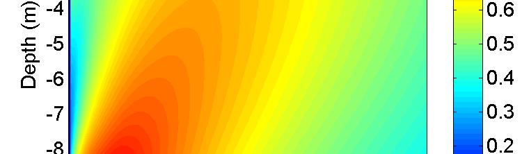
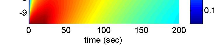
17 dissipated volume of water from this layer is pumped to the upper layers and result is some dilation (increase in void ratio) in the these layers for some time after the end of shaking. By the time this pumped volume of water in the upper layers dissipates all the layers show a consolidation response. In other words in the layered soil column pumping of water causes initial loosening of soil in the upper layers, which is then followed by densification. Finally Fig. 19 shows propagation of the horizontal acceleration through the soil column during shaking. In the uniform soil column Fig. 19a shows that the base acceleration is transmitted to the surface of the soil column. It shows some spikes of acceleration with large amplitude at the surface of the soil resulting from the dilative phases of soil response during the shaking phase. In the layered soil column, however, Fig. 19b shows that only the first cycle of shaking is transmitted to the surface (although with reduced amplitude) and subsequently the upper layers are isolated because of the fully liquefied state of the loose layer in element 1, E1. The transmitted accelerations to the surface of the soil column after the first cycle of shaking have very small amplitudes. 4.2 Example 2: Earthquake-Induced Shear Deformations in Gentle Slopes A 1m gently inclined (1.5 ) column of saturated sand consisting of twenty u p U eight-node brick elements was considered subjected to a base shaking. In terms of initial densities two particular cases have been studied in this example. In the first, the soil column is assumed to be uniform with e =.7 (relatively dense, Dr 75%), while in the other case a similar soil column is considered which includes a relatively loose layer with e =.9 (Dr 25%) at depth 2.5m to 3.5m (Fig. 22). The boundary condition are exactly same as those presented in Example 1. The soil parameters and the other parameters related to the boundary value problem are also same as those in Example 1, and are given in Tables 2 (Toyoura sand) and 3. The permeability 17
18 is assumed to be isotropic and equal to k = 1 3 m/s. A static application of gravity analysis was performed before the base excitation. The resulting fluid hydrostatic pressures and soil stress states along the soil column serve as initial conditions for the subsequent dynamic analysis. The input acceleration time history (Fig. 22) is considered with a max =.2g and shaking lasts for about 8 seconds. The following three cases have been studied in this paper: I. Uniform soil profile with a max =.2g II. Layered soil profile with a max =.2g III. Layered soil profile with a max =.4g The predicted behavior for cases I, II and III in terms of the vertical effective stress, shear stress, shear strain, excess pore pressure ratio (R u ) and lateral displacement are presented and discussed in the rest of this section. The response is shown for selected elements along the soil profile (for positions of the elements refer to Fig. 22). In particular Figs. 23a, 24a and 25a show changes in the shear stress and vertical effective stress. Figs. 23b, 24b and 25b show changes in the shear stress and shear strain. Finally Figs. 23c, 24c and 25c show times histories of the excess pore pressure ratio, R u. Contours of excess pore pressure (R u ), shear strain, and lateral displacements in all depths vs. time are presented in parts d, e and f of Fig. 23, 24 and 25 for the above three cases. Note that R u = u e /(σ v ) in where u e is the excess pore pressure and (σ v ) in is the initial effective vertical stress. Clearly R u cannot be larger than 1 since u e (σ v ) in (in cohesionless soils the stress state cannot go to the tensile side, in which u e > (σ v ) in ). Typical mechanism of response observed in different elements during the shaking is explained in the following. Generally at the early stages of loading in a cycle the element shows a contractive response in shearing which is associated with an increase in excess pore pressure and a decrease in vertical effective stress and the stiffness (in particular the 18
19 shear stiffness). As loading continues to some larger stress-ratios the mechanism of response in the element might change to a dilative regime. This means that as shearing continues, the excess pore pressure decreases and the vertical effective stress and the soil stiffness increase. In other words soil regains its stiffness during the dilative phase. Upon and after reversal of shear stress increment again the sample shows a contractive regime with an increase in excess pore pressure and a decrease in vertical effective stress and soil stiffness. As the absolute value of stress-ratio exceeds a certain level (phase transformation) in the reverse loading (in negative stress-ratios) the element again shows the dilative response. The final stress-ratio increment reversal in the loading cycle is again associated with a contractive response. The above mechanisms typically happens in all cycles. The overall contractive response could be stronger or weaker than the dilative response depending on the state of soil, i.e. its void ratio and effective stress. For looser samples or at higher confining pressures the contractive response is more pronounced and therefore shearing at such states shows increase in excess pore pressure and decrease in vertical effective stress and stiffness. In denser samples or at lower confining pressures the response is the opposite. Fig. 23 shows detailed response of the soil profile in case I. Based on the previous general explanation the response starts with a contractive regime which results in decreasing the vertical effective stress and the stiffness, and increasing the excess pore pressure ratio. Since a relatively dense state is assumed for this analysis (e =.7, D r 75%) the soil has a general tendency of dilation as the stress-ratio exceeds the dilation line (phase transformation). On the other hand, the inclination of the soil column poses asymmetric horizontal shear stresses (toward the direction of inclination) during cycles of shaking. This essentially makes the sample more prone to dilation in the parts of shaking toward the the inclination direction (positive directions of shear stress and strain in this case) and the soil regains its stiffness and strength (σ v ) in the dilative parts of the loading cycle. The dilative tendency of response besides the offset shear stress in cyclic loading lead to asymmetric butterfly loops in stress space during the dilative and the subsequent intense contractive phases of 19
20 response. The asymmetric horizontal shear stresses also results in asymmetric shear strains which accumulate toward the inclination of the soil profile and create permanent horizontal displacements in this direction. The dilative phases lead to instantaneous drops in excess pore pressure ratio R u. These drops are more pronounced in upper elements which have lower confining pressures and therefore have stronger dilative tendency. Fig. 24 shows response of the soil profile in case II. In this case presence of the relatively loose layer at depth m (e =.9, D r 25%) affects the response of the system. This layer has stronger contractive response in cycles of loading. Such tendency causes faster increase in excess pore pressure and decrease in vertical effective stress and stiffness. Degradation of stiffness leads to faster accumulation of the permanent shear strain in the symmetric loops of stress strain. The time histories of surface lateral displacement for these two cases are shows in Fig. 26 (presented results of case III in this figure will be discussed later). It can be observed that the permanent surface lateral displacement in case II (.4m) is almost twice as much as case I (.19m) due to presence of the relatively loose layer. The excess pore pressure ratio in the loose layers shows instantaneous spikes to R u = 1 and drops mainly to two values of.35 or.65 which are related to the end of dilative phases in positive and negative shear stresses, respectively. The expelled pore water from this layer during shaking is pumped to the upper layers and shows a considerable increase in the excess pore pressure ratio of element 19 (E19) after the end of shaking. Fig. 25 shows response of the soil profile in case III. The geometry and parameters in case III are the same as those in case II. The only difference is the intensity of the input base acceleration which is.4g in case III. The interesting observation in the simulation results is that although the magnitude of the base acceleration in case III is twice as much as case II, the calculated residual shear strains are not considerably different in the two cases. This could be attributed to the fact that in case III the larger amplitude of acceleration 2
21 (and shear stress) soon brings the soil state to the dilative phase during which the vertical effective stress increases and soil regains its strength. Comparing the stress path of element 3 (E3) in cases II and III makes this phenomena more clear. Due to increase of the vertical effective stress during the intense dilation in case III the effective stress state remains larger in this case compared to case II and therefore less degradation is observed in the subsequent cycles of loading. The strongly pronounced dilative response in all layers of soil profile in case III clearly affects the resulting excess pore pressure ratios (Fig. 25c) comparing to what was observed in case II (Fig. 24c). More specifically, case III experiences more intense drops in plots of R u even to negative values, specially at upper elements in which are even more dilative due to lower surcharge (confining pressure). The time histories of the surface lateral displacement, and variations with depth of the permanent lateral displacement for different cases are presented and compared in Fig. 26. Although case III shows larger amplitudes of cyclic motions, its permanent surface lateral displacement is about 2% smaller than case II. That is quite interesting, and make for the importance of interaction of dynamic characteristics of the earthquake and the response of the soil (and its components) as described by the SANISAND constitutive model. Fig. 26b provides more detailed information about the lateral displacements of soil layers in different cases. Due to the aforementioned stronger dilative response in case III, the dense layers adjacent to the loose layer appear to get stronger in case III and show lesser lateral displacements. This could also be considered as a part of the reason for smaller surface lateral displacement in case III compared to case II. Note that the permanent displacement is equivalent to integration of shear strains in the whole soil column. 21
22 5 SUMMARY AND CONCLUSIONS An efficient finite element formulation and a numerical tool for analysis of wave propagation phenomena in fluid saturated porous media has been developed. The saturated porous medium is modeled as a two phase, fully coupled system consisting of a porous solid and a fluid phase. The numerical tool includes the u p U formulation for fully coupled behavior of soils and the SANISAND model as an advanced elastic plastic constitutive model for modeling of stress-strain response of the solid phase. The formulation takes into account velocity proportional damping (usually called viscous damping) by proper modeling of coupling of pore fluid and solid skeleton, while the displacement proportional damping is appropriately modeled by the dissipation mechanism of the constitutive model of elasto plasticity used. Numerical results which demonstrate the accuracy and versatility of the formulations and capabilities of the model were presented. The verified and validated models and computational simulations tool are then used to predict behavior of layered soil system during seismic loading. Two general problems have been studied. Firstly, a numerical study has been conducted on isolating effects of a liquefied sand layer in propagation of seismic waves. Secondly, seismically induced shear deformation of a gentle slope in the presence or absence of liquefiable layer has been studied as well. Attention was given to propagation of shear waves through soil layers, as well as to variation of stresses and strains during such propagation. Spatial evolution of liquefaction in loose and medium dense soil layers was also investigated. In the first example it was shown that liquefaction of loose layers in depth prevents transmission of earthquake-induced motions and shear stresses to the upper layers. While prevention of transmission of motions may be considered as a positive feature, the water flux coming from the liquefied bottom layers might force the upper layers towards lower effective stress and possibly instability even in absence of earthquake-induced shear stresses. More importantly, attention needs to be paid to the fact that liquefaction of the 22
23 deep loose layers could result in large strains in these layers which might result in (rigid block) translation of the upper layers. The second example was used to present complexities arising from variation of soil density in a layered system as well as the input base acceleration. For example, it is shown that larger shaking produces smaller lateral spread, because of close interaction of earthquake loading and soil constitutive response (with its solid and fluid components). In addition to demonstrating the capabilities of the u p U element, the SANISAND constitutive model and the nonlinear dynamic finite element numerical tool to handle complex phenomena, these studies provided new insight into the mechanisms of wave propagation and seismic behavior of saturated soil systems. Fully coupled nonlinear dynamic numerical simulations provide accurate means for detailed investigation on complex loading conditions and geometries and different material states. Such high fidelity simulations provide detailed input to PBD methods that most existing empirical approaches used in liquefaction modeling fail to provide. In particular one must emphasize the importance of using a robust and realistic constitutive model such as SANISAND which can account for the various important features of the soil response in relation to its density and loading conditions. For example it is important that the same constitutive model can show dilative or contractive response depending on the value of the state parameter ψ on which the peak stress ratio, and by consequence the plastic modulus, as well as the dilatancy stress ratio (phase transformation stress ratio), and by consequence the dilatancy, depend, as a result of the underlying bounding surface plasticity formulation. Similarly the capability to account for intense contractive response upon reverse loading increments after a dilative phase of loading, is realistically captured by the fabric dilatancy tensor and has an immediate effect on the predicted displacement and pore water pressure built up during cyclic loading. Had these constitutive propertied not been realistically described, the overall description of the phenomenon would have been much poorer to say the least. 23
24 Table 1 Simulation parameters used for the shock wave propagation verification problem. Parameter Symbol Value Poisson ratio ν.3 Young s modulus E kn/m 2 Solid particle bulk modulus K s kn/m 2 Fluid bulk modulus K f kn/m 2 Solid density ρ s 27 kg/m 3 Fluid density ρ f 1 kg/m 3 Porosity n.4 HHT parameter α -.2 Table 2 Material parameters of the SANISAND constitutive model for three types of sands. Parameter Symbol Toyoura Nevada Sacramento Elasticity G ν CSL M c e λ ξ Dilatancy n d A Kinematic n b Hardening h c h Fabric dilatancy z max c z 6 8 Table 3 Parameters used in the boundary value problem simulations (in addition to the material model parameters). Parameter Symbol Value Solid particle bulk modulus K s kn/m 2 Fluid bulk modulus K f kn/m 2 Solid density ρ s 27 kg/m 3 Fluid density ρ f 1 kg/m 3 HHT parameter α
25 Reality Analysis Model Discovery and Building Model Validation Computer Simulation Mathematical Model Continuum Mathematics Programming Computer Implementation Discrete Mathematics Code Verification Fig. 1. Schematic description of Verification and Validation procedures and the computational solution (after [37, 28]). Fig. 2. Viscous coupling finite-element analysis of infinite half-space subjected at the surface to a step displacement boundary condition. Solid Displ. (x1 3 cm) K=1 6 cm/s K=1 2 cm/s time (µsec) Fluid Displ. (x1 3 cm) K=1 2 cm/s K=1 6 cm/s Lines: Closed form Symbols: FEM time (µsec) Fig. 3. Compressional wave in both solid and fluid, comparison with closed form solution. 25
26 25 1q(1+e)/[3(p at p) 1/2 (2.97 e) 2 ] G o = Deviatoric strain, (%) Fig. 4. Calibration of the G constant using monotonic triaxial tests on Toyoura sand [31]. q (kpa) CIUC after shearing CIDC after shearing M=(q/p) critical =1.25 Void ratio, e e c = (p/p at ).7 CIUC initial CIUC after shearing CIDC initial CIDC after shearing p (kpa) (a) (p/p ).7 at (b) Fig. 5. Calibration of the CSL constants using monotonic triaxial tests on Toyoura sand [31]. 26
27 .2.1 ln(m/ η b ).4 n b =1.25 ln(η d /M).2 n d = ψ b (a) ψ d (b) A =.7 A =.2 p in =1 kpa 3 2 e=.833, D r =37.9% A =.2 q (kpa) A =2. q (kpa) 1 A =.7 A = Void ratio, e (c) p (kpa) 1.6 (d) h o (1 c h e)= e= (1.968e) q (kpa) 8.6 h o (1 c h e).8 h o =7.5 c h = e= Axial strain (%) (e) Void ratio, e (f) Fig. 6. Calibration of the bounding and dilatancy surface constants using monotonic triaxial tests on Toyoura sand [31]. 27
28 4 3 q (kpa) 2 1 z max =2 z max = p (kpa) Fig. 7. Calibration of the z max parameter using the loading unloading triaxial tests on Toyoura sand [31]. 28
29 Experiment Simulation q (kpa) 9 6 p in =5 kpa p in =1 kpa q (kpa) 9 6 p in =5 kpa p in =1 kpa Axial strain (%) (a) Axial strain (%) (b) 12 p in =5 kpa p in =1 kpa 12 p in =5 kpa p in =1 kpa 9 9 q (kpa) 6 q (kpa) Void ratio, e Void ratio, e (c) (d) Fig. 8. Simulations versus experiments in drained triaxial compression tests on isotropically consolidated samples of Toyoura sand [31]. 29
30 Experiment Simulation 4 4 q (kpa) 3 2 e=.735, D r =63.7% e=.833, D r =37.9% e=.97, D r =18.5% q (kpa) 3 2 e=.735, D r =63.7% e=.833, D r =37.9% e=.97, D r =18.5% Axial strain (%) (a) Axial strain (%) (b) 4 3 e=.735, D r =63.7% e=.833, D r =37.9% e=.97, D r =18.5% 4 3 e=.735, D r =63.7% e=.833, D r =37.9% e=.97, D r =18.5% q (kpa) 2 q (kpa) , 2, 3, p (kpa) p (kpa) (c) (d) Fig. 9. Simulations versus experiments in undrained triaxial compression tests on isotropically consolidated samples of Toyoura sand [31]. 3
31 Experiment Simulation 2 p=1 kpa (const.) 2 p=1 kpa (const.) e in =.845 e in =.845 Stress ratio, q/p 1 Stress ratio, q/p Shear strain, γ (%) Shear strain, γ (%) (a) (b) Volumetric strain, ε v (%) Volumetric strain, ε v (%) Shear strain, γ (%) Shear strain, γ (%) (c) (d) Volumetric strain, ε v (%) Volumetric strain, ε v (%) Stress ratio, q/p Stress ratio, q/p (e) (f) Fig. 1. Simulations versus experiments in constant-p cyclic triaxial tests on a relatively loose sample of Toyoura sand [32]. 31
32 Experiment Simulation Stress ratio, q/p 2 1 p=1 kpa (const.) e in =.653 Stress ratio, q/p 2 1 p=1 kpa (const.) e in = Shear strain, γ (%) Shear strain, γ (%) (a) (b).6.6 Volumetric strain, ε v (%).3.3 Volumetric strain, ε v (%) Shear strain, γ (%) Shear strain, γ (%) (c) (d).6.6 Volumetric strain, ε v (%).3.3 Volumetric strain, ε v (%) Stress ratio, q/p Stress ratio, q/p (e) (f) Fig. 11. Simulations versus experiments in constant-p cyclic triaxial tests on a relatively dense sample of Toyoura sand [32]. 32
33 q (kpa) Dr=6% 4% 6% 4% 6% 4% p=16 kpa p=8 kpa p=4 kpa Axial strain (%) (a) Volumetric strain (%) Dr=4% p=16 kpa 8 4 p=16 kpa Dr=6% Axial strain (%) (b) Fig. 12. Simulations (solid lines) versus experiments (symbols) in constant-p triaxial compression tests on isotropically consolidated samples of Nevada sand [33]. 33
34 Experiment Simulation q (kpa) 2 q (kpa) p (kpa) (a) p (kpa) (b) q (kpa) 2 q (kpa) Axial strain (%) (c) Axial strain (%) (d) Fig. 13. Simulations versus experiments in undrained cyclic triaxial tests on Nevada sand with D r 4% [33]. 34
35 q (kpa) Loose Dense p in =124 kpa Axial strain (%) (a) Volumetric strain (%) Loose Dense p in =124 kpa Axial strain (%) (b) Fig. 14. Simulations (solid lines) versus experiments (symbols) in drained triaxial compression tests on isotropically consolidated loose and dense samples of Sacramento river sand [34]. 35
36 loose (e=.96,.875) medium dense (e=.8) medium dense (e=.8) Fig. 15. Illustration of the problem in Example 1 in terms of the soil layering, the finite element mesh, and the input base acceleration. 36
37 2 2 E19 E E17 E E15 E E13 E13 σ xz (kpa) E11 σ xz (kpa) E11 E9 E E7 E E5 E E3 E E1 E σ (kpa) z σ (kpa) z (a) Uniform (b) Layered Fig. 16. Variation of shear stress σ xz vs vertical effective stress σ z for Elements E1 E19 during and after shaking. 37
38 2 2 E19 E E17 E E15 E E13 E13 σ xz (kpa) E11 σ xz (kpa) E11 E9 E E7 E E5 E E3 E E1 E γ (%) γ (%) (a) Uniform (b) Layered Fig. 17. Variation of shear stress σ xz vs shear strain γ for Elements E1 E19 during and after shaking. 38
39 E E E E E E E E13 void ratio E11 void ratio E E E E E E E E E E E time (sec) time (sec) (a) Uniform (b) Layered Fig. 18. Variation with time of void ratio e for Elements E1 E19 during and after shaking. 39
40 .5.5 z=1m z=1m z=9m z=9m z=8m z=8m z=7m z=7m z=6m z=6m a u,x (g) z=5m a u,x (g) z=5m z=4m z=4m z=3m z=3m z=2m z=2m z=1m z=1m z=m z=m time (sec) time (sec) (a) Uniform (b) Layered Fig. 19. Time history of horizontal component of acceleration in solid part of the mixture a u,x for nodes at different elevations during shaking. 4


41 (a) Uniform (b) Layered Fig. 2. Contours of Excess Pore Pressure (kpa) in the soil column at different times. (a) Uniform (b) Layered Fig. 21. Contours of Excess Pore Pressure Ratio (R u ) in the soil column at different times. 41

42 Fig. 22. Illustration of the problem in Example 2 in terms of the soil layering, the finite element mesh, and the input base acceleration. 42
 5 5 5 5 E11 σ xz (kpa) 5 5 5 5 E11 R u 1.5 1 E15 E11 E7 E7.")
 z (a) 5 5 5 1 15 2 γ (%) (b) E3 3 6 9 12 15 time (sec)")

 shear stress vs. vertical effective stress, (b) shear stress vs.")
43 5 5 1 E19 E E19 E15 E15.5 σ xz (kpa) E11 σ xz (kpa) E11 R u E15 E11 E7 E E7 E3 E σ (kpa) z (a) γ (%) (b) E time (sec) (c) (d) (e) (f) Fig. 23. Results of response of the uniform soil column with a max =.2g (case I) in selected elements along soil profile (E3, E7, E11, E13, E19): (a) shear stress vs. vertical effective stress, (b) shear stress vs. shear strain, (c) excess pore pressure ratio histories, (d) excess pore pressure ratio vs. time and depth, (e) shear strain vs. time and depth, (f) lateral displacement vs. time and depth. 43


 shear stress vs.")
44 5 5 1 E19 E E19 E15 E15.5 σ xz (kpa) E11 σ xz (kpa) E11 R u E15 E11 E7 E E7 E3 E σ (kpa) z (a) γ (%) (b) E time (sec) (c) (d) (e) (f) Fig. 24. Results of response of the layered soil column with a max =.2g (case II) in selected elements along soil profile (E3, E7, E11, E13, E19): (a) shear stress vs. vertical effective stress, (b) shear stress vs. shear strain, (c) excess pore pressure ratio histories, (d) excess pore pressure ratio vs. time and depth, (e) shear strain vs. time and depth, (f) lateral displacement vs. time and depth. 44
 z (a) 5 5 5 1 15 2 γ (%) (b) E3 3 6 9 12 15 time (sec) (c) (d) (e) (f) Fig. 25.")
 in selected elements along soil profile (E3, E7, E11, E13, E19): (a) shear stress vs. vertical effective stress, (b) shear stress vs.")
45 5 5 1 E19 E E19 E15 E15.5 σ xz (kpa) E11 σ xz (kpa) E11 R u E15 E11 E7 E E7 E3 E σ (kpa) z (a) γ (%) (b) E time (sec) (c) (d) (e) (f) Fig. 25. Results of response of the layered soil column with a max =.4g (case III) in selected elements along soil profile (E3, E7, E11, E13, E19): (a) shear stress vs. vertical effective stress, (b) shear stress vs. shear strain, (c) excess pore pressure ratio histories, (d) excess pore pressure ratio vs. time and depth, (e) shear strain vs. time and depth, (f) lateral displacement vs. time and depth. 45
Numerical Simulation of Fully Saturated Porous Materials
 INTERNATIONAL JOURNAL FOR NUMERICAL AND ANALYTICAL METHODS IN GEOMECHANICS Numerical Simulation of Fully Saturated Porous Materials Boris Jeremić ( ) 1, Zhao Cheng ( ) 2 3 (مهدی طيبات ( Taiebat Mahdi and
Finite Deformation Analysis of Dynamic Behavior of Embankment on Liquefiable Sand Deposit Considering Pore Water Flow and Migration
 6 th International Conference on Earthquake Geotechnical Engineering 1-4 November 215 Christchurch, New Zealand Finite Deformation Analysis of Dynamic Behavior of Embankment on Liquefiable Sand Deposit
Multiaxial Constitutive and Numerical Modeling in Geo-mechanics within Critical State Theory
 . THE UNIVERSITY OF BRITISH COLUMBIA Multiaxial Constitutive and Numerical Modeling in Geo-mechanics within Critical State Theory Mahdi Taiebat and Yannis F. Dafalias 2 Associate Professor, Department
FINITE ELEMENT SIMULATION OF RETROGRESSIVE FAILURE OF SUBMARINE SLOPES
 FINITE ELEMENT SIMULATION OF RETROGRESSIVE FAILURE OF SUBMARINE SLOPES A. AZIZIAN & R. POPESCU Faculty of Engineering & Applied Science, Memorial University, St. John s, Newfoundland, Canada A1B 3X5 Abstract
TIME-DEPENDENT BEHAVIOR OF PILE UNDER LATERAL LOAD USING THE BOUNDING SURFACE MODEL
 TIME-DEPENDENT BEHAVIOR OF PILE UNDER LATERAL LOAD USING THE BOUNDING SURFACE MODEL Qassun S. Mohammed Shafiqu and Maarib M. Ahmed Al-Sammaraey Department of Civil Engineering, Nahrain University, Iraq
Numerical model comparison on deformation behavior of a TSF embankment subjected to earthquake loading
 Numerical model comparison on deformation behavior of a TSF embankment subjected to earthquake loading Jorge Castillo, Yong-Beom Lee Ausenco, USA Aurelian C. Trandafir Fugro GeoConsulting Inc., USA ABSTRACT
Numerical simulation of inclined piles in liquefiable soils
 Proc. 20 th NZGS Geotechnical Symposium. Eds. GJ Alexander & CY Chin, Napier Y Wang & R P Orense Department of Civil and Environmental Engineering, University of Auckland, NZ. ywan833@aucklanduni.ac.nz
FROM THEORY TO PRACTICE IN GEOTECHNICAL ENGINEERING: THE MISSING LINKS. Yannis F. Dafalias
 FROM THEORY TO PRACTICE IN GEOTECHNICAL ENGINEERING: THE MISSING LINKS Yannis F. Dafalias Department of Civil and Environmental Engineering, University of California at Davis, & Department of Mechanics,
Drained Against Undrained Behaviour of Sand
 Archives of Hydro-Engineering and Environmental Mechanics Vol. 54 (2007), No. 3, pp. 207 222 IBW PAN, ISSN 1231 3726 Drained Against Undrained Behaviour of Sand Andrzej Sawicki, Waldemar Świdziński Institute
Prediction of torsion shear tests based on results from triaxial compression tests
 Prediction of torsion shear tests based on results from triaxial compression tests P.L. Smith 1 and N. Jones *2 1 Catholic University of America, Washington, USA 2 Geo, Lyngby, Denmark * Corresponding
2D Liquefaction Analysis for Bridge Abutment
 D Liquefaction Analysis for Bridge Abutment Tutorial by Angel Francisco Martinez Integrated Solver Optimized for the next generation 64-bit platform Finite Element Solutions for Geotechnical Engineering
The Role of Slope Geometry on Flowslide Occurrence
 American Journal of Environmental Sciences 3 (3): 93-97, 27 ISSN 1553-345X 27 Science Publications Corresponding Author: The Role of Slope Geometry on Flowslide Occurrence Chiara Deangeli DITAG, Politecnico
Analytical and Numerical Investigations on the Vertical Seismic Site Response
 Analytical and Numerical Investigations on the Vertical Seismic Site Response Bo Han, Lidija Zdravković, Stavroula Kontoe Department of Civil and Environmental Engineering, Imperial College, London SW7
Advanced model for soft soils. Modified Cam-Clay (MCC)
") Advanced model for soft soils. Modified Cam-Clay (MCC) c ZACE Services Ltd August 2011 1 / 62 2 / 62 MCC: Yield surface F (σ,p c ) = q 2 + M 2 c r 2 (θ) p (p p c ) = 0 Compression meridian Θ = +π/6 -σ
Advanced model for soft soils. Modified Cam-Clay (MCC) c ZACE Services Ltd August 2011 1 / 62 2 / 62 MCC: Yield surface F (σ,p c ) = q 2 + M 2 c r 2 (θ) p (p p c ) = 0 Compression meridian Θ = +π/6 -σ
USER S MANUAL 1D Seismic Site Response Analysis Example University of California: San Diego August 30, 2017
 USER S MANUAL 1D Seismic Site Response Analysis Example http://www.soilquake.net/ucsdsoilmodels/ University of California: San Diego August 30, 2017 Table of Contents USER'S MANUAL TABLE OF CONTENTS Page
DYNAMIC ANALYSIS OF PILES IN SAND BASED ON SOIL-PILE INTERACTION
 October 1-17,, Beijing, China DYNAMIC ANALYSIS OF PILES IN SAND BASED ON SOIL-PILE INTERACTION Mohammad M. Ahmadi 1 and Mahdi Ehsani 1 Assistant Professor, Dept. of Civil Engineering, Geotechnical Group,
CHAPTER 6: ASSESSMENT OF A COMPREHENSIVE METHOD FOR PREDICTING PERFORMANCE
 CHAPTER 6: ASSESSMENT OF A COMPREHENSIVE METHOD FOR PREDICTING PERFORMANCE 6.1 Overview The analytical results presented in Chapter 5 demonstrate the difficulty of predicting the performance of an improved
Soil Properties - II
 Soil Properties - II Amit Prashant Indian Institute of Technology andhinagar Short Course on eotechnical Aspects of Earthquake Engineering 04 08 March, 2013 Seismic Waves Earthquake Rock Near the ground
NUMERICAL MODELING OF INSTABILITIES IN SAND
 NUMERICAL MODELING OF INSTABILITIES IN SAND KIRK ELLISON March 14, 2008 Advisor: Jose Andrade Masters Defense Outline of Presentation Randomized porosity in FEM simulations Liquefaction in FEM simulations
Endochronic model applied to earthfill dams with impervious core: design recommendation at seismic sites
 Proceedings of the 1st IASME / WSEAS International Conference on Geology and Seismology (GES'7), Portoroz, Slovenia, May 15-17, 27 51 Endochronic model applied to earthfill dams with impervious core: design
EVALUATION OF SITE CHARACTERISTICS IN LIQUEFIABLE SOILS
 4 th International Conference on Earthquake Geotechnical Engineering June 25-28, 27 Paper No. 1651 EVALUATION OF SITE CHARACTERISTICS IN LIQUEFIABLE SOILS Konstantinos TREVLOPOULOS 1, Nikolaos KLIMIS 2
Dynamic Analysis Contents - 1
 Dynamic Analysis Contents - 1 TABLE OF CONTENTS 1 DYNAMIC ANALYSIS 1.1 Overview... 1-1 1.2 Relation to Equivalent-Linear Methods... 1-2 1.2.1 Characteristics of the Equivalent-Linear Method... 1-2 1.2.2
MODELING GEOMATERIALS ACROSS SCALES JOSÉ E. ANDRADE DEPARTMENT OF CIVIL AND ENVIRONMENTAL ENGINEERING EPS SEMINAR SERIES MARCH 2008
 MODELING GEOMATERIALS ACROSS SCALES JOSÉ E. ANDRADE DEPARTMENT OF CIVIL AND ENVIRONMENTAL ENGINEERING EPS SEMINAR SERIES MARCH 2008 COLLABORATORS: DR XUXIN TU AND MR KIRK ELLISON THE ROADMAP MOTIVATION
Constitutive modelling of fabric anisotropy in sand
 Geomechanics from Micro to Macro Soga et al. (Eds) 2015 Taylor & Francis Group, London, ISBN 978-1-138-02707-7 Constitutive modelling of fabric anisotropy in sand Z.W. Gao School of Engineering, University
Numerical modeling of liquefaction effects: Development & initial applications of a sand plasticity model
 4 th IASPEI / IAEE International Symposium Santa Barbara, California, Aug 23-26, 2011 Numerical modeling of liquefaction effects: Development & initial applications of a sand plasticity model Ross W. Boulanger
Examining the Soil Responses during the Initiation of a Flow Landslide by Coupled Numerical Simulations
 The 2012 World Congress on Advances in Civil, Environmental, and Materials Research (ACEM 12) Seoul, Korea, August 26-30, 2012 Examining the Soil Responses during the Initiation of a Flow Landslide by
CENTRIFUGE MODELING OF PILE FOUNDATIONS SUBJECTED TO LIQUEFACTION-INDUCED LATERAL SPREADING IN SILTY SAND
 CENTRIFUGE MODELING OF PILE FOUNDATIONS SUBJECTED TO LIQUEFACTION-INDUCED LATERAL SPREADING IN SILTY SAND L. González 1, D. Lucas 2 and T. Abdoun 3 1 Assistant Professor, Dept. of Civil Engineering, University
13 th World Conference on Earthquake Engineering Vancouver, B.C., Canada August 1-6, 2004 Paper No. 3016
 13 th World Conference on Earthquake Engineering Vancouver, B.C., Canada August 1-6, 2004 Paper No. 3016 SOLUTIONS FOR MITIGATING SOIL LIQUEFACTION EFFECTS A NUMERICAL STUDUY AHMAD JAFARI MEHRABADI 1 AND
USER S MANUAL 1D Seismic Site Response Analysis Example University of California: San Diego August 30, 2017
 USER S MANUAL 1D Seismic Site Response Analysis Example http://www.soilquake.net/ucsdsoilmodels/ University of California: San Diego August 30, 2017 Table of Contents USER'S MANUAL TABLE OF CONTENTS Page
EFFECT OF SILT CONTENT ON THE UNDRAINED ANISOTROPIC BEHAVIOUR OF SAND IN CYCLIC LOADING
 4 th International Conference on Earthquake Geotechnical Engineering June 25-28, 2007 Paper No. 1506 EFFECT OF SILT CONTENT ON THE UNDRAINED ANISOTROPIC BEHAVIOUR OF SAND IN CYCLIC LOADING Hadi BAHADORI
Cyclic Behavior of Sand and Cyclic Triaxial Tests. Hsin-yu Shan Dept. of Civil Engineering National Chiao Tung University
 Cyclic Behavior of Sand and Cyclic Triaxial Tests Hsin-yu Shan Dept. of Civil Engineering National Chiao Tung University Causes of Pore Pressure Buildup due to Cyclic Stress Application Stress are due
Effect of embedment depth and stress anisotropy on expansion and contraction of cylindrical cavities
 Effect of embedment depth and stress anisotropy on expansion and contraction of cylindrical cavities Hany El Naggar, Ph.D., P. Eng. and M. Hesham El Naggar, Ph.D., P. Eng. Department of Civil Engineering
SOIL SHEAR STRENGTH. Prepared by: Dr. Hetty Muhammad Azril Fauziah Kassim Norafida
 SOIL SHEAR STRENGTH Prepared by: Dr. Hetty Muhammad Azril Fauziah Kassim Norafida What is shear strength Shear strength of a soil is the maximum internal resistance to applied shearing forces Why it is
8.1. What is meant by the shear strength of soils? Solution 8.1 Shear strength of a soil is its internal resistance to shearing stresses.
 8.1. What is meant by the shear strength of soils? Solution 8.1 Shear strength of a soil is its internal resistance to shearing stresses. 8.2. Some soils show a peak shear strength. Why and what type(s)
Improvement of a hypoplastic model to predict clay behaviour under undrained conditions
 Improvement of a hypoplastic model to predict clay behaviour under undrained conditions Mašín, D. and Herle, I. September 3, 27 Accepted for publication in Acta Geotechnica ABSTRACT A shortcoming of the
A Constitutive Framework for the Numerical Analysis of Organic Soils and Directionally Dependent Materials
 Dublin, October 2010 A Constitutive Framework for the Numerical Analysis of Organic Soils and Directionally Dependent Materials FracMan Technology Group Dr Mark Cottrell Presentation Outline Some Physical
Numerical analysis of effect of mitigation measures on seismic performance of a liquefiable tailings dam foundation
 Numerical analysis of effect of mitigation measures on seismic performance of a liquefiable tailings dam foundation Yong-Beom Lee, Jorge Castillo Ausenco, USA Aurelian C. Trandafir Fugro GeoConsulting
Module 3. DYNAMIC SOIL PROPERTIES (Lectures 10 to 16)
") Module 3 DYNAMIC SOIL PROPERTIES (Lectures 10 to 16) Lecture 15 Topics 3.6 STRESS-STRAIN BEHAVIOR OF CYCLICALLY LOADED SOILS 3.7 SOME BASIC ASPECTS OF PARTICULATE MATTER BEHAVIOR 3.8 EQUIVALENT LINEAR
Module 3 DYNAMIC SOIL PROPERTIES (Lectures 10 to 16) Lecture 15 Topics 3.6 STRESS-STRAIN BEHAVIOR OF CYCLICALLY LOADED SOILS 3.7 SOME BASIC ASPECTS OF PARTICULATE MATTER BEHAVIOR 3.8 EQUIVALENT LINEAR
NONLINEAR FINITE ELEMENT ANALYSIS OF DRILLED PIERS UNDER DYNAMIC AND STATIC AXIAL LOADING ABSTRACT
 Proceedings of the 8 th U.S. National Conference on Earthquake Engineering April 18-22, 2006, San Francisco, California, USA Paper No. 1452 NONLINEAR FINITE ELEMENT ANALYSIS OF DRILLED PIERS UNDER DYNAMIC
Intro to Soil Mechanics: the what, why & how. José E. Andrade, Caltech
 Intro to Soil Mechanics: the what, why & how José E. Andrade, Caltech The What? What is Soil Mechanics? erdbaumechanik The application of the laws of mechanics (physics) to soils as engineering materials
NUMERICAL ANALYSIS OF DAMAGE OF RIVER EMBANKMENT ON SOFT SOIL DEPOSIT DUE TO EARTHQUAKES WITH LONG DURATION TIME
 Proceedings of the International Symposium on Engineering Lessons Learned from the 2011 Great East Japan Earthquake, March 1-4, 2012, Tokyo, Japan NUMERICAL ANALYSIS OF DAMAGE OF RIVER EMBANKMENT ON SOFT
Liquefaction - principles
 Liquefaction - principles Consider a box of dry sand, subjected to cycles of shear strain. On initial loading, sand usually compacts and then dilates. On unloading, the sand follows a similar path to loading,
3-D Numerical simulation of shake-table tests on piles subjected to lateral spreading
 3-D Numerical simulation of shake-table tests on piles subjected to lateral spreading M. Cubrinovski 1, H. Sugita 2, K. Tokimatsu 3, M. Sato 4, K. Ishihara 5, Y. Tsukamoto 5, T. Kamata 5 1 Department of
Soil Behaviour in Earthquake Geotechnics
 Soil Behaviour in Earthquake Geotechnics KENJI ISHIHARA Department of Civil Engineering Science University of Tokyo This publication was supported by a generous donation from the Daido Life Foundation
3D and 2D Formulations of Incremental Stress-Strain Relations for Granular Soils
 Archives of Hydro-Engineering and Environmental Mechanics Vol. 55 (2008), No. 1 2, pp. 45 5 IBW PAN, ISSN 121 726 Technical Note D and 2D Formulations of Incremental Stress-Strain Relations for Granular
Liquefaction Potential Variations Influenced by Building Constructions
 Earth Science Research; Vol. 1, No. 2; 2012 ISSN 1927-0542 E-ISSN 1927-0550 Published by Canadian Center of Science and Education Liquefaction Potential Variations Influenced by Building Constructions
An Endochronic-based approach for simulating pore water pressure variation during liquefaction of sand
 Noname manuscript No. (will be inserted by the editor) An Endochronic-based approach for simulating pore water pressure variation during liquefaction of sand Ali Pak Mohammad Ali Iranmanesh the date of
EARTHQUAKE-INDUCED SETTLEMENT AS A RESULT OF DENSIFICATION, MEASURED IN LABORATORY TESTS
 13 th World Conference on Earthquake Engineering Vancouver, B.C., Canada August 1-6, 2004 Paper No. 3291 EARTHQUAKE-INDUCED SETTLEMENT AS A RESULT OF DENSIFICATION, MEASURED IN LABORATORY TESTS Constantine
Numerical Modelling of Dynamic Earth Force Transmission to Underground Structures
 Numerical Modelling of Dynamic Earth Force Transmission to Underground Structures N. Kodama Waseda Institute for Advanced Study, Waseda University, Japan K. Komiya Chiba Institute of Technology, Japan
Simplified mapping rule for bounding surface simulation of complex loading paths in granular materials
 University of Wollongong Research Online Faculty of Engineering and Information Sciences - Papers: Part A Faculty of Engineering and Information Sciences 2014 Simplified mapping rule for bounding surface
Determination of Dynamic p-y Curves for Pile Foundations Under Seismic Loading
 Determination of Dynamic p-y Curves for Pile Foundations Under Seismic Loading A. Rahmani, M. Taiebat, W.D. L. Finn, and C. E. Ventura Department of Civil Engineering, University of British Columbia, Vancouver,
USER S MANUAL. 1D Seismic Site Response Analysis Example. University of California: San Diego.
 USER S MANUAL 1D Seismic Site Response Analysis Example http://www.soilquake.net/ucsdsoilmodels/ University of California: San Diego August 2, 2017 Table of Contents USER'S MANUAL TABLE OF CONTENTS Page
Dynamic Soil Pressures on Embedded Retaining Walls: Predictive Capacity Under Varying Loading Frequencies
 6 th International Conference on Earthquake Geotechnical Engineering 1-4 November 2015 Christchurch, New Zealand Dynamic Soil Pressures on Embedded Retaining Walls: Predictive Capacity Under Varying Loading
Geotechnical Elements and Models in OpenSees
 Geotechnical Elements and Models in OpenSees Pedro Arduino University of Washington, Seattle OpenSees Days 2008, OpenSees User Workshop, Monday Sept 8, 2008 Type of Geotechnical Problems that can be solved
Numerical Assessment of the Influence of End Conditions on. Constitutive Behavior of Geomaterials
 Numerical Assessment of the Influence of End Conditions on Constitutive Behavior of Geomaterials Boris Jeremić 1 and Zhaohui Yang 2 and Stein Sture 3 ABSTRACT In this paper we investigate the behavior
Modelling Progressive Failure with MPM
 Modelling Progressive Failure with MPM A. Yerro, E. Alonso & N. Pinyol Department of Geotechnical Engineering and Geosciences, UPC, Barcelona, Spain ABSTRACT: In this work, the progressive failure phenomenon
UNDRAINED FLOW CHARACTERISTICS OF PARTIALLY SATURATED SANDY SOILS IN TRIAXIAL TESTS
 4 th International Conference on Earthquake Geotechnical Engineering June 25-28, 2007 Paper No. 1239 UNDRAINED FLOW CHARACTERISTICS OF PARTIALLY SATURATED SANDY SOILS IN TRIAXIAL TESTS Yoshimichi TSUKAMOTO
Table of Contents. Foreword... xiii Introduction... xv
 Foreword.... xiii Introduction.... xv Chapter 1. Controllability of Geotechnical Tests and their Relationship to the Instability of Soils... 1 Roberto NOVA 1.1. Introduction... 1 1.2. Load control... 2
Hypoplastic Cam-clay model
 Hypoplastic model David Mašín Charles University in Prague corresponence address: David Mašíın Charles University in Prague Faculty of Science Albertov 6 12843 Prague 2, Czech Republic E-mail: masin@natur.cuni.cz
Microscale Modeling of Carbonate Precipitation. ERC Team Members CBBG Faculty Narayanan Neithalath, ASU Edward Kavazanjian ASU
 Microscale Modeling of Carbonate Precipitation ERC Team Members CBBG Faculty Narayanan Neithalath, ASU Edward Kavazanjian ASU Graduate Students Pu Yang Other Research Staff Nasser Hamdan Project Goals
Applicability of Multi-spring Model Based on Finite Strain Theory to Seismic Behavior of Embankment on Liquefiable Sand Deposit
 Applicability of Multi-spring Model Based on Finite Strain Theory to Seismic Behavior of Embankment on Liquefiable Sand Deposit Kyohei Ueda Railway Technical Research Institute, Kokubunji, Tokyo, Japan
Prof. B V S Viswanadham, Department of Civil Engineering, IIT Bombay
 56 Module 4: Lecture 7 on Stress-strain relationship and Shear strength of soils Contents Stress state, Mohr s circle analysis and Pole, Principal stressspace, Stress pathsin p-q space; Mohr-Coulomb failure
the tests under simple shear condition (TSS), where the radial and circumferential strain increments were kept to be zero ( r = =0). In order to obtai
, where the radial and circumferential strain increments were kept to be zero ( r = =0). In order to obtai") Institute of Industrial Science, niversity of Tokyo Bulletin of ES, No. 4 (0) STESS-DILATANCY CHAACTEISTICS OF SAND IN DAINED CYLIC TOSIONAL SHEA TESTS Seto WAHYDI and Junichi KOSEKI ABSTACT: Stress-dilatancy
Institute of Industrial Science, niversity of Tokyo Bulletin of ES, No. 4 (0) STESS-DILATANCY CHAACTEISTICS OF SAND IN DAINED CYLIC TOSIONAL SHEA TESTS Seto WAHYDI and Junichi KOSEKI ABSTACT: Stress-dilatancy
file:///d /suhasini/suha/office/html2pdf/ _editable/slides/module%202/lecture%206/6.1/1.html[3/9/2012 4:09:25 PM]
![file:///d /suhasini/suha/office/html2pdf/ _editable/slides/module%202/lecture%206/6.1/1.html[3/9/2012 4:09:25 PM]](/thumbs/96/126781421.jpg "file:///d /suhasini/suha/office/html2pdf/ _editable/slides/module%202/lecture%206/6.1/1.html[3/9/2012 4:09:25 PM]") Objectives_template Objectives In this section you will learn the following Introduction Different Theories of Earth Pressure Lateral Earth Pressure For At Rest Condition Movement of the Wall Different
Objectives_template Objectives In this section you will learn the following Introduction Different Theories of Earth Pressure Lateral Earth Pressure For At Rest Condition Movement of the Wall Different
EFFECTS OF GROUND WATER ON SEISMIC RESPONSES OF BASIN
 EFFECTS OF GROUND WATER ON SEISMIC RESPONSES OF BASIN Huei-Tsyr CHEN And Jern-Chern HO 2 SUMMARY It has long been recognized that the local soil and geology conditions may affect significantly the nature
PLAXIS LIQUEFACTION MODEL UBC3D-PLM
 PLAXIS LIQUEFACTION MODEL UBC3D-PLM Alexandros Petalas Assistant Researcher, PLAXIS B.V Vahid Galavi Researcher, PLAXIS B.V May 30, 2012 Contents 1 Key Features of UBC3D 2 1.1 Yield Surfaces...........................
Application of pseudo-symmetric technique in dynamic analysis of concrete gravity dams
 Application of pseudo-symmetric technique in dynamic analysis of concrete gravity dams V. Lotfi Department of Civil and Environmental Engineering, Amirkabir University, Iran Abstract A new approach is
Theory of Shear Strength
 MAJ 1013 ADVANCED SOIL MECHANICS Theory of Shear Strength Prepared by, Dr. Hetty 1 Strength of different materials Steel Concrete Soil Tensile strength Compressive strength Shear strength Complex behavior
Recent Research on EPS Geofoam Seismic Buffers. Richard J. Bathurst and Saman Zarnani GeoEngineering Centre at Queen s-rmc Canada
 Recent Research on EPS Geofoam Seismic Buffers Richard J. Bathurst and Saman Zarnani GeoEngineering Centre at Queen s-rmc Canada What is a wall (SEISMIC) buffer? A compressible inclusion placed between
CPT Applications - Liquefaction 2
 CPT Applications - Liquefaction 2 Peter K. Robertson CPT in Geotechnical Practice Santiago, Chile July, 2014 Definitions of Liquefaction Cyclic (seismic) Liquefaction Zero effective stress (during cyclic
Role of hysteretic damping in the earthquake response of ground
 Earthquake Resistant Engineering Structures VIII 123 Role of hysteretic damping in the earthquake response of ground N. Yoshida Tohoku Gakuin University, Japan Abstract Parametric studies are carried out
Influences of material dilatancy and pore water pressure on stability factor of shallow tunnels
 Influences of material dilatancy and pore water pressure on stability factor of shallow tunnels YANG Xiao-li( ), HUANG Fu( ) School of Civil and Architectural Engineering, Central South University, Changsha
(Refer Slide Time: 02:18)
") Geology and Soil Mechanics Prof. P. Ghosh Department of Civil Engineering Indian Institute of Technology Kanpur Lecture 40 Shear Strength of Soil - C Keywords: Shear strength of soil, direct shear test,
Geology and Soil Mechanics Prof. P. Ghosh Department of Civil Engineering Indian Institute of Technology Kanpur Lecture 40 Shear Strength of Soil - C Keywords: Shear strength of soil, direct shear test,
2D Embankment and Slope Analysis (Numerical)
") 2D Embankment and Slope Analysis (Numerical) Page 1 2D Embankment and Slope Analysis (Numerical) Sunday, August 14, 2011 Reading Assignment Lecture Notes Other Materials FLAC Manual 1. 2. Homework Assignment
2D Embankment and Slope Analysis (Numerical) Page 1 2D Embankment and Slope Analysis (Numerical) Sunday, August 14, 2011 Reading Assignment Lecture Notes Other Materials FLAC Manual 1. 2. Homework Assignment
Geotechnical Modeling Issues
 Nonlinear Analysis of Viaducts and Overpasses Geotechnical Modeling Issues Steve Kramer Pedro Arduino Hyung-Suk Shin University of Washington The Problem Approach Soil Soil Soil Soil Soil Soil Soil Soil
MODELING OF CYCLIC MOBILITY AN ENERGY APPROACH
 4 th International Conference on Earthquake Geotechnical Engineering June 25-28, 2007 Paper No. 1317 MODELING OF CYCLIC MOBILITY AN ENERGY APPROACH Stanislav LENART 1 ABSTRACT Different researches show
Numerical Modeling of Interface Between Soil and Pile to Account for Loss of Contact during Seismic Excitation
 Numerical Modeling of Interface Between Soil and Pile to Account for Loss of Contact during Seismic Excitation P. Sushma Ph D Scholar, Earthquake Engineering Research Center, IIIT Hyderabad, Gachbowli,
A MODEL FOR COUPLED DYNAMIC ELASTO-PLASTIC ANALYSIS OF SOILS
 Journal of GeoEngineering, Vol. 7, No. 3, pp. 089-096, December 2012 Fattah et al.: A Model for Coupled Dynamic Elastic Plastic Analysis of Soils 89 A MODEL FOR COUPLED DYNAMIC ELASTO-PLASTIC ANALYSIS
CYCLIC LIQUEFACTION POTENTIAL OF LACUS- TRINE CARBONATE SILT FROM JULIAN ALPS
 CYCLIC LIQUEFACTION POTENTIAL OF LACUS- TRINE CARBONATE SILT FROM JULIAN ALPS BOJAN ŽLENDER and STANISLAV LENART About the authors Bojan Žlender University of Maribor, Faculty of Civil Engineering Smetanova
Effective stress analysis of pile foundations in liquefiable soil
 Effective stress analysis of pile foundations in liquefiable soil H. J. Bowen, M. Cubrinovski University of Canterbury, Christchurch, New Zealand. M. E. Jacka Tonkin and Taylor Ltd., Christchurch, New
LIQUEFACTION ASSESSMENT BY THE ENERGY METHOD THROUGH CENTRIFUGE MODELING
 LIQUEFACTION ASSESSMENT BY THE ENERGY METHOD THROUGH CENTRIFUGE MODELING Hesham M. Dief, Associate Professor, Civil Engineering Department, Zagazig University, Zagazig, Egypt J. Ludwig Figueroa, Professor
Evaluation of dynamic behavior of culverts and embankments through centrifuge model tests and a numerical analysis
 Computer Methods and Recent Advances in Geomechanics Oka, Murakami, Uzuoka & Kimoto (Eds.) 2015 Taylor & Francis Group, London, ISBN 978-1-138-00148-0 Evaluation of dynamic behavior of culverts and embankments
EFFECTS OF PLASTIC POTENTIAL ON THE HORIZONTAL STRESS IN ONE-DIMENSIONAL CONSOLIDATION
 Journal of GeoEngineering, Vol. 11, No. 1, pp. 27-31, April Iinuma 216 et al.: Effects of Plastic Potential on the Horizontal Stress in One-Dimensional Consolidation 27 http://dx.doi.org/1.631/jog.216.11(1).3
SEISMIC RESPONSE OF A SANDY STRATUM WITH A SILT LAYER UNDER STRONG GROUND MOTIONS
 SEISMIC RESPONSE OF A SANDY STRATUM WITH A SILT LAYER UNDER STRONG GROUND MOTIONS Bakhtiar Cahyandi Ridla 1), Huei-Tsyr Chen 2), M. Ruslin Anwar 3) 1) Double Degree Program E-mail: bakhtiar.ridla@gmail.com
Evaluation of soil liquefaction using the CPT Part 2
 Evaluation of soil liquefaction using the CPT Part 2 P.K. Robertson 2013 Definitions of Liquefaction Cyclic (seismic) Liquefaction Zero effective stress (during cyclic loading) Flow (static) Liquefaction
CONSOLIDATION BEHAVIOR OF PILES UNDER PURE LATERAL LOADINGS
 VOL., NO., DECEMBER 8 ISSN 89-8 -8 Asian Research Publishing Network (ARPN). All rights reserved. CONSOLIDATION BEAVIOR OF PILES UNDER PURE LATERAL LOADINGS Qassun S. Mohammed Shafiqu Department of Civil
INFLUENCE OF SOIL NONLINEARITY AND LIQUEFACTION ON DYNAMIC RESPONSE OF PILE GROUPS
 INFLUENCE OF SOIL NONLINEARITY AND LIQUEFACTION ON DYNAMIC RESPONSE OF PILE GROUPS Rajib Sarkar 1 and B.K. Maheshwari 2 1 Research Scholar, Dept. of Earthquake Engineering, IIT Roorkee, India, e-mail:
Analysis of soil failure modes using flume tests
 Analysis of soil failure modes using flume tests A. Spickermann & J.-P. Malet Institute of Earth Physics, CNRS UMR 751, University of Strasbourg, Strasbourg, France Th.W.J. van Asch, M.C.G. van Maarseveen,
Validation of empirical formulas to derive model parameters for sands
 Validation of empirical formulas to derive model parameters for sands R.B.J. Brinkgreve Geo-Engineering Section, Delft University of Technology, Delft, Netherlands/Plaxis B.V., Delft, Netherlands E. Engin
Discrete Element Modeling of Soils as Granular Materials
 Discrete Element Modeling of Soils as Granular Materials Matthew R. Kuhn Donald P. Shiley School of Engineering University of Portland National Science Foundation Grant No. NEESR-936408 Outline Discrete
Benefits of Collaboration between Centrifuge Modeling and Numerical Modeling. Xiangwu Zeng Case Western Reserve University, Cleveland, Ohio
 Benefits of Collaboration between Centrifuge Modeling and Numerical Modeling Xiangwu Zeng Case Western Reserve University, Cleveland, Ohio ABSTRACT There is little doubt that collaboration between centrifuge
Module 6 LIQUEFACTION (Lectures 27 to 32)
") Module 6 LIQUEFACTION (Lectures 27 to 32) Lecture 31 Topics 6.6 EFFECTS OF LIQUEFACTION 6.6.1 Alteration of Ground Motion 6.6.2 Development of Sand Boils 6.6.3 Settlement 6.6.4 Settlement of Dry Sands
Module 6 LIQUEFACTION (Lectures 27 to 32) Lecture 31 Topics 6.6 EFFECTS OF LIQUEFACTION 6.6.1 Alteration of Ground Motion 6.6.2 Development of Sand Boils 6.6.3 Settlement 6.6.4 Settlement of Dry Sands
APPENDIX I. Deformation Analysis of the Left Abutment
 APPENDIX I Deformation Analysis of the Left Abutment August 25, 2016 Appendix I Deformation Analysis of the Left Abutment TABLE OF CONTENTS I1 INTRODUCTION... 1 I2 MODEL DEVELOPMENT... 2 I2.1 General...
Stress and Strains in Soil and Rock. Hsin-yu Shan Dept. of Civil Engineering National Chiao Tung University
 Stress and Strains in Soil and Rock Hsin-yu Shan Dept. of Civil Engineering National Chiao Tung University Stress and Strain ε 1 1 2 ε 2 ε Dimension 1 2 0 ε ε ε 0 1 2 ε 1 1 2 ε 2 ε Plane Strain = 0 1 2
Bifurcation Analysis in Geomechanics
 Bifurcation Analysis in Geomechanics I. VARDOULAKIS Department of Engineering Science National Technical University of Athens Greece and J. SULEM Centre d'enseignement et de Recherche en Mecanique des
Monitoring of underground construction
 Monitoring of underground construction Geotechnical Aspects of Underground Construction in Soft Ground Yoo, Park, Kim & Ban (Eds) 2014 Korean Geotechnical Society, Seoul, Korea, ISBN 978-1-138-02700-8
LETTERS TO THE EDITOR
 NTERNATONAL JOURNAL FOR NUMERCAL AND ANALYTCAL METHODS N GEOMECHANCS, VOL. 13, 101-107 (1989) LETTERS TO THE EDTOR A LARGE STRAN THEORY AND TS APPLCATON N THE ANALYSS OF THE CONE PENETRATON MECHANSM (P.
NUMERICAL ANALYSIS OF GEO-STRUCTURES IN A LIQUEFACTION REGIME
 First European Conference on Earthquake Engineering and Seismology (a joint event of the 3 th ECEE & 3 th General Assembly of the ESC) Geneva, Switzerland, 3-8 September 26 Paper Number: 245 NUMERICAL
STUDY OF THE BEHAVIOR OF PILE GROUPS IN LIQUEFIED SOILS
 STUDY OF THE BEHAVIOR OF PILE GROUPS IN LIQUEFIED SOILS Shin-Tower Wang 1, Luis Vasquez 2, and Lymon C. Reese 3, Honorary Member,, ASCE ABSTRACT : 1&2 President & Project Manager, Ensoft, Inc. Email: ensoft@ensoftinc.com
Model tests and FE-modelling of dynamic soil-structure interaction
 Shock and Vibration 19 (2012) 1061 1069 1061 DOI 10.3233/SAV-2012-0712 IOS Press Model tests and FE-modelling of dynamic soil-structure interaction N. Kodama a, * and K. Komiya b a Waseda Institute for