Piedmont Chapter Vibration Institute Training Symposium 10 May, 2012 FIELD BALANCING OF ROTATING MACHINERY.
|
|
|
- Edgar Lyons
- 6 years ago
- Views:
Transcription


1 Piedmont Chapter Vibration Institute Training Symposium 10 May, 2012 FIELD BALANCING OF ROTATING MACHINERY
2 Presenter: William T. Pryor III Senior Technical Director PdM Solutions, Inc. Vibration Analyst Category IV Member VI Board of Directors
3 Presentation is going to concentrate on setting up and performing a single plane balance using Vector and Influence Coefficient methods: 1. Setting up for success 2. Trial Weight Selection 3. Trial Weight Placement 4. Single Plane Calculation
4 Is Balance the Problem Technique and Strategy Unusual Problems Mass Unbalance Force Rotor Classification Balancing Techniques Pre-balancing Checks Trial Weight Selection & Location Balancing Pitfalls Single Plane Balancing Two Plane Balancing Balance Limits Conclusions
5 Modern Techniques and Instrumentation Field Balancing an Indirect Process Analyst s Goals Beware of Black Boxes and Traps
6 Mass unbalance (heavy spot) cannot be measured directly High spot (angular location of peak or peak to peak vibration) is used to determine heavy spot Balancing is an art and science science in the vector procedures art in selection of balance planes, speeds, measurement locations as well as trial weight sizes and locations Balancing is a method of weight compensation to minimize vibration Global weights added to compensate for local unbalances can introduce stress
7 Is Balance the Problem? Beware of false indicators - Misalignment & Resonance Unbalance a Rotating Force Resonance and Flexible Structures Complicate the Picture
8 Vibration Transducer Once-Per-Revolution Sensor Filter capable of measuring Speed, Amplitude, and Phase Marker or Paint Stick Polar Graph Paper and Triangles Balance Weights and Scale
9 Rule #1 Keep it Simple Rule #2 Be Consistent Rule #3 Do not make up your own rules Rule #4 Remember the 1 st 3 rules
10 Before attempting to balance: Remember there are multiple reasons for a high 1X amplitude component. Perform a complete analysis prior to balancing to ensure that other mechanical faults are not the cause of the 1X response.
11 Misalignment Thermal Effects Product buildup on rotor Erosion or corrosion of rotor Bowed, bent, or eccentric shaft Bearing or seal wear Roller Deflection Paper Machines Machining errors/incorrect assembly Not properly balanced in shop Looseness in built-up rotor components
12 Not mass unbalance Loose supports Frame misalignment Stiffness asymmetry Inaccurate data Thermal sensitivity Resonance Unbalance distribution
13 1. The rotating component did not go out of balance by itself. 2. Remain skeptical during the balancing process and use the balancing procedure as a diagnostic tool. 3. If balance attempt is not working as anticipated STOP and THINK about what is going on. It may not be unbalance.
14 1) Number Fan Blades or Holes 0 to N. As an example: if there are 8 Blades, Blade 0 is also Blade 8 (0 to 360 Degrees). Blade # s will increase in sequence by turning the rotor in the direction of rotation. 2) Install Vibration measurement sensor Inline with Blade 0 3) Install Once-per Rev timing mark and sensor when Blade 0 is inline with measurement sensor. 4) Make a drawing showing blades, transducer placement, and angles. Remember angles increase against rotation. 5) Determine trial weight amount and have weight available.

15
16 When we balance a rotor there are 2 unknown factors which need to be determined in order to solve a rotor balance problem. 1) The amount of weight required 2) Angle of weight placement
17 Speed of the machine Radius of weight placement Rotor mode shape relative to balance plane selected Proximity to Rotor Balance Resonance (Critical Speed)
18 Balance trial weight selection should be based on 1 of the following: A: User experience with the same or like machine. B: Experience with similarly designed and constructed machine. C: In the absence of above, a trial weight is calculated to generate a centrifugal force equal to 10% of the rotors weight. Note: For rotors operating above 3600 some suggest that a calculation yielding 5% of the rotors weight should be used as an initial trial weight.
19 Centrifugal Force: C f = m r 2 C f = Centrifugal Force Lb f m = Mass of the rotor = Weight/Gravity = Lb/386.4 in/sec 2 Note 1 G = 32.2 Ft/Sec 2 = in/sec 2 r = Weight add radius in inches = Rotor speed in radians
20 Calculate the size of the trial weight needed for an electric AC motor operating at 1785 RPM. The rotor weighs 1800 pounds and the weight can be added to the rotor at a radius of 6 inches. The easiest way to treat this problem is to break it down into a couple of parts. 1 st we want our trial weight to generate a force equal to 10% of the rotor weight. So from our example: C f = 1800 Lb Rotor/10 = 180 #
21 2 nd Our weight add radius is 6 3 rd We need to calculate the speed of the rotor in radians RPM * 2 = 60 sec/min = [2 (29.75 Hz)] = [2* 3.14*29.75 Hz] = Radians/Sec Note: 1 Radian = 2 = 360 Degrees 2 = (186.83) 2 = ( * ) = Radians/Sec 2
22 Centrifugal Force: C f = m r 2 C f m = r 2 180# # m = (6 )( radians) = in/sec 2
(386.4 in/sec 2 ) W = 0.332 Lb W = 0.")
23 m = W/G solving for weight: W = M * G = ( #/in/sec 2 )(386.4 in/sec 2 ) W = Lb W = Lb * 16 Ounce/Lb = 5.3 Ounce
24 W W Nr T 2 where: W T = trial weight, oz. r = eccentricity of trial weight, in. W = static weight of rotor, lb. N = speed of rotor, RPM
25 Wt = (1800 #) = 5.3 Oz. (1785 RPM) 2 * 6 where: W T = trial weight, oz. r = eccentricity of trial weight, in. = 6 W = static weight of rotor, lb. = 1800# N = speed of rotor, RPM = 1785 RPM
26 Proximity to Rotor Balance Resonance (Critical Speed) (relationship of rotor high spot to heavy spot) Rotor mode shape
27 Vibration Institute Balance of Rotating Machines Initially the angular relationship of the Heavy Spot to the High Spot is unknown.
28 Vibration Institute Balance of Rotating Machines
29 Below resonance add At resonance add 90 0 Above resonance add 0 0 If unknown it is usually safe to add 90 0 Remember the purpose of a trial weight is to cause the rotor to display a reasonable amplitude and/or phase change compared to the initial unbalance run. An amplitude and/or phase change is required in order to perform the balancing calculation. An amplitude change of 10% or phase change of at least 15 0 is desired.
30


31
32
33
34
35
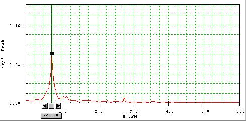
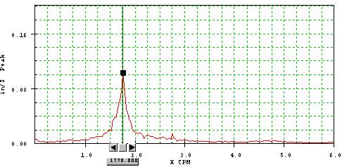
36 1. Acquire initial set of 1X amplitude and phase data. Note: Log 1X data in vertical, horizontal, and axial directions at both bearings. 2. Shut down machine and observe 1X amplitude and phase during shutdown to determine proximity of running speed to resonance. 3. Draw Initial 1X vector on Polar graph paper 4. Lock out machine.
37 5. Determine trial weight angular placement. Show trial weight magnitude and placement on polar graph. 6. Attach trial weight to rotor. 7. Release locks 8. Run machine and log 1X amplitude and phase at all locations. (Trial Run). 9. Shutdown machine and lock out equipment. 10.REMOVE TRIAL WEIGHT
38 11. Draw Trial Weight vector on polar graph. 12. Perform balance calculations to determine magnitude and angle of corrective weight. 13. Attach weight to machine. 14. Release locks and run equipment. 15. Log 1X amplitude and phase at all locations and evaluate data. Did 1X amplitudes decrease at all locations. If not, this may not be just a balance issue. Is a trim run required to reduce levels to desired magnitude.
39 16. For trim run use Sensitivity/Response Vector to calculate trim balance correction, lock out machine and repeat steps Note: If amplitudes do not decrease following trim balance it is probably not a mass unbalance problem. Review data!
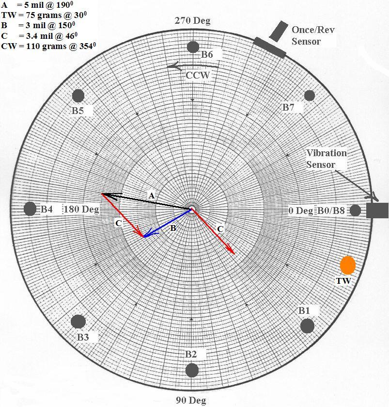
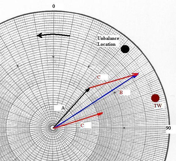
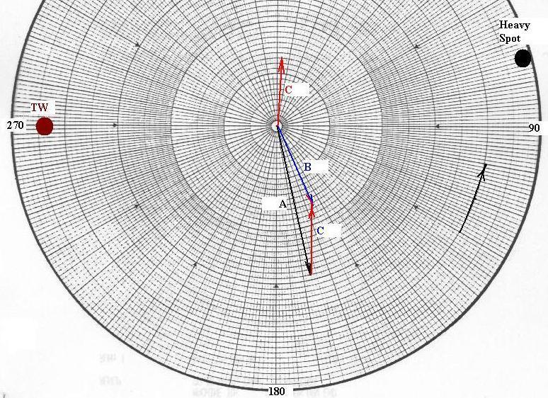
40 1. A = Initial Vibration Response ( Angle) 2. TW = Trial Weight Placement Angle) 3. B = Trial Weight Vector = A + Effect of Trial Weight Angle) 4. C = Trial Weight Effect = B - A (Draw a line from the head of the A to the head of the B vector. Measure the magnitude of C 5. Calculate the Rotor Sensitivity to weight = S = TW/C (Weight/Mil)
41 6. Calculate the Correction Weight = (Sensitivity) (Initial Response) 7. Measure the angle between C and A. (This is the number of degrees that weight must be rotated from Trial Weight location) 8. Draw arrow from C to A. (This is the direction to move final balance weight from trial weight location) 9. Show the final balance weight location on the polar graph. 10. Show location of rotor heavy spot on the graph.
42 11. Measure the angle (Lagging) from the Initial Vector (A) to the location of the installed Corrective Weight (CW). This is the angle of the Sensitivity Vector. The Corrective Weight is at the rotor Light Spot. 12. Combine this measured angle with the calculated rotor sensitivity to weight. Angle). This vector is the Rotor Sensitivity Vector. 13. Save the Sensitivity (S) Vector and use it for Trim and future balance jobs on this machine using the formula CW = S * A 1 where A 1 represents a newly measured initial unbalance vector.

43
44

45 Correction Weight = CW CW = Heavy Spot = U U =
46 Rotor Sensitivity = S S = Proof: CW = S * A 1 CW = ( )( ) CW =
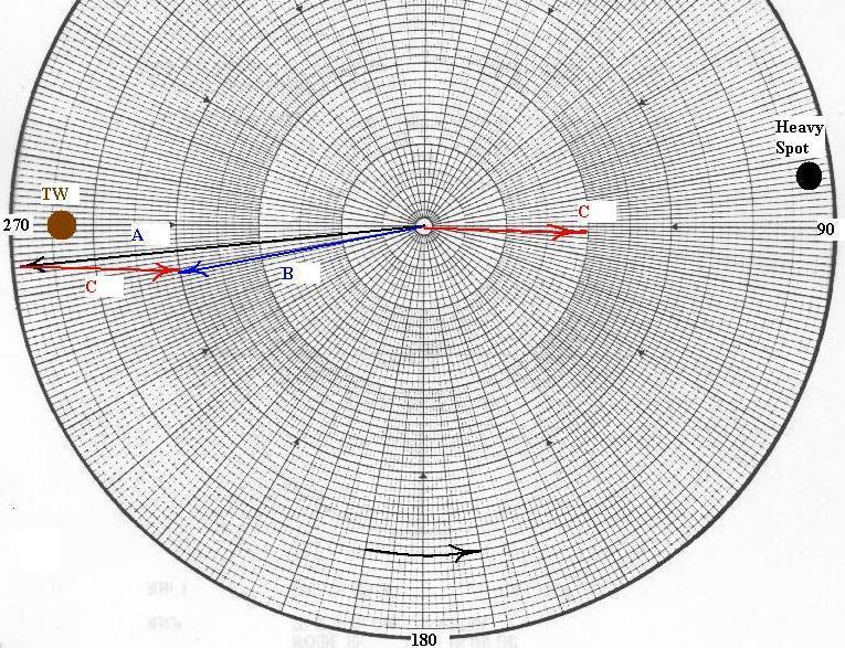
47 1. A = Initial Vibration Response ( Angle) 2. TW = Trial Weight Placement Angle) 3. B = Trial Weight Vector = A + Effect of Trial Weight Angle) 4. C = Trial Weight Effect = B - A (Draw a line from the head of the A to the head of the B vector. Measure the magnitude of C 5. Calculate the Unbalance Influence Coefficient R 11 = C Angle) Response at plane 1 to weight at plane 1 TW Angle)
48 6. Calculate the location of the Heavy Spot U 11 = Angle) Unbalance at Plane 1 R 11 Angle) 7. Weight Add Solution = U (Light Spot) 8. Show location of Heavy Spot and Light Spot on graph 9. Save Influence Coefficient for future balance work on this equipment
49
50

51
52 The Influence Coefficient provides powerful insight into a rotor behavior. 1. The influence Coefficient for a given rotor should not change over the life of the equipment. Changes in magnitude or angle indicate changes in rotor/support condition or may be the result of external forces such as misalignment. 2. The angle of the Influence Coefficient documents the relationship of the Rotor Heavy Spot (Force) to the Rotor High Spot. Hence, the angle documents where a rotor is running relative to its Critical Speed.
53 1) A = Initial Vibration Response ( ) 2) TW = Trial Weight Placement ( ) 3) B = A + Effect of Trial Weight ( ) 4) C = B A = Effect of Trial Weight ( ) 5) R 11 = = ) U 11 = = ) Weight Add Solution = U =
54
55 1) A = Initial Vibration Response ( ) 2) TW = Trial Weight Placement ( ) 3) B = A + Effect of Trial Weight ( ) 4) C = B A = Effect of Trial Weight ( ) 5) R 11 = = ) U 11 = = ) Weight Add Solution = U =
56
57 1) A = Initial Vibration Response ( ) 2) TW = Trial Weight Placement ( ) 3) B = A + Effect of Trial Weight ( ) 4) C = B A = Effect of Trial Weight ( ) 5) R 11 = = ) U 11 = = ) Weight Add Solution = U =
58
59
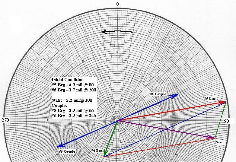
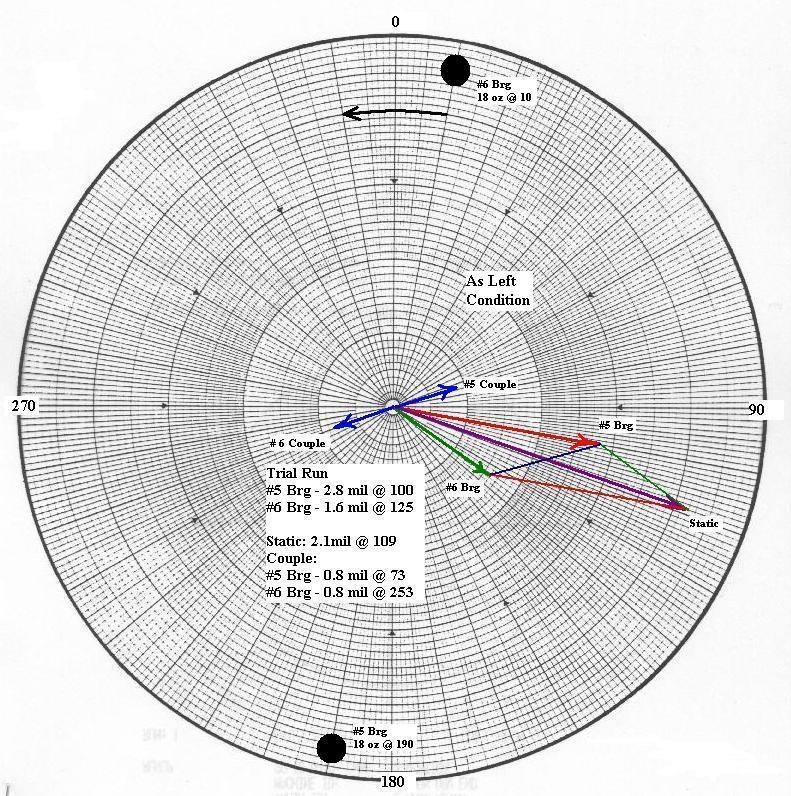
60 Based On #5 Bearing 1) A = Initial Vibration Response ( ) 2) TW = Trial Weight Placement ( ) 3) B = A + Effect of Trial Weight ( ) 4) C = B A = Effect of Trial Weight ( ) 5) R 11 = = ) U 11 = = ) Weight Add Solution = U = Brg # Brg #
61
62 Initial Unbalance A1 = S11 U1 + S12 U2 A2 = S21 U1 + S22 U2 A1 = Vibration Response at bearing #1 A2 = Vibration Response at bearing #2 U1 = Unbalance at Plane #1 U2 = Unbalance at Plane #2 S11 = Sensitivity of unbalance at Plane #1 to Location #1 S21 = Sensitivity of unbalance at Plane #1 to Location #2 S12 = Sensitivity of unbalance at Plane #2 to Location #1 S22 = Sensitivity of unbalance at Plane #2 to Location #2
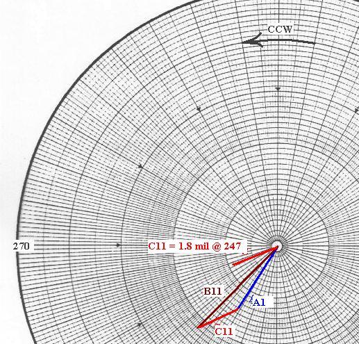
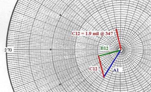
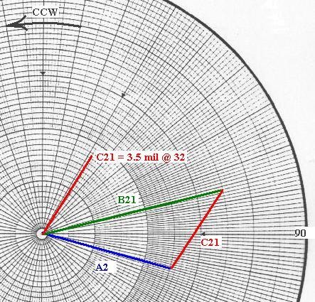
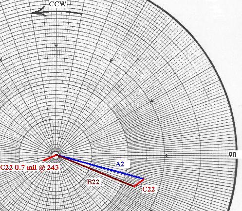
63 W1 = Trial weight at Plane #1 B11 = Vibration at Brg #1 with TW at Plane #1 B21 = Vibration at Brg #2 with TW at Plane #1 W2 = Trail weight at Plane #2 B12 = Vibration at Brg #1 with TW at Plane #2 B22 = Vibration at Brg #2 with TW at Plane #2
64 Effect of Trial Weights W1 and W2 at each measurement plane C11 = B11 A1 Response at Brg #1 to W1 C21 = B21 A2 Response at Brg #2 to W1 C12 = B12 A1 Response at Brg #1 to W2 C22 = B22 A2 Response at Brg #2 to W2 Calculate the Sensitivity (Influence Coefficient) S11 = C11 / W1 S21 = C21 / W1 S12 = C12 / W2 S22 = C22 / W2
65 Amount of unbalance at each plane U1 = (S22 A1 S12 A2) / (S22 S11 S12 S21) U2 = (S11 A2 S21 A1) / (S22 S11 S12 S21) Note: For weight add solution needs to be added to calculated unbalance vectors.
66 Balance Data
67
68
69
70
71 Calculated Solution: Plane 1 = Plane 2 =
72 Shop API ISO G1.0 Force Field
73 API /NAVY 4W oz in N
74 4W N NAVY/API U r = (oz.-in.) residual unbalance W = weight of rotor at journal, lb. N = speed of rotor, RPM U r = residual unbalance, oz.-in.
75 EXAMPLE: 1,000 lb. journal 6,000 RPM 4 1,000 U r = = oz.-in. 6, oz. in. e Pk = eccentricity = oz. 1,000 lb. x 16 in micro inches vibration Pk-Pk = 2 x e = 2 x = in. = mils Pk to Pk
76 ISO 1.0 mm/sec. = G1.0 (on the rotor not pedestal) e V Displacement 2 f Balancing machine limit ~ 20 micro inches
77 F F 1 10 Rotor WT 2 N Me 60 2
78 F = me 2 F = W b = U r = W 2 N e g 60 2 W 60 Ur g lb. in N g W oz. in. 2 N 2 2 G = in./sec. 2 W = rotor WT, lb. N = RPM of rotor
79 EXAMPLE: 2,000 lb 6,000 RPM WT per journal 1,000 lb. 60 Ur 1.6 x x 1, , Ur 1.57 oz. in. or Ur x 44.4 gm in. 16 2

80 Unbalance Tolerance Guide for Rigid Rotors* Based on VDI Standard by the Society of German Engineers, Oct *Reprinted from IRD Mechanalysis, Inc. Application Report No. 111, Dynamic Balancing


81 ROTOR CLASSIFICATION (Balance Quality) ROTOR DESCRIPTION (Example of General Types) G 40 G 16 G 6.3 G 2.5 G 1 Precision Balancing G 0.4 Ultra Precision Balancing Passenger car wheels and rims Automotive drive shafts Parts of crushing and agricultural machinery Drive shafts with special requirements, Rotor of processing machinery, Centrifuge bowls, Fans, Flywheels, Centrifugal pumps, General machinery and machine tool parts, Standard electric motor armatures Gas and steam turbines, Blowers, Turbine rotors, Turbo generators, Machine tool drives, Medium and bigger electric motor armature with special requirements, Armature of fractional hp motors, Pumps with turbine drive Jet engine and super charter rotors, tape recorder and phonograph drives, Grinding machine drives, Armatures of fractional HP motors with special requirements Armatures, shafts and precision grinding machines
82 T allowable vibration Vper x W x R where V per = mils pk to pk T = effect vector, mils pk to pk W t x R = trial wt (oz.) x radius (in.) G = ISO grade W = weight of rotor (lb.) N = Speed, RPM t GW N
83 Example Calculate the allowable vibration level for a fan. The fan operates at 1,800 RPM and weight 6,590 lb. A trial weight of 6.5 oz created an effect vector of 10 mils. Assume the radius of the balance weight is 40 inches and the ISO chart is used (G 6.3). V V per per 10 Mils x 6.3 x 6,590 x 6.5 x 40 1, mils pk to pk
Theory & Practice of Rotor Dynamics Prof. Rajiv Tiwari Department of Mechanical Engineering Indian Institute of Technology Guwahati
 Theory & Practice of Rotor Dynamics Prof. Rajiv Tiwari Department of Mechanical Engineering Indian Institute of Technology Guwahati Module - 8 Balancing Lecture - 1 Introduce To Rigid Rotor Balancing Till
SIMPLIFIED PREDICTION OF BALANCE SENSITIVITY
 1 SIMPLIFIED PREDICTION OF BALANCE SENSITIVITY Brian C. Howes, M.Sc., P.Eng. Scott G. Masterson, B.Sc. Beta Machinery Analysis Ltd. 300, 1615 10 Avenue S.W. Calgary, Alberta T3C 0J7 ABSTRACT It is possible
Mechanical Vibrations Prof. Rajiv Tiwari Department of Mechanical Engineering Indian Institute of Technology, Guwahati
 Mechanical Vibrations Prof. Rajiv Tiwari Department of Mechanical Engineering Indian Institute of Technology, Guwahati Module - 12 Signature analysis and preventive maintenance Lecture - 3 Field balancing
Advanced Field Single Plane Trim Balancing
 Advanced Field Single Plane Trim Balancing Alexander Ferrari, Qatar LNG Site Project Engineering Leader, GE Oil & Gas Florence, Italy alexander.ferrari@ge.com Paolo Battagli, Large LNG Engineering Project
SH O P BA L A N C I N G TO L E R A N C E S A PR A C T I C A L GU I D E
 B A L A N C I N G SH O P BA L A N C I N G TO L E R A N C E S A PR A C T I C A L GU I D E B Y E A R L M. H A L F E N Balanced scrawled in chalk across a rotor all too often goes unchallenged. Balance is
This Capstone Project will address the analysis and diagnosis of the Steam Turbo-Generator (STG) machine vibration problems in Thermal Power Plant
 machine vibration problems in Thermal Power Plant") This Capstone Project will address the analysis and diagnosis of the Steam Turbo-Generator (STG) machine vibration problems in Thermal Power Plant (TPP) Kosova-B that are degrading the normal operations
This Capstone Project will address the analysis and diagnosis of the Steam Turbo-Generator (STG) machine vibration problems in Thermal Power Plant (TPP) Kosova-B that are degrading the normal operations
Mechanical vibration Rotor balancing. Part 2: Vocabulary. Vibrations mécaniques Équilibrage des rotors Partie 2: Vocabulaire. First edition
 Provläsningsexemplar / Preview INTERNATIONAL STANDARD ISO 21940-2 First edition 2017-05 Mechanical vibration Rotor balancing Part 2: Vocabulary Vibrations mécaniques Équilibrage des rotors Partie 2: Vocabulaire
Field Balancing Experiences
 E:\Marketing Communications\Papers and Presentations\Technical Papers\New Technical Papers\Field Balancing Experiences#4.doc 1 Field Balancing Experiences By Brian Howes and Bryan Long Brian Howes is Manager
Unbalance Response and Field Balancing of an 1150-MW Turbine-Generator with Generator Bow
 Dyrobes Rotordynamics Software http://dyrobes.com 7 IFToMM-Conference on Rotor Dynamics, Vienna, Austria, 25-28 September 2006 Unbalance Response and Field Balancing of an 1150-MW Turbine-Generator wi
DYNAMIC BALANCING OF ROTATING MACHINERY EXPERIMENT
 DYNMIC LNCING OF OTTING MCHINEY EXPEIMENT Technical dvisor: Dr. K. Nisbett January 996 6. GENEL OJECTIVES ) To gain insight into the causes of undesirable vibration of rotors and to understand static and
SAMCEF For ROTORS. Chapter 1 : Physical Aspects of rotor dynamics. This document is the property of SAMTECH S.A. MEF A, Page 1
 SAMCEF For ROTORS Chapter 1 : Physical Aspects of rotor dynamics This document is the property of SAMTECH S.A. MEF 101-01-A, Page 1 Table of Contents rotor dynamics Introduction Rotating parts Gyroscopic
Dynamics of Machines Prof. Amitabha Ghosh Department of Mechanical Engineering Indian Institute of Technology, Kanpur
 Dynamics of Machines Prof. Amitabha Ghosh Department of Mechanical Engineering Indian Institute of Technology, Kanpur Module - 3 Lecture - 3 Balancing Machines and Field Balancing of Rotating Discs We
ABSOLUTE AND RELATIVE VIBRATION INCONSISTENCIES IN DYNAMIC ANALYSIS OF HIGH POWER TURBOGENERATOR ROTATING SYSTEM
 45 ABSOLUTE AND RELATIVE VIBRATION INCONSISTENCIES IN DYNAMIC ANALYSIS OF HIGH POWER TURBOGENERATOR ROTATING SYSTEM Vytautas BARZDAITIS*, Remigijus JONUŠAS*, Rimantas DIDŽIOKAS**, Vytautas BARZDAITIS V***.
ROTATING MACHINERY VIBRATION
 SECOND EDITION ROTATING MACHINERY VIBRATION From Analysis to Troubleshooting MAURICE L. ADAMS, JR Case Western Reserve University Cleveland, Ohio W^ C\ CRC Press У Taylor &. Francis Group Boca Raton London
Methods For Reducing Vibration (Intro to Vibration Control) Robert J. Sayer, PE President, The Vibration Institute Owner, Applied Structural Dynamics
 Robert J. Sayer, PE President, The Vibration Institute Owner, Applied Structural Dynamics") Methods For Reducing Vibration (Intro to Vibration Control) Robert J. Sayer, PE President, The Vibration Institute Owner, Applied Structural Dynamics 1 www.vi-institute.org Vibration & Machine Reliability
Methods For Reducing Vibration (Intro to Vibration Control) Robert J. Sayer, PE President, The Vibration Institute Owner, Applied Structural Dynamics 1 www.vi-institute.org Vibration & Machine Reliability
Balancing with an Offset Mass Center
 Balancing with an Offset Mass Center John Haidler Copyright 2014 Balance Technology Inc. Do not Distribute or Duplicate without the Authorized Written Consent of BTI (Balance Technology Inc.) About Us
VIBRATION ANALYSIS AND REPAIR PROCESS FOR THE VENTILATION SYSTEM FOR SMOKE DRAIN IN THE THERMAL POWER PLANT
 Applied Engineering Letters Vol.3, No.1, 40-45 (2018) e-issn: 2466-4847 VIBRATION ANALYSIS AND REPAIR PROCESS FOR THE VENTILATION SYSTEM FOR SMOKE DRAIN IN THE THERMAL POWER PLANT Original scientific paper
CHAPTER 6 FAULT DIAGNOSIS OF UNBALANCED CNC MACHINE SPINDLE USING VIBRATION SIGNATURES-A CASE STUDY
 81 CHAPTER 6 FAULT DIAGNOSIS OF UNBALANCED CNC MACHINE SPINDLE USING VIBRATION SIGNATURES-A CASE STUDY 6.1 INTRODUCTION For obtaining products of good quality in the manufacturing industry, it is absolutely
Varuvan Vadivelan. Institute of Technology LAB MANUAL. : 2013 : B.E. MECHANICAL ENGINEERING : III Year / V Semester. Regulation Branch Year & Semester
 Varuvan Vadivelan Institute of Technology Dharmapuri 636 703 LAB MANUAL Regulation Branch Year & Semester : 2013 : B.E. MECHANICAL ENGINEERING : III Year / V Semester ME 6511 - DYNAMICS LABORATORY GENERAL
KNIFE EDGE FLAT ROLLER
 EXPERIMENT N0. 1 To Determine jumping speed of cam Equipment: Cam Analysis Machine Aim: To determine jumping speed of Cam Formulae used: Upward inertial force = Wvω 2 /g Downward force = W + Ks For good
ABSTRACT I. INTRODUCTION
 2017 IJSRST Volume 3 Issue 2 Print ISSN: 2395-6011 Online ISSN: 2395-602X National Conference on Advances in Engineering and Applied Science (NCAEAS) 16 th February 2017 In association with International
This equation of motion may be solved either by differential equation method or by graphical method as discussed below:
 2.15. Frequency of Under Damped Forced Vibrations Consider a system consisting of spring, mass and damper as shown in Fig. 22. Let the system is acted upon by an external periodic (i.e. simple harmonic)
Research Program Vibrations ENERGIFORSK Vibration Group
 Vorlesungen Mechatronik im Wintersemester Research Program Vibrations ENERGIFORSK Vibration Group DIAM A Matrix Tool for Turbine and Generator Vibrations Detection, Investigation, Analysis, Mitigation
Research Article Response of a Warped Flexible Rotor with a Fluid Bearing
 Hindawi Publishing Corporation International Journal of Rotating Machinery Volume 8, Article ID 753, 9 pages doi:.55/8/753 Research Article Response of a Warped Flexible Rotor with a Fluid Bearing Jim
Dynamics of Machinery
 Lab Manual Dynamics of Machinery (2161901) Name: Enrollment No.: Roll No.: Batch: Darshan Institute of Engineering & Technology, Rajkot DEPARTMENT OF MECHANICAL ENGINEERING Certificate This is to certify
Using Operating Deflection Shapes to Detect Misalignment in Rotating Equipment
 Using Operating Deflection Shapes to Detect Misalignment in Rotating Equipment Surendra N. Ganeriwala (Suri) & Zhuang Li Mark H. Richardson Spectra Quest, Inc Vibrant Technology, Inc 8205 Hermitage Road
TOPIC D: ROTATION EXAMPLES SPRING 2018
 TOPIC D: ROTATION EXAMPLES SPRING 018 Q1. A car accelerates uniformly from rest to 80 km hr 1 in 6 s. The wheels have a radius of 30 cm. What is the angular acceleration of the wheels? Q. The University
Faults identification and corrective actions in rotating machinery at rated speed
 Shock and Vibration 3 (26) 485 53 485 IOS Press Faults identification and corrective actions in rotating machinery at rated speed Nicolò Bachschmid and Paolo Pennacchi Dipartimento di Meccanica, Politecnico
LECTURE 12. STEADY-STATE RESPONSE DUE TO ROTATING IMBALANCE
 LECTURE 12. STEADY-STATE RESPONSE DUE TO ROTATING IMBALANCE Figure 3.18 (a) Imbalanced motor with mass supported by a housing mass m, (b) Freebody diagram for, The product is called the imbalance vector.
The Phenomena of Oil Whirl and Oil Whip
 Ali M. Al-Shurafa, Vibration Engineer Saudi Electricity Company- Ghazlan Power Plant Saudi Arabia ashurafa@hotmail.com The Phenomena of Oil Whirl and Oil Whip 1. Introduction Large machines mounted on
ROLLER BEARING FAILURES IN REDUCTION GEAR CAUSED BY INADEQUATE DAMPING BY ELASTIC COUPLINGS FOR LOW ORDER EXCITATIONS
 ROLLER BEARIG FAILURES I REDUCTIO GEAR CAUSED BY IADEQUATE DAMPIG BY ELASTIC COUPLIGS FOR LOW ORDER EXCITATIOS ~by Herbert Roeser, Trans Marine Propulsion Systems, Inc. Seattle Flexible couplings provide
Using Acceleration Enveloping on Sleeve Bearings
 SKF Reliability Systems Using Acceleration Enveloping on Sleeve Bearings By Wane Wier SKF Reliability Systems and Dragan Trivanovic Senior Reliability Engineer, Teckcominco Introduction SKF has a long
Orbit Analysis. Jaafar Alsalaet College of Engineering-University of Basrah
 Orbit Analysis Jaafar Alsalaet College of Engineering-University of Basrah 1. Introduction Orbits are Lissajous patterns of time domain signals that are simultaneously plotted in the X Y coordinate plane
Machine Vibration Measurement
 CSU, Chico Spring 2009 Machine Vibration Measurement Hussam AliKhan Mechatronic Engineering Student California State University Chico, CA 95929-0789 April 8, 2009 Machine Vibration Measurement Abstract
RAMS seminar. Vibration by Viggo Pedersen
 RAMS seminar Vibration by Viggo Pedersen Vibration and Machine Learning Features Label Predictive maintenance Probability of failure Remaining useful life Machine learning when: Complex process Large amounts
VIBRATION METER Acceleration & Velocity Model : VB-8201HA
 VIBRATION METER Acceleration & Velocity Model : VB-8201HA TABLE OF CONTENTS 1. FEATURES... 1 2. SPECIFICATIONS...2 3. FRONT PANEL DESCRIPTION...4 3-1 Display...4 3-2 BNC socket of meter...4 3-3 RMS/PEAK
Graphical User Interface (GUI) for Torsional Vibration Analysis of Rotor Systems Using Holzer and MatLab Techniques
 for Torsional Vibration Analysis of Rotor Systems Using Holzer and MatLab Techniques") Basrah Journal for Engineering Sciences, vol. 14, no. 2, 2014 255 Graphical User Interface (GUI) for Torsional Vibration Analysis of Rotor Systems Using Holzer and MatLab Techniques Dr. Ameen Ahmed Nassar
Basrah Journal for Engineering Sciences, vol. 14, no. 2, 2014 255 Graphical User Interface (GUI) for Torsional Vibration Analysis of Rotor Systems Using Holzer and MatLab Techniques Dr. Ameen Ahmed Nassar
A Study of Single and Two-Plane Balancing Using Influence Coefficient Method
 Vol. 12, No. 1, 83-98, 2015 A Study of Single and Two-Plane Balancing Using Influence Coefficient Method Wan Sulaiman Wan Mohamad* A. A. Mat Isa M.A Ismail Faculty of Mechanical Engineering Universiti
Vibration Analysis and its Influences on Performance of Centrifugal Pump
 IJIRST International Journal for Innovative Research in Science & Technology Volume 4 Issue 3 August 2017 ISSN (online): 2349-6010 Vibration Analysis and its Influences on Performance of Centrifugal Pump
Using Operating Deflection Shapes to Detect Faults in Rotating Equipment
 Proceedings of the IMAC-XXVIII ebruary 1 4, 2010, Jacksonville, lorida USA 2010 Society for Experimental Mechanics Inc. Using Operating Deflection Shapes to Detect aults in Rotating Equipment Surendra
EFFECT OF HYDRODYNAMIC THRUST BEARINGS ON ROTORDYNAMICS
 The 12th International Symposium on Transport Phenomena and Dynamics of Rotating Machinery Honolulu, Hawaii, February 17-22, 2008 ISROMAC12-2008-20076 EFFECT OF HYDRODYNAMIC THRUST BEARINGS ON ROTORDYNAMICS
Mitigation of Diesel Generator Vibrations in Nuclear Applications Antti Kangasperko. FSD3020xxx-x_01-00
 Mitigation of Diesel Generator Vibrations in Nuclear Applications Antti Kangasperko FSD3020xxx-x_01-00 1 Content Introduction Vibration problems in EDGs Sources of excitation 2 Introduction Goal of this
OPERATION MANUAL. Acceleration, Velocity RMS measurement, Metric & Imperial unit PEN VIBRATION METER Model : PVB-820
 Acceleration, Velocity RMS measurement, Metric & Imperial unit PEN VIBRATION METER Model : PVB-820 Your purchase of this PEN VIBRATION METER marks a step forward for you into the field of precision measurement.
Chapter 10: Vibration Isolation of the Source
 Chapter 10: Vibration Isolation of the Source Introduction: High vibration levels can cause machinery failure, as well as objectionable noise levels. A common source of objectionable noise in buildings
Dynamic Analysis of An 1150 MW Turbine Generator
 Dyrobes Rotordynamics Software https://dyrobes.com 1 PWR2005-50142 Abract Dynamic Analysis of An 1150 MW Turbine Generator Edgar J. Gunter Fellow ASME RODYN Vibration Inc Charlottesville, Va. 22903 DrGunter@aol.com
PROJECT 2 DYNAMICS OF MACHINES 41514
 PROJECT 2 DYNAMICS OF MACHINES 41514 Dynamics of Rotor-Bearing System Lateral Vibrations and Stability Threshold of Rotors Supported On Hydrodynamic Bearing and Ball Bearing. Ilmar Ferreira Santos, Prof.
LARGE STATOR/ROTOR ECCENTRICITY - A UNIT FAILURE CASE STUDY
 Ozren Husnjak, Research & Development, Veski Ltd, Croatia Ozren Oreskovic, Managing Director, Veski Ltd, Croatia Tihomir Tonkovic, Research & Development, Veski Ltd, Croatia Paulo Henrique Santos Feitosa,
Acceleration/Velocity/Displacement VIBRATION METER
 Acceleration/Velocity/Displacement VIBRATION METER Model : VB-8220 Your purchase of this VIBRATION METER marks a step forward for you into the field of precision measurement. Although this METER is a complex
CHAPTER 4 FAULT DIAGNOSIS OF BEARINGS DUE TO SHAFT RUB
 53 CHAPTER 4 FAULT DIAGNOSIS OF BEARINGS DUE TO SHAFT RUB 4.1 PHENOMENON OF SHAFT RUB Unwanted contact between the rotating and stationary parts of a rotating machine is more commonly referred to as rub.
Overview. Dry Friction Wedges Flatbelts Screws Bearings Rolling Resistance
 Friction Chapter 8 Overview Dry Friction Wedges Flatbelts Screws Bearings Rolling Resistance Dry Friction Friction is defined as a force of resistance acting on a body which prevents slipping of the body
OPERATION MANUAL. Acceleration, Velocity RMS measurement, Metric & Imperial unit PEN VIBRATION METER Model : PVB-820
 Acceleration, Velocity RMS measurement, Metric & Imperial unit PEN VIBRATION METER Model : PVB-820 Your purchase of this PEN VIBRATION METER marks a step forward for you into the field of precision measurement.
Contents. Chapter 1 Introduction Chapter 2 Unacceptable Cam Curves Chapter 3 Double-Dwell Cam Curves... 27
 Contents Chapter 1 Introduction... 1 1.0 Cam-Follower Systems... 1 1.1 Fundamentals... 1 1.2 Terminology... 4 Type of Follower Motion... 4 Type of Joint Closure... 4 Type of Follower... 5 Type of Cam...
Section 4.2: Radians, Arc Length, and the Area of a Sector
 CHAPTER 4 Trigonometric Functions Section 4.: Radians, Arc Length, and the Area of a Sector Measure of an Angle Formulas for Arc Length and Sector Area Measure of an Angle Degree Measure: 368 SECTION 4.
Dept.of Mechanical Engg, Defence Institute of Advanced Technology, Pune. India
 Applied Mechanics and Materials Submitted: 2014-04-23 ISSN: 1662-7482, Vols. 592-594, pp 1084-1088 Revised: 2014-05-16 doi:10.4028/www.scientific.net/amm.592-594.1084 Accepted: 2014-05-19 2014 Trans Tech
Simplified Morton Effect analysis for synchronous spiral instability
 Simplified Morton Effect analysis for synchronous spiral instability By Dr. Brian T. Murphy and Joshua A. Lorenz ASME FEATURE It s been known for many years that thermal temperature gradients across a
Name. ME 270 Fall 2005 Final Exam PROBLEM NO. 1. Given: A distributed load is applied to the top link which is, in turn, supported by link AC.
 Name ME 270 Fall 2005 Final Exam PROBLEM NO. 1 Given: A distributed load is applied to the top link which is, in turn, supported by link AC. Find: a) Draw a free body diagram of link BCDE and one of link
BNA Series. PLENUM FAN with Backward Wheels
 BNA Series PLENUM FAN with Backward Wheels BNA Series BNA Series Plenum Fans Backward wheels Kruger Plenum Fans are designed for air handling applications where the fan operates unhoused within a plenum.
VIBRATION ANALYSIS OF E-GLASS FIBRE RESIN MONO LEAF SPRING USED IN LMV
 VIBRATION ANALYSIS OF E-GLASS FIBRE RESIN MONO LEAF SPRING USED IN LMV Mohansing R. Pardeshi 1, Dr. (Prof.) P. K. Sharma 2, Prof. Amit Singh 1 M.tech Research Scholar, 2 Guide & Head, 3 Co-guide & Assistant
Prob. 1 SDOF Structure subjected to Ground Shaking
 Prob. 1 SDOF Structure subjected to Ground Shaking What is the maximum relative displacement and the amplitude of the total displacement of a SDOF structure subjected to ground shaking? magnitude of ground
Modeling and Performance Analysis of a Flywheel Energy Storage System Prince Owusu-Ansah, 1, Hu Yefa, 1, Philip Agyeman, 1 Adam Misbawu 2
 International Conference on Electromechanical Control Technology and Transportation (ICECTT 2015) Modeling and Performance Analysis of a Flywheel Energy Storage System Prince Owusu-Ansah, 1, Hu Yefa, 1,
Introduction of Rotor Dynamics using Implicit Method in LS-DYNA
 Introduction of Rotor Dynamics using Implicit Method in LS-DYNA Liping Li 1, Roger Grimes 1, Thomas Borrvall 2 1 Livermore Software Technology Corporation, Livermore, CA, USA 2 DYNAmore Nordic AB, Sweden
UNIT-I (FORCE ANALYSIS)
") DHANALAKSHMI SRINIVASAN INSTITUTE OF RESEACH AND TECHNOLOGY DEPARTMENT OF MECHANICAL ENGINEERING QUESTION BANK ME2302 DYNAMICS OF MACHINERY III YEAR/ V SEMESTER UNIT-I (FORCE ANALYSIS) PART-A (2 marks)
DHANALAKSHMI SRINIVASAN INSTITUTE OF RESEACH AND TECHNOLOGY DEPARTMENT OF MECHANICAL ENGINEERING QUESTION BANK ME2302 DYNAMICS OF MACHINERY III YEAR/ V SEMESTER UNIT-I (FORCE ANALYSIS) PART-A (2 marks)
Practical Approach for Solving Vibrations of Large Turbine and Generator Rotors - Reconciling the Discord between Theory and Practice
 SIRM 2017 12th International Conference on Vibrations in Rotating Machines, Graz, Austria, 15. - 17. February 2017 Practical Approach for Solving Vibrations of Large Turbine and Generator Rotors - Reconciling
ANALYSIS AND IDENTIFICATION IN ROTOR-BEARING SYSTEMS
 ANALYSIS AND IDENTIFICATION IN ROTOR-BEARING SYSTEMS A Lecture Notes Developed under the Curriculum Development Scheme of Quality Improvement Programme at IIT Guwahati Sponsored by All India Council of
Name: Ajai Tandon Company Name: NTPC TANDA
 Name: Ajai Tandon Company Name: NTPC TANDA TG are designed by M/S Skoda, supplied and manufactured by BHEL TG set supported by 7 journal bearings and coupled by three rigid couplings, brg no 2 is thrust
Sliding Bearings. Fig.(1) (a) Full-journal bearing and (b) partial-journal bearing
 (a) Full-journal bearing and (b) partial-journal bearing") Sliding Bearings The goal of a bearing is to provide relative positioning and rotational freedom while transmitting a load between two parts, commonly a shaft and its housing. The object of lubrication
Sliding Bearings The goal of a bearing is to provide relative positioning and rotational freedom while transmitting a load between two parts, commonly a shaft and its housing. The object of lubrication
DESIGN AND ANALYSIS OF LIGHT WEIGHT MOTOR VEHICLE FLYWHEEL M.LAVAKUMAR #1, R.PRASANNA SRINIVAS* 2
 International Journal of Computer Trends and Technology (IJCTT) volume 4 Issue 7 July 013 DESIGN AND ANALYSIS OF LIGHT WEIGHT MOTOR VEHICLE FLYWHEEL M.LAVAKUMAR #1, R.PRASANNA SRINIVAS* 1 Assistant Professor
S.C. Rulmenti S.A. Barlad Romania Republicii Street No
 SELECTION OF BEARING SIZE Basic load ratings The size of a bearing is selected considering the load in the used rolling bearing and also depends on the operational rating life and prescribed operating
CHAPTER 1 INTRODUCTION Hydrodynamic journal bearings are considered to be a vital component of all the rotating machinery. These are used to support
 CHAPTER 1 INTRODUCTION Hydrodynamic journal bearings are considered to be a vital component of all the rotating machinery. These are used to support radial loads under high speed operating conditions.
DESIGN OF AN ULTRA-SPEED LAB-SCALE DRILLING RIG FOR SIMULATION OF HIGH SPEED DRILLING OPERATIONS IN HARD ROCKS. *V. Rasouli, B.
 DESIGN OF AN ULTRA-SPEED LAB-SCALE DRILLING RIG FOR SIMULATION OF HIGH SPEED DRILLING OPERATIONS IN HARD ROCKS *V. Rasouli, B. Evans Department of Petroleum Engineering, Curtin University ARRC Building,
ilearnalignment Alignment Training Subjects
 ilearnalignment Alignment Training Subjects The following is a list of the subjects covered in the ilearnalignment training system. The complete detail is shown. Alignment Fundamentals - An Introduction
A modal approach for vibration analysis and condition monitoring of a centrifugal pump
 A modal approach for vibration analysis and condition monitoring of a centrifugal pump Abstract Ramana Podugu Research scholar, Mechanical Engineering Department. JNTU, Hyderabad,Andhra Pradesh,India.
Rotational Kinematics, Physics. Worksheet 1: Practice working with rotation and revolution
 Rotational Kinematics, Physics Worksheet 1: Practice working with rotation and revolution Circular motion can involve rotation and/or revolution. Rotation occurs when the object spins about an internal
ENGINEERING COUNCIL DYNAMICS OF MECHANICAL SYSTEMS D225 TUTORIAL 8 BALANCING OF ROTATING BODIES
 ENGINEERING COUNCIL DYNAMICS OF MECHANICAL SYSTEMS D225 TUTORIAL 8 BALANCING OF ROTATING BODIES On completion of this tutorial you should be able to do the following. Explain the importance of balancing.
Acceleration, Velocity, Separate probe VIBRATION METER Model : VB-8202
 Acceleration, Velocity, Separate probe VIBRATION METER Model : VB-8202 Your purchase of this VIBRATION METER marks a step forward for you into the field of precision measurement. Although this METER is
Technical Note RB Dynamic Single-Plane Balancing of an Industrial Heat Exchanger Fan using the 4-Runs Method
 Technical Note RB-03.0021 Dynamic Single-Plane Balancing of an Industrial Heat Exchanger Fan using the 4-Runs Method David O. Bukowitz K. dbukowitz@gmail.com Abstract This case shows the typical vibration
Lab Partner(s) TA Initials (on completion) EXPERIMENT 7: ANGULAR KINEMATICS AND TORQUE
 TA Initials (on completion) EXPERIMENT 7: ANGULAR KINEMATICS AND TORQUE") TA name Lab section Date TA Initials (on completion) Name UW Student ID # Lab Partner(s) EXPERIMENT 7: ANGULAR KINEMATICS AND TORQUE 117 Textbook Reference: Walker, Chapter 10-1,2, Chapter 11-1,3 SYNOPSIS
TA name Lab section Date TA Initials (on completion) Name UW Student ID # Lab Partner(s) EXPERIMENT 7: ANGULAR KINEMATICS AND TORQUE 117 Textbook Reference: Walker, Chapter 10-1,2, Chapter 11-1,3 SYNOPSIS
Dynamic behavior of turbine foundation considering full interaction among facility, structure and soil
 Dynamic behavior of turbine foundation considering full interaction among facility, structure and soil Fang Ming Scholl of Civil Engineering, Harbin Institute of Technology, China Wang Tao Institute of
Effects of Residual Imbalance on the Rotordynamic Performance of Variable-Speed Turbo Blower
 Effects of Residual Imbalance on the Rotordynamic Performance of Variable-Speed urbo Blower Sena Jeong 1,3, Eojin Kim 1,4, Kyungho Jeong 2, Doyoung Jeon 3, Yong Bok Lee 1 * ISROMAC 2016 International Symposium
Optimization of Centrifugal Pump Impeller Outlet Vane Angle by using Modal Analysis
 International Journal of Current Engineering and Technology E-ISSN 2277 4106, P-ISSN 2347 5161 2015 INPRESSCO, All Rights Reserved Available at http://inpressco.com/category/ijcet Research Article Optimization
EXPERIMENT 7: ANGULAR KINEMATICS AND TORQUE (V_3)
") TA name Lab section Date TA Initials (on completion) Name UW Student ID # Lab Partner(s) EXPERIMENT 7: ANGULAR KINEMATICS AND TORQUE (V_3) 121 Textbook Reference: Knight, Chapter 13.1-3, 6. SYNOPSIS In
TA name Lab section Date TA Initials (on completion) Name UW Student ID # Lab Partner(s) EXPERIMENT 7: ANGULAR KINEMATICS AND TORQUE (V_3) 121 Textbook Reference: Knight, Chapter 13.1-3, 6. SYNOPSIS In
Replacement of Grid Coupling with Bush Pin Coupling in Blower
 Replacement of Grid Coupling with Bush Pin Coupling in Blower Ramees Rahman A 1, Dr S Sankar 2 Dr K S Senthil Kumar 3 P.G. Student, Department of Mechanical Engineering, NCERC, Thrissure, Kerala, India
STUD & TRACK ROLL FORMING MACHINE
 STUD & TRACK ROLL FORMING MACHINE R O L L F O R M E R S U S A I W W W. R O L L F O R M E R S - U S A. C O M Page1 Cantilevered Dual Headed 6,000 lb Decoiler Includes mandrel and stand Can accommodate 22
1544. Synchronous and subsynchronous vibration under the combined effect of bearings and seals: numerical simulation and its experimental validation
 1544. Synchronous and subsynchronous vibration under the combined effect of bearings and seals: numerical simulation and its experimental validation Wanfu Zhang 1, Jiangang Yang 2, Chun Li 3, Ren Dai 4,
CENTRIFUGAL PUMP SELECTION, SIZING, AND INTERPRETATION OF PERFORMANCE CURVES
 CENTRIFUGAL PUMP SELECTION, SIZING, AND INTERPRETATION OF PERFORMANCE CURVES 4.0 PUMP CLASSES Pumps may be classified in two general types, dynamic and positive displacement. Positive displacement pumps
Physics. Student Materials Advanced Higher. Tutorial Problems Mechanics HIGHER STILL. Spring 2000
 Spring 2000 HIGHER STILL Physics Student Materials Advanced Higher Tutorial Problems Mechanics TUTORIAL 1 You will find tutorials on each topic. The fully worked out answers are available. The idea is
Engineering Science OUTCOME 2 - TUTORIAL 3 FREE VIBRATIONS
 Unit 2: Unit code: QCF Level: 4 Credit value: 5 Engineering Science L/60/404 OUTCOME 2 - TUTORIAL 3 FREE VIBRATIONS UNIT CONTENT OUTCOME 2 Be able to determine the behavioural characteristics of elements
Experience of Vibration and Noise Measurements of Small Hydro Power Plants
 Experience of Vibration and Noise Measurements of Small Hydro Power Plants Arun Kumar 1, B K Gandhi 2, Pradeep Chandra 3* Indian Institute of Technology Roorkee Roorkee -247 667, India 1 & 3* Alternate
Department of Mechanical FTC College of Engineering & Research, Sangola (Maharashtra), India.
, India.") VALIDATION OF VIBRATION ANALYSIS OF ROTATING SHAFT WITH LONGITUDINAL CRACK 1 S. A. Todkar, 2 M. D. Patil, 3 S. K. Narale, 4 K. P. Patil 1,2,3,4 Department of Mechanical FTC College of Engineering & Research,
VALIDATION OF VIBRATION ANALYSIS OF ROTATING SHAFT WITH LONGITUDINAL CRACK 1 S. A. Todkar, 2 M. D. Patil, 3 S. K. Narale, 4 K. P. Patil 1,2,3,4 Department of Mechanical FTC College of Engineering & Research,
Instrumental technique. Manju C K
 Instrumental technique Manju C K 03.09.201 6 CENTRIFUGE A centrifuge is a piece of equipment that puts an object in rotation around a fixed axis (spins it in a circle), applying a potentially strong force
Key words: Polymeric Composite Bearing, Clearance, FEM
 A study on the effect of the clearance on the contact stresses and kinematics of polymeric composite journal bearings under reciprocating sliding conditions Abstract The effect of the clearance on the
A nonlinear dynamic vibration model of defective bearings: The importance of modelling the finite size of rolling elements
 A nonlinear dynamic vibration model of defective bearings: The importance of modelling the finite size of rolling elements Alireza Moazenahmadi, Dick Petersen and Carl Howard School of Mechanical Engineering,
Fast and Ultimate Vibration Field Solution: From Problem Detection to Field Performance Validation
 Fast and Ultimate Vibration Field Solution: From Problem Detection to Field Performance Validation Giancarlo CICATELLI Flowserve - Italy Bruno SCHIAVELLO Flowserve Corporation - USA First Middle East Turbomachinery
Nonlinear Rolling Element Bearings in MADYN 2000 Version 4.3
 - 1 - Nonlinear Rolling Element Bearings in MADYN 2000 Version 4.3 In version 4.3 nonlinear rolling element bearings can be considered for transient analyses. The nonlinear forces are calculated with a
This, of course, is simply a restatement of Newton's law as discussed in Section 10.1 (p. 491).
.") 12.0 INTRODUCTION Any link or member that is in pure rotation can, theoretically, be perfectly balanced to eliminate all shaking forces and shaking moments. It is accepted design practice to balance all
12.0 INTRODUCTION Any link or member that is in pure rotation can, theoretically, be perfectly balanced to eliminate all shaking forces and shaking moments. It is accepted design practice to balance all
Optimizing Centrifugal Pump Performance by Different Blade Configuration Patterns
 American Journal of Mechanical and Industrial Engineering 2018; 3(1): 1-14 http://www.sciencepublishinggroup.com/j/ajmie doi: 10.11648/j.ajmie.20180301.11 ISSN: 2575-6079 (Print); ISSN: 2575-6060 (Online)
Design and Experimental Evaluation of the Flywheel Energy Storage System
 Research article Design and Experimental Evaluation of the Flywheel Energy Storage System Jun-Ho Lee *, Byeong-Song Lee * * orea Railroad Research Institute #176, Cheoldo bangmulgwan-ro, Uiwang, Gyeonggi-Do,
Useful Formulas and Calculations
 Drive Design Speed Ratio = rpm (faster) = PD = N rpm (slower) pd n Where: rpm = Revolutions per minute PD = Larger pitch diameter pd = Smaller pitch diameter N = Larger sprocket grooves n = Smaller sprocket
SOLUTION (17.3) Known: A simply supported steel shaft is connected to an electric motor with a flexible coupling.
 Known: A simply supported steel shaft is connected to an electric motor with a flexible coupling.") SOLUTION (17.3) Known: A simply supported steel shaft is connected to an electric motor with a flexible coupling. Find: Determine the value of the critical speed of rotation for the shaft. Schematic and
SOLUTION (17.3) Known: A simply supported steel shaft is connected to an electric motor with a flexible coupling. Find: Determine the value of the critical speed of rotation for the shaft. Schematic and
Seminar Energiforsk Vibrations in Nuclear Applications Stockholm, Sweden ( )
") Vorlesungen Mechatronik im Wintersemester Seminar Energiforsk Vibrations in Nuclear Applications Stockholm, Sweden (13.11.2018) Numerical Analysis of Influence Coefficients for On-Site Balancing of Flexible
Vorlesungen Mechatronik im Wintersemester Seminar Energiforsk Vibrations in Nuclear Applications Stockholm, Sweden (13.11.2018) Numerical Analysis of Influence Coefficients for On-Site Balancing of Flexible