Amphenol Amphenol-Tuchel Electronics GmbH. C 091 A/B/D Series. Circular Connectors.
|
|
|
- Clara Brooks
- 6 years ago
- Views:
Transcription


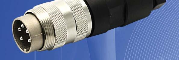


1 mphenol mphenol-tuchel Electronics GmbH C 09 //D Series Circular Connectors

2 Note from the CEO Ladies and Gentlemen, For over years mphenol has enjoyed success as the interconnection technology provider of choice to industry-leading companies around the world. One of our key strategic areas of focus has been and is the Industrial market. Our organization works with leading manufacturers across a wide range of applications - including Energy Generation & Distribution, Transportation, Heavy Equipment, Factory utomation, Wireless Outdoor, ChipCard Readers - enabling smarter, faster and better technologies to connect products to customer solutions. The Industrial market footprint of mphenol covers over facilities in more than different European countries and more than 0 countries worldwide. Our successful expansion into new regions as well as new industrial applications is a direct reflection of our agile, entrepreneurial management team and our unwavering commitment to execute mphenol s strategies for the benefit of our customers, shareholders and employees. Thank you for partnering with mphenol. Our entire organization is at your service. R. dam Norwitt President and CEO, mphenol Corporation

3 C 09 Make use of the best Use our global resources Think global, act local! Independently from where you are in Europe, we offer you our global expertise and great variety of products and technologies. nd in comfort with your personal contact. Our numerous European offices are your access to our global resources. OUR OFFICES IN EUROPE ND WORLDWIDE FRNCE CHIN USTRLI SOUTH FRIC GERMNY KORE MEXICO INDI UNITED KINGDOM TIWN US ITLY

4 C 09 SECURITY, RELIILITY ND COMFORTLE SERVICE FROM ONE SOURCE.
5 More time for important things: benefit from our service and diversity Enjoy security, reliability and comfortable service from one source. offers one of the most individual and most diversified service programmes in the market exclusively for industrial customers. ccess all possibilities of the mphenol group through your personal expert adviser. WIDE PRODUCT RNGE EXCLUSIVENESS ND FLEXIILITY Take advantage of a choice of mphenol products. Our broad product portfolio offers individual solutions from more than 90 member companies in the global mphenol group. One face to the customer: every inquiry is handled on an individual service level by your personal key account service partner. This ensures maximum transparency and best-in-class flexibility in the whole process. QULITY INDIVIDUL SOLUTIONS Interconnect systems need reliability, speed and flawless data transmission. We continuously test and guarantee the required standard in our products and also in our personal services. Your project requires an individual solution that is not available offthe-shelf? s your think tank and discussion partner we provide engineering support and solution-oriented development for your tailor-made mphenol product. SPEED ND VILILITY GLOL KEY CCOUNT SERVICE Smart and intelligent processes are the secret behind our service programme. Flexible planning and distribution, perfect logistics and highest availability are our key factors for best customer service. Our key account service is your individual entrance to global know-how, products and services. More than 90 mphenol companies around the world offer an extensive range of technologies and products. We offer access to our worldwide resources through one individual contact person.
6


7 C 09 Content Content C 09 Circular connectors with metal screw coupling and plastic back shell. Contacts: to, and, IP 0 when properly mated. Shieldable. Page C 09 Circular connectors with plastic bayonet coupling and plastic back shell. Contacts: to, and, IP 0 when properly mated. C 09 D Circular connectors with metal screw coupling and metal back shell. Contacts: to, and, IP 9K / IP / IP when properly mated. Shieldable. Connectors are compliant with ISG-standard 0 C 09 D+ Circular connectors with metal screw coupling and metal back shell. Contacts: to, and, IP 9K / IP when properly mated. Shieldable. Connectors are compliant with ISG-standard Crimp contacts Tools ccessories Protective Caps Current-Derating-Curves 9 Remarks / Safety classification 0 IP Code Summary of Part Numbers


8 C 09 C 09 M size Screw locking according to IEC 0--0 Metal locking ring Shieldable -, and positions for crimp and solder IP 0 Internal strain relief Male and female cable connectors straight and angled Male and female receptacles for front and rear panel mounting and PC mounting Coloured back shells optional UL registered under file number E 09 UL
9 C 09 Characteristics General Characteristics Standard Characteristics Number of contacts ) + Stereo View on termination side of male contact insert Contact arrangement DIN EN a 0-a Contact arrangement IEC 00-9 ) Electrical Characteristics Rated voltage ) IEC 0-00 V (00 V ) 0-a 00 V ( V ) 0-b 00 V ( V ) 0-a 00 V ( V ) 0-a 0-b 00 V ( V ) 0-a -a 0 V ( V ) Rated voltage UL 9 V 0 V Rated impulse withstand voltage ) IEC 0-00 V (0 V) 0 V (00 V) 00 V (0 V) Pollution degree ) IEC 0- () Installation category IEC 0- I Insulation group IEC 0- II, 00 CTI < 00 Current rating IEC 0-- UL 9 0 V (00 V) 0 / + 0 C / + 0 C / + 0 C / + 0 F please refer also to current derating curves page 9 Insulation resistance IEC 0-- > 0 0 Ω ) Contact resistance IEC 0-- < m Ω Climatic Characteristics Climatic category IEC 00-0 / 00 / Temperature range IEC C C / - 0 F... + F Mechanical Characteristics IP-degree IEC 09 IP 0 Insertion and withdrawal forces IEC 0-- N 90.oz 0 N 0.oz N.oz 0 N 0.oz N 0.oz Mechanical operation IEC 0-9- Silver 00 mating cycles Gold 000 mating cycles Materials Housing material brass or zinc die cast nickel plated or thermoplast Dielectric material thermoplastic Contact plating silver plated / gold plated ) Further Characteristics Termination technique solder, crimp Wire gauge Flammability Locking system IEC 00-9 DIN EN 0--0 solder: 0, mm / WG crimp: - pol (excluding S): 0,09 -,00 mm / - WG crimp: S,, S and -pol.: 0,09-0, mm / - WG UL 9 V0 metal screw coupling; tightening torque,0 Nm 0 N.oz 0 N 0.oz -a solder: 0, mm² / WG crimp: 0,09-0, mm² / WG Caution: Do not connect or disconnect under load. Metal housing parts shall be securely incorporated to protected ground. ) contact version: contact loading + ) Edition 00-0 ) Values in brackets are according to DIN EN 0--0 ) Under operating conditions >0 Ω ) Remark for gold plated contacts: In order to avoid brittle inter-metallic connections, gold-plated terminals have to be tin-plated in the solder area. M K J G H F E L C D M K J G H E F L O N C D IEC 0 ^= DIN VDE 00; IEC 0 -x ^= DIN EN 0 -x; IEC ^= DIN EN 0 0-9; IEC 0--0 ^= DIN EN
 crimp termination Straight (Please order crimp contacts separately, see page ) S ) ) S ) ) S ) ) S ) ) T 0 00")


 S ) ) T 0 00 T 00 T 00 00 T 0 00 T 00 T")
, (.) (.) (.0) PG 9 (.) (.0) PG, (.), (.) (.) (DI.0) for cable diameter -mm (DI.0) (DI.0) (DI.0) (DI.) (.) 0 ) See remark page 9 ) Contact arrangement acc.")
10 C 09 Male cable connector No. of Part Number solder termination Part Number Drawing Figure cont. silver plating gold plating ) crimp termination Straight (Please order crimp contacts separately, see page ) S ) ) S ) ) S ) ) S ) ) T 0 00 T 00 T T 0 00 T 0 00 T T 00 T 00 T 0 00 T 00 T 0 00 T 0 00 T 00 T T 0 00 T 0 0 T T 00 T 00 T 0 00 T 0 T 0 0 T 0 00 T 00 T T 0 00 T 00 T T 00 T 00 T 0 00 T 0 T 0 0 T 0 0 T 0 T 00 0 T 0 0 T 0 0 T 00 0 T 0 T 0 T 0 0 T 0 T 0 0 T 0 0 T 0 T 00 0 T 0 0 T 0 T 00 0 T 0 T 0 T 0 0 T 000 T T 0 0 T 0 T 00 0 T 0 0 T 0 T 00 0 T 0 T 0 T 0 0 T 00 T 0 00 T 0 0 T 0 T 00 0 T 0 0 T 0 T 00 0 T 0 T 0 T 0 0 T 00 T 0 00 T 0 0 T 0 T 00 0 T 0 0 T 0 T 00 0 T 0 T 0 T 0 0 T 0 T 0 0 T 0 T T 00 T 0 T T 00 T T T 0 T T 0 T 0 T T 00 T 0 T T 00 T T T 0 T T 0 T 0 T T 00 T 0 T T 00 T T T 0 T T 0 T 0 T T 00 T 0 T T 00 T T T 0 T T 0 for cable diameter -mm for cable diameter -mm for cable diameter -mm for cable diameter -mm Right-angled (Please order crimp contacts separately, see page ) S ) ) T 0 00 T 00 T T 0 00 T 00 T T 00 T 00 T 0 00 T 00 T 0 00 T 0 0 T 0 T 00 0 T 0 0 T 0 T 00 0 T 0 T 0 T 0 0 T 0 T 0 0 T 0 0 T 0 T 00 0 T 0 0 T 0 T 00 0 T 0 T 0 T 0 0 T 0 T 0 0, (.), (.) (.) (.0) PG 9 (.) (.0) PG, (.), (.) (.) (DI.0) for cable diameter -mm (DI.0) (DI.0) (DI.0) (DI.) (.) 0 ) See remark page 9 ) Contact arrangement acc. to DIN EN 0--0 "0X-b"
11 C 09 Male cable connector ssembly instruction ), cable diameter -mm tightening torque 0,Nm ), fold back shielding, tightening torque 0,Nm ssembly instruction ), cable diameter -mm or -mm tightening torque 0,Nm tightening torque Nm ), fold back shielding, tightening torque 0,Nm ssembly instruction ), right-angled, can be keyed to angle positions tightening torque 0,Nm ) fold back shielding,, ) For further information see page 0 ) Solder version only
 crimp termination Straight (Please order crimp contacts separately, see page ) S ) ) S ) ) S ) ) S ) ) T 00 T 00 T 0 00 T 00 T 00 T 0 00 T 00 T 00 T 0 00 T 00 T 00 T 00")

 S ) ) T 00 T 00 T 0 00 T 00 T 00 T 0 00 T 00 T 00 T 0 00 T 00 T 00 T 0 T 0 T 0 0 T 0 T 0 T 0 0 T 0 T 0 T 0 0 T 0 T 0 T 0 T 0 T 0 0 T 0 T 0 T 0 0 T 0 T 0 T")
12 C 09 Female cable connector No. of Part Number solder termination Part Number Drawing Figure cont. silver plating gold plating ) crimp termination Straight (Please order crimp contacts separately, see page ) S ) ) S ) ) S ) ) S ) ) T 00 T 00 T 0 00 T 00 T 00 T 0 00 T 00 T 00 T 0 00 T 00 T 00 T 00 T 00 T 0 00 T 00 T 0 T 0 00 T 00 T 00 T 0 00 T 0 T 0 T 00 T 00 T 0 00 T 00 T 00 T 0 00 T 00 T 00 T 0 00 T 0 T 0 T 0 T 0 T 0 0 T 0 T 0 T 0 0 T 0 T 0 T 0 0 T 0 T 0 T 0 T 0 T 0 0 T 0 T 0 T 0 0 T 0 T 0 T 0 0 T 000 T 000 T 0 T 0 T 0 0 T 0 T 0 T 0 0 T 0 T 0 T 0 0 T 00 T 00 T 0 T 0 T 0 0 T 0 T 0 T 0 0 T 0 T 0 T 0 0 T 00 T 00 T 0 T 0 T 0 0 T 0 T 0 T 0 0 T 0 T 0 T 0 0 T 0 T 0 T T T 0 T T T 0 T T T 0 T T T T T 0 T T T 0 T T T 0 T T T T T 0 T T T 0 T T T 0 T T T T T 0 T T T 0 T T T 0 T T for cable diameter -mm for cable diameter -mm for cable diameter -mm for cable diameter -mm Right-angled (Please order crimp contacts separately, see page ) S ) ) T 00 T 00 T 0 00 T 00 T 00 T 0 00 T 00 T 00 T 0 00 T 00 T 00 T 0 T 0 T 0 0 T 0 T 0 T 0 0 T 0 T 0 T 0 0 T 0 T 0 T 0 T 0 T 0 0 T 0 T 0 T 0 0 T 0 T 0 T 0 0 T 0 T 0 (.) (.) (.), (.0) PG 9 (.), (.0) PG (.) (.) (.) for cable diameter -mm (DI.0) (DI.0) (DI.0) (DI.0) (DI.) (.) ) See remark page 9 ) Contact arrangement acc. to DIN EN 0--0 "0X-b"
13 C 09 Female cable connector ssembly instruction ), cable diameter -mm tightening torque 0,Nm ), fold back shielding, tightening torque 0,Nm ssembly instruction ), cable diameter -mm or -mm tightening torque 0,Nm tightening torque Nm ), fold back shielding, tightening torque 0,Nm ssembly instruction ), right-angled, can be keyed to angle positions tightening torque 0,Nm ) fold back shielding,, ) For further information see page 0 ) Solder version only
 crimp termination Ring Nut (Hex nut on request) (Please order crimp contacts separately, see page ) S ) ) S ) ) T 000 T 000 T 0 000 T 000 T 00 T 0 000 T 000 T 000 T 0")
14 C 09 Male receptacle front mounting No. of Part Number solder termination Part Number Drawing Figure cont. silver plating gold plating ) crimp termination Ring Nut (Hex nut on request) (Please order crimp contacts separately, see page ) S ) ) S ) ) T 000 T 000 T T 000 T 00 T T 000 T 000 T T 00 T 00 T 00 T 0 00 T 00 T 00 T 0 00 T 00 T 00 T 0 00 T 00 T 00 ssembly instruction ) T 0 T 0 T 0 0 T 0 T 0 T 0 0 T 0 T 0 T 0 0 T 000 T 000 T 0 T 0 0 T 0 T 0 T 0 0 T 0 T 0 T 0 0 T 0 T 0 T 0 T 0 T 0 0 T 0 T 0 T 0 0 T 0 T 0 T 0 0 T 0 T 0 Mx0,, (.) (.0) termination: solder or crimp Mx0,, (.), (.), (.) 0, (.) (.00) (.00) (.0) pin length 0. mm from flange termination: straight dip solder Panel cutout max.,mm Tightening torque 0, Nm +0, (.09) 9, (.) +0, (DI.) (DI.) +0,, (.0) ) ) See remark page 9 Contact arrangement acc. to DIN EN 0--0 "0X-b" ) PC layout see page
 crimp termination Ring Nut (Hex nut on request) (Please order crimp contacts separately, see page ) S ) ) S ) ) S ) ) S ) ) T 00 T 00 T")
 T T T 0 T T T 0 T T T 0 T 00 T 00 T 0 T 0 0 T 0 T 0 T 0 0 T 0 T 0 T 0 0 T 0 T 0 T 0 T 0 T 0 0 T 0 T 0 T 0 0 T 0 T 0 T 0 0 T 0 T 0, (.) (DI.) (.00), (.")

15 C 09 Male receptacle rear mounting No. of Part Number solder termination Part Number Drawing Figure cont. silver plating gold plating ) crimp termination Ring Nut (Hex nut on request) (Please order crimp contacts separately, see page ) S ) ) S ) ) S ) ) S ) ) T 00 T 00 T 0 00 T 00 T 00 T 0 00 T 00 T 00 T 0 00 T 0 T 0 T 00 T 0 00 T 00 T 00 T 0 00 T 00 T 00 T 0 00 T 00 T 00 T T 0 T T T 0 T T T 0 T 0 T 0 0 T 0 T 0 T 0 0 T 0 T 0 T 0 0 ssembly instruction ) T T T 0 T T T 0 T T T 0 T 00 T 00 T 0 T 0 0 T 0 T 0 T 0 0 T 0 T 0 T 0 0 T 0 T 0 T 0 T 0 T 0 0 T 0 T 0 T 0 0 T 0 T 0 T 0 0 T 0 T 0, (.) (DI.) (.00), (.) (.0) termination: solder or crimp Mx0, pin length 0. mm from flange termination: straight dip solder pin length. mm from flange termination: straight dip solder pin length 9. mm from flange termination: straight dip solder Panel cutout max.,mm +0, (.09) Tightening torque 0, Nm +0, 9, (.) +0,, (.0) ) See remark page 9 ) Contact arrangement acc. to DIN EN 0--0 "0X-b" ) PC layout see page
16 ,,0 C 09 Male Receptacles PC-Layout to IEC Pol. Pol. Pol. Stereo Pol. Pol. Pol., Pol. DIN Pol. Stereo Pol. Pol., DIN Stereo DIN,0 DIN Pol. DIN DIN Pol. DIN,9,0 PC-Layout (components,0 side of DIN circuit board),0 DIN,9,9,0,0 Male Receptacles front mounting Pol. rear mounting straight Pol. Stereo POL POL, POL DIN POL S ),0,0,9,,0,,0,0, 0,,,,,,,9,0,0, 0, 0,,,,,,,,,, 0 G G H H J M J MK F E K F E L D L D C C,,,,0,,,,9,,0,,,9,9 Pol. Pol. Pol. Pol. Pol. Pol., Pol. Pol. Pol. Pol. Pol.,0,0 DIN DIN DIN 9 Pol. DIN DIN 9 DIN 9 DIN DIN,9 POL,0,0 POL,0,0 POL ),9,9,9 POL,9,9 Pol. DIN 9,9,,0,0,,,0,0,0,0 Pol. POL POL Pol. Pol. Pol. Pol. Pol. Pol. 9,0 Pol.,0 DIN DIN 9,0 9,0 9,0,0,9,9,0,0,0,9 0, K J,0 H M,0 L G 9,0 C F, 0, D E,,0 Fig. C 09-a,0,0,,,9 0, 0, K J,0 H,0, N M L G 9,0 C O F 0, D E 0,,0,0, 0,,0,0,0,,0,0 0,0, 0 G G H H J F J F M M K E K EN O N O L D L D C C,,0, 0,,,0,,,0 0,,,,0,, 0,,,,0,,,,,0 0,9,,9 Pol., 0 K,9 J,0 H,, M,0 L G 9,0 C F,0 0, D E G H J F M K E N O L D 9,0,,0 C 0,,0,0,0,,0,,,,,,,,, 0,,,0,,,0 0,, P P DIN P P DIN,9 ) Contact arrangement acc. to DIN EN 0--0 "0X-b"
17 C 09 Your Notes
 crimp termination Ring Nut (Hex nut on request) (Please order crimp contacts separately,")

, (.) (.")
 pin length 9 mm from flange termination: straight dip solder (.")
, (.) (.00) (.) Mx0, (.) Mx0, (.), (.) (.), (.) (DI.) (.00) (DI.")
18 C 09 Female receptacle front mounting No. of Part Number solder termination Part Number Drawing Figure cont. silver plating gold plating ) crimp termination Ring Nut (Hex nut on request) (Please order crimp contacts separately, see page ) S ) ) S ) ) S ) ) S ) ) T 000 T 000 T T 000 T 00 T T 000 T 000 T T 000 T 000 T 00 T 00 T 0 00 T 00 T 9 00 T 0 00 T 00 T 00 T 0 00 T 00 T 00 T T 0 T T 9 T 0 T T T 0 T 0 T 0 0 T 0 T 9 0 T 0 0 T 0 T 0 T 0 0 ssembly instruction ) T 0 T 0 T 0 0 T 0 T 9 0 T 0 0 T 0 T 0 T 0 0 T 00 T 00 T 0 T 0 T 0 0 T 0 T 9 0 T 0 0 T 0 T 0 T 0 0 T 0 T 0 T 0 T 0 T 0 0 T 0 T 9 0 T 0 0 T 0 T 0 T 0 0 T 0 T 0 Mx0, Mx0, (.), (.) (.00) pin length mm from flange termination: straight dip solder 9 (.) pin length 9 mm from flange termination: straight dip solder (.9) pin length mm from flange termination: straight dip solder Panel cutout (.00) (DI.) (.0) *Measure - and -pol.=±0, Ma bei - und -pol.= termination: solder or crimp (.), (.) (.00) (.) Mx0, (.) Mx0, (.), (.) (.), (.) (DI.) (.00) (DI.) (.00) (DI.) max.mm Tightening torque 0, Nm +0, (.09) 9, (.) +0, +0,, (.0) ) See remark page 9 ) Contact arrangement acc. to DIN EN 0--0 "0X-b" ) PC layout see page
 crimp termination Ring Nut (Hex nut on request) (Please order crimp contacts separately, see page ) S ) ) S ) ) S ) ) S ) )")
 T T T 0 T T 9 T 0 T T T 0 T T T 0 T 0 T 0 0 T 0 T 9 0 T 0 0 T 0 T 0 T 0 0 T 0 T 0 T")
 pin length 0. mm from flange termination: straight dip solder (.) (DI.) pin length. mm from flange termination: straight dip solder (.) (DI.) (.) 0, (.")
 max.,mm +0, (.09) Tightening torque 0, Nm +0, 9, (.) +0,, (.")
19 C 09 Female receptacle rear mounting No. of Part Number solder termination Part Number Drawing Figure cont. silver plating gold plating ) crimp termination Ring Nut (Hex nut on request) (Please order crimp contacts separately, see page ) S ) ) S ) ) S ) ) S ) ) T 00 T 00 T 0 00 T 00 T 9 00 T 0 00 T 00 T 00 T 0 00 T 00 T 00 T 00 T 00 T 0 00 T 00 T 9 00 T 0 00 T 00 T 00 T 0 00 T 00 T 00 T T 0 T T 9 T 0 T T T 0 T T T 0 T 0 0 T 0 T 9 0 T 0 0 T 0 T 0 T 0 0 T 0 T 0 ssembly instruction ) T T T 0 T T 9 T 0 T T T 0 T T T 0 T 0 T 0 0 T 0 T 9 0 T 0 0 T 0 T 0 T 0 0 T 0 T 0 T T 0 T T 9 T 0 T T T 0 T T T T 0 T T 9 T 0 T T T 0 T T T 0 T 0 T 0 0 T 0 T 9 0 T 0 0 T 0 T 0 T 0 0 T 0 T 0 (DI.) *Measure Ma - bei and - und -pol.=0±0, termination: solder or crimp (DI.) pin length 0. mm from flange termination: straight dip solder (.) (DI.) pin length. mm from flange termination: straight dip solder (.) (DI.) (.) 0, (.), (.0) 9, (.), (.), (.), (.), (.) (.00) (.00) Mx0,, (.) Mx0, (.00), (.) Mx0, (.00), (.) Mx0, pin length 9. mm from flange termination: straight dip solder Panel cutout, (.) max.,mm +0, (.09) Tightening torque 0, Nm +0, 9, (.) +0,, (.0) ) ) See remark page 9 Contact arrangement acc. to DIN EN 0--0 "0X-b" ) PC layout see page 9
 crimp termination Right-angled Ring Nut (Hex nut on request) (Please order crimp contacts separately, see page ), (.),, (.) (.00) T 90 S ) ) T 0 90 (.0) (.) Mx0, (.")
 crimp termination Right-angled Ring Nut (Hex nut on request) (Please order crimp contacts separately, see page ) Fig. C 09-9a, T 900 (.9), (.) (.00) S ) T 9 900 ) T 900 T 0 900 T 0 9 (.")
20 C 09 Female receptacle 90 rear mounting No. of Part Number solder termination Part Number Drawing Figure cont. silver plating gold plating ) crimp termination Right-angled Ring Nut (Hex nut on request) (Please order crimp contacts separately, see page ), (.),, (.) (.00) T 90 S ) ) T 0 90 (.0) (.) Mx0, (.00) (DI.) C 09 Female receptacle 90 PC mounting No. of Part Number solder termination Part Number Drawing Figure cont. silver plating gold plating ) crimp termination Right-angled Ring Nut (Hex nut on request) (Please order crimp contacts separately, see page ) Fig. C 09-9a, T 900 (.9), (.) (.00) S ) T ) T 900 T T 0 9 (.9), (.), (.), (.) Mx0, (DI.) Panel cutout ) Female receptacle 90 rear mounting PC mounting +0, (.09) 9, (.) +0, +0,, (.0) ) See remark page 9 ) Contact arrangement acc. to DIN EN 0--0 "0X-b" ) PC layout see page

")
 ) See remark page 9 Contact arrangement acc.")
21 C 09 Female receptacle 90 PC flange mounting No. of Part Number solder termination Part Number Drawing Figure cont. silver plating gold plating ) crimp termination Right-angled (Please order crimp contacts separately, see page ) T S ) T 0 ) Panel cutout ) Female receptacle 90 PC flange mounting ) ) See remark page 9 Contact arrangement acc. to DIN EN 0--0 "0X-b" ) PC layout see page
22 O O O O C 09 Female receptacle PC-Layout contact arrangement acc. to IEC Fig. C 09-a Fig. C 09-a Pol. Pol. Pol. Stereo Pol. Pol. Pol. Stereo Pol. Pol. PC-Layout, DIN (components side of circuit board) DIN, contact arrangement DIN acc. to DIN DIN contact arrangement,0 acc. IEC 0 to 0-9 IEC 0 0-9,9 DIN,0,9,0 Pol. Pol. Female receptacle front mounting Pol. Pol. rear mounting Pol. Pol. Pol. Stereo DIN POL POL,, DIN POL DIN DIN POL S,0,0 ),0,0,0,9,,,0,0,9, 0,,,,, Female receptacle 90 PC mounting (.9) (.9) POL POL S ) Fig. C 09-a Pol. Pol. Stereo POL ) 0 Pol. Fig. C 09-a 0 Pol. POL,, Female receptacle (.9) 90 PC flange mounting (.9) (.0), Pol. Pol. Pol. (.0), Pol. (.0) (.0) POL ±0, ±0, (x), ±0,POL +0, (x), +0, ±0, (x),, 0, 0,,,,0,0,0,,,,0,,9,9,,,,0 Pol. Pol. Pol. Pol. Pol. Pol. Pol. Pol. DIN DIN POL POL DIN DIN 9 POL ) 9 DIN POL DIN,0,0,0,0,9,9,9,9 Stereo Pol. Stereo Pol. Pol. Pol. Pol. Pol. DIN DIN,9 DIN,0,0 DIN 9,9,0,0,9,,0,0,,0,0 9,0 POL 9,0 POL,0,0,0,,0 Pol. Pol. Pol.,,0 Pol. Pol. 9,0 Pol. DIN G 9,0 DIN G H,0 H,9 J F,9,0 M J M K E K F E N O Pol. Pol. Pol. L D L D 9 Pol. DIN Pol. Pol. Pol.,9,9 C G DIN 9 C DIN H G J,9,9 M H K F E J F M 0, K E N O 0, L D L D,0, C C,0 Female receptacle,0 90 rear mounting 0,,0 Fig. C 09-a Fig. C 09-a 0, Pol.,0 POL Pol. POL, 0, +0, (x) 0, +0, (x) 0,,0,0 +0, (x) 0, +0, (x) (.0) (.0) (.0) (.0) fÿr,0 Lochbild fÿr Leiterplatte,0,0, Pol.,0 0,,9,9 Pol. 0 K ±0,0 J,0,9 H,,0, (.) Lochbild fÿr Leiterplatte Lochbild fÿr Leiterplatte N M L G 9,0 C F 0, D K,, (.09) (.09) E J,0, (.09), (.09) ±0,0 (.) H,,0, N M L G 9,0 C F 0,,0 D E,,0,,,,, 0,,,,,,0 0,,, (.) (.) (DI.) ±0, (.0), (.0), (.0) (.9) (.9) 0 (.9) 0 ±0,0 (.) (.9) (.9) (.9) (.9) ±0,0 ±0,,0 (x) 0, (.) (.9), (.) ±0, (.0) ±0,0 (x) ±0,0 (x) (.) (.) Pol. (.9) (.9) Pol. Pol.,, (.09) (.09) 0, (.9) 0, 0, (.9) (.9) (.9) (.9) (x) (DI.0), ±0,0 ±0,0 (.) (.),,9,, 0,,9, (DI.) (.) ±0,0 (x) (.) ±0,, (.) ±0, (.0) (x) (DI.0) K J,0, (.09), (.09) H M,0 L G 9,0,, (.09) (.09) C F, 0 0, D ±0, (.0) E (.9) (.9) (.9) (x), (DI.0) (.9), ±0,0 ±0,0 (.) (.),,0 Fig. C 09-a,,0,0,,,,,9,0,,9,, 0, (.9) Fig. C 09-0aFig. C 09-0a (.9) 0 Pol. (.9) 0 Pol. +0,, +0,, +0, +0, +0,, ±0,0 ±0,0 (.) (.) ±0,0, (.0), (.0),, (.09) (.09) (.), (.)(DI.) ±0,0 (x) (.) 0 (.9) 0 (.9) ±0,, (.) (x), (DI.) ±0,0, (.09) 0, 0, (.9) (.9), (.09) ±0, (.9) (.9) (x) 0, (.) 0, (.9) (.9), (.) (x), (DI.0), ±0,0 (.) +0,, 0, 0, ±0,0 (.), (.09), (.09),,0 ±0,0 (x) ±0,0 (x) (.) (.) Pol. Stereo (.9) (.9),0 0 K J,,0 H 0 M,0, L G 9,0 C F, (.09), (.09) K J,0 0, D H E M,0 K L J,0 G 9,0 C F H,, (.0) (.0),0, N 0, M D L G,0 9,0, (.9) (.9), (.0) (.0), (.09), (.09) E (.9) (.9) (.9) (.9) C,,,0 F 0, D E,0,,0 (.9) (.9),0 Pol. Pol.,, 0, (.9) 0, (.9), (.09), (.09) (.9) (.9) 0, (.9) 0, (.9),0,,0,0, 0 (.09), (.09),, (.09), (.09), (.09), (.09),9,, (.0) (.0) K J,0, H,0, N M 9,0 L G 0 0 (.9) (.9) C 0 0 (.9), (.9), (.0) (.0),,0, F 0, D (.9) (.9) (.9) (.9) (.9) (.9) E, (.09), (.09) 0, (.9) 0, (.9), (.09), (.09) 0, (.9) 0, (.9),,, 0,, (.9) (.9) (.9) (.9),,,,0 Pol. Pol. Stereo Pol. Pol.,, 0,,0 P DIN, P DIN, P P,9 0 0 Fig. Fig. C C 09-a ) Contact arrangement acc. to DIN EN 0--0 "0X-b"
23 C 09 Your Notes


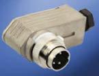
24 C 09 C 09 ayonet locking Plastic locking ring -, and positions for crimp and solder IP 0 Internal strain relief Male and female cable connectors straight and angled Male and female receptacles for front and rear panel mounting and PC mounting Coloured back shells optional UL registered under file number E 09 UL
25 C 09 Characteristics General Characteristics Standard Characteristics Number of contacts + Stereo View on termination side of male contact insert Contact arrangement DIN EN a 0-a Contact arrangement IEC 00-9 ) Electrical Characteristics Rated voltage IEC 0-00 V (00 V ) 0-a 00 V ( V ) 0-b 00 V ( V ) 0-a 00 V ( V ) 0-a 0-b 00 V ( V ) 0-a -a 0 V ( V ) Rated voltage UL 9 V 0 V Rated impulse withstand voltage IEC 0-00 V (0 V) 0 V (00 V) 00 V (0 V) Pollution degree IEC 0- () Installation category IEC 0- I Insulation group IEC 0- II, 00 CTI < 00 Current rating IEC 0-- UL 9 0 V (00 V) 0 / + 0 C / + 0 C / + 0 C / + 0 F please refer also to current derating curves page 9 Insulation resistance IEC 0-- > 0 0 Ω ) Contact resistance IEC 0-- < m Ω Climatic Characteristics Climatic category IEC 0-0 / 00 / Temperature range IEC C C / - 0 F... + F Mechanical Characteristics IP-degree IEC 09 IP 0 Insertion and withdrawal forces IEC 0-- N 90.oz 0 N 0.oz N.oz 0 N 0.oz N 0.oz Mechanical operation IEC 0-9- Silver 00 mating cycles Gold 000 mating cycles Materials Housing material brass or zinc die cast nickel plated or thermoplast Dielectric material thermoplastic Contact plating silver plated / gold plated ) Further Characteristics Termination technique solder, crimp Wire gauge Flammability Locking system solder: 0, mm / WG crimp: - pol (excluding S): 0,09 -,00 mm / - WG crimp: S,, S and -pol.: 0,09-0, mm / - WG UL 9 V0 bayonet 0 N.oz E F L C D M K J G H 0 N 0.oz E F L N O C D -a solder: 0, mm² / WG crimp: 0,09-0, mm² / WG Caution: Do not connect or disconnect under load. Metal housing parts shall be securely incorporated to protected ground. ) Edition 00-0 ) Under operating conditions >0 Ω ) Remark for gold plated contacts: In order to avoid brittle inter-metallic connections, gold-plated terminals have to be tin-plated in the solder area. M K J G H IEC 0 ^= DIN VDE 00; IEC 0 -x ^= DIN EN 0 -x; IEC ^= DIN EN 0 0-9; IEC 0--0 ^= DIN EN 0--0
 crimp termination Locking inside straight (Please order crimp contacts separately, see page ) S ) ) S ) ) S ) ) T 0 T 0 T 0 T 9 0 T 0 T 0 T 0 T 0 T 0 T 0 T 0 T 0 T 0 T 9")
26 C 09 Male cable connector bayonet locking inside (mateable with locking outside) No. of Part Number solder termination Part Number Drawing Figure cont. silver plating gold plating ) crimp termination Locking inside straight (Please order crimp contacts separately, see page ) S ) ) S ) ) S ) ) T 0 T 0 T 0 T 9 0 T 0 T 0 T 0 T 0 T 0 T 0 T 0 T 0 T 0 T 9 0 T 0 T 0 T 0 T 0 T 0 T 0 T 0 T 0 T 0 T 9 0 T 0 T 0 T 0 T 0 T 0 T 0 T T T T 9 T T T T T T T T T T 9 T T T T T T T T T T 9 T T T T T T T T T T 9 T T T T T T T T T T 9 T T T T T T T T T T 9 T T T T T T for cable diameter -mm (.) (.0) for cable diameter -mm for cable diameter -mm Locking inside straight full plastic (Please order crimp contacts separately, see page ) S ) ) T 99 T 99 T 99 T 9 99 T 99 T 99 T 99 T 99 T 99 T 9 99 T 99 T 99 T 9 T 9 T 9 T 9 T 9 T 9 T 9 for cable diameter -mm Locking inside right-angled (Please order crimp contacts separately, see page ) S ) ) T 00 T 00 T 00 T 9 00 T 00 T 00 T 00 T 00 T 00 T 00 T 0 T 0 T 0 T 9 0 T 0 T 0 T 0 T 0 T 0 T 0 T 0 T 0 T 0 T 9 0 T 0 T 0 T 0 T 0 T 0 T 0, (.), (.) PG 9 (.) (.0) PG ca. (.) 0 (.99), (.9) for cable diameter -mm (DI.) (DI.) (DI.) (DI.) (DI.) (.) ) See remark page ) Contact arrangement acc. to DIN EN 0--0 "0X-b"
27 C 09 Male cable connector bayonet locking inside (mateable with locking outside) ssembly instruction ), cable diameter -mm tightening torque 0,Nm ), fold back shielding, tightening torque 0,Nm ssembly instruction ), cable diameter -mm or -mm tightening torque Nm tightening torque 0,Nm ), fold back shielding, tightening torque 0,Nm ssembly instruction ), right-angled, can be keyed to angle positions tightening torque 0,Nm ) fold back shielding,, ) For further information see page 0 ) Solder version only
 crimp termination Locking outside straight (Please order crimp contacts separately, see page ) S ) ) S ) ) S ) ) T 9 0 T 9 0 T 9 0 T 99 0 T 9 0 T 9 0 T 9 0 T 9 0 T 9 0 T")
, (.")
28 C 09 Male cable connector bayonet locking outside (mateable with locking inside) No. of Part Number solder termination Part Number Drawing Figure cont. silver plating gold plating ) crimp termination Locking outside straight (Please order crimp contacts separately, see page ) S ) ) S ) ) S ) ) T 9 0 T 9 0 T 9 0 T 99 0 T 9 0 T 9 0 T 9 0 T 9 0 T 9 0 T 9 0 T 9 0 T 9 0 T 9 0 T 99 0 T 9 0 T 9 0 T 9 0 T 9 0 T 9 0 T 9 0 T 9 0 T 9 0 T 9 0 T 99 0 T 9 0 T 9 0 T 9 0 T 9 0 T 9 0 T 9 0 T 9 T 9 T 9 T 99 T 9 T 9 T 9 T 9 T 9 T 9 T 9 T 9 T 9 T 99 T 9 T 9 T 9 T 9 T 9 T 9 T 9 T 9 T 9 T 99 T 9 T 9 T 9 T 9 T 9 T 9 T 9 T 9 T 9 T 99 T 9 T 9 T 9 T 9 T 9 T 9 T 9 T 9 T 9 T 99 T 9 T 9 T 9 T 9 T 9 T 9 T 9 T 9 T 9 T 99 T 9 T 9 T 9 T 9 T 9 T 9, (.), (.) for cable diameter -mm (.) (.0) PG 9 for cable diameter -mm (.) (.0) PG for cable diameter -mm (DI.) (DI.) (DI.) ) See remark page ) Contact arrangement acc. to DIN EN 0--0 "0X-b"
29 C 09 Male cable connector bayonet locking outside (mateable with locking inside) ssembly instruction ), cable diameter -mm tightening torque 0,Nm ), fold back shielding, tightening torque 0,Nm ssembly instruction ), cable diameter -mm or -mm tightening torque Nm tightening torque 0,Nm ), fold back shielding, tightening torque 0,Nm ) For further information see page 0 ) Solder version only 9
 crimp termination Locking inside straight (Please order crimp contacts separately, see page ) S ) ) S ) ) S ) ) T 0 T 0 T 0 T 9 0 T 0 T 0 T 0 T 0 T 0 T 0 T 0 T 0 T 0 T")
, (.")
 S ) ) T 00 T 00 T 00 T 9 00 T 00 T 00 T 00 T 00 T 00 T 00 T 0 T 0 T 0 T 9 0 T 0 T 0 T 0 T 0 T 0 T")
30 C 09 Female cable connector bayonet locking inside (mateable with locking outside) No. of Part Number solder termination Part Number Drawing Figure cont. silver plating gold plating ) crimp termination Locking inside straight (Please order crimp contacts separately, see page ) S ) ) S ) ) S ) ) T 0 T 0 T 0 T 9 0 T 0 T 0 T 0 T 0 T 0 T 0 T 0 T 0 T 0 T 9 0 T 0 T 0 T 0 T 0 T 0 T 0 T 0 T 0 T 0 T 9 0 T 0 T 0 T 0 T 0 T 0 T 0 T T T T 9 T T T T T T T T T T 9 T T T T T T T T T T 9 T T T T T T T T T T 9 T T T T T T T T T T 9 T T T T T T T T T T 9 T T T T T T for cable diameter -mm (.), (.0) for cable diameter -mm for cable diameter -mm Locking inside straight full plastic (Please order crimp contacts separately, see page ) S ) ) T 99 T 99 T 99 T 99 T 99 T 9 T 9 T 9 T 9 T 9 for cable diameter -mm Locking inside right-angled (Please order crimp contacts separately, see page ) S ) ) T 00 T 00 T 00 T 9 00 T 00 T 00 T 00 T 00 T 00 T 00 T 0 T 0 T 0 T 9 0 T 0 T 0 T 0 T 0 T 0 T 0 T 0 T 0 T 0 T 9 0 T 0 T 0 T 0 T 0 T 0 (.) (.) PG 9 (.), (.0) PG ca. (.), (.9) for cable diameter -mm (.) (DI.) (DI.) (DI.) (DI.) (DI.), (.9) 0 ) See remark page ) Contact arrangement acc. to DIN EN 0--0 "0X-b"
31 C 09 Female cable connector bayonet locking inside (mateable with locking outside) ssembly instruction ), cable diameter -mm tightening torque 0,Nm ), fold back shielding, tightening torque 0,Nm ssembly instruction ), cable diameter -mm or -mm tightening torque Nm tightening torque 0,Nm ), fold back shielding, tightening torque 0,Nm ssembly instruction ), right-angled, can be keyed to angle positions tightening torque 0,Nm ) fold back shielding,, ) For further information see page 0 ) Solder version only
 crimp termination Locking outside straight (Please order crimp contacts separately, see page ) S ) ) S ) ) S ) ) T 0 T 0 T 0")

 (.) (.) (.) PG 9 (.) (.) PG ca. 9 (.) for cable diameter -mm, (.) (DI.) (DI.) (DI.) (DI.) ) See remark page ) Contact arrangement acc.")
32 C 09 Female cable connector bayonet locking outside (mateable with locking inside) No. of Part Number solder termination Part Number Drawing Figure cont. silver plating gold plating ) crimp termination Locking outside straight (Please order crimp contacts separately, see page ) S ) ) S ) ) S ) ) T 0 T 0 T 0 T 9 0 T 0 T 0 T 0 T 0 T 0 T 0 T 0 T 0 T 0 T 9 0 T 0 T 0 T 0 T 0 T 0 T 0 T 0 T 0 T 0 T 9 0 T 0 T 0 T 0 T 0 T 0 T 0 T T T T 9 T T T T T T T T T T 9 T T T T T T T T T T 9 T T T T T T T T T T 9 T T T T T T T T T T 9 T T T T T T T T T T 9 T T T T T T for cable diameter -mm for cable diameter -mm for cable diameter -mm Locking outside straight full plastic (Please order crimp contacts separately, see page ) S ) ) T 99 T 99 T 99 T 99 T 99 T 9 T 9 T 9 T 9 T 9 (.) (.) (.) (.) PG 9 (.) (.) PG ca. 9 (.) for cable diameter -mm, (.) (DI.) (DI.) (DI.) (DI.) ) See remark page ) Contact arrangement acc. to DIN EN 0--0 "0X-b"
33 C 09 Female cable connector bayonet locking outside (mateable with locking inside) ssembly instruction ), cable diameter -mm tightening torque 0,Nm, fold back shielding, tightening torque 0,Nm ssembly instruction ), cable diameter -mm or -mm tightening torque Nm tightening torque 0,Nm, fold back shielding, tightening torque 0,Nm ) For further information see page 0 ) Solder version only
 crimp termination Locking outside Snap in (Please order crimp contacts separately, see page ) S ) ) T 00 T 00 T 00 T 9 00 T 00 T 00 T 00 T 00 T 00 T 00 Panel cutout T T")
34 C 09 Male receptacle bayonet locking outside (mateable with locking inside) front mounting full plastic No. of Part Number solder termination Part Number Drawing Figure cont. silver plating gold plating ) crimp termination Locking outside Snap in (Please order crimp contacts separately, see page ) S ) ) T 00 T 00 T 00 T 9 00 T 00 T 00 T 00 T 00 T 00 T 00 Panel cutout T T T T 9 T T T T T T T 0 T 0 T 0 T 9 0 T 0 T 0 T 0 T 0, (.9) (.90) max. WandstŠrke panel thickness max., +0, +0, (DI.), +0, (.0), (.) +0, +0,, (.) ) See remark page ) Contact arrangement acc. to DIN EN 0--0 "0X-b"

 S ) ) S ) ) T 00 T 00 T 00 T 9 00 T 00 T")
 (.00), (.9), (.9), (.9) max. WandstŠrke panel thickness max.")
35 C 09 Female receptacle bayonet locking outside (mateable with locking inside) front mounting full plastic No. of Part Number solder termination Part Number Drawing Figure cont. silver plating gold plating ) crimp termination Locking outside Ring Nut (Hex nut on request) (Please order crimp contacts separately, see page ) S ) ) T 000 T 000 T 000 T 000 T 000 T 0 T 0 T 0 T 0 T 0 T 00 T 00 T 00 T 00 T 00 Locking outside Snap in (Please order crimp contacts separately, see page ) S ) ) S ) ) T 00 T 00 T 00 T 9 00 T 00 T 00 T 00 T 00 T 00 T 00 T 00 T 00 T 00 T 9 00 T 00 T 00 T 00 T 00 T 00 T 00 Panel cutout T T T T 9 T T T T T T T T T T 9 T T T T T T T 0 T 0 T 0 T 9 0 T 0 T 0 T 0 T 0 T 0 T 0 T 9 0 T 0 T 0 T 0 T 0 Mx0, 9, (.) (.00), (.9), (.9), (.9) max. WandstŠrke panel thickness max., +0, (DI.) (DI.) (.90) max. WandstŠrke panel thickness max., +0, +0, Locking inside Snap in (Please order crimp contacts separately, see page ) 9 (.) +0, (DI.), +0, (.0), (.) +0, +0,, (.) ) See remark page ) Contact arrangement acc. to DIN EN 0--0 "0X-b"
 crimp termination Locking outside Ring Nut (Hex nut on request) (Please order crimp contacts separately, see page ) S ) ) T 00 T 00 T 00 T 9 00 T 00 T 00 T 00 T 00 T 00")
36 C 09 Female receptacle bayonet locking outside (mateable with locking inside) rear mounting metal No. of Part Number solder termination Part Number Drawing Figure cont. silver plating gold plating ) crimp termination Locking outside Ring Nut (Hex nut on request) (Please order crimp contacts separately, see page ) S ) ) T 00 T 00 T 00 T 9 00 T 00 T 00 T 00 T 00 T 00 T 00 T T T T 9 T T T T T T T 0 T 0 T 0 T 9 0 T 0 T 0 T 0 T 0, (.) (DI.), (.) (.) (.00) Mx0, Panel cutout Montageausschnitt siehe Seite +0, (.09) 9, (.) +0, +0,, (.0) ) See remark page ) Contact arrangement acc. to DIN EN 0--0 "0X-b"
 90 PC mounting No.")
 crimp termination Locking outside (Please")
 T 900 T 9 900 T 900 T 900 Position when mounted directly next to another")
37 C 09 Female receptacle bayonet locking outside (mateable with locking inside) 90 PC mounting No. of Part Number solder termination Part Number Drawing Figure cont. silver plating gold plating ) crimp termination Locking outside (Please order crimp contacts separately, see page ) T 00 T 00 S ) T 9 00 T 00 ) S ) ) T 900 T T 900 T 900 Position when mounted directly next to another ) See remark page ) Contact arrangement acc. to DIN EN 0--0 "0X-b"
38 C 09 Female receptacle PC-Layout 0 (.9), (.09) PC-Layout (components side of circuit board) Female receptacle bayonet locking outside (mateable with locking inside) 90 PC mounting tte POL POL Pol POL Stereo Pol. Stere POL, (.0), (.09) (.9) (.9), (.09) (.9), (.9), (.0), (.09) POL POL Pol. Stereo Pol. Stereo Pol. Pol. 0 (.9) (.9), (.09) (.9) 0 0,, (.9) (.9) (.0) (.0), (.09) (.9), (.09) (.9), (.09) 0 (.9) (.9) (.9), (.09), (.09) (.9), (.9) Fig. C 09-a Fig. C 09-a 0 0 Pol. Pol.,, (.9) (.9) (.0) (.0), (.09), (.09) (.9), (.09) (.9) 0, (.9) (.0), (.09) (.9) (.9), (.09), (.09) (.9), (.9),, (.09) 0, (.9) (.0), (.09) (.9) (.9), (.09), (.09) (.9), (.9) (.09) ) ), (.09) (.9) (.9), (.09), (.9), (.09), (.9), (.09) (.9) (.9), (.09) (.9) (.9), (.09), (.9), (.9), (.09), (.09) (.9) (.9), (.09) (.9) (.9), (.09), (.9), (.9)
39 C 09 Your Notes 9


40 C 09 C 09 D M size Screw locking according to IEC 0--0 Metal locking ring Shieldable -, and positions for crimp and solder IP 9 K / IP / IP Internal strain relief Male and female cable connectors straight and angled Male and female receptacles for front and rear panel mounting and PC mounting UL registered under file number E 09 UL Connectors are compliant with ISG-standard 0
41 C 09 D Characteristics General Characteristics Standard Characteristics Number of contacts + Stereo View on termination side of male contact insert Contact arrangement DIN EN a 0-a Contact arrangement IEC 00-9 ) Electrical Characteristics Rated voltage ) IEC 0-00 V (00 V ) 0-a 00 V ( V ) 0-b 00 V ( V ) 0-a 00 V ( V ) 0-a 0-b 00 V ( V ) 0-a -a 0 V ( V ) Rated voltage UL 9 V 0 V Rated impulse withstand voltage ) IEC 0-00 V (0 V) 0 V (00 V) 00 V (0 V) Pollution degree ) IEC 0- ( ) ) Installation category IEC 0- I Insulation group IEC 0- II, 00 CTI < 00 Current rating IEC 0-- UL 9 0 V (00 V) 0 / + 0 C / + 0 C / + 0 C / + 0 F please refer also to current derating curves page 9 Insulation resistance IEC 0-- > 0 0 Ω ) Contact resistance IEC 0-- < m Ω Climatic Characteristics Climatic category IEC 0-0 / 00 / Temperature range IEC C C / - 0 F... + F Salt Spray Resistance DIN IEC 00- -, Test Ka h Mechanical Characteristics IP-degree IEC 09 IP 9K / IP / IP (in mated condition) Insertion and withdrawal forces IEC 0-- N 90.oz 0 N 0.oz N.oz 0 N 0.oz N 0.oz Mechanical operation IEC 0-9- Silver 00 mating cycles Gold 000 mating cycles Materials Housing material brass or zinc die cast nickel plated or thermoplast Dielectric material thermoplastic Contact plating silver plated / gold plated ) Further Characteristics Termination technique solder, crimp Wire gauge solder: 0, mm / WG crimp: - pol (excluding S): 0,09 -,00 mm / - WG crimp: S,, S and -pol.: 0,09-0, mm / - WG 0 N.oz Flammability UL 9 V0 Locking system IEC 00-9 DIN EN metal screw coupling; tightening torque,0 -, Nm 0--0 UL UL 9 Conditions of acceptability 0 N 0.oz L O C D -a solder: 0, mm² / WG crimp: 0,09-0, mm² / WG Caution: Do not connect or disconnect under load. Metal housing parts shall be securely incorporated to protected ground. ) Edition 00-0 ) Values in brackets are according to DIN EN 0--0 ) Designed acc. pollution degree ; can be used under pollution degree when the rules of IEC 0- are fulfilled ) Under operating conditions >0 Ω ) Remark for gold plated contacts: In order to avoid brittle inter-metallic connections, gold-plated terminals have to be tin-plated in the solder area. IEC 0 ^= DIN VDE 00 ; IEC 0 -x ^= DIN EN 0 -x; IEC ^= DIN EN 0 0-9; IEC 0--0 ^= DIN EN 0--0 M K J G H F E L C D M K J G H E F N
 crimp termination Straight (Please order crimp contacts separately, see page ) S ) ) S ) ) C09 H00 00 C09 H00 00 C09 H00 00 C09 H0 00 C09 H00 00 C09 H00 00 C09 H0 00 C09")

42 C 09 D Male cable connector No. of Part Number solder termination Part Number Drawing Figure cont. silver plating gold plating ) crimp termination Straight (Please order crimp contacts separately, see page ) S ) ) S ) ) C09 H00 00 C09 H00 00 C09 H00 00 C09 H0 00 C09 H00 00 C09 H00 00 C09 H0 00 C09 H00 00 C09 H0 00 C09 H0 00 C09 H00 0 C09 H00 0 C09 H00 0 C09 H0 0 C09 H00 0 C09 H00 0 C09 H0 0 C09 H00 0 C09 H0 0 C09 H0 0 C09 H00 0 C09 H00 0 C09 H00 0 C09 H0 0 C09 H00 0 C09 H00 0 C09 H0 0 C09 H00 0 C09 H0 0 C09 H0 0 C09 H00 C09 H00 C09 H00 C09 H0 C09 H00 C09 H00 C09 H0 C09 H00 C09 H0 C09 H0 C09 H C09 H C09 H C09 H0 000 C09 H C09 H C09 H0 000 C09 H C09 H0 000 C09 H0 000 C09 H00 00 C09 H00 00 C09 H00 00 C09 H0 00 C09 H00 00 C09 H00 00 C09 H0 00 C09 H00 00 C09 H0 00 C09 H0 00 for cable diameter -mm for cable diameter -mm Right-angled (Please order crimp contacts separately, see page ) S ) ) S ) ) C09 K00 00 C09 K00 00 C09 K00 00 C09 K0 00 C09 K00 00 C09 K00 00 C09 K0 00 C09 K00 00 C09 K0 00 C09 K0 00 C09 K00 0 C09 K00 0 C09 K00 0 C09 K0 0 C09 K00 0 C09 K00 0 C09 K0 0 C09 K00 0 C09 K0 0 C09 K0 0 C09 K00 0 C09 K00 0 C09 K00 0 C09 K0 0 C09 K00 0 C09 K00 0 C09 K0 0 C09 K00 0 C09 K0 0 C09 K0 0 C09 K00 C09 K00 C09 K00 C09 K0 C09 K00 C09 K00 C09 K0 C09 K00 C09 K0 C09 K0 SW PG SW PG 9 (.) (.) Maß C09 K (dimension ) C09 K C09 K C09 K0 000 C09 K , C09 K (DI.) C09 K0 000 C09 K C09 K0 000 C09 K0 000 for cable diameter -mm Dimension =, mm Maß C09 K00 00 (dimension ) C09 K00 00 C09 K00 00 C09 K0 00 C09 K , C09 K00 00 (DI.) C09 K0 00 C09 K00 00 C09 K0 00 C09 K0 00 for cable diameter -mm Dimension =, mm Mx0, (.) Mx0, (.) (.9), (.0) (.9), (.0) (DI.09) (DI.09) ) See remark page ) Contact arrangement acc. to DIN EN 0--0 "0X-b"
43 C 09 D Male cable connector ssembly instruction ) tightening torque 0, Nm tightening torque 0, - Nm cable - ) cable - tightening torque - Nm (in consideration of the cable used) tightening torque 0, - Nm shielding application for large cable diameter,, fold back shielding ssembly instruction ), can be keyed to angle positions fold back shielding shielded Fig_C09D_a tightening torque 0, Nm tightening torque 0, Nm 0,, 0 unshielded tightening torque - Nm (in consideration of the cable used) coding options shielding application for large cable diameter ) For further information see page 0 ) Solder version only
 crimp termination Straight (Please order crimp contacts separately, see page ) S ) ) S ) ) C09 D00 00 C09 D00 00 C09 D00")


, (.) Maß C09 F00 000 (dimension ) C09 F00 000 C09 F00 000 C09 F0 000 C09 F00 000 C09 F00 000 9, (DI.")
 Mx0, 9, (DI.) (.) (.9), (.0) (.9), (.0) (DI.")
44 C 09 D Female cable connector No. of Part Number solder termination Part Number Drawing Figure cont. silver plating gold plating ) crimp termination Straight (Please order crimp contacts separately, see page ) S ) ) S ) ) C09 D00 00 C09 D00 00 C09 D00 00 C09 D0 00 C09 D00 00 C09 D00 00 C09 D0 00 C09 D00 00 C09 D0 00 C09 D0 00 C09 D00 0 C09 D00 0 C09 D00 0 C09 D0 0 C09 D00 0 C09 D00 0 C09 D0 0 C09 D00 0 C09 D0 0 C09 D0 0 C09 D00 0 C09 D00 0 C09 D00 0 C09 D0 0 C09 D00 0 C09 D00 0 C09 D0 0 C09 D00 0 C09 D0 0 C09 D0 0 C09 D00 C09 D00 C09 D00 C09 D0 C09 D00 C09 D00 C09 D0 C09 D00 C09 D0 C09 D0 C09 D C09 D C09 D C09 D0 000 C09 D C09 D C09 D0 000 C09 D C09 D0 000 C09 D0 000 C09 D00 00 C09 D00 00 C09 D00 00 C09 D0 00 C09 D00 00 C09 D00 00 C09 D0 00 C09 D00 00 C09 D0 00 C09 D0 00 for cable diameter -mm for cable diameter -mm Right-angled (Please order crimp contacts separately, see page ) S ) ) S ) ) C09 F00 00 C09 F00 00 C09 F00 00 C09 F0 00 C09 F00 00 C09 F00 00 C09 F0 00 C09 F00 00 C09 F0 00 C09 F0 00 C09 F00 0 C09 F00 0 C09 F00 0 C09 F0 0 C09 F00 0 C09 F00 0 C09 F0 0 C09 F00 0 C09 F0 0 C09 F0 0 C09 F00 0 C09 F00 0 C09 F00 0 C09 F0 0 C09 F00 0 C09 F00 0 C09 F0 0 C09 F00 0 C09 F0 0 C09 F0 0 C09 F00 C09 F00 C09 F00 C09 F0 C09 F00 C09 F00 C09 F0 C09 F00 C09 F0 C09 F0 SW SW (.), (.) Maß C09 F (dimension ) C09 F C09 F C09 F0 000 C09 F C09 F , (DI.) C09 F0 000 C09 F C09 F0 000 C09 F0 000 for cable diameter -mm Dimension =, mm Maß C09 F00 00 (dimension ) C09 F00 00 C09 F00 00 C09 F0 00 C09 F00 00 C09 F00 00 C09 F0 00 C09 F00 00 C09 F0 00 C09 F0 00 for cable diameter -mm Dimension =, mm Mx0, (.) Mx0, 9, (DI.) (.) (.9), (.0) (.9), (.0) (DI.09) (DI.09) ) See remark page ) Contact arrangement acc. to DIN EN 0--0 "0X-b"
45 C 09 D Female cable connector ssembly instruction ) tightening torque 0, Nm tightening torque 0, - Nm cable - ) cable - tightening torque - Nm (in consideration of the cable used) tightening torque 0, - Nm shielding application for large cable diameter,, fold back shielding ssembly instruction ), can be keyed to angle positions Fig_C09D_a fold back shielding shielded tightening torque 0, Nm tightening torque 0, Nm 0,, 0 unshielded tightening torque - Nm (in consideration of the cable used) coding options shielding application for large cable diameter C09a_abgew_K_dose ) For further information see page 0 ) Solder version only
 crimp termination Ring Nut (Hex nut on request) (Please order crimp contacts separately, see page ) S ) ) C09 W00 00 C09 W00 00 C09 W00 00 C09 W0 00 C09 W00 00 C09 W00")
 (.0), (.) (DI.) ssembly instruction Panel cutout max.,mm Tightening torque 0, Nm +0,, (.) +0, (.")
46 C 09 D Male receptacle front mounting No. of Part Number solder termination Part Number Drawing Figure cont. silver plating gold plating ) crimp termination Ring Nut (Hex nut on request) (Please order crimp contacts separately, see page ) S ) ) C09 W00 00 C09 W00 00 C09 W00 00 C09 W0 00 C09 W00 00 C09 W00 00 C09 W0 00 C09 W00 00 C09 W0 00 C09 W0 00 C09 W00 0 C09 W00 0 C09 W00 0 C09 W0 0 C09 W00 0 C09 W00 0 C09 W0 0 C09 W00 0 C09 W0 0 C09 W0 0 C09 W C09 W C09 W C09 W0 000 C09 W C09 W C09 W0 000 C09 W C09 W0 000 C09 W0 000 Mx0,, (.) (.0), (.) (DI.) ssembly instruction Panel cutout max.,mm Tightening torque 0, Nm +0,, (.) +0, (.09) For sealing reasons the surface for the gasket needs to be level and free of burrs. R, (R.0) -0, C 09 D Male receptacle rear mounting No. of Part Number solder termination Part Number Drawing Figure cont. silver plating gold plating ) crimp termination Ring Nut (Hex nut on request) (Please order crimp contacts separately, see page ) S ) ) C09 C00 00 C09 C00 00 C09 C00 00 C09 C0 00 C09 C00 00 C09 C00 00 C09 C0 00 C09 C00 00 C09 C0 00 C09 C0 00 C09 C00 0 C09 C00 0 C09 C00 0 C09 C0 0 C09 C00 0 C09 C00 0 C09 C0 0 C09 C00 0 C09 C0 0 C09 C0 0 C09 C C09 C C09 C C09 C0 000 C09 C C09 C C09 C0 000 C09 C C09 C0 000 C09 C0 000, (.0) (DI.) (.) (.0) Mx0, ssembly instruction Panel cutout Tightening torque 0, Nm max.,mm +0,, (.) +0, (.09) For sealing reasons the surface for the gasket needs to be level and free of burrs. R, (R.0) -0, ) See remark page ) Contact arrangement acc. to DIN EN 0--0 "0X-b"
 crimp termination Ring Nut (for hex nut see page ) (Please order crimp contacts separately, see page ) S ) ) C09 S00 00 C09 S00 00 C09 S00 00 C09 S0 00 C09 S00 00 C09")
47 C 09 D Male receptacle flange mounting No. of Part Number solder termination Part Number Drawing Figure cont. silver plating gold plating ) crimp termination Ring Nut (for hex nut see page ) (Please order crimp contacts separately, see page ) S ) ) C09 S00 00 C09 S00 00 C09 S00 00 C09 S0 00 C09 S00 00 C09 S00 00 C09 S0 00 C09 S00 00 C09 S0 00 C09 S0 00 C09 S00 0 C09 S00 0 C09 S00 0 C09 S0 0 C09 S00 0 C09 S00 0 C09 S0 0 C09 S00 0 C09 S0 0 C09 S0 0 C09 S C09 S C09 S C09 S0 000 C09 S C09 S C09 S0 000 C09 S C09 S0 000 C09 S0 000 Panel cutout, (.) +0, For sealing reasons the surface for the gasket needs to be level and free of burrs. Provide suitable sealing for the screws. ±0, (.), +0, (.) ) See remark page ) Contact arrangement acc. to DIN EN 0--0 "0X-b"
 crimp termination Ring Nut (Hex nut on request) (Please order crimp contacts separately, see page ) S ) ) C09 N00 00 C09 N00 00 C09 N00 00 C09 N0 00 C09 N00 00 C09 N00")
 (.), (.00) (DI.")
 C09 N00 C09 N00 C09 N00 C09 N0 C09 N00 C09 N00 C09 N0 C09 N00 C09 N0 C09 N0 C09 N00 C09")
 pin length 9 mm from flange solder area: tin plated, (.0), (.00) Mx0, Mx0,,0 (.), (.0) (.9), (.0) 9 (.) (.9), (.00), (.00) pin length mm from flange solder area: tin plated Panel cutout (DI.) (DI.")
48 C 09 D Female receptacle front mounting No. of Part Number solder termination Part Number Drawing Figure cont. silver plating gold plating ) crimp termination Ring Nut (Hex nut on request) (Please order crimp contacts separately, see page ) S ) ) C09 N00 00 C09 N00 00 C09 N00 00 C09 N0 00 C09 N00 00 C09 N00 00 C09 N0 00 C09 N00 00 C09 N0 00 C09 N0 00 C09 N00 0 C09 N00 0 C09 N00 0 C09 N0 0 C09 N00 0 C09 N00 0 C09 N0 0 C09 N00 0 C09 N0 0 C09 N0 0 C09 N C09 N C09 N C09 N0 000 C09 N C09 N C09 N0 000 C09 N C09 N0 000 C09 N0 000 Mx0,, (.0) (.), (.00) (DI.) S ) ) S ) ) S ) ) C09 N00 0 C09 N00 0 C09 N00 0 C09 N0 0 C09 N00 0 C09 N00 0 C09 N0 0 C09 N00 0 C09 N0 0 C09 N0 0 C09 N00 C09 N00 C09 N00 C09 N0 C09 N00 C09 N00 C09 N0 C09 N00 C09 N0 C09 N0 C09 N00 0 C09 N00 0 C09 N00 0 C09 N0 0 C09 N00 0 C09 N00 0 C09 N0 0 C09 N00 0 C09 N0 0 C09 N0 0 ssembly instruction ) C09 N00 C09 N00 C09 N00 C09 N0 C09 N00 C09 N00 C09 N0 C09 N00 C09 N0 C09 N0 C09 N00 C09 N00 C09 N00 C09 N0 C09 N00 C09 N00 C09 N0 C09 N00 C09 N0 C09 N0 C09 N00 C09 N00 C09 N00 C09 N0 C09 N00 C09 N00 C09 N0 C09 N00 C09 N0 C09 N0 pin length mm from flange solder area: tin plated Mx0,,0 (.) pin length 9 mm from flange solder area: tin plated, (.0), (.00) Mx0, Mx0,,0 (.), (.0) (.9), (.0) 9 (.) (.9), (.00), (.00) pin length mm from flange solder area: tin plated Panel cutout (DI.) (DI.) (DI.) max.mm Tightening torque 0, Nm +0,, (.) +0, (.09) For sealing reasons the surface for the gasket needs to be level and free of burrs. R, (R.0) -0, ) See remark page ) Contact arrangement acc. to DIN EN 0--0 "0X-b" ) PC layout see page
 crimp termination Ring Nut (Hex nut on request) (Please order crimp contacts separately, see page ) S ) ) C09 G00 00 C09 G00 00 C09 G00 00 C09 G0 00 C09 G00 00 C09 G00")
, (.), (.) Mx0,, (.")
 C09 G00 C09 G00 C09 G00 C09 G0 C09 G00 C09 G00 C09 G0 C09 G00 C09 G0 C09 G0 C09 G00 C09 G00 C09 G00 C09 G0 C09 G00 C09")
49 C 09 D Female receptacle rear mounting No. of Part Number solder termination Part Number Drawing Figure cont. silver plating gold plating ) crimp termination Ring Nut (Hex nut on request) (Please order crimp contacts separately, see page ) S ) ) C09 G00 00 C09 G00 00 C09 G00 00 C09 G0 00 C09 G00 00 C09 G00 00 C09 G0 00 C09 G00 00 C09 G0 00 C09 G0 00 C09 G00 0 C09 G00 0 C09 G00 0 C09 G0 0 C09 G00 0 C09 G00 0 C09 G0 0 C09 G00 0 C09 G0 0 C09 G0 0 C09 G C09 G C09 G C09 G0 000 C09 G C09 G C09 G0 000 C09 G C09 G0 000 C09 G0 000 (DI.), (.), (.) Mx0,, (.) S ) ) S ) ) S ) ) C09 G00 0 C09 G00 0 C09 G00 0 C09 G0 0 C09 G00 0 C09 G00 0 C09 G0 0 C09 G00 0 C09 G0 0 C09 G0 0 C09 G00 C09 G00 C09 G00 C09 G0 C09 G00 C09 G00 C09 G0 C09 G00 C09 G00 0 C09 G00 0 C09 G00 0 C09 G0 0 C09 G00 0 C09 G00 0 C09 G0 0 C09 G00 0 ssembly instruction ) C09 G00 C09 G00 C09 G00 C09 G0 C09 G00 C09 G00 C09 G0 C09 G00 C09 G0 C09 G0 C09 G00 C09 G00 C09 G00 C09 G0 C09 G00 C09 G00 C09 G0 C09 G00 C09 G0 C09 G0 C09 G00 C09 G00 C09 G00 C09 G0 C09 G00 C09 G00 C09 G00 C09 G00 C09 G0 C09 G0 (DI.), (.) 0, (.) pin length 0. mm from flange solder area: tin plated, (.) (DI.),0, (.), (.) (.0) pin length. mm from flange solder area: tin plated, (.) (DI.),0 (.) 9, (.) pin length 9. mm from flange solder area: tin plated Panel cutout Mx0,, (.) Mx0, Mx0,, (.) Tightening torque 0, Nm max.,mm +0,, (.) +0, (.09) For sealing reasons the surface for the gasket needs to be level and free of burrs. R, (R.0) -0, ) See remark page ) Contact arrangement acc. to DIN EN 0--0 "0X-b" ) PC layout see page 9
 crimp termination Ring Nut (Hex nut on request) (Please order crimp contacts separately, see page ) S ) ) C09 G00 00 C09 G00 0 C 09 D Female receptacle 90 PC mounting")
50 C 09 D Female receptacle 90 PC mounting No. of Part Number solder termination Part Number Drawing Figure cont. silver plating gold plating ) crimp termination Ring Nut (Hex nut on request) (Please order crimp contacts separately, see page ) S ) ) C09 G00 00 C09 G00 0 C 09 D Female receptacle 90 PC mounting with board lock No. of Part Number solder termination Part Number Drawing Figure cont. silver plating gold plating ) crimp termination Ring Nut (Hex nut on request) (Please order crimp contacts separately, see page ) S ) ) C09 G00 0 C09 G00 Panel cutout ) Female receptacle 90 PC mounting PC mounting with board lock 0 ) See remark page ) Contact arrangement acc. to DIN EN 0--0 "0X-b" ) PC layout see page
 crimp termination Ring Nut (for hex nut see page (Please order crimp contacts separately, see page ) S ) ) Panel cutout C09 T00 00 C09 T00 00 C09 T00 00 C09 T0 00 C09")
51 O O O O O C 09 D Female receptacle flange mounting,,,,,,,,0,0 No. of Part Number solder termination Part Number Drawing Figure cont. silver plating gold plating ) crimp termination Ring Nut (for hex nut see page (Please order crimp contacts separately, see page ) S ) ) Panel cutout C09 T00 00 C09 T00 00 C09 T00 00 C09 T0 00 C09 T00 00 C09 T00 00 C09 T0 00 C09 T00 00 C09 T0 00 C09 T0 00 C09 T00 0 C09 T00 0 C09 T00 0 C09 T0 0 C09 T00 0 C09 T00 0 C09 T0 0 C09 T00 0 C09 T0 0 C09 T0 0 For sealing reasons the surface for the gasket needs to be level and free of burrs. Provide suitable sealing for the screws. C 09 D Female receptacle PC-Layout C09 T C09 T C09 T C09 T0 000 C09 T C09 T C09 T0 000 C09 T C09 T0 000 C09 T ,, (.) DIN Pol. DIN contact arrangement acc. to IEC Fig. C 09-a Pol. Pol. Pol. Stereo Fig. C 09-a Fig. C 09-a Pol. Pol. Stereo Pol. PC-Layout Pol., (components side of DIN circuit Pol. board) DIN DIN contact, contact arrangement acc. to IEC Female receptacle front contact mounting arrangement DIN arrangement acc.,0 to IEC DIN,9 DIN rear acc. mounting to IEC 0 0-9,9,0 Pol. Pol. Pol. DIN Pol. Pol. Pol. Pol. Pol. Pol. Pol. Stereo DIN DIN POL POL, DIN DIN POL DIN DIN POL S ) Pol. Pol., Pol. Pol. Pol. Pol. DIN POL Pol. POL Pol. DIN DIN POL 9 9 ) DIN DIN POL DIN,0,0,9,9,0,0 Pol. Stereo Pol. Pol. Stereo Stereo Pol. Pol. Pol. Pol. Pol. Pol. Pol. DIN DIN DIN DIN DIN DIN DIN 9, POL 9,0 POL,0 Pol. Pol. DIN DIN Pol. Pol. Pol. DIN DIN 9 DIN 9 9,0,0,9,9,9, 0,0,0,0 H J M K,9,9,9,9 0,,0 G L F C D E,,,,, 0,0,0,0,, 9,0,0,,, C Female receptacle 90 PC mounting PC mounting with board lock POL 0, 0, POL,9,9 Pol. Pol. Pol. 0 0,0,0,0 0,0,0 K J H,0, N M, L C,9,9,9 K J,0,,,0,0,0, N M L C,9 F 0,,0, D N E L C,, 0, D F,,, 0,,0 D, 0, 0, E,,,,,0,,,,,,0,, Pol. G Pol. H J M K N O,0 L Pol. Pol. Pol. DIN DIN DIN,0,0 0,0,9, K J,9,9,0 H, 0 M,0 L G 9,0 C F9,0,9 G,9,9H 0, J M K, F E,0 L D C F 0, D E,0,0,0,0 D E,0,0,0, 0, ±0, (.) Fig. C 09-a,,0,,,,,0,,,,,,,,0 0, 0,,,,0,,,,0 0,,, +0,,9,9 (.) Pol. Pol. Pol. Pol. Pol. 0, Pol., 0 0 K J,0 0, H M,0, K J,0 L G H 9,0 C F M,0,0,0,0,0,0,0,0,0,0,0 0, K L D G J E,0 9,0,0,0 C F K H,0 M,0 J H 0, D E L G 9,0, C F,, 9,0,0,0 G H J F M K E N O L D,,0 C N M L G 9,0 C 0,,0 D E F, 0, D E,0,0,,,,,,,0,,,,0,,,,0,,,9,9,9,0,0,0,0,0,0,0 contact Pol. arrangement acc. to IEC Pol. Pol., DIN P, contact DIN arrang Pol. DIN Pol. 0,,0,,,0,0,9,9,9,0,9,0,0 K J,0,0 H,0, N M L G 9,0 C F 0, D E,,,,,,, 0, 0,,,,,,,,0,0 Pol. P Pol. P 0, Pol. Pol. DIN Pol. DIN,9, 0 K J,0

 Connectors are compliant with")
52 C 09 C 09 D+ M size Screw locking according to IEC 0--0 Metal locking ring -, and positions for crimp and solder IP 9K / IP Internal strain relief Male and female cable connectors straight Male and female receptacles see C09D UL registered under file number E 09 UL Reduced ssembling Time Easy and reliable assembly Outer cable diameter up to 0,mm 0 shielding (resistance 0 db) Connectors are compliant with ISG-standard
53 C 09 D+ Characteristics General Characteristics Standard Characteristics Number of contacts + Stereo View on termination side of male contact insert Contact arrangement DIN EN a 0-a Contact arrangement IEC 00-9 ) Electrical Characteristics Rated voltage ) IEC 0-00 V (00 V ) Rated impulse withstand voltage ) IEC 0-00 V (0 V) 0-a 00 V ( V ) 0-b 00 V ( V 0 V (00 V) 0-a 0-a 00 V ( V ) 00 V (0 V) Pollution degree ) IEC 0- ( ) ) Installation category IEC 0- I Insulation group IEC 0- II, 00 CTI < 00 Current rating IEC 0-- UL 9 0-b 0-a -a 00 V ( V ) 0 V (00 V) 0 V ( V ) 0 / + 0 C / + 0 C / + 0 C + 0 F please refer also to current derating curves page 9 Insulation resistance IEC 0-- > 0 0 Ω ) Contact resistance IEC 0-- < m Ω Climatic Characteristics Climatic category IEC 0-0 / 00 / Temperature range IEC C C Salt Spray Resistance DIN IEC 00- -, Test Ka h Mechanical Characteristics IP-degree IEC 09 IP 9K / IP Insertion and withdrawal forces IEC 0-- N 90.oz 0 N 0.oz N.oz 0 N 0.oz 0 N 0.oz Mechanical operation IEC 0-9- Silver 00 mating cycles Gold 000 mating cycles Materials Housing material brass or zinc die cast nickel plated or thermoplast Dielectric material thermoplastic Sealing material chloroprene Contact plating silver plated / gold plated ) Further Characteristics Termination technique solder, crimp Wire gauge solder: 0, mm / WG crimp: - pol (excluding S): 0,09 -,00 mm / - WG crimp: S,, S and -pol.: 0,09-0, mm / - WG 0 N.oz Flammability UL 9 V0 Locking system IEC 00-9 metal screw coupling; tightening torque,0 -, Nm 0 N 0.oz L O C D -a solder: 0, mm² / WG crimp: 0,09-0, mm² / WG Caution: Do not connect or disconnect under load. Metal housing parts shall be securely incorporated to protected ground. ) Edition 00-0 ) Values in brackets are according to DIN EN 0--0 ) Designed acc. pollution degree ; can be used under pollution degree when the rules of IEC 0- are fullfilled ) Under operating conditions >0 Ω ) Remark for gold plated contacts: In order to avoid brittle inter-metallic connections, gold-plated terminals have to be tin-plated in the solder area. M K J G H F E L C D M K J G H E F N IEC 0 ^= DIN VDE 00 ; IEC 0 -x ^= DIN EN 0 -x; IEC ^= DIN EN 0 0-9; IEC 0--0 ^= DIN EN 0--0
 crimp termination S ) ) S ) ) S ) ) C09 H00 00 C09 H00 00 C09 H00 00 C09 H0 00 C09 H00 00 C09 H00 00 C09 H0 00 C09 H00 00 C09 H0 00 C09 H0 00 C09 H00 0 C09 H00 0 C09 H00")

54 C 09 D+ Male cable connector No. of Part Number solder termination Part Number Drawing Figure cont. silver plating gold plating ) crimp termination S ) ) S ) ) S ) ) C09 H00 00 C09 H00 00 C09 H00 00 C09 H0 00 C09 H00 00 C09 H00 00 C09 H0 00 C09 H00 00 C09 H0 00 C09 H0 00 C09 H00 0 C09 H00 0 C09 H00 0 C09 H0 0 C09 H00 0 C09 H00 0 C09 H0 0 C09 H00 0 C09 H0 0 C09 H0 0 C09 H00 0 C09 H00 0 C09 H00 0 C09 H0 0 C09 H00 0 C09 H00 0 C09 H0 0 C09 H00 0 C09 H0 0 C09 H0 0 ssembly instruction C09 H00 0 C09 H00 0 C09 H00 0 C09 H0 0 C09 H00 0 C09 H00 0 C09 H0 0 C09 H00 0 C09 H0 0 C09 H0 0 C09 H00 C09 H00 C09 H00 C09 H0 C09 H00 C09 H00 C09 H0 C09 H00 C09 H0 C09 H0 C09 H00 C09 H00 C09 H00 C09 H0 C09 H00 C09 H00 C09 H0 C09 H00 C09 H0 C09 H0 (Please order crimp contacts separately, see page ) C09 H C09 H C09 H C09 H0 000 C09 H C09 H C09 H0 000 C09 H C09 H0 000 C09 H0 000 for cable diameter - mm C09 H00 00 C09 H00 00 C09 H00 00 C09 H0 00 C09 H00 00 C09 H00 00 C09 H0 00 C09 H00 00 C09 H0 00 C09 H0 00 for cable diameter - mm C09 H00 00 C09 H00 00 C09 H00 00 C09 H0 00 C09 H00 00 C09 H00 00 C09 H0 00 C09 H00 00 C09 H0 00 C09 H0 00 for cable diameter -0, mm C09D+ connectors are fully intermateable with C09D connectors. Receptacles to mate with C09D+ can be found in section C09D. ) See remark page 9 ) Contact arrangement acc. to DIN EN 0--0 "0X-b"
 crimp termination S ) ) S ) ) S ) ) C09 D00 00 C09 D00 00 C09 D00 00 C09 D0 00 C09 D00 00 C09 D00 00 C09 D0 00 C09 D00 00 C09 D0 00 C09 D0 00 C09 D00 0 C09 D00 0 C09 D00")

55 C 09 D+ Female cable connector No. of Part Number solder termination Part Number Drawing Figure cont. silver plating gold plating ) crimp termination S ) ) S ) ) S ) ) C09 D00 00 C09 D00 00 C09 D00 00 C09 D0 00 C09 D00 00 C09 D00 00 C09 D0 00 C09 D00 00 C09 D0 00 C09 D0 00 C09 D00 0 C09 D00 0 C09 D00 0 C09 D0 0 C09 D00 0 C09 D00 0 C09 D0 0 C09 D00 0 C09 D0 0 C09 D0 0 C09 D00 0 C09 D00 0 C09 D00 0 C09 D0 0 C09 D00 0 C09 D00 0 C09 D0 0 C09 D00 0 C09 D0 0 C09 D0 0 ssembly instruction C09 D00 0 C09 D00 0 C09 D00 0 C09 D0 0 C09 D00 0 C09 D00 0 C09 D0 0 C09 D00 0 C09 D0 0 C09 D0 0 C09 D00 C09 D00 C09 D00 C09 D0 C09 D00 C09 D00 C09 D0 C09 D00 C09 D0 C09 D0 C09 D00 C09 D00 C09 D00 C09 D0 C09 D00 C09 D00 C09 D0 C09 D00 C09 D0 C09 D0 (Please order crimp contacts separately, see page ) C09 D C09 D C09 D C09 D0 000 C09 D C09 D C09 D0 000 C09 D C09 D0 000 C09 D0 000 for cable diameter - mm C09 D00 00 C09 D00 00 C09 D00 00 C09 D0 00 C09 D00 00 C09 D00 00 C09 D0 00 C09 D00 00 C09 D0 00 C09 D0 00 for cable diameter - mm C09 D00 00 C09 D00 00 C09 D00 00 C09 D0 00 C09 D00 00 C09 D00 00 C09 D0 00 C09 D00 00 C09 D0 00 C09 D0 00 for cable diameter -0, mm C09D+ connectors are fully intermateable with C09D connectors. Receptacles to mate with C09D+ can be found in section C09D. ) See remark page 9 ) Contact arrangement acc. to DIN EN 0--0 "0X-b"
 VN0 0 00 () contacts on reel right 00 HN0 0 00 () HN0 0 00 () left 00 TN0 0 00 () TN0 0 00 () single contact 0.-0.0 mm.0-.")
 VN0 0 00 () contacts on reel 0 ZN0 0 00 () ZN0 0 00 () right 00 HN0 0 00 () HN0 0 00 () left 00 TN0 0 00 () TN0 0 00 () Pin contact Ø.")
 VN0 00 0 () 00 HN0 00 0 () HN0 00 0 () 00 TN0 00 0 () TN0 00 0 () Socket contact Ø. mm single contact 0.09-00 mm.-. 00 VN0 0 00 () VN0 0 00 () contacts on reel 0 ZN0 0 00 () ZN0 0 00 () right 00 HN0 0 00 () HN0 0 00 () left 00 TN0 0 00 () TN0 0 00 () Socket contact Ø.")
 VN0 00 0 () 00 HN0 00 0 () HN0 00 0 () 00 TN0 00 0 () TN0 00 0 () Connecting Range Wire Gauge Stripping Length Crimp Height Crimp Retention Force")

56 C 09 Crimp contacts Supplied as Wire Gauge Insul. Pieces Part Number Figure Ø mm Silver Gold Pin contact Ø. mm single contact mm VN () VN () contacts on reel right 00 HN () HN () left 00 TN () TN () single contact mm VN () VN () contacts on reel 0 ZN () ZN () right 00 HN () HN () left 00 TN () TN () single contact mm VN () VN () contacts on reel 0 ZN () ZN () right 00 HN () HN () left 00 TN () TN () Pin contact Ø.0 mm mm VN () VN () 00 HN () HN () 00 TN () TN () Socket contact Ø. mm single contact mm VN () VN () contacts on reel right 00 HN () HN () left 00 TN () TN () single contact mm VN () VN () contacts on reel 0 ZN () ZN () right 00 HN () HN () left 00 TN () TN () single contact mm VN () VN () contacts on reel 0 ZN () ZN () right 00 HN () HN () left 00 TN () TN () Socket contact Ø.0 mm mm VN () VN () 00 HN () HN () 00 TN () TN () Connecting Range Wire Gauge Stripping Length Crimp Height Crimp Retention Force (verage Values) acc. DIN EN 0- mm mm WG mm mm N These min. values are based on the copper wire tensile strength with δ N/mm.


57 C 09 Tools Description Wire Gauge Part Number Contact Locator Crimping Dies Tool Tools for. mm contacts Removal tool for contacts FH Crimping tool mm² T T T 0000 for single contacts mm² T T T 0000 Tools for.0 mm contacts Removal tool for contacts FH Crimping tool for single contacts mm² T T T 0000 C 09 ccessories Description for Series Part Number Drawing Figure Spanner wrench for receptacles with ring nut C 09 C 09 C 09 D N Spanner wrench for male and female cable connectors C 09 C 09 C 09 D FH Torque wrench C 09 D+ FH Hex nut for male and female receptacles C 09 C 09 C 09 D T Colored back-shells thermoplast Colour: blue Colour: red Colour: yellow Colour: green C 09 C 09 T T 99 9 T 99 9 T 99 9


58 C 09 Protective Caps Description L Part Number Drawing Figure For male cable connector metal cap with plastic leash mm C09 00U000 For male receptacles metal cap with plastic leash 0 mm 00 mm C09 00U000 0 C09 00U000 Mx0, 0, Flachdichtung metal cap with metal chain 0 mm C09 00U000 For female cable connector metal cap mm C09 00V000 with plastic leash For female receptacles metal cap with plastic leash 0 mm 00 mm C09 00V000 0 C09 00V000 Mx0,, metal cap with metal chain 0 mm C09 00V000 plastic cap with cord 90 mm C09 00V000 plastic cap without cord C09 00V000 9
Amphenol. Amphenol-Tuchel Electronics GmbH. Circular Connectors C 091 A/B/D Series
 Amphenol Amphenol-Tuchel Electronics GmbH Circular Connectors C 09 A/B/D Series The Company Amphenol-Tuchel Electronics GmbH is a member of the USA based Amphenol Corporation. With our own global presence
Amphenol C 091 A/B/D. Circular Connectors. Amphenol-Tuchel Electronics GmbH
 Amphenol C 091 A/B/D Circular Connectors Amphenol-Tuchel Electronics GmbH General information These connectors are designed and produced in conformity with the low-voltage directive (/3/EWG) respectively
Imformation of C091D series
 Imformation of C09D series The QTY of contacts is -pin to -pin, the connection method for the thread type, pinhole connections for welding type, press-fit and PCB type. This series of connectors to prevent
HARTING D-Sub Selection Guide
 HARTING D-Sub Selection Guide People Power Partnership D-Sub Selection Guide D-Sub Device Connectivity HARTING Connectivity & Networks generates solutions throughout the triad of Installation Technology,
CDS. high density spring connection
 CDS high density spring connection DENSTY STANDARD 1A CDS DENSTY A A spring connection CDS Series The originality of multipole connectors represents one of the core values of LE, a leading company in this
Size A DIN EN
 Size A DIN EN 70-0 Actuators 0 series DIN EN 70-0 +, + ow and high housing Degree of protection IP6 Wired versions Moulded versions Degree of protection IP67 Contacts Thread Cable outlet Ordering-No. Female
Amphenol. Amphenol-Tuchel Electronics GmbH. Series C 146 Heavy Duty Connectors Core Programme
 Amphenol Amphenol-Tuchel Electronics GmbH Series C 146 Heavy Duty Connectors Core Programme The Company General information These connectors are designed and produced in conformity with the voltage directive
Single Module EN4165 ARINC BACC 65 EN4165. The New Standard Connector for Aircraft equipment and cabin systems. Advantages
 Single Module EN4165 ARINC 809 - BACC 65 EN4165 The New Standard Connector for Aircraft equipment and cabin systems. Advantages Light weight composite, modularity, color coded, push pull coupling are the
8D Series Common Section
 MIL-DTL-38999 qualified crimp contacts - 1.27µm gold plated #22D type Part number Ø M39029/58 360 M39029/56 348 Conductor section AWG Conductor section mm² External Ø over insulator Min Max Min Max Min
Series Shrink Boot Adapters. Series Shrink Boot, EMI/RFI, Strain Relief. Series Shrink Boot, EMI/RFI, Shield Sock
 Product Selection Guide How For a complete Table of Contents please see the last page of this book Series 310 - Shrink Boot Adapters The adapters in this section are designed to accommodate lipped-type
VX25 Enclosure System. Technical documentation PE conductor connection, current carrying capacity
 VX Enclosure System Technical documentation PE conductor connection, current carrying capacity Enclosure system VX Contents Contents. General remarks. Introduction. Notes on the design of the earthing
Magnetic and Hydraulic-Magnetic Circuit Breaker 8340-T...
 Magnetic and Hydraulic-Magnetic Circuit Breaker 830-T... Description ngle, two and three pole magnetic and hydraulic-magnetic circuit breakers with trip-free mechanism and toggle actuation. A choice of
SIM Mono Module Push Pull Connectors
 SIM Mono Module Push Pull Connectors EN RINC 809 Immeuble le Doublon avenue Dubonnet 90 COURBEVOIE Cedex FRNCE Version. Tel : (0) 9 0 0 00 Fax : (0) 9 0 0 0 www. amphenol-airlb. fr PRESENTTION PRT NUMBERING
High Power Contacts - Up to 850A
 8 Series igh Power Contacts igh Power Contacts - Up to 850 esigned to meet the harshest military requirements where high power and shielding are needed. 3 aluminum shell sizes available Size 19 (450 max);
Thermal-Magnetic Circuit Breaker 2210-S2..
 Thermal-Magnetic Circuit Breaker -S.. Description One, two and three pole thermal-magnetic circuit breakers with trip free mechanism and toggle actuation (S-type TM CBE to EN 6094/IEC 94). Designed for
Table of Contents Pin-Configuration Selection Guide for HDE, HDS, & EFP
 Table of Contents -Configuration Selection Guide for HDE, HDS, & EFP Service Voltage Rating... Electrical Service Ratings... Ampacity Ratings by Contact... Electrical Service Ratings Explained... Operating
Thermal-Magnetic Circuit Breaker 2210-S2...
 Description One, two and three pole thermal-magnetic circuit breakers with trip free mechanism and toggle actuation (S-type TM CBE to EN 6094/IEC 94). Designed for panel or plug-in mounting. Available
Thermal-Magnetic Circuit Breaker 2210-S2...
 Thermal-Magnetic Circuit Breaker 0-S... Description One, two and three pole thermal-magnetic circuit breakers with trip free mechanism and toggle actuation (S-type TM CBE to EN 60934/IEC 934). Designed
Installation guide 862 MIT / MIR
 Installation guide 862 MIT / MIR in combination with: 864 MTT or 863 MRT or (dual) spot element November 2005 Part no. 4416.232_Rev3 Enraf BV PO Box 812 2600 AV Delft Netherlands Tel. : +31 15 2701 100
Connector~Tech Providing Harsh Environment Connector
 Connector~Tech www.connectortech.com.au Providing Harsh Environment Connector SOLUTIONS Tajimi TC18 series connectors are water-pro up to 30 meters in depth. Economical and highly reliable construction
General-purpose Multi-Contact Circular Waterproof Connectors
 General-purpose Multi-ontact ircular Waterproof onnectors RM-W Series Plug _ straight Ø. Ø Long backshell Overview High performance waterproof circular connectors and cable assemblies used in variety of
Thermal-Magnetic Circuit Breaker 2210-S2..
 Thermal-Magnetic Circuit Breaker -S.. Description One, two and three pole thermal-magnetic circuit breakers with trip free mechanism and toggle actuation (S-type TM CBE to EN 60934/IEC 934). Designed for
Ÿ 9-50-way std density Ÿ way high Density Ÿ Mixed layout constructions ( e.g. 7W2, 9W4, 17W5) Ÿ Power constructions in 20A -40A ( e.g.
 Ÿ Power constructions in 20A -40A ( e.g.") Ÿ 9-50-way std density Ÿ 15-78 way high Density Ÿ Mixed layout constructions ( e.g. 7W2, 9W4, 17W5) Ÿ Power constructions in 20A -40A ( e.g., 3W3, 5W5, 8W8) Ÿ Feed-through capacitor & pi filter constructions
Ÿ 9-50-way std density Ÿ 15-78 way high Density Ÿ Mixed layout constructions ( e.g. 7W2, 9W4, 17W5) Ÿ Power constructions in 20A -40A ( e.g., 3W3, 5W5, 8W8) Ÿ Feed-through capacitor & pi filter constructions
Thermal-Magnetic Circuit Breaker 2210-S2..
 Thermal-Magnetic Circuit Breaker -S.. Description One, two and three pole thermal-magnetic circuit breakers with trip-free mechanism and toggle actuation (S-type TM CBE to EN 60934/IEC 934). Designed for
Thermal-Magnetic Circuit Breaker 2210-T2...
 Thermal-Magnetic Circuit Breaker 0-T... Description One, two and three pole thermal-magnetic circuit breakers with trip-free mechanism and toggle actuation (S-type TM CBE to EN 6094/IEC 94). Featuring
BETA Protecting. Low-Voltage Fuse Systems. LV HRC fuse links. 3/36 Siemens ET B1 2008
 LV HRC fuse links Overview LV HRC fuses are used for installation systems in non-residential, commercial and industrial buildings as well as in switchboards of power supply companies. They therefore protect
7000 SERIES THUMBWHEEL SWITCHES
 7000 SERIES THUMBWHEEL SWITCHES The combines heavy-duty construction and a compact package size. Designed to meet demanding military performance specifications, the switch features a unique one-piece housing
RJ Connector. IP 67 Receptacle I Unmated & Mated Overmolded with Cable I Mated Field Installable I Mated. RJ Connector I Range Overview
 RJ Connector RJ Connector I Range Overview RJ Connector IP 67 Receptacle I Unmated & Mated I Mated I Mated 8-1 TW Technology Co., td. RJ Connector I Range Overview Range Overview Receptacle and Mating
Product Series Specification Document
 Product Series 3.96mm pitch board-to-board connectors - Socket SCOPE This document covers 3.96mm socket connectors. The connector will perform to the specifications outlined. All tests have been performed
Single Phase Motors Technical Datasheets
 Single Phase Motors Technical Datasheets EN A dynamic, strong and ambitious Group: Orange1 Holding is an international renown Group, one of the most important European manufacturers of single-phase and
Absolute encoders multiturn
 elektronischer electronic multiturn, Multiturn, magnetic magnetisch Sendix M66 / M68 (shaft / hollow shaft) The Sendix M6 with Energy Harvesting Technology is an electronic multiturn encoder in miniature
2mm Hard Metric Connectors
 A KYOCERA GROUP COMPANY 2mm Hard Metric Connectors Contents Introduction........................................ Technical Specifications............................. 2 Multi-Line Module Connectors for
5SJ4...-.HG Circuit Breakers to IEC and UL 489
 Siemens AG 009 5SJ...-.HG Circuit Breakers to IEC and UL 89 BETA Low-Voltage Circuit Protection Compliance with industry standards is a must in today's manufacturing environment. Worldwide acceptance is
fischer connectors General Catalogue Edition 5.2
 fischer connectors Edition. General Catalogue SUMMARY Ordering Information Mechanical Specifications Electrical Specifications Thermocouple Connectors Part number system and definitions, Body styles Coaxial,
Operating Instructions for Digital Manometer. Model: MAN-SD
 Operating Instructions for Digital Manometer Model: MAN-SD 1. Contents 1. Contents...2 2. Note...3 3. Instrument Inspection...3 4. Regulation Use...4 5. Operating Principle...4 6. Mechanical Connection...5
File E28476 Vol. 7 Sec. 44 Page 1 Issued: Vol. 23 Sec. 18 Revised: Vol. 67 Sec. 4 and Report D E S C R I P T I O N
 File E28476 Vol. 7 Sec. 44 Page 1 Issued: 1990-08-07 Vol. 23 Sec. 18 Revised: 2014-04-18 PRODUCT COVERED: USR - Series SL.156 Connectors. D E S C R I P T I O N USR - SL-156 Connectors, Receptacle Part
What You Need to Get Started INSTALLATION GUIDE
 INSTALLATION GUIDE SBS-96F SHIELDED BACKSHELL This guide describes how to assemble and install the SBS-96F shielded backshell with low-voltage SCXI modules, VXI-DAQ modules, or low-voltage TBX terminal
PRODUCT SPECIFICATION 1 SCOPE APPLICABLE STANDARDS CATALOG NO. STRUCTURE..3 4 CONNECTOR SHAPE, DIMENSIONS AND MARTERIALS..
 1 of 1 A Table of Contents: 1 SCOPE.. 3 2 APPLICABLE STANDARDS..... 3 3 CATALOG NO. STRUCTURE..3 4 CONNECTOR SHAPE, DIMENSIONS AND MARTERIALS..3 5 ACCOMMOD CONDUCTORS (CIC).....3 6 PACKAGING CONDITION........3
MR medium rating busbar
 technical information General features MR is fully compliant with S EN 0-, specifically, the rated current of the Zucchini busbar trunking systems is always rated at the average ambient temperature of
PHOENIX CONTACT - 04/2016. Features
 Signal conditioner Data sheet 100238_de_06 1 Description PHOENIX CONTACT - 04/2016 Features The MCR-C-UI-UI(-450)-DCI(-NC) 3-way isolation amplifier is used to electrically isolate and convert analog signals.
D-DF. Right angle version: full gold plating over 2µm. Straight version: full gold plating over 2µm
 - -ub connectors - crew-machined ontacts I MHIN ONTT ONNTOR HRTRITI pecifications onnectors according to MIL 208 - N925-H5 Materials and lating hells teel tinned, with dimples on plug connector Insulator
STATIC GAS MONITOR Type SGM/DEW Revision A of 20 aprile 2016
 APPLICATIONS Moisture monitoring of air or gas (SF6) Suitable for indoor or outdoor Industrial, medical or aerospace fields HIGHLIGHTS High voltage circuit breakers commonly used for distribution and transmission
BASE. Rotary limit switch. OptiOnS. FEAtuRES. CERtiFiCAtiOnS
 Rotary limit switch BASE Rotary limit switch used to control and measure the movement of industrial machines. Its compact size make it suitable for use in narrow spaces. FEAtuRES It consists of a gear
SERIES 10 ELEKTRISCHE STECKVERBINDER FÜR MEERES- UND MARINETECHNIK HIGH PERFORMANCE UNDERWATER ELECTRICAL CONNECTORS
 SERIES 0 ELEKTRISHE STEKVERINDER FÜR MEERES- UND MRINETEHNIK HIGH PERFORMNE UNDERWTER ELETRIL ONNETORS Leinestraße D-9 Neumünster Tel. +9 - - 98-0 Fax +9 - - 98 - http://www.gisma-connectors.de E-Mail:
CONNECTORS, ELECTRICAL, RECTANGULAR, MICROMINIATURE, NON-REMOVABLE GAUGE 26 PCB PIN CONTACTS BASED ON TYPE 8MCG
 Page 1 of 27 CONNECTORS, ELECTRICAL, RECTANGULAR, MICROMINIATURE, NON-REMOVABLE GAUGE 26 PCB PIN CONTACTS BASED ON TYPE 8MCG Issue 6 June 2018 Document Custodian: European Space Agency see https://escies.org
Commercial Generator Parts Catalog. PROTEC Series
 Commercial Generator Parts Catalog PROTEC Series YD ÁÁ ÁÁ To avoid errors or delay in filling your parts order, always give the MODEL, SPEC NO. and SERIAL NO. from the Onan nameplate. For handy reference,
2.3. Rockers. Contents
 . SVRSealed Vehicle SVRSealed Vehicle Rocker Contents Description SVRSealed Vehicle Above Panel Rocker Switch............... Below Panel Rocker Switch............... Technical Data and Specifications..........
BETA Protecting Miniature Circuit Breakers
 Siemens AG 00 / Product overview / High-capacity range 000 A 0000 A 0000 A, high current 0000 A, universal current 000 A ka /0 Comfort range with plug-in terminal / Compact range +N in MW / Additional
Our Most Important Connection is with You. SECTION 8. Quick-Lock: QMA / WQMA / QN / QRE R123 / R123W / R164 / R324
 SECTION 8 Quick-Lock: QM / WQM / QN / QRE R123 / R123W / R164 / R324 Contents QM and WQM Introduction... 8-4 to 8-5 Characteristics... 8-6 to 8-7 QM plugs and jacks... 8-8 to 8-9 QM receptacles...8-9 to
Pressure transmitters for industrial applications MBS 32 and MBS 33
 Data sheet Pressure transmitters for industrial applications MBS 32 and MBS 33 The standard pressure transmitters MBS 32 and MBS 33 are designed for use in almost all industrial applications, and offer
RF Power Feed-Through Capacitors with Conductor Rod, Class 1 Ceramic
 DB 030088, DB 03000 RF Power Feed-Through Capacitors with Conductor Rod, Class Ceramic FEATURES Small size Geometry minimizes inductance Wide range of capacitance values APPLICATIONS Filtering purposes
5SP and 5SY Supplementary Protection UL 1077
 Product Guide 5SP and 5SY Supplementary Protection UL 077 for North merican and International applications usa.siemens.com/5sy Table of contents Certifications, standards, features and description Characteristic
DIM. A (+ 0,05 0,51) .135 ±.015 (3,43 ± 0,38) COMMON LUG INTEGRAL ASSEMBLY NUT, DO NOT REMOVE 1/4-32 UNEF-2A THREAD
 .135 ±.015 (3,43 ± 0,38) COMMON LUG INTEGRAL ASSEMBLY NUT, DO NOT REMOVE 1/4-32 UNEF-2A THREAD") Multi-Deck SERIES 0 SERIES 0 0." Diameter, / Amp, Standard, Military SR FEATURES Proven Quality in Thousands of Applications Gold-plated Contact System 0,,, 0 and 0 Angle Options MIL Qualified Versions
Multi-Deck SERIES 0 SERIES 0 0." Diameter, / Amp, Standard, Military SR FEATURES Proven Quality in Thousands of Applications Gold-plated Contact System 0,,, 0 and 0 Angle Options MIL Qualified Versions
LD-LP-LL-LC Rope Safety Switches with reset for emergency stop
 TECHNICA DATASHEET D-P--C Rope Safety Switches with reset for emergency stop Metal or polymer housing, from one or three conduit entries Protection degree IP6 In conformity with EN ISO 13850 contact blocks
For the electronic measurement of current: DC, AC, pulsed..., with galvanic separation between the primary and the secondary circuit.
 Current Transducer LDSR 0.3-TP/SP1 I P R N = 300 ma For the electronic measurement of current: DC, AC, pulsed..., with galvanic separation between the primary and the secondary circuit. Features Closed
Rotary Switches AC09, 16 and 32
 09, 16 and 32 igital code output type escription FUJI series rotary switches offer a wide choice of output codes. They feature sliding u-flashed contacts for high contact reliability. Inhibitor and parity
Product Data Sheet PD-0036-B. 3M PC Boardmount Plug and Receptacle, 2 mm 95X Series
 Product Data Sheet PD-0036-B 3M PC Boardmount Plug and Receptacle, 2 mm 95X Series Page: 1 of 7 1.0 SCOPE...2 2.0 PRODUCT TESTED...2 3.0 GENERAL CONDITIONS...2 3.1 Test Specimens...2 3.2 Standard Test
INFORMATION TECHNOLOGY SYSTEMS SPDs FOR 19 TECHNOLOGY. NET Protector Surge Arrester. Protects switches, HUBs and telecommunication
 Surge Arrester Protects switches, HUBs and telecommunication systems Class D according to EN 0 possible (Gigabit Ethernet) Variably equippable patch panels Units available with plug-in inputs and outputs
DRS 61: Incremental encoders, number of lines and zero pulse width freely programmable DRS 60: Incremental Encoders with Zero-Pulse-Teach
 NEW DRS : Incremental encoders, number of lines and zero pulse width freely programmable DRS : s with Zero-Pulse-Teach Further highlights of this generation of encoders: Simple zero-pulse-teach by pressing
40 CD RANGE FLUSH-MOUNTING DISTRIBUTION BOARDS AND ENCLOSURES
 DISTRIBUTION BOARDS FLUSH-MOUNTING DISTRIBUTION BOARDS GWTEST SOFTWARE (see page 322) Complementary system items Ordinary installation - protected flush mounting DISTRIBUTION / JUNCTION Protection devices...
For the electronic measurement of current: DC, AC, pulsed..., with galvanic separation between the primary and the secondary circuit.
 Current Transducer HO-NP series I P N = 4, 6, 12, 15 A Ref: HO 4-NP, HO 6-NP, HO 12-NP, HO 15-NP For the electronic measurement of current: DC, AC, pulsed..., with galvanic separation between the primary
microswitches Low force
 0/06 Subminiature MICOSWITCHES - PEMIUM V - 870 High precision flexible leaf snap-action mechanism Operation without balance-point, even at extremely slow actuating speed atings from ma Vc up to (6) A
ED 701 General Industry Pressure Transmitter
 ED 701 General Industry Pressure Transmitter Standard industrial process connections Complete range of electrical connections 4... 20 ma and Voltage outputs Accuracy: 0.1%, 0.2% and 0.4% FS Quick response
Blocks and Holders POWR-BLOKS. Connectors. Ampere Ratings. Ordering Information. Applications. Specifications. Distribution/Splicer Blocks and Covers
 Connectors Box lug connectors are designed for use with a single, solid or class B or C stranded conductor. Use of more than one conductor per connector opening or use of extra-flexible, fine stranded
Blower Motor 3P Connector
 1. Scope Blower Motor P Connector 1.1 Content This specification covers the requirements for product performance, test methods and quality assurance provisions of Blower Motor P connector. Applicable product
American Zettler AZ742 RELAY Datasheet
 American Zettler AZ74 RELAY Datasheet http://www.manuallib.com/american-zettler/az74-relay-datasheet.html FEATURES Dielectric strength 000 Vrms Low height:.7 mm Epoxy sealed version available 0 Amp switching
3M MetPak CP2 Press-Fit Header 2 mm Type C, 55 Signal Contacts, Left Guidance CP2 Series
 M MetPak CP2 Press-Fit Header 25 mm basic system unit CompactPCI combines the benefits of PCI desktop architecture with the ruggedness of the U and 6U IEEE Eurocard form factor popularized by the VME bus
The Working Environment
 How How The Working Environment The broad range of backshell types available today makes it critical for interconnect engineers, and others tasked with the responsibility of specifying connector accessories
Universal limit switches
 SWITCHES.CROUZET.COM 1 LIMIT SWITCHES 0/016 Universal limit switches 8384 standard 8384 with positive break operation Conformity to standards IEC / EN 60947--1, including Annex K for version with positive
SUBMINIATURE MICROSWITCHES - PREMIUM
 0/08 SUBMINIATUE MICOSWITCHES - PEMIUM V - 870 High precision flexible leaf snap-action mechanism Operation without balance-point, even at extremely slow actuating speed atings from ma Vc up to (6) A 0
RF Power Feed-Through Capacitors with Conductor Rod, Class 1 Ceramic
 DB 06030, DB 06040, DB 06060 RF Power Feed-Through Capacitors with Conductor Rod, Class Ceramic FEATURES Small size Geometry minimizes inductance Wide range of capacitance values APPLICATIONS Filtering
Pin & Socket Connectors
 Passive (friction) lock 1 to 1 circuit housings Panel and PCB mountable One piece strain reliefs available (42148 Series) Mating headers available (See notes 2, 3, and 4) Male and female terminals may
www. ElectricalPartManuals. com Flexitest Switch Assemblies Type FT-19R and FT-19RX INTL APPLICATION
 Effective: January 2004 Supersedes, dated June 1998 APPLICATION QUALITY FEATURES Descriptive Bulletin 41-078INTL Flexitest Switch Assemblies Type The type FT-19R (standard length) and FT-19RX (extended
Amphenol MS/97 SERIES STANDARD CIRCULAR THREAD COUPLED SOLDER AND CRIMP CONNECTORS
 mphenol TO O. 0/0 /9 I T IU T OU O I OTO 9 I T IU YOT OU O I OTO , 9 9 I Introduction mphenol and 9 series are two series of threadcoupled connectors designed to meet the operating requirements of I 0.
Single Contacts. ODU Springtac Contacts and ODU Lamella Contacts. Ø 0,76 mm to Ø 60 mm
 Catalogue No. 0-e Single Contacts ODU Springtac Contacts and ODU Lamella Contacts Ø 0, mm to Ø 0 mm rue René Laennec 0 Taissy France Fax: 0 0, Tel : 0 9 9 E-mail:hvssystem@hvssystem.com Site web : www.hvssystem.com
PRODUCT SPECIFICATION
 CONNECTOR CONNECTOR 1 of 6 CONNECTOR 1.0 SCOPE This Product Specification covers the dip type for 13pins slimline SATA receptacle connector. 2.0 PRODUCT DESCRIPTION 2.1 PRODUCT NAME AND SERIES NUMER(S)
SC125MS. Data Sheet and Instruction Manual. ! Warning! Salem Controls Inc. Stepper Motor Driver. Last Updated 12/14/2004
 SC125MS Stepper Motor Driver Salem Controls Inc. Last Updated 12/14/2004! Warning! Stepper motors and drivers use high current and voltages capable of causing severe injury. Do not operate this product
MINIATURE MICROSWITCHES - PREMIUM
 0/06 MINIATURE MICROSWITCHES - PREMIUM V - 86 High precision flexible leaf snap-action mechanism Operation without balance-point, even at extremely slow actuating speed Broad range of operating forces
Flexitest Switch Assemblies Type FT-19R and FT-19RX Supersedes DB March 2008
 Flexitest Switch Assemblies Type FT-19R and FT-19RX Supersedes DB41-078 March 2008 FT-19R and FT-19RX FT-19R 3RU with Individual Clear Covers APPLICATION FEATURES The type FT-19R (standard length) and
E8EB-N0C2B E8EB-N0B2B
 Slim Sensor CSM DS_E 1 Ideal for Workpiece Position and Original Checking The to 1 kpa model can be used for workpiece position checking. The to 1MPa model is ideal for original pressure checking. Degree
General characteristics
 General characteristics This range of insulators and partition bushings provides for connecting and supporting low- and medium-voltage electrical equipment. - Their purpose is to provide electrical and
3M HDC Socket.100 Right Angle, PCB, 3 or 4-Row, Solder Tail or Press-Fit HDC Series
 M HDC Socket.100 Right Angle, PCB, or 4-Row, Solder Tail or Press-Fit HDC Series High density -row version, up to 240 contacts single bay Mates with -row single plugs and headers High density 4-row version,
V 12: Miniature photoelectric switches in M 12 housings
 Lichtschranken Photoelectric Baureihe switcheswl 7- Photoelectric proximity switches Photoelectric reflex switches : iniature photoelectric switches in housings Through-beam photoelectric switches They
Switches in conformity with ATEX directive
 E Switches in conformity with ATEX directive page / General Catalog 09-0 Technical concepts page /9 A B Position switches FD series page / Category Zone Approvals Article code extension G M ATEX category
Dimensional drawing face mount flange radial. R = bending radius min. 40 mm. Dimensional drawing face mount flange axial
 Incremental Encoder DRS/DRS, face mount flange up to 8,2 Dimensional drawing face mount flange radial Incremental Encoder Connector or cable outlet Protection class up to IP s TTL and HTL Zero-Pulse-Teach
8 Installation Equipment
 8 Installation Equipment Plugs and Sockets CES System Series 8, 88, 8, 881 Te plugs and sockets in te CES system comply wit CEE publication 1 and European standards EN 0 01. Te small 1 A socket as switcing
ct m ive p 5/EC Thermal cut-outs
 RoHS Compliant Directive //EC Marking of switches type: AM, AF, AB,, AA. AM0. 0. 0 0/0 -. 0 Strip length Second conductor length First conductor length Type of thermal cut-out Rated switching temperature
VOLUMEC. Valve Position Indicator 5
 VOLUMEC Valve Position Indicator 5 2 KRACHT CORP. 8600 S Wilkinson Way Unit A Perrysburg, OH 43551 USA P +1 419 874 1000 F +1 419 874 1006 flowmeters@krachtcorp.com www.krachtcorp.com VOLUMEC Valve Position
MINIATURE MICROSWITCHES - PREMIUM
 0/08 MINIATURE MICROSWITCHES - PREMIUM V - 86 High precision flexible leaf snap-action mechanism Operation without balance-point, even at extremely slow actuating speed Broad range of operating forces
Conductivity sensor for hygienic applications
 Conductivity sensor for hygienic applications Type 8221 can be combined with Perfect for demanding applications in the hygienic industry (CIP and SIP compatible) Variants available for usage over a wide
Qualification Test Report
 Qualification Test Report 501-97 28Jun10 Rev E Connector, Shielded, Miniature Circular DIN, PCB Mounted 1. INTRODUCTION 1.1. Purpose Testing was performed on Tyco Electronics Mini DIN Printed Circuit Board
Requirements to perform accurate dielectric material analysis
 Requirements to perform accurate dielectric material analysis By Britta Pfeiffer 2017 by OMICRON Lab V1.0 Visit www.omicron-lab.com for more information. Contact support@omicron-lab.com for technical support.
Digital Current Transducer HO-SW series I P N = A. Ref: HO 100-SW; HO 150-SW; HO 200-SW; HO 250-SW
 Digital Current Transducer HO-SW series I P N = 100... 250 A Ref: HO 100-SW; HO 150-SW; HO 200-SW; HO 250-SW Bitstream output from on onboard Sigma Delta modulator. For the electronic measurement of current:
For the electronic measurement of current: DC, AC, pulsed..., with galvanic separation between the primary and the secondary circuit.
 Current Transducer HO-NP/SP33 series I PN = 8, 15, 25 A Ref: HO 8-NP/SP33, HO 15-NP/SP33, HO 25-NP/SP33 For the electronic measurement of current: DC, AC, pulsed..., with galvanic separation between the
Surface Mount Multilayer Ceramic Chip Capacitors for Safety Certified Applications
 Surface Mount Multilayer Ceramic Chip Capacitors for Safety Certified Applications FEATURES Approved IEC 60384-14 Specialty: safety certified capacitors Wet build process Reliable Noble Metal Electrode
32 Input AC Block I/O Module
 Input AC Module Cat. No. 79-A0 Series B Installation Mount the block I/O module in a vertical (recommended) or horizontal position. Allow sufficient room around the block for cooling air to flow through
ABB SpA COMEM Operating Unit Strada Regionale 11, Signolo Montebello Vicentino (VI) - ITALY
 - ITALY") ABB SpA COMEM Operating Unit Strada Regionale 11, Signolo 22 36054 Montebello Vicentino (VI) - ITALY www.abb.com/transformercomponents The information contained in this document is for general information
ABB SpA COMEM Operating Unit Strada Regionale 11, Signolo 22 36054 Montebello Vicentino (VI) - ITALY www.abb.com/transformercomponents The information contained in this document is for general information
EX-EMERGENCY LIGHT FITTINGS
 EX-EMERGENCY LIGHT FITTINGS nllk 0...N 1-36 W Plastic version for Zone 2 and Zone 21/22 The explosion-protected light fittings of the series nllk 0 N are conform to the requirements of the ATEX-Directive
For the electronic measurement of current: DC, AC, pulsed..., with galvanic separation between the primary and the secondary circuit.
 Current Transducer HO-NSM series I PN = 8, 15, 25 A Ref: HO 8-NSM, HO 15-NSM, HO 25-NSM For the electronic measurement of current: DC, AC, pulsed..., with galvanic separation between the primary and the
Distinctive Characteristics
 Distinctive Characteristics Three methods of panel mounting: flat frame for flush with face or subpanel, snap-in, and PCB. Miniature Rockers Series M High insulating barriers increase isolation of circuits