Drop Test Simulation of a BGA Package: Methods & Experimental Comparison
|
|
|
- Egbert Fox
- 6 years ago
- Views:
Transcription

1 Drop Test Simulation of a BGA Package: Methods & Experimental Comparison Chris Cowan, Ozen Engineering, Inc. Harvey Tran, Intel Corporation Nghia Le, Intel Corporation Metin Ozen, Ozen Engineering, Inc.

2 SOLID MODEL Generalized BGA Package Substrate / Die / etc. Solder ball PC board
3 EXPERIMENTAL STANDARD JEDEC* Standard JESD22-B110A Standardized mechanical shock acceleration to reduce experimental variation Half-sine pulse Input-G method Table from JESD22-B110A * Joint Electron Device Engineering Council (JEDEC Solid State Technology Association)
4 EXPERIMENTAL STANDARD JEDEC Standard JESD22-B111 Standardized Experimental Drop Test Board 15 components compare performance at 6 unique board locations PCB Young s Modulus: 20 GPa +/-2GPa Mount PCB to drop test fixture with screws through 4 holes Horizontal board orientation with components facing down to maximize board flexure (primary failure mode) Figure from JESD22-B111
5 BOUNDARY CONDITIONS Fixture attachment: Locate fixture attachment point as specified in JESD22- B111. Considered an ideal connection: no friction, no sliding Set X,Y,Z-displacement = 0 (excluding displacement and force method)
6 TIME STEP Guidelines for Integration Time Step (ITS) 1 Set ITS small enough to resolve highest mode that contributes to the response Using approximately 20 points per cycle of highest frequency of interest results in reasonably accurate solution for the Newmark method ITS = 1 / (20f) Example Mode Frequency (Hz) Critical Time Step (s) Total Time (s) Total # Steps Sample Run Time E min E min E hours E hours * Run Time: 3 GHz PentiumD, 2 GB RAM, 15,000 elements, 17,000 nodes
7 PROCEDURE SUMMARY BGA DROP TEST Static Analysis Modal Analysis Dynamic Analysis Force Displacement Acceleration Full Time Integration Mode Superposition Reduced HHT Newmark
8 LOADING A variety of loading methods Acceleration Static or Time Transient Input-G standard loading vs. Experimental Fixture displacement = 0 Applied as body load on package A(t) = P*sin(πt/d) A(t) = acceleration (m/s 2 ) t = time (s) d = duration (s) P = peak acceleration (m/s 2 )
9 LOADING Loading continued Displacement D(t) = A(t) Boundary V o =0 and D o =0 Applied at fixture location Complete package motion Acceleration Velocity Displacement Force Add very large mass element to fixture location Very Large = Package Mass x 1E5 Force = Total Mass x Acceleration Complete package motion 0.0E E E E E E E-04 time (s)
10 DAMPING Damping coefficients calculated based on % of critical damping Rayleigh damping coefficients (α,β) ξ i = α/2ω i + βω i /2 where: ξ i = critical damping ratio α = Rayleigh mass damping coefficient β = Rayleigh stiffness damping coefficient ω i = natural circular frequency = 2π*f i f i = mode frequency i = mode number ANSYS Inc. Theory Reference
11 Experimental Comparison Objective: Compare strain & acceleration results from experimental board level measurements to ANSYS simulation 2003 ANSYS, Inc.
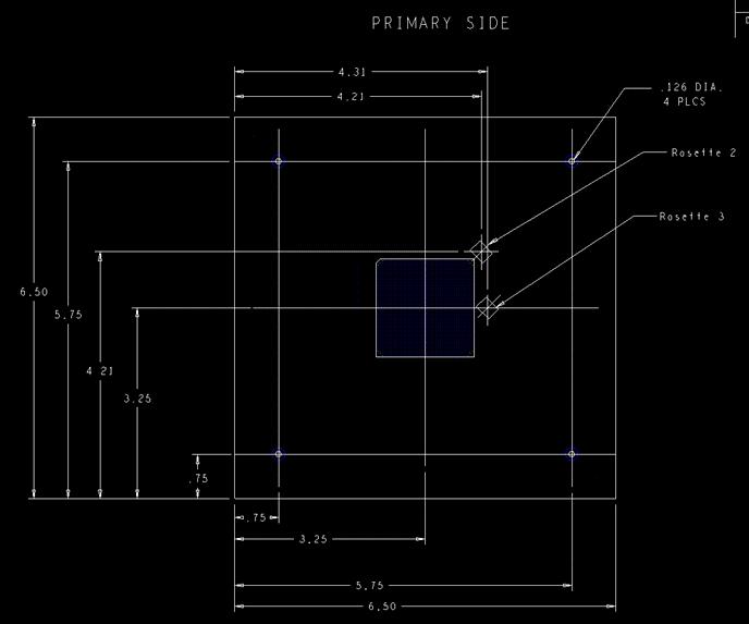
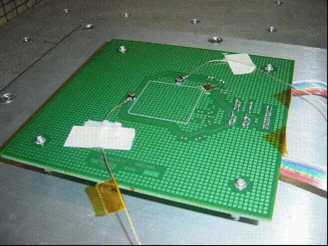
12 GEOMETRY
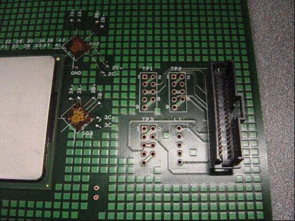
13 GEOMETRY

14 GEOMETRY Bottom side, viewed from top
15 GEOMETRY

16 SIMULATION SETUP ¼ symmetry model BGA package approximated with bulk material Material properties determined through modal analysis method 1% damping Strain & acceleration simulation results taken at single node nearest to sensor location ANSYS implicit solver
17 BOUNDARY CONDITIONS ¼ symmetry boundary conditions Fix UX,UY,UZ at exact fixture locations
 Mode Mode 1 0.")

18 MODAL ANALYSIS 1 Frequency (Hz) Period (s) Cumulative Mass Fraction (z-direction) Mode Mode Mode 3 Experimental data shows primary oscillating frequency = Hz. 0.1% Difference
19 LOADING CONDITIONS Loads as recorded on testing table Trapezoidal shock profile 50 G, 11ms
20 ACCELERATION Acceleration vs. Time Acel (G) time (s) ANSYS_Acel1 Acel1_Experimental Acel2_Experimental Table_Input_Experimental Acceleration = Second Derivative UZ + Table Input
21 STRAIN ROSETTE #1 Principal Strains, Rosette #1 3.0E E E-04 Strain 0.0E E E-04 time (s) Ros1_Emax Ros1_Emin ANSYS Ros1 1P ANSYS Ros1 3P Calculate Principal Strains (Plane Stress)
22 STRAIN ROSETTE #2 Principal Strains, Rosette #2 3.0E E E-04 Strain 0.0E E E E E-04 time (s) Ros2_Emax Ros2_Emin ANSYS Ros2 1P ANSYS Ros2 3P Calculate Principal Strains (Plane Stress)
23 STRAIN ROSETTE #3 Principal Strains, Rosette #3 2.0E E-04 Strain 0.0E E E E-04 time (s) Ros2_Emax Ros2_Emin ANSYS Ros3 1P ANSYS Ros3 3P Calculate Principal Strains (Plane Stress)
24 ERROR, ACCELERATION 11% Acel1 6% Acel2 2% avg First Peak, During Loading Acceleration vs. Time Fourth Peak, After Loading 6% Acel1 4% Acel2 3% avg Acel (G) time (s) ANSYS_Acel1 Acel1_Experimental Acel2_Experimental Table_Input_Experimental Difference = Experimental Simulation Experimental
25 ERROR, ROSETTE #1 44% First Peak (+) During Loading 1 st Principal Principal Strains, Rosette #1 3.0E E E-04 Strain 0.0E % First Peak (+) -1.0E-04 During Loading 3 rd Principal -2.0E-04 time (s) Ros1_Emax Ros1_Emin ANSYS Ros1 1P ANSYS Ros1 3P Fourth Peak (-) After Loading 1 st Principal Fourth Peak (-) After Loading 3 rd Principal 6% 34%
26 ERROR, ROSETTE #2 Principal Strains, Rosette #2 5% Fourth Peak (+) After Loading 1 st Principal 45% First Peak (-) During Loading 1 st Principal Insignificant: within noise range of strain gages Strain 3.0E E E E E Insignificant: within noise range of strain gages -2.0E E-04 Fourth Peak (+) After Loading 3 rd Principal 48% -4.0E-04 7% First Peak (-) During Loading 3 rd Principal time (s) Ros2_Emax Ros2_Emin ANSYS Ros2 1P ANSYS Ros2 3P
27 ERROR, ROSETTE #3 Principal Strains, Rosette #3 13% Fourth Peak (+) After Loading 1 st Principal 72% First Peak (-) During Loading 1 st Principal 2.0E E-04 Insignificant Strain 0.0E Insignificant -1.0E E-04 Fourth Peak (+) After Loading 3 rd Principal 65% -3.0E-04 11% First Peak (-) During Loading 3 rd Principal time (s) Ros2_Emax Ros2_Emin ANSYS Ros3 1P ANSYS Ros3 3P
28 SUMMARY Large strain gradients at rosette locations Rosette #1 is located on opposite side, dimensioned from chip, possible error source Rosette #1 difference (44%) is same magnitude as location difference of 1/8 inch on gradient Accelerometer 1,2 (avg) Rosette #1 Rosette #2 Rosette #3 During Loading 2% 44% 7% 11% After Loading 3% 34% 5% 13% Oscillating Frequency 0.1%
ScienceDirect. Response Spectrum Analysis of Printed Circuit Boards subjected to Shock Loads
 Available online at www.sciencedirect.com ScienceDirect Procedia Engineering 144 (2016 ) 1469 1476 12th International Conference on Vibration Problems, ICOVP 2015 Response Spectrum Analysis of Printed
MT06.11 Board level drop testing of PCB s
 MT06.11 Board level drop testing of PCB s John Kop, Gerben van den Oord, Dominic Swagemakers, Dennis van den Berg Coach: P. Schreurs, H. de Vries April 20, 2006 Contents Preface 3 1 Introduction 4 1.1
Modal and Harmonic Response Analysis of PBGA and S-N Curve Creation of Solder Joints
 Sensors & Transducers 2013 by IFSA http://www.sensorsportal.com Modal and Harmonic Response Analysis of PBGA and S-N Curve Creation of Solder Joints 1 Yu Guo, 1 Kailin Pan, 1, 2 Xin Wang, 1, 2 Tao Lu and
ADVANCED BOARD LEVEL MODELING FOR WAFER LEVEL PACKAGES
 As originally published in the SMTA Proceedings ADVANCED BOARD LEVEL MODELING FOR WAFER LEVEL PACKAGES Tiao Zhou, Ph.D. Southern Methodist University Dallas, TX, USA tiaoz@smu.edu Zhenxue Han, Ph.D. University
SOLDER JOINT RELIABILITY IN ELECTRONICS UNDER SHOCK AND VIBRATION USING EXPLICIT FINITE-ELEMENT SUB-MODELING. Sameep Gupte
 SOLDER JOINT RELIABILITY IN ELECTRONICS UNDER SHOCK AND VIBRATION USING EXPLICIT FINITE-ELEMENT SUB-MODELING Except where reference is made to the work of others, the work described in this thesis is my
Finite Element Static, Vibration and Impact-Contact Analysis of Micromechanical Systems
 Finite Element Static, Vibration and Impact-Contact Analysis of Micromechanical Systems Alexey I. Borovkov Eugeny V. Pereyaslavets Igor A. Artamonov Computational Mechanics Laboratory, St.Petersburg State
SHOCK AND VIBRATION RESPONSE SPECTRA COURSE Unit 1B. Damping
 SHOCK AND VIBRATION RESPONSE SPECTRA COURSE Unit 1B. Damping By Tom Irvine Introduction Recall the homework assignment from Unit 1A. The data.txt time history represented a rocket vehicle dropped from
Reliability analysis of different structure parameters of PCBA under drop impact
 Journal of Physics: Conference Series PAPER OPEN ACCESS Reliability analysis of different structure parameters of PCBA under drop impact To cite this article: P S Liu et al 2018 J. Phys.: Conf. Ser. 986
CHAPTER 8 FATIGUE LIFE ESTIMATION OF ELECTRONIC PACKAGES SUBJECTED TO DYNAMIC LOADS
 80 CHAPTER 8 FATIGUE LIFE ESTIMATIO OF ELECTROIC PACKAGES SUBJECTED TO DYAMIC LOADS 8. ITRODUCTIO Vibration environments can often involve millions of stress cycles because natural frequencies in electronics
Post Graduate Diploma in Mechanical Engineering Computational mechanics using finite element method
 9210-220 Post Graduate Diploma in Mechanical Engineering Computational mechanics using finite element method You should have the following for this examination one answer book scientific calculator No
Dynamic behaviour of electronics package and impact reliability of BGA solder joints
 Dynamic behaviour of electronics package and impact reliability of BGA solder joints Q YU1, H Kikuchil, S Ikedal, M Shiratoril, M Kakino2, N Fujiwara2 Department of Mechanical Engineering and Material
A Numerical Approach Towards the Correlation Between Ball Impact Test and Drop Reliability
 A Numerical Approach Towards the Correlation Between Ball Impact Test and Drop Reliability Chang-Lin Yeh*, Yi-Shao Lai Stress-Reliability Lab, Advanced Semiconductor Engineering, Inc. 26 Chin 3 rd Rd.,
Reliability Evaluation Method for Electronic Device BGA Package Considering the Interaction Between Design Factors
 Reliability Evaluation Method for Electronic Device BGA Package Considering the Interaction Between Design Factors Satoshi KONDO *, Qiang YU *, Tadahiro SHIBUTANI *, Masaki SHIRATORI * *Department of Mechanical
ALASKA ENERGY AUTHORITY AEA ENGINEERING FEASIBILITY REPORT. Appendix B8. Finite Element Analysis
 ALASKA ENERGY AUTHORITY AEA11-022 ENGINEERING FEASIBILITY REPORT Appendix B8 Finite Element Analysis Susitna-Watana Hydroelectric Project Alaska Energy Authority FERC Project No. 14241 December 2014 Seismic
The Increasing Importance of the Thermal Management for Modern Electronic Packages B. Psota 1, I. Szendiuch 1
 Ročník 2012 Číslo VI The Increasing Importance of the Thermal Management for Modern Electronic Packages B. Psota 1, I. Szendiuch 1 1 Department of Microelectronics, Faculty of Electrical Engineering and
ANALYSIS AND EXPERIMENT OF DYNAMIC CHARACTERISTICS OF ELECTRONIC DEVICE CHASSIS
 ANALYSIS AND EXPERIMENT OF DYNAMIC CHARACTERISTICS OF ELECTRONIC DEVICE CHASSIS HE QING, DU DONGMEI, JIANG XUCHAO Key Laboratory of Condition Monitoring and Control for Power Plant Equipment, Ministry
Extending Steinberg s Fatigue Analysis of Electronics Equipment Methodology to a Full Relative Displacement vs. Cycles Curve
 Extending Steinberg s Fatigue Analysis of Electronics Equipment Methodology to a Full Relative Displacement vs. Cycles Curve Revision C By Tom Irvine Email: tom@vibrationdata.com March 13, 2013 Vibration
Mechanical Analysis Challenges in Micro-Electronic Packaging
 Mechanical Analysis Challenges in Micro-Electronic Packaging Luke J. Garner, and Frank Z. Liang Intel Corporation Electrical and thermal performance enhancing features in modern integrated circuits have
Prediction of Encapsulant Performance Toward Fatigue Properties of Flip Chip Ball Grid Array (FC-BGA) using Accelerated Thermal Cycling (ATC)
 using Accelerated Thermal Cycling (ATC)") Prediction of Encapsulant Performance Toward Fatigue Properties of Flip Chip Ball Grid Array (FC-BGA) using Accelerated Thermal Cycling (ATC) ZAINUDIN KORNAIN 1, AZMAN JALAR 2,3, SHAHRUM ABDULLAH 3, NOWSHAD
Prediction of Encapsulant Performance Toward Fatigue Properties of Flip Chip Ball Grid Array (FC-BGA) using Accelerated Thermal Cycling (ATC) ZAINUDIN KORNAIN 1, AZMAN JALAR 2,3, SHAHRUM ABDULLAH 3, NOWSHAD
DROP TEST performance has been one of the key package
 1802 IEEE TRANSACTIONS ON COMPONENTS, PACKAGING AND MANUFACTURING TECHNOLOGY, VOL. 2, NO. 11, NOVEMBER 2012 Finite Element Modeling of System Design and Testing Conditions for Component Solder Ball Reliability
Impact of BGA Warpage on Quality. Mike Varnau
 Impact of BGA Warpage on Quality Mike Varnau 5-11-06 Contents What is a Ball in Cup Failure Case Study Background Problem Identification Solution Results Assembly Related Factors Causing Ball in Cup Component
Available online at ScienceDirect. XVII International Colloquium on Mechanical Fatigue of Metals (ICMFM17)
") Available online at www.sciencedirect.com ScienceDirect Procedia Engineering 74 ( 2014 ) 165 169 XVII International Colloquium on Mechanical Fatigue of Metals (ICMFM17) Fatigue of Solder Interconnects
Available online at www.sciencedirect.com ScienceDirect Procedia Engineering 74 ( 2014 ) 165 169 XVII International Colloquium on Mechanical Fatigue of Metals (ICMFM17) Fatigue of Solder Interconnects
Finite Element Analysis of Piezoelectric Cantilever
 Finite Element Analysis of Piezoelectric Cantilever Nitin N More Department of Mechanical Engineering K.L.E S College of Engineering and Technology, Belgaum, Karnataka, India. Abstract- Energy (or power)
Further research on the coupled Influence of Temperature and Stress Field to PCB' Modal
 2nd International Conference on Machinery, Electronics and Control Simulation (MECS 217) Further research on the d Influence of Temperature and Stress Field to PCB' Modal Qin Luo1, a,*, Ke Yao 1, 2, b
RAMS seminar. Vibration by Viggo Pedersen
 RAMS seminar Vibration by Viggo Pedersen Vibration and Machine Learning Features Label Predictive maintenance Probability of failure Remaining useful life Machine learning when: Complex process Large amounts
(Refer Slide Time: 1: 19)
") Mechanical Measurements and Metrology Prof. S. P. Venkateshan Department of Mechanical Engineering Indian Institute of Technology, Madras Module - 4 Lecture - 46 Force Measurement So this will be lecture
Mechanical Measurements and Metrology Prof. S. P. Venkateshan Department of Mechanical Engineering Indian Institute of Technology, Madras Module - 4 Lecture - 46 Force Measurement So this will be lecture
TABLE OF CONTENTS CHAPTER TITLE PAGE DECLARATION DEDICATION ACKNOWLEDGEMENT ABSTRACT ABSTRAK
 vii TABLE OF CONTENTS CHAPTER TITLE PAGE DECLARATION DEDICATION ACKNOWLEDGEMENT ABSTRACT ABSTRAK TABLE OF CONTENTS LIST OF TABLES LIST OF FIGURES LIST OF ABBREVIATIONS LIST OF SYMBOLS ii iii iv v vi vii
DYNAMIC RESPONSE OF BOX-TYPE SONAR STRUCTURE. Sameer Abdul Azeez and O.R.Nandagopan
 ICSV14 Cairns Australia 9-12 July, 2007 DYNAMIC RESPONSE OF BOX-TYPE SONAR STRUCTURE Sameer Abdul Azeez and O.R.Nandagopan Naval Physical & Oceanographic Laboratory, Kochi, India 682 021 tsonpol@vsnl.com
Boundary Condition Dependency
 Boundary Condition Dependency of Junction to Case Thermal Resistance Introduction The junction to case ( ) thermal resistance of a semiconductor package is a useful and frequently utilized metric in thermal
Appendix A Satellite Mechanical Loads
 Appendix A Satellite Mechanical Loads Mechanical loads can be static or dynamic. Static loads are constant or unchanging, and dynamic loads vary with time. Mechanical loads can also be external or self-contained.
WW25R ±1%, ±5%, 2W Metal plate low ohm power chip resistors Size 2512 (6432)
") WW25R ±1%, ±5%, 2W Metal plate low ohm power chip resistors Size 2512 (6432) Current Sensing Type Automotive AEC Q200 compliant *Contents in this sheet are subject to change without prior notice. Page
WW25R ±1%, ±5%, 2W Metal plate low ohm power chip resistors Size 2512 (6432) Current Sensing Type Automotive AEC Q200 compliant *Contents in this sheet are subject to change without prior notice. Page
WW25Q ±1%, ±5%, 1W Metal plate low ohm power chip resistors Size 2512 (6432)
") WW25Q ±1%, ±5%, 1W Metal plate low ohm power chip resistors Size 2512 (6432) Current Sensing Type Automotive AEC Q200 compliant *Contents in this sheet are subject to change without prior notice. Page
WW25Q ±1%, ±5%, 1W Metal plate low ohm power chip resistors Size 2512 (6432) Current Sensing Type Automotive AEC Q200 compliant *Contents in this sheet are subject to change without prior notice. Page
Chapter 5: Ball Grid Array (BGA)
") Chapter 5: Ball Grid Array (BGA) 5.1 Development of the Models The following sequence of pictures explains schematically how the FE-model of the Ball Grid Array (BGA) was developed. Initially a single
Chapter 5: Ball Grid Array (BGA) 5.1 Development of the Models The following sequence of pictures explains schematically how the FE-model of the Ball Grid Array (BGA) was developed. Initially a single
Mechanical Shock Testing for LIGA Materials Characterization
 Mechanical Shock Testing for LIGA Materials Characterization Vesta I. Bateman Alfredo M. Morales Principal Member of Technical Staff Sandia National Laboratories* P.O. Box 58, MS553 Albuquerque, NM 87185-553
Cyclic Bend Fatigue Reliability Investigation for Sn-Ag-Cu Solder Joints
 Cyclic Bend Fatigue Reliability Investigation for Sn-Ag-Cu Solder Joints F.X. Che* 1, H.L.J. Pang 2, W.H. Zhu 1 and Anthony Y. S. Sun 1 1 United Test & Assembly Center Ltd. (UTAC) Packaging Analysis &
Modal Analysis: What it is and is not Gerrit Visser
 Modal Analysis: What it is and is not Gerrit Visser What is a Modal Analysis? What answers do we get out of it? How is it useful? What does it not tell us? In this article, we ll discuss where a modal
Improving the Accuracy of Dynamic Vibration Fatigue Simulation
 Improving the Accuracy of Dynamic Vibration Fatigue Simulation Kurt Munson HBM Prenscia Agenda 2 1. Introduction 2. Dynamics and the frequency response function (FRF) 3. Using finite element analysis (FEA)
Finite Element Analysis Lecture 1. Dr./ Ahmed Nagib
 Finite Element Analysis Lecture 1 Dr./ Ahmed Nagib April 30, 2016 Research and Development Mathematical Model Mathematical Model Mathematical Model Finite Element Analysis The linear equation of motion
Study of Rupture Directivity in a Foam Rubber Physical Model
 Progress Report Task 1D01 Study of Rupture Directivity in a Foam Rubber Physical Model Rasool Anooshehpoor and James N. Brune University of Nevada, Reno Seismological Laboratory (MS/174) Reno, Nevada 89557-0141
Qualification Test Method and Acceptance Criteria
 Qualification Method and Acceptance Criteria The summary shown in following tables give brief descriptions of the various reliability tests. Not all of the tests listed are performed on each product and
Microelectronics Reliability
 Microelectronics Reliability 52 (2012) 735 743 Contents lists available at SciVerse ScienceDirect Microelectronics Reliability journal homepage: www.elsevier.com/locate/microrel Failure mechanism of FBGA
Assessment of the SMT assemblies and Improvements through Accelerated testing methods. SMTA Chapter Meeting 18 th Jan 2014, India
 Assessment of the SMT assemblies and Improvements through Accelerated testing methods SMTA Chapter Meeting 18 th Jan 2014, India 1 Contents SMT solder defects due Thermo-Mechanical stress- what and how!
Dynamics of structures
 Dynamics of structures 2.Vibrations: single degree of freedom system Arnaud Deraemaeker (aderaema@ulb.ac.be) 1 Outline of the chapter *One degree of freedom systems in real life Hypothesis Examples *Response
Experimental Modal Analysis of a Flat Plate Subjected To Vibration
 American Journal of Engineering Research (AJER) 2016 American Journal of Engineering Research (AJER) e-issn: 2320-0847 p-issn : 2320-0936 Volume-5, Issue-6, pp-30-37 www.ajer.org Research Paper Open Access
Dynamic Stress Analysis of a Bus Systems
 Dynamic Stress Analysis of a Bus Systems *H. S. Kim, # Y. S. Hwang, # H. S. Yoon Commercial Vehicle Engineering & Research Center Hyundai Motor Company 772-1, Changduk, Namyang, Whasung, Kyunggi-Do, Korea
Transactions on the Built Environment vol 22, 1996 WIT Press, ISSN
 A shock damage potential approach to shock testing D.H. Trepess Mechanical Subject Group, School of Engineering, Coventry University, Coventry CVl 5FB, UK A shock damage (excitation capacity) approach
Measurement of Structural Intensity Using an Angular Rate Sensor
 Measurement of Structural Intensity Using an Angular Rate Sensor Nobuaki OMATA 1 ; Hiroki NAKAMURA ; Yoshiyuki WAKI 3 ; Atsushi KITAHARA 4 and Toru YAMAZAKI 5 1,, 5 Kanagawa University, Japan 3, 4 BRIDGESTONE,
The Torsion Pendulum (One or two weights)
") The Torsion Pendulum (One or two weights) Exercises I through V form the one-weight experiment. Exercises VI and VII, completed after Exercises I -V, add one weight more. Preparatory Questions: 1. The
The Torsion Pendulum (One or two weights) Exercises I through V form the one-weight experiment. Exercises VI and VII, completed after Exercises I -V, add one weight more. Preparatory Questions: 1. The
BACKGROUND AND INTRODUCTION
 WAVE MECHANICS As applied to pile testing 1 BACKGROUND AND INTRODUCTION Wave Mechanics 2 1 HISTORIC TOOLS AND MATERIALS Timber piles Drop Hammers 10 Days for the Romans to build the bridge over the Rhine
Structural Dynamics. Spring mass system. The spring force is given by and F(t) is the driving force. Start by applying Newton s second law (F=ma).
 is the driving force. Start by applying Newton s second law (F=ma).") Structural Dynamics Spring mass system. The spring force is given by and F(t) is the driving force. Start by applying Newton s second law (F=ma). We will now look at free vibrations. Considering the free
Structural Dynamics Spring mass system. The spring force is given by and F(t) is the driving force. Start by applying Newton s second law (F=ma). We will now look at free vibrations. Considering the free
Response Spectrum Analysis Shock and Seismic. FEMAP & NX Nastran
 Response Spectrum Analysis Shock and Seismic FEMAP & NX Nastran Table of Contents 1. INTRODUCTION... 3 2. THE ACCELEROGRAM... 4 3. CREATING A RESPONSE SPECTRUM... 5 4. NX NASTRAN METHOD... 8 5. RESPONSE
Chapter 14 Oscillations. Copyright 2009 Pearson Education, Inc.
 Chapter 14 Oscillations 14-1 Oscillations of a Spring If an object vibrates or oscillates back and forth over the same path, each cycle taking the same amount of time, the motion is called periodic. The
Chapter 5. Vibration Analysis. Workbench - Mechanical Introduction ANSYS, Inc. Proprietary 2009 ANSYS, Inc. All rights reserved.
 Workbench - Mechanical Introduction 12.0 Chapter 5 Vibration Analysis 5-1 Chapter Overview In this chapter, performing free vibration analyses in Simulation will be covered. In Simulation, performing a
COMPARISON BETWEEN 2D AND 3D ANALYSES OF SEISMIC STABILITY OF DETACHED BLOCKS IN AN ARCH DAM
 COMPARISON BETWEEN 2D AND 3D ANALYSES OF SEISMIC STABILITY OF DETACHED BLOCKS IN AN ARCH DAM Sujan MALLA 1 ABSTRACT The seismic safety of the 147 m high Gigerwald arch dam in Switzerland was assessed for
Chapter 14 Oscillations
 Chapter 14 Oscillations If an object vibrates or oscillates back and forth over the same path, each cycle taking the same amount of time, the motion is called periodic. The mass and spring system is a
New Functions. Test mode and Specimen failure. Power cycle test system with thermal analysis capability using structure function.
 using structure function. (1) Page 1/5 Test mode and failure There are two modes in a power cycle test: Tj Power cycle that changes the junction temperature (Tj Temperature) inside of the power semiconductor
Structural Damage Detection Using Time Windowing Technique from Measured Acceleration during Earthquake
 Structural Damage Detection Using Time Windowing Technique from Measured Acceleration during Earthquake Seung Keun Park and Hae Sung Lee ABSTRACT This paper presents a system identification (SI) scheme
2008 International ANSYS Conference
 2008 International ANSYS Conference Study of Nonlinear Parametric Response in a Beam using ANSYS Satish Remala, John Baker, and Suzanne Smith University of Kentucky 2008 ANSYS, Inc. All rights reserved.
Structural System, Machines and Load Cases
 Machine-Induced Vibrations Machine-Induced Vibrations In the following example the dynamic excitation of two rotating machines is analyzed. A time history analysis in the add-on module RF-DYNAM Pro - Forced
MECHANICAL FAILURE OF A COMPOSITE HELICOPTER STRUCTURE UNDER STATIC LOADING
 MECHANICAL FAILURE OF A COMPOSITE HELICOPTER STRUCTURE UNDER STATIC LOADING Steven Roy, Larry Lessard Dept. of Mechanical Engineering, McGill University, Montreal, Québec, Canada ABSTRACT The design and
CAEFEM v9.5 Information
 CAEFEM v9.5 Information Concurrent Analysis Corporation, 50 Via Ricardo, Thousand Oaks, CA 91320 USA Tel. (805) 375 1060, Fax (805) 375 1061 email: info@caefem.com or support@caefem.com Web: http://www.caefem.com
On the difference between thermal cycling and thermal shock testing for board level reliability of soldered interconnections
 Microelectronics Reliability 47 (27) 444 449 www.elsevier.com/locate/microrel On the difference between thermal cycling and thermal shock testing for board level reliability of soldered interconnections
Measurement Techniques for Engineers. Motion and Vibration Measurement
 Measurement Techniques for Engineers Motion and Vibration Measurement Introduction Quantities that may need to be measured are velocity, acceleration and vibration amplitude Quantities useful in predicting
Strain and Force San José State University A. Mysore Spring 2009
 Strain and Force Strain Gage Measures strain as a change in length L, observed by change in resistance R, for a given resistivity ρ and cross-sectional area A. For elastic materials that follow Hooke s
EQUIVALENT FRACTURE ENERGY CONCEPT FOR DYNAMIC RESPONSE ANALYSIS OF PROTOTYPE RC GIRDERS
 EQUIVALENT FRACTURE ENERGY CONCEPT FOR DYNAMIC RESPONSE ANALYSIS OF PROTOTYPE RC GIRDERS Abdul Qadir Bhatti 1, Norimitsu Kishi 2 and Khaliq U Rehman Shad 3 1 Assistant Professor, Dept. of Structural Engineering,
Prognostics Assessment of Aluminum Support Structure on a Printed Circuit Board
 Prognostics Assessment of Aluminum Support Structure on a Printed Circuit Board Sony Mathew, Diganta Das, Michael Osterman, and Michael Pecht CALCE Electronic Products and Systems Center Department of
Lecture 19. Measurement of Solid-Mechanical Quantities (Chapter 8) Measuring Strain Measuring Displacement Measuring Linear Velocity
 Measuring Strain Measuring Displacement Measuring Linear Velocity") MECH 373 Instrumentation and Measurements Lecture 19 Measurement of Solid-Mechanical Quantities (Chapter 8) Measuring Strain Measuring Displacement Measuring Linear Velocity Measuring Accepleration and
MECH 373 Instrumentation and Measurements Lecture 19 Measurement of Solid-Mechanical Quantities (Chapter 8) Measuring Strain Measuring Displacement Measuring Linear Velocity Measuring Accepleration and
Exam tomorrow on Chapter 15, 16, and 17 (Oscilla;ons and Waves 1 &2)
") Exam tomorrow on Chapter 15, 16, and 17 (Oscilla;ons and Waves 1 &2) What to study: Quiz 6 Homework problems for Chapters 15 & 16 Material indicated in the following review slides Other Specific things:
Exam tomorrow on Chapter 15, 16, and 17 (Oscilla;ons and Waves 1 &2) What to study: Quiz 6 Homework problems for Chapters 15 & 16 Material indicated in the following review slides Other Specific things:
Shorter Field Life in Power Cycling for Organic Packages
 Shorter Field Life in Power Cycling for Organic Packages S. B. Park e-mail: sbpark@binghamton.edu Izhar Z. Ahmed Department of Mechanical Engineering, State University of New York at Binghamton, Binghamton,
Fatigue Crack Analysis on the Bracket of Sanding Nozzle of CRH5 EMU Bogie
 Journal of Applied Mathematics and Physics, 2015, 3, 577-583 Published Online May 2015 in SciRes. http://www.scirp.org/journal/jamp http://dx.doi.org/10.4236/jamp.2015.35071 Fatigue Crack Analysis on the
Shape Optimization of Revolute Single Link Flexible Robotic Manipulator for Vibration Suppression
 15 th National Conference on Machines and Mechanisms NaCoMM011-157 Shape Optimization of Revolute Single Link Flexible Robotic Manipulator for Vibration Suppression Sachindra Mahto Abstract In this work,
Effect of Angular movement of Lifting Arm on Natural Frequency of Container Lifting Mechanism using Finite Element Modal Analysis
 Effect of Angular movement of Lifting Arm on Natural Frequency of Container Lifting Mechanism using Finite Element Modal Analysis Khodu M Dhameliya, 2 Utpal V Shah, 3 Dhaval Makwana, 4 Mansi Yadav, 5 Ishankumar
Thermal Characterization of Packaged RFIC, Modeled vs. Measured Junction to Ambient Thermal Resistance
 Thermal Characterization of Packaged RFIC, Modeled vs. Measured Junction to Ambient Thermal Resistance Steven Brinser IBM Microelectronics Abstract Thermal characterization of a semiconductor device is
Dynamic analysis of a reinforced concrete shear wall with strain rate effect. Synopsis. Introduction
 Dynamic analysis of a reinforced concrete shear wall with strain rate effect Synopsis A simplified analysis method for a reinforced concrete shear wall structure considering strain rate effects is presented.
COURSE OUTLINE. Introduction Signals and Noise Filtering Sensors: Piezoelectric Force Sensors. Sensors, Signals and Noise 1
 Sensors, Signals and Noise 1 COURSE OUTLINE Introduction Signals and Noise Filtering Sensors: Piezoelectric Force Sensors Piezoelectric Force Sensors 2 Piezoelectric Effect and Materials Piezoelectric
Numerical modelling of induced tensile stresses in rock in response to impact loading
 Numerical modelling of induced tensile stresses in rock in response to impact loading M.T. Mnisi, D.P. Roberts and J.S. Kuijpers Council for Scientific and Industrial Research (CSIR): Natural Resources
Propagation of Uncertainty in Stress Estimation in Turbine Engine Blades
 Propagation of Uncertainty in Stress Estimation in Turbine Engine Blades Giorgio Calanni, Vitali Volovoi, and Massimo Ruzzene Georgia Institute of Technology Atlanta, Georgia and Charles Vining Naval Air
an alternative approach to junction-to-case thermal resistance measurements
 an alternative approach to junction-to-case thermal resistance measurements Bernie Siegal Thermal Engineering Associates, Inc. Introduction As more and more integrated circuits dissipate power at levels
Dynamic (Vibrational) and Static Structural Analysis of Ladder Frame
 and Static Structural Analysis of Ladder Frame") Dynamic (Vibrational) and Static Structural Analysis of Ladder Frame Ketan Gajanan Nalawade 1, Ashish Sabu 2, Baskar P 3 School of Mechanical and building science, VIT University, Vellore-632014, Tamil
Dynamic (Vibrational) and Static Structural Analysis of Ladder Frame Ketan Gajanan Nalawade 1, Ashish Sabu 2, Baskar P 3 School of Mechanical and building science, VIT University, Vellore-632014, Tamil
T1 T e c h n i c a l S e c t i o n
 1.5 Principles of Noise Reduction A good vibration isolation system is reducing vibration transmission through structures and thus, radiation of these vibration into air, thereby reducing noise. There
DYNAMIC CHARACTERISTICS OF A PARTIALLY FLUID- FILLED CYLINDRICAL SHELL
 DOI: 10.5516/NET.2011.43.2.167 DYNAMIC CHARACTERISTICS OF A PARTIALLY FLUID- FILLED CYLINDRICAL SHELL MYUNG JO JHUNG *1, SEON OH YU 1, and YEONG TAEK LIM 2 1 Safety Research Division, Korea Institute of
Prognostics implementation of electronics under vibration loading
 Available online at www.sciencedirect.com Microelectronics Reliability 7 (7) 89 856 www.elsevier.com/locate/microrel Prognostics implementation of electronics under vibration loading Jie Gu *, Donald Barker,
Statics. Phys101 Lectures 19,20. Key points: The Conditions for static equilibrium Solving statics problems Stress and strain. Ref: 9-1,2,3,4,5.
 Phys101 Lectures 19,20 Statics Key points: The Conditions for static equilibrium Solving statics problems Stress and strain Ref: 9-1,2,3,4,5. Page 1 The Conditions for Static Equilibrium An object in static
AN INTRODUCTION TO NUMERICAL METHODS USING MATHCAD. Mathcad Release 14. Khyruddin Akbar Ansari, Ph.D., P.E.
 AN INTRODUCTION TO NUMERICAL METHODS USING MATHCAD Mathcad Release 14 Khyruddin Akbar Ansari, Ph.D., P.E. Professor of Mechanical Engineering School of Engineering and Applied Science Gonzaga University
Numerical Modelling of Dynamic Earth Force Transmission to Underground Structures
 Numerical Modelling of Dynamic Earth Force Transmission to Underground Structures N. Kodama Waseda Institute for Advanced Study, Waseda University, Japan K. Komiya Chiba Institute of Technology, Japan
Microsemi Power Modules. Reliability tests for Automotive application
 Microsemi Power Modules Reliability tests for Automotive application on basis of AEC-Q101 SP module line 1/ 10 Introduction With reference to standard AEC-Q101, designed by Automotive Electronics Council
Shock robustness of Mobile devices with HDD. Jan Ruigrok
 Shock robustness of Mobile devices with HDD Jan Ruigrok 1 Content of this presentation 1. Introduction MP3-player 2. Development of new test method (pendulum) Requirements Solved problems 3. Robustness
DYNAMIC FAILURE ANALYSIS OF LAMINATED COMPOSITE PLATES
 Association of Metallurgical Engineers of Serbia AMES Scientific paper UDC:669.1-419:628.183=20 DYNAMIC FAILURE ANALYSIS OF LAMINATED COMPOSITE PLATES J. ESKANDARI JAM 1 and N. GARSHASBI NIA 2 1- Aerospace
SHOCK AND VIBRATION RESPONSE SPECTRA COURSE Unit 29. Shock Response Spectrum Synthesis via Wavelets
 SHOCK AND VIBRATION RESPONSE SPECTRA COURSE Unit 29. Shock Response Spectrum Synthesis via Wavelets By Tom Irvine Email: tomirvine@aol.com Introduction Mechanical shock can cause electronic components
Key words Lead-free solder, Microelectronic packaging, RF packaging, RoHS compliant, Solder joint reliability, Weibull failure distribution
 Solder Joint Reliability Assessment for a High Performance RF Ceramic Package Paul Charbonneau, Hans Ohman, Marc Fortin Sanmina Corporation 500 Palladium Dr. Ottawa, Ontario K2V 1C2 Canada Ph: 613-886-6000;
Vibro-Impact Dynamics of a Piezoelectric Energy Harvester
 Proceedings of the IMAC-XXVIII February 1 4, 1, Jacksonville, Florida USA 1 Society for Experimental Mechanics Inc. Vibro-Impact Dynamics of a Piezoelectric Energy Harvester K.H. Mak *, S. McWilliam, A.A.
EMEA. Liudmila Feoktistova Engineer Atomenergoproekt
 EMEA Liudmila Feoktistova Engineer Atomenergoproekt Dr. Adolf Birbraer, Atomenergoproekt Dr. Alexandr Roleder, Atomenergoproekt Dmitry Mikhaluk, St. Petersburg State Polytechnical University Finite element
D : SOLID MECHANICS. Q. 1 Q. 9 carry one mark each. Q.1 Find the force (in kn) in the member BH of the truss shown.
 in the member BH of the truss shown.") D : SOLID MECHANICS Q. 1 Q. 9 carry one mark each. Q.1 Find the force (in kn) in the member BH of the truss shown. Q.2 Consider the forces of magnitude F acting on the sides of the regular hexagon having
D : SOLID MECHANICS Q. 1 Q. 9 carry one mark each. Q.1 Find the force (in kn) in the member BH of the truss shown. Q.2 Consider the forces of magnitude F acting on the sides of the regular hexagon having
Noise reduction applied to a decanter centrifuge
 Noise reduction applied to a decanter centrifuge A.J. van Engelen DCT2009.069 Research report, research performed at University of Canterbury, New ealand New ealand Supervisor: Dr. J.R. Pearse University
Drop Impact Reliability Test and Failure Analysis for Large Size High Density FOWLP Package on Package
 2017 IEEE 67th Electronic Components and Technology Conference Drop Impact Reliability Test and Failure Analysis for Large Size High Density FOWLP Package on Package Zhaohui Chen, Faxing Che, Mian Zhi
Broadband Vibration Response Reduction Using FEA and Optimization Techniques
 Broadband Vibration Response Reduction Using FEA and Optimization Techniques P.C. Jain Visiting Scholar at Penn State University, University Park, PA 16802 A.D. Belegundu Professor of Mechanical Engineering,
Arbitrary Normal and Tangential Loading Sequences for Circular Hertzian Contact
 Arbitrary Normal and Tangential Loading Sequences for Circular Hertzian Contact Philip P. Garland 1 and Robert J. Rogers 2 1 School of Biomedical Engineering, Dalhousie University, Canada 2 Department
Higher-Order Finite-Element Analysis for Fuzes Subjected to High-Frequency Environments
 Higher-Order Finite-Element Analysis for Fuzes Subjected to High-Frequency Environments Stephen Beissel Southwest Research Institute sbeissel@swri.org; (210)522-5631 Presented at: The 60 th Annual Fuze
Chapter 4 Analysis of a cantilever
 Chapter 4 Analysis of a cantilever Before a complex structure is studied performing a seismic analysis, the behaviour of simpler ones should be fully understood. To achieve this knowledge we will start
Modal Analysis of Single Rectangular Cantilever Plate by Mathematically, FEA and Experimental
 Modal Analysis of Single Rectangular Cantilever Plate by Mathematically, FEA and Experimental Ashish R. Sonawane 1, Poonam S. Talmale 2 1Research scholar, Late G. N. Sapkal College of Engineering, Nashik,