Improved Subcell Model for the Prediction of Braided Composite Response
|
|
|
- Denis Johnson
- 6 years ago
- Views:
Transcription
1 NASA/TM AIAA Improved Subcell Model for the Prediction of Braided Composite Response Christopher R. Cater and Xinran Xiao Michigan State University, East Lansing, Michigan Robert K. Goldberg and Lee W. Kohlman Glenn Research Center, Cleveland, Ohio June 2013
2 NASA STI Program... in Profile Since its founding, NASA has been dedicated to the advancement of aeronautics and space science. The NASA Scientific and Technical Information (STI) program plays a key part in helping NASA maintain this important role. The NASA STI Program operates under the auspices of the Agency Chief Information Officer. It collects, organizes, provides for archiving, and disseminates NASA s STI. The NASA STI program provides access to the NASA Aeronautics and Space Database and its public interface, the NASA Technical Reports Server, thus providing one of the largest collections of aeronautical and space science STI in the world. Results are published in both non-nasa channels and by NASA in the NASA STI Report Series, which includes the following report types: TECHNICAL PUBLICATION. Reports of completed research or a major significant phase of research that present the results of NASA programs and include extensive data or theoretical analysis. Includes compilations of significant scientific and technical data and information deemed to be of continuing reference value. NASA counterpart of peer-reviewed formal professional papers but has less stringent limitations on manuscript length and extent of graphic presentations. TECHNICAL MEMORANDUM. Scientific and technical findings that are preliminary or of specialized interest, e.g., quick release reports, working papers, and bibliographies that contain minimal annotation. Does not contain extensive analysis. CONTRACTOR REPORT. Scientific and technical findings by NASA-sponsored contractors and grantees. CONFERENCE PUBLICATION. Collected papers from scientific and technical conferences, symposia, seminars, or other meetings sponsored or cosponsored by NASA. SPECIAL PUBLICATION. Scientific, technical, or historical information from NASA programs, projects, and missions, often concerned with subjects having substantial public interest. TECHNICAL TRANSLATION. Englishlanguage translations of foreign scientific and technical material pertinent to NASA s mission. Specialized services also include creating custom thesauri, building customized databases, organizing and publishing research results. For more information about the NASA STI program, see the following: Access the NASA STI program home page at your question to help@sti.nasa.gov Fax your question to the NASA STI Information Desk at Phone the NASA STI Information Desk at Write to: STI Information Desk NASA Center for AeroSpace Information 7115 Standard Drive Hanover, MD
3 NASA/TM AIAA Improved Subcell Model for the Prediction of Braided Composite Response Christopher R. Cater and Xinran Xiao Michigan State University, East Lansing, Michigan Robert K. Goldberg and Lee W. Kohlman Glenn Research Center, Cleveland, Ohio Prepared for the The 54th Structures, Structural Dynamics, and Materials Conference (SDM) cosponsored by AIAA, ASME, ASCE, AHS, and ASC Boston, Massachusetts, April 8 11, 2013 National Aeronautics and Space Administration Glenn Research Center Cleveland, Ohio June 2013
4 Acknowledgments The authors would like to thank the NASA Lewis Educational and Research Collaborative Internship Program for its support, as well as colleagues for their assistance and insight. These include Dr. Gary Roberts and Dr. Kelly Carney of NASA Glenn Research Center (GRC). The work was funded by the VSST project of the Aviation Safety Program. Trade names and trademarks are used in this report for identification only. Their usage does not constitute an official endorsement, either expressed or implied, by the National Aeronautics and Space Administration. Level of Review: This material has been technically reviewed by technical management. Available from NASA Center for Aerospace Information 7115 Standard Drive Hanover, MD National Technical Information Service 5301 Shawnee Road Alexandria, VA Available electronically at
5 Improved Subcell Model for the Prediction of Braided Composite Response Christopher R. Cater and Xinran Xiao Michigan State University East Lansing, Michigan Robert K. Goldberg and Lee W. Kohlman National Aeronautics and Space Administration Glenn Research Center Cleveland, Ohio Abstract In this work, the modeling of triaxially braided composites was explored through a semi-analytical discretization. Four unique subcells, each approximated by a mosaic stacking of unidirectional composite plies, were modeled through the use of layered-shell elements within the explicit finite element code LS-DYNA. Two subcell discretizations were investigated: a model explicitly capturing pure matrix regions, and a novel model which absorbed pure matrix pockets into neighboring tow plies. The in-plane stiffness properties of both models, computed using bottom-up micromechanics, correlated well to experimental data. The absorbed matrix model, however, was found to best capture out-of-plane flexural properties by comparing numerical simulations of the out-of-plane displacements from single-ply tension tests to experimental full field data. This strong correlation of out-of-plane characteristics supports the current modeling approach as a viable candidate for future work involving impact simulations. 1.0 Introduction Triaxially braided composites have been implemented into fan containment systems for jet engines due to the high-specific stiffness and strength of fiber-reinforced polymer matrix systems and the improved impact damage tolerance and delamination resistance of braided architectures. These types of composites, however, present significant disadvantages for numerical modeling and simulation. First, previous impact studies have shown architectural dependence on damage evolution and damage patterns during a ballistic impact event (Ref. 1). Consequently, an appropriate modeling strategy must account for the nonhomogeneity present at the mesoscale: the scale of the braided pattern. Second, standardized coupon testing used for metals and simpler composite architectures have been shown to be relatively ineffective for determining braided composite strength properties (Ref. 2). Thus, accurate strength properties required for standard finite element composite damage models are currently unavailable. Additionally, the modeling scheme must be computationally efficient in order to be suitable for modeling of dynamic events such as a fan-blade-out event. The current work presented proposes to improve on already developed semi-analytical methods utilizing layered-shell elements and existing composite material models within the explicit finite element code LS-DYNA (Ref. 3). The overall goal is to develop a modeling algorithm which can best capture mechanisms of deformation and damage unique to the braided reinforcement architecture. Analytical methods for determining the elastic properties of braided composites utilizing micromechanics were first developed as an extension of previous literature on woven composites. These typically involved first identifying the repeating unit cell, RUC, of the braided mesostructure. Ishikawa and Chou developed mosaic, fiber undulation and bridging models, modifying classical laminate theory to account for fiber undulations (Refs. 4 and 5). Naik and Shembekar (Refs. 6 and 7) extended the onedimensional mosaic model into two dimensions, whereas Yang et al. (Ref. 8) improved on accounting for fiber undulation in a fiber inclination model. Branch et al. (Ref. 9) extended a fiber inclination model into three dimensions. Redman and Douglas (Ref. 10) implemented the mosaic model using the rule of NASA/TM
6 mixtures and classical lamination plate theory (CLPT). More advanced discretizations of the RUC were developed by Ivanov and Tabei (Refs. 11 to 13), splitting it into four unique subcells. Huang (Refs. 14 to 16) developed a micromechanical model modeling individual subcells as regions of two yarns and two pure matrix regions and treating each as a unidirectional (UD) composite. Quek et al. (Ref. 17) developed an analytical model which consisted of one axial tow, two braider tows, and one matrix layer. Concentric cylinder modeling was used to determine the homogeneous properties of the RUC. Carey et al. (Ref. 18) divided the braided RUC into 13 distinct regions and utilized a volume weighted stiffness matrix to homogenize the properties of the RUC. It was noted in Masters et al. (Ref. 19) that simple analytical laminate models performed well for stiffness predictions, whereas Falzon (Ref. 20) noted that these representations were unable to accurately capture out-of-plane properties. There are three classifications of numerical methods for predicting the response of triaxially braided composites. The first includes those which model the RUC explicitly through finite element (FE) models (Refs. 21 to 23). In these approaches, the explicit models are used to determine the effective properties (stiffness/strength) of the RUC for use in structural simulations. A review of these types of numerical methods can be found in (Ref. 24). A second branch utilizes multiscale methodologies to link the explicit FE representation of the RUC with homogenized elements on the structural level (Ref. 25). Lastly, a semi-analytical method was developed (Refs. 26 and 27) based on a braiding-through-the-thickness method introduced by Cheng and Binienda (Ref. 28) utilizing layered shell elements, subcell discretizations, and the inherent CLPT implementation available in FE packages. Xiao et al. (Ref. 29) utilized a similar layered shell methodology with a unique subcell discretization. In the current work, the semi-analytical methodology is utilized and builds upon limitations in the previous models by Cheng and Binienda (Ref. 28) and Xiao et al. (Ref. 29). Section 2.0 will discuss the general methodology in the semi-analytical approach using subcell models and introduce the novel absorbed matrix model. Section 3.0 will cover the numerical implementation of the modeling procedure and Section 4.0 will verify the in-plane elastic properties of the subcell models. Finally, the efficacy of the absorbed matrix model will be demonstrated with novel simulations of single-ply transverse tension tests in Section Subcell Modeling 2.1 Previous Works The material system of interest is a [0/+60/ 60] triaxially braided composite made of 24 k carbon fiber bundles in the 0 tow direction and 12 k carbon fiber bundles in the 60 braider directions. Braider geometries were formed by A&P Technologies and RTM molding was done by North Coast Composites (Refs. 1, 2, and 30). Fiber and matrix constituent sources and properties are provided in Section 3.1. A typical RUC, the smallest characteristic volume capturing the effective properties of this braided composite, is shown in Figure 1(a). The unit cell can be decomposed into 4 subcells as outlined in Figure 1(b). This partitioning corresponds to the existence of regions where axial (0 ) and braider (+60 / 60 ) tows are both present and regions where only the braider tows are present. Figure 1(b) only displays the fiber tows in the braided composite and not the pure matrix regions which exist between and around fiber tows. The boundary of subcells A and C are drawn to lie at the edges of axial fiber tows. The individual subcells can be subsequently discretized in a mosaic model of UD composite plies to capture the orientation and response of the fiber tows within the triaxial braid. Previous subcell modeling (Refs. 26 to 28, and 30) developed in collaboration with the NASA Glenn Research Center (GRC) and the University of Akron, shown in Figure 2(a), utilized subcells containing two unique UD plies: one containing the axial tow, and another containing the braider tow and surrounding matrix material. The two UD plies were assigned unique fiber volume fractions. These volume fractions were determined by matching global fiber volume fractions and assuming 80 percent fiber volume fraction in the 0 plies. The fiber volume fraction of the axial tows in this braided composite have been previously assumed to be 80 percent (Ref. 26). NASA/TM
.")
.")
7 There were two limitations to these previous models which are addressed in this work. First, the latest revision of the semi-analytical model homogenized each subcell through the thickness, resulting in a single layer for each subcell (Ref. 27). Although the model was still able to capture in-plane stiffness and strength properties of the braided composite, unique flexural properties of individual subcells were lost, such as the unique tension-twist coupling of the unsymmetric subcell laminate documented by Kohlman (Ref. 2). Secondly, the fiber volume fraction of the 60 UD plies in the model in Figure 2(a) were determined by meeting the global composite fiber volume fraction, but did not reflect the actual fiber volume fraction contained in the given subcells. The subcell model developed by Xiao et al. (Ref. 29) overcame these limitations by retaining the layered shell formulation for each individual subcell as well as developing a simple straight line model for determining ply thicknesses and UD fiber volume fractions. Xiao et al. also modeled fiber tows as unique UD plies, where the fiber volume fraction of each ply was identical to that of the fiber tow (~80 percent) and pure matrix pockets were modeled explicitly using the resin properties. Figure 2(b) displays the discretization, which hereon is referred to as the pure matrix model. Another significant advantage to the NASA/TM
![discretization of the pure matrix model was that the B and D subcells containing only the braider tow plies were modeled as symmetric [ 60 /+60 / 60 ] and [+60 / 60 /+60 ] laminates.](/docs-images/74/69903054/images/8-0.jpg "Figure 3 shows a detailed schematic highlighting the overlapping of +60 and 60 tows in subcells B and D.")

8 discretization of the pure matrix model was that the B and D subcells containing only the braider tow plies were modeled as symmetric [ 60 /+60 / 60 ] and [+60 / 60 /+60 ] laminates. Figure 3 shows a detailed schematic highlighting the overlapping of +60 and 60 tows in subcells B and D. Although the orientation of the overlap differs between the subcells, they both contain equal amounts of 60 and -/+ 60 tow regions within the entire subcell. Although the local green/yellow triangular regions on the braid are locally unsymmetric, one can approximate that these two subcells are symmetric with respect to the subcell discretization. A limitation of the pure matrix model, however, is the fact that the pure matrix pockets contained between the UD plies do not accurately represent the true interaction of pure resin pockets with adjacent fiber tows. Figure 4 presents a cross-sectional micrograph of the braided composite with a red arrow indicating a pure matrix region adjacent to an axial fiber tow and a green arrow indicating matrix rich regions between axial and braider tows. From the micrograph images, more pure matrix regions are found lying in-plane to either the braider or axial tow rather than sandwiched between braider and axial tows as is modeled in the pure matrix model in Figure 2(b). Despite this deficiency, the pure matrix model is used as a comparative reference to a new absorbed matrix model. 2.2 Absorbed Matrix Model In an attempt to combine aspects of both the previous semi-analytical models with that of the pure matrix model, it was decided that a suitable subcell discretization would contain the following elements: 1. Explicit modeling of UD layers 2. Accurate subcell fiber volume fractions 3. Symmetric B/D subcells 4. Better matrix representation The absorbed matrix model utilizes the straight line model used by Xiao et al. for determining fiber volumes in each subcell for the axial and braider directions. Rather than modeling pure matrix pockets as unique layers which are in parallel (that is, with respect to in-plane loading) to the UD fiber tow plies, the volume of pure matrix is absorbed by the surrounding UD fiber tow plies to create a homogenized representation of the tow/matrix interaction. This representation of the tow/matrix interaction is notably similar to the original subcell model in Figure 2(a), however, the fiber volume fraction of the braider plies in this model are now thought to best capture the amount of fibers in the respective subcells. Figure 5 compares the fiber volume fractions between the previous semi-analytical subcell models and those of the NASA/TM
 for subcells A and B and fiber volume fractions segregated by direction (red and green).")
9 pure matrix and absorbed matrix models. Both the pure and absorbed matrix models have similar volume fractions since they are derived based on the same straight line model approach. Figure 5 shows fiber volume fraction totals (blue) for subcells A and B and fiber volume fractions segregated by direction (red and green). It should be noted that the volume fractions shown for the axial and braider plies are given with respect to the volume of the subcell, thus are not ply-level fiber volume fractions discussed later. The geometric parameters required to use the straight line model for this braided composite system are given in Table 1. Both the pure matrix model and the absorbed matrix model are applied in the sections to follow for testing both in-plane stiffness properties and single ply coupon tests. The resulting subcell discretizations are presented in Tables 2 and 3, respectively. The necessary equations and figures for the straight line model used for computing the thicknesses in Tables 2 and 3 are presented in the Appendix. The thicknesses in Tables 2 and 3 are with respect to a total shell thickness of unity. It should be noted that the absorbed matrix model assumes that pure matrix pockets in subcells A and C are assimilated only into the 60 plies. Thus, the axial UD ply in subcells A and C has a fiber volume fraction of 80 percent for both the pure matrix and absorbed matrix models. The next section will cover the numerical implementation of both models within LS-DYNA. TABLE 1. GEOMETRICAL PARAMETERS USED FOR CALCULATING THE LAMINA THICKNESSES (T700/PR520 SYSTEM) Label Description Value W Width of RUC (m) W A Width of cell A (m) W B Width of cell B (m) h Ply thickness (m) V f,ud Fiber volume (tow) 0.8 n a Number of fibers in axial tow n b Number of fibers in braider tow d a Diameter of fiber filament in axial tow (m) d b Diameter of fiber filament in the braider tow (m) L Height of unit cell (length) (m) θ Braid angle (degrees) 60 NASA/TM
10 TABLE 2. SUBCELL A & B DISCRETIZATION FOR THE PURE MATRIX MODEL Subcell A Lay-up Angle, V f, Thickness degree percent Braider tow Matrix Axial tow Matrix Braider tow Subcell B Lay-up Braider tow Matrix Braider tow Matrix Braider tow TABLE 3. SUBCELL A AND B DISCRETIZATION FOR THE ABSORBED MATRIX MODEL Subcell A Lay-up Angle, Vf, Thickness degrees percent Braider tow Axial tow Braider tow Subcell B Lay-up Braider tow Braider tow Braider tow Numerical Implementation 3.1 Material Models The work presented here focuses on single-ply coupon tests which remained within the elastic range of the composite, thus all plies in both subcell models required only elastic properties. However, in preparation for future work to identify a top-down approach for determining ply-level strength, viable candidates for material models were investigated and utilized in the work. The matrix material was assumed to be elastic, perfectly-plastic and was implemented within LS-DYNA using material type 24, *MAT_PIECEWISE_LINEAR_PLASTICITY. The matrix properties were taken from Table 4. The efficacy of the elastic, perfectly-plastic assumption was not validated here, and it should be noted that the explicit modeling of the matrix was not necessary for the absorbed matrix model. Two resident material models of LS-DYNA were identified as candidates for modeling the unidirectional composite material: Mat_54, a linear-elastic composite damage model, and Mat_58, a non-linear composite model utilizing a continuum damage mechanics (CDM) approach. The former utilizes the Chang-Chang failure criterion and models elastic/brittle failure in the fiber direction and an elastic, perfectly-plastic response in the transverse and shear matrix directions. The latter model uses a modified-hashin failure criterion and a strain-driven CDM formulation developed by Matzenmiller (Ref. 31). A purely elastic composite response was simulated by setting arbitrarily high strength values in Mat_58 for all directions in the composite damage model, thereby requiring only updated elastic properties. For these stiffness values, a bottom-up micromechanics approach was employed to calculate the moduli and Poisson s ratio of the unidirectional layers in each of the subcells. In this way, the effective properties of the UD ply were determined based on the constituent properties of the fiber and matrix. The micromechanics software MAC/GMC developed at NASA GRC (Ref. 32) was used to compute the effective properties (elastic moduli, Poisson ratio) of the UD lamina based on the constituent properties provided in Table 4. It was hypothesized to be sufficient to use this bottom-up approach since the UD discretization of the sub-cell accurately captured the fiber contributions in all material axes present in the braided composite NASA/TM
.")
11 E11, TABLE 4. CONSTITUENT MATERIAL PROPERTIES (REFS. 26 TO 28 AND 33) Material Density, E22, Poisson, G12, g/cm 3 GPa GPa v12 GPa T PR E (particularly for in-plane loading). The process of determining the UD lamina properties was repeated depending on the number of UD fiber volume fractions present in the discretization. For example, the absorbed matrix model would involve computing effective properties using MAC/GMC for 37.5, 73, and 80 percent fiber volume fractions. The layered shell formulation within LS-DYNA would use laminate theory to determine the overall subcell response based upon the provided UD properties. This bottom-up process was used to compute the UD ply properties for four different material systems (T700 Toray fibers with different matrix systems: Cytec PR520, Cytec 5208, Hexcel 3502, Epon Epikote Resin 862, hereby referred to as E-862). 3.2 Finite Element Model This section highlights the implementation of the layered subcell approach for modeling the braided composite within the FE code, LS-DYNA. Each of the individual subcells were modeled as unique parts composed of a layered, Belytschko-Tsay quadrilateral shell using the *INTEGRATION_SHELL keyword. Each layer was assigned a unique integration point and associated thickness according to the parameters provided in Table 2. Tensile coupon tests were simulated in both the axial direction (parallel to the axial tows) and the transverse direction (perpendicular to the axial tows). Axial coupon specimen geometries were 8 by by in. (H by W by D, w/240 elements) whereas the transverse coupon geometries were by 1.4 by in. (476 elements). These dimensions corresponded to a 6-ply specimen of the braided composite. Each shell element thus represented 6 plies of the braided composite and the total thickness of the shell was set to in. It should be noted that in the real composite braid, nesting of axial fibers occurs and results in imperfect stacking. These effects are currently neglected and perfect layer stacking is assumed. The finite element models for the tensile tests are provided in Figure 6. The compression specimen geometries were 1 by by in. and 1.4 by by in. (H by W by D) for the axial and transverse compression tests, respectively. The meshes for the axial and transverse compression tests used to compute the compressive moduli are shown by highlighted boxes in Figure 6. A white arrow in Figure 6, and in figures to follow, identifies the direction of the axial fiber tows. NASA/TM
12 4.0 Coupon Test Results The finite element results from the simulated coupon tests were used to compute effective properties of the braided composite for various matrix systems. Cross-sectional forces acting at the center gage of the specimen are used to compute the uniaxial stresses, whereas crosshead displacements are used for strain calculations. The stress-strain curves are then used to compute the moduli for the axial and transverse directions in both tension and compression. Table 5 displays the results for the E-862 and 3502 material systems. Shown are the predicted moduli for the pure matrix model, absorbed matrix model, previous subcell models (where available), and experimental test data. Table 6 presents similar data for the PR520 and 5208 material systems. General trends in the moduli predictions were that the axial tensile stiffnesses were slightly over-estimated (~2.4 percent) and the transverse tensile stiffnesses were generally under-predicted (~18 percent). Despite little variation in the experimental transverse moduli across the material systems, the simulations were sensitive to the matrix modulus. The pure matrix model was slightly stiffer in all cases, due to the localization of the fibers in the 80 percent UD plies and its inherent effect on the subcell response. Both investigated subcell models adequately captured the stiffness properties even when compared against previous subcell works listed for the E-862 and PR520 systems in Tables 5 and 6. The results for the compressive moduli varied across the material systems and between the transverse and axial directions. The transverse compression moduli were generally in better agreement (~6 percent), however, the axial compression moduli were only slightly over-predictive (~13 percent). For the case of compression, a similar trend in matrix moduli sensitivity was found for the transverse case, and an apparent softening in the absorbed matrix model in comparison to the pure matrix model was noticeable. Considering the purely predictive, bottom-up method of the proposed subcell models the moduli predictions were well within a reasonable range. Both the pure matrix and absorbed matrix models are investigated for their out-of-plane properties and verified against single ply coupon tests in the next section. TABLE 5. COMPARISONS OF COMPUTED MODULI WITH EXPERIMENTAL DATA FOR THE E-862 AND HEXCEL 3502 MATERIAL SYSTEMS E Pure matrix Absorbed matrix Previous works, (Ref. 30) Test, (Ref. 34) Pure matrix Absorbed matrix E11T (GPa) E22T (GPa) E11C (GPa) E22C (GPa) Test, (Ref. 30) TABLE 6. COMPARISONS OF COMPUTED MODULI WITH EXPERIMENTAL DATA FOR THE CYTEC 5208 AND PR520 MATERIAL SYSTEMS 5208 PR520 Pure matrix Absorbed matrix Test (Ref. 34) Pure matrix Absorbed matrix Previous works (Refs. 30 and 27) E11T(GPa) / E22T (GPa) / E11C (GPa) E22C (GPa) Test (Ref. 34) NASA/TM
13 5.0 Single Ply Coupon Tests and Simulations Previous works have investigated the out-of-plane displacements in single-ply coupon tests of the braided composite under axial and transverse tension (Ref. 2) using Digital Image Correlation (DIC) on the T700/E862 braided composite. The displacements were a result of the locally unsymmetric nature of the braided composite. The DIC images of the out-of-plane displacements are reproduced in Figures 7(a) and (b). In light of these results, it was conjectured that a modeling approach best capturing this phenomenon would be advantageous for two reasons. One, it would provide a means of quantifying the flexural property predictions of the subcell model. Second, it would suggest that the subcell model may be sufficient in capturing the effects of inter-ply delamination hypothesized to be caused by these out-ofplane deformations. These edge-related delaminations drastically affect the stress/strain distribution in the gage section of standard test coupons (Ref. 2) and accurate simulations of these phenomena may provide insight into obtaining valuable strength data from material characterization tests. 5.1 Subcell Flexural Properties CLPT was used initially to determine the anticipated response of the two subcell discretizations (pure matrix and absorbed matrix models). This analysis would provide insight into the out-of-plane properties of the subcells and would allow for meaningful interpretation of the single ply coupon simulations. Two subcell characteristics were identified as potential contributors to the out-of-plane deformations and studied using CLPT: the tension/twist coupling of subcells A and C and the flexural modulus of subcell B and D. To quantify the tension twist coupling under uniaxial loading, relations (1) and (2) below were used- whereby assumptions of uniaxial stress and zero membrane moments provided a relation between membrane strain, ε x or ε y, and the twist curvature, k xy. The x-direction corresponds to that of the axial tows (0 ), and the y-direction corresponds to the transverse direction perpendicular to the axial tows. Equation (1) represents the tension-twist coupling for uniaxial tension in the x-direction. Conversely, Equation (2) is used for the case of uniaxial tension in the y-direction. The quantities T * x and T * y represent the linear relation between membrane strain and curvature for the cases of uniaxial loading in the axial and transverse directions, respectively. The quantities B 16 and B 26 are the only non-zero components of the extensional-bending coupling matrix of the subcell laminate; it is for this reason the curvatures are reduced to only k xy for the case of uniaxial tension. The computed results for the two discretization k k 0 xy 0 xy A A A A B 26 D B 16 D B B x T x 0 y T y x y (1) (2) f 1 12 Eij,for i, j1,2 (3) * 3 1 d h ij D ij NASA/TM
 (GPa) (GPa) Pure matrix 9.48 21.37 7.91 Absorbed matrix 6.53 21.01 10.4 TABLE 9.")
14 TABLE 7. TENSION TWIST COUPLING IN SUBCELL A Model * T x (1/m) * T y (1/m) Pure matrix Absorbed matrix TABLE 8. PREDICTED FLEXURAL MODULI OF SUBCELL B Model E f x E f y E f xy (GPa) (GPa) (GPa) Pure matrix Absorbed matrix TABLE 9. COMPARISON OF BENDING STIFFNESS MATRICES FOR SUBCELL B Pure matrix model Absorbed matrix model models, shown in Table 7, highlight the minute differences between the pure and absorbed matrix models in terms of the quantities T * x and T * y. The flexural moduli of subcell B for the two discretizations were computed using Equation (3) and the results are presented in Table 8. The flexural moduli in the x and xy directions varied considerably between the subcell discretizations, however the flexural moduli for the transverse, y, direction were nearly identical for both models. This similarity in transverse flexural moduli was contrary to the unambiguously different D matrices (bending-stiffness matrices) computed for the two methodologies, shown in Table Numerical Verification of Single Subcell Responses The curvatures seen in Figure 7(a) and (b) were hypothesized to be a direct consequence of the tension-twist coupling present in the unsymmetric subcells A and C. Thus, it was necessary to ensure the LS-DYNA implementation of the subcell models captured this phenomenon and to determine any mesh and/or element-type dependencies. Due to little expected differences between the two subcell discretizations in the tension/twist responses of subcells A and C, only the pure matrix model was used in the simulations to follow and shown in Figures 8 and 9. Figure 8(a) and (b) present the contour plots of out-of-plane displacement for subcell A under uniaxial tension. As can be seen from the contours, the displacements in the y and z directions were unrestrained. There was noticeable smoothing in the contours NASA/TM

.")
15 as a function of increased mesh dependency; however, the size and magnitude of the deformation were unchanged. The out-of-plane deformations were as expected from the laminate analysis reported previously with only twist curvature, k xy, present in the case of uniaxial tension. The various contour plots in Figure 9 for subcell C highlight the effects of edge boundary conditions on the displacements as well as the influence of shell element formulation. Two shell formulations were investigated, Belytschko-Tsay and Belytschko-Leviathan, based on recommendations in literature for modeling unbalanced and unsymmetric lamina in LS-DYNA (Ref. 35). In the case of free y and z displacements on the top and bottom surfaces of the subcell, the two element formulations produced nearly identical results. When the y and z displacements were fixed on the top and bottom boundaries, a reversal in twist was observed. Due to the complex nature of the induced curvatures, only Belytschko-Leviathan shells obtained smooth contour plots seen in Figure 9(d). In contrast, the Belytschko-Tsay elements had noticeable sharp, lined features which appear to be a function of the element size, highlighted in Figure 9(c). It should also be NASA/TM

16 mentioned that comparing Figure 9(a) with Figure 8(a) indicates that the out-of-plane deformation of subcells A and C have reflective symmetry with respect to each other. Based on the performance of the Belytschko-Leviathan shells, it was deemed that the LS-DYNA layered shell implementation of the subcell discretizations were sufficient to capture the necessary tension-twist mechanisms. Belytschko- Leviathan shell elements are utilized in the single ply coupon simulations to follow. 5.3 Single Ply Coupon Simulations Full coupon simulations were performed for both axial and transverse tension using similar coupon dimensions from the earlier tensile specimens. In this study, the thicknesses of the shells were reduced to that of a single ply (~0.022 in.). The coupon mesh was refined to include 4 elements per subcell, shown in Figure 10(b), in comparison to that of the standard coupon tests in Figure 6(a) and (b). Belytschko Leviathan shell elements are used to better account for the tension-twist coupling of the unsymmetric subcells as discussed in the previous section. Both coupon specimens are loaded to 1 percent strain for which the composite response in the experiments was purely elastic. Thus, the currently elastic material models for the UD plies in each subcell are again deemed appropriate for capturing the out-of-plane effects. Transverse coupon results are displayed in Figure 10(a) and (c) for the pure matrix model and can be compared to mesh/subcell location using Figure 10(b). The two contour plots in Figure 10(a) and (c) represent two alternating stable positions in the predicted solution, which tend to alternate through loading. Figure 10(a) contained the major curvatures and displayed similarities to the DIC results in Figure 7(a). Minor curvatures of opposite sign seen in Figure 10(c) also existed between the major curvatures that could be observed in the DIC data. Two distinct remarks could be made, qualitatively, NASA/TM

17 from the contour results. First, edge twisting resulted from a collective effect of subcells A and C and the reflective symmetry of their tension-twist coupling. Consequently, significant edge displacements, although rooting from the twisting of subcells A and C, were manifested in subcells B and D. In Figure 10(c), the major curvatures occurred in the regions of subcell B, whereas the minor curvatures occurred within subcells D. This feature was determined to be a consequence of boundary conditions and the relative adjacency of either of these subcells with the restrained edge. For example, modifying the order of subcells so that subcell C would be the first from the constrained edge that is, if looking left to right in Figure 10(b) would move the location of the major curvatures to subcells D. This shifting of subcells was performed and the single ply transverse tension simulation is given in Figure 11. The z-displacement contours shown in Figure 11 provide an example of competing major/minor curvatures between subcell B and D by varying the subcell closest to the restrained edge (labeled on the figure). The left hand side of Figure 11 features dominant positive (red) displacement curvatures at the top of the model, whereas beyond the dashed transitional region marked on the figure the dominant displacement curvatures at the top of the model are negative (blue). Though the source of major/minor curvatures was found to be a function of boundary condition, the alternating stable contours between those in Figure 10(a) and (c) were thought to be a construct of the numerical implementation. The contours seen experimentally were entirely stable and matched closely to that of Figure 10(c), and thus supported this deduction. These results highlight the importance of the finite element model s constraints on the out-ofplane displacement contours in the modeling approach, a phenomenon which must be acknowledged when comparing experimental and numerical results. A quantitative comparison of the z-displacements for the two subcell models is displayed in Figures 12(a) to (c) with the full field DIC data presented again in Figure 12(d). The results are presented using the stable contour shape from Figure 10(c), which are found to match closely to those seen experimentally. Two different element sizes are provided for the absorbed matrix model, Figure 12(a) and (b), to show the effect of a mesh refinement on smoothing the displacement contours. Note that all four contour plots match to the fringe levels shown at the right of Figure 12. As expected from the single subcell tests, the finer discretization, although smoothing the contours, did not alter the magnitude of the z-displacements. Comparing the two subcell models, the pure matrix model showed a significant reduction in out-of-plane deformation. Despite the pure matrix model showing qualitatively accurate curvatures in Figures 10 and 11, the contours were underpredicted in comparison to the experimental results. Based on the earlier investigations using CLT, the probable cause of the suppression of the out-ofplane displacements in the pure matrix model was the divergent properties of the bending stiffness matrix components between the two discretizations. The pure matrix model had a 145 percent higher flexural modulus in the axial fiber direction than the absorbed matrix counterpart, despite there being almost no differences in the tension-twist coupling of subcell A between the two models. Thus, the stiff outer UD plies in subcell B of the pure matrix model are acting like composite sandwich skin layers, suppressing the outof-plane deformation. The z-displacements predicted by the absorbed matrix model for both element discretizations in Figure 12(a) and (b) were in good agreement with the experimental results in Figure 12(d). NASA/TM
.")
18 The z-displacement contour plots for axial coupon simulations are shown in Figure 13. The axial coupon was meshed coarsely with two elements per subcell width, similar to that of the transverse case shown in Figure 12(a). Although there were out-of-plane displacements occurring near the gripped ends of the coupon, readily apparent in the absorbed matrix model the results did not mimic the convex/ concave undulations throughout the body of the coupon as seen experimentally in Figure 7(b). The nature of the tension-twist coupling of subcells A and C permitted twist deformations only at the corners of the subcells due to anti-symmetry, thus almost no out-of-plane deformations were observed in the interior of the model. It must be mentioned that the contour plots from the LS-DYNA simulations in Figure 13(a) and (b) are on a scale 1/6th that of the contour plots in the experimental data in Figure 7(b). Thus, although these deformations are present within the single ply and may contribute to internal stresses within the 6-layer braid, the effects of the axial undulations are not as significant to coupon damage, unlike the edge twist in the transverse single ply coupons. Consequently, it was concluded that the mechanisms driving the concave/convex curvatures seen experimentally in the axial coupon tests arose from physical mechanisms other than the locally unsymmetric nature of the single-ply braided composite. It is thought that capturing concave/convex curvatures in the axial coupon simulations requires a methodology preserving fiber continuity. Due to the nature of the discretization and the resulting discontinuity of fiber tows, capturing curvature phenomena like those seen in Figure 7(b) is a limitation to the current subcell approach. NASA/TM

19 6.0 Conclusion Based on the results from the single ply coupon tests, the absorbed matrix model was found to be an excellent candidate for future advancements in the semi-analytical approach. The adequate moduli prediction in both tension and compression, as well excellent agreement in out-of-plane tension-twist displacements, under global transverse loading, were based purely on constituent properties, thus highlighting the efficacy of the model to be extended to other material systems. The analysis of the flexural properties of the subcell discretizations was a novel contribution and provided insight into the mechanisms driving the out-of-plane deformations seen in the transverse coupon tests. It was found that the unsymmetric A and C subcell laminates were the direct cause of the unique material response. The excellent correlation with the experimental DIC data for the transverse coupon case supported the subcell discretization utilized in the absorbed matrix model, which left subcells B and D as symmetric laminates. The single ply coupon results also verified the assumption that the matrix was best modeled in series with surrounding braider tows, rather than in parallel as in the pure matrix model. The subcell model, however, was not able to capture the axial out-of-plane responses in the single ply simulations and was attributed to a limitation of the overall discretization scheme. Although very slight differences were found between the two subcell models for in-plane properties, significant differences in the axial flexural modulus contributed to varying tension-twist responses in the single ply. Lastly, the current method which preserves the through-thickness subcell properties should be beneficial when performing impact simulations. NASA/TM
20 The current semi-analytical subcell approach has several advantages over that of the previous iterations, summarized in Section 2.0. Most important, however, is the possibility of using the current subcell implementation to better understand the braided coupon s edge related damage, currently a limiting constraint in determining material strength parameters. In conjunction with understanding coupon damage mechanisms, future work will look to develop a top-down methodology in order to determine the necessary UD ply strengths for the absorbed matrix subcell discretization. NASA/TM
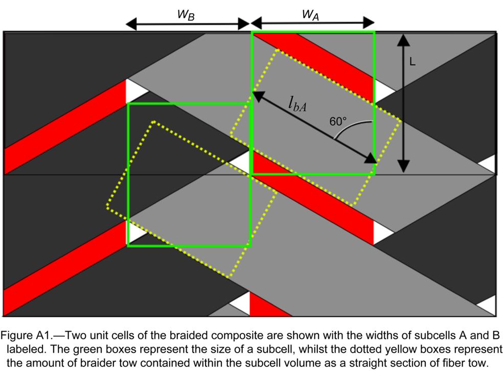
21 Appendix Straight Line Braided Composite Model The straight line model (Ref. 29) for determining the necessary UD ply thicknesses and computing the volume of fibers in the axial and braider directions contained in the subcells is presented here. The subcell widths W A and W B are measured as shown in Figure A1. Figure A1 also shows the amounts of +60 braider tow (dashed yellow box) approximated to exist inside of the subcell dimensions highlighted by the green box. Equations (4) to (6) are used to compute the volume of fiber contained in subcells A or B (the quantity of fibers in C and D will be identically equivalent). The subscripts a and b designate axial or braider tow and A and B subscripts designate the corresponding subcell. Superscript f represents volume of fibers whereas the subscript f represents volume fraction. The tow subscript represents the fiber tow, m the matrix layer, L the length of the subcell shown in Figure A1, and h the height of the subcell through the thickness as shown in Figure A2. 2 V f aa 2 d a nal (4) 4 2 f d b d b W V A ba nb lba nb (5) 2 2 sin sin f d d W V b n l h b n B bb b bb b h (6) V f V kl for k a, b; l A B (7) V WhL' kl, f, tow Vm, l 1 Vkl (8) Equations (7) and (8) compute the UD ply thicknesses for the pure matrix model. In both subcell models, the volume fractions of the three different UD plies (axial tow in A, braider tows in A, and braider tows in B) are computed according to Equations (9) to (11). The thickness of the axial UD in subcell A is assumed to be equivalent to the original pure matrix model; however, the braider UD plies in both A and B are modified according to Equations (12) and (13). k V V (9) V f, aa f,tow f VbA f, ba (10) 1 VaA V V bb f, bb (11) W hl B f 0.5 V V * ba * bb V V ba bb V V ma mb (12) (13) NASA/TM
22 NASA/TM
23 References 1. Roberts, G.D., Goldberg, R.K., Binienda, W.K., Arnold, W.A., Littell, J.D., and Kohlman, L.W., Characterization of triaxial braided composite material properties for impact simulation, American Helicopter Society (NASA/TM ), Grapevine, TX, 2009, pp Kohlman, L.W., Evaluation of Test Methods for Triaxial Braid Composites and the Development of a Large Multiaxial Test Frame for Validation Using Braided Tube Specimens, Dissertation, University of Akron, Hallquist, J.O., LS-DYNA Theory Manual, Ishikawa, T., and Chou, T.-W., Stiffness and strength behaviour of woven fabric composites, Journal of Materials Science, vol. 17, 1982, pp Ishikawa, T., and Chou, T.-W., One-Dimensional Micromechanical Analysis of Woven Fabric Composites, AIAA Journal, vol. 21, 1983, pp Naik, R.A., Failure analysis of woven and braided fabric reinforced composites, Journal of Composite Materials, vol. 29, 1995, pp Naik, N.K., and Shembekar, P.S., Elastic Behavior of woven fabric composites, Journal of Composite Materials, vol. 26, 1992, pp Yang, J.M., Ma, C.L., and Chou, T.W., Fiber inclination model of three-dimensional textile structural composites, Journal of Composite Materials, vol. 20, 1986, pp Branch, K., Shivakumar, K., and Awa, V.S., Three-dimensional tow inclination model for calculating elastic constants of three-dimensional triaxial braided composites, AIAA/ASME/ ASCE/AHS/ASC Structures, Structural Dynamics and Materials Conference, Salt Lake City, UT; United States: 1996, pp Redman, C.J., and Douglas, C.D., Theoretical prediction of the tensile elastic properties of braided composites, 38th International SAMPE Symposium, 1993, pp Ivanov, I., and Tabiei, A., Three-dimensional computational micro-mechanical model for woven fabric composites, Composite Structures, vol. 54, 2001, pp Ivanov, I., and Tabiei, A., Three-dimensional computational micro-mechanical model for woven fabric composites, Composite Structures, vol. 54, 2001, pp Ivanov, D.S., Baudry, F., Van Den Broucke, B., Lomov, S.V., Xie, H., and Verpoest, I., Failure analysis of triaxial braided composite, Composites Science and Technology, vol. 69, Jul. 2009, pp Huang, Z., The mechanical properties of composites reinforced with woven and braided fabrics, Composites Science and Technology, vol. 60, 2000, pp Huang, Z.-M., Efficient Approach to the Structure-Property Relationship of Woven and Braided Fabric-reinforced Composites up to Failure, Journal of Reinforced Plastics and Composites, vol. 24, Aug. 2005, pp Huang, Z.-M., Fujihara, K., and Ramakrishna, S., Tensile stiffness and strength of regular braid composites: Correlation of theory with experiments, Journal of Composites Technology and Research, vol. 25, 2003, pp Quek, S.C., Waas, A.M., Shahwan, K.W., and Agaram, V., Analysis of 2D triaxial flat braided textile composites, International Journal of Mechanical Sciences, vol. 45, 2003, pp Carey, J., Munro, M., and Fahim, A., Longitudinal elastic modulus prediction of a 2-D braided fiber composite, Journal of Reinforced Plastics and Composites, vol. 22, 2003, pp Masters, J.E., Foye, R.L., Pastore, C.M., and Gowayed, Y.A., Mechanical properties of triaxially braided composites: Experimental and analytical results, Journal of Composites Technology and Research, vol. 15, 1993, pp Falzon, P.J., and Herszberg, I., Mechanical performance of 2-D braided carbon/epoxy composites, Composites Science and Technology, vol. 58, 1998, pp NASA/TM
24 21. Quek, S.C., Waas, A.M., Shahwan, K.W., and Agaram, V., Failure mechanics of triaxially braided carbon composites under combined bending-compression loading, Composites Science and Technology, vol. 66, 2006, pp Quek, S.C., Waas, A., Shahwan, K.W., and Agaram, V., Compressive response and failure of braided textile composites: Part 2 computations, International Journal of Non-Linear Mechanics, vol. 39, Jun. 2004, pp Song, S., Waas, A.M., Shahwan, K.W., Xiao, X., and Faruque, O., Braided textile composites under compressive loads: Modeling the response, strength and degradation, Composites Science and Technology, vol. 67, 2007, pp Fang, G., and Liang, J., A review of numerical modeling of three-dimensional braided textile composites, Journal of Composite Materials, vol. 45, Jul. 2011, pp Yuan, Z., and Fish, J., Toward realization of computational homogenization in practice, International Journal for Numerical Methods in Engineering, vol. 73, Jan. 2008, pp Li, X., Binienda, W.K., and Littell, J.D., Methodology for Impact Modeling of Triaxial Braided Composites Using Shell Elements, Journal of Aerospace Engineering, vol. 22, Jun. 2009, pp Blinzler, B.J., Systematic Approach to Simulating Impact for Triaxially Braided Composites, Dissertation, University of Akron, Cheng, J., and Binienda, W., Simplified Braiding through Integration Points Model for Triaxially Braided Composites, Journal of Aerospace Engineering, vol. 21, 2008, pp Xiao, X., Kia, H. G., and Gong, X.-J., Strength prediction of a triaxially braided composite, Composites Part A: Applied Science and Manufacturing, vol. 42, Aug. 2011, pp Littell, J., The Experimental and Analytical Characterization of the Macromechanical Response for Triaxial Braided Composite Materials, Dissertation, University of Akron, Matzenmiller, A., Lubliner, J., and Taylor, R.L., A constitutive model for anisotropic damage in fiber-composites, Mechanics of Materials, vol. 20, 1995, pp Bednarcyk, B.A., Modeling woven polymer matrix composites with MAC/GMC, NASA/CR , Goldberg, R.K., Blinzler, B.J., and Binienda, W.K., Investigation of a macromechanical approach to analyzing triaxially braided polymer composites, AIAA J., vol. 49, no. 1, 2011, pp Littell, J., Binienda, W., Roberts, G., and Goldberg, R., Characterization of Damage in Triaxial Braided Composites under Tensile Loading, Journal of Aerospace Engineering, vol. 22, 2009, pp Charoenphan, S., Bank, L.C., and Plesha, M.E., Use of LS-DYNA shell elements in the analysis of composite plates with unabalanced and unsymmetric layups, International LS-DYNA Conference, 2000, pp NASA/TM
Computational Modeling of Adiabatic Heating in Triaxially Braided Polymer Matrix Composites Subjected to Impact Loading via a Subcell Based Approach
 Computational Modeling of Adiabatic Heating in Triaxially Braided Polymer Matrix Composites Subjected to Impact Loading via a Subcell Based Approach Christopher Sorini 1, Aditi Chattopadhyay 1, and Robert
Prediction of Elastic Constants on 3D Four-directional Braided
 Prediction of Elastic Constants on 3D Four-directional Braided Composites Prediction of Elastic Constants on 3D Four-directional Braided Composites Liang Dao Zhou 1,2,* and Zhuo Zhuang 1 1 School of Aerospace,
Nonlinearities in mechanical behavior of textile composites
 Composite Structures 71 (25) 61 67 www.elsevier.com/locate/compstruct Nonlinearities in mechanical behavior of textile composites Enrico DÕAmato Energetics Departement, L Aquila University, 674 Monteluco
Overview of Probabilistic Modeling of Woven Ceramic Matrix Composites ABSTRACT
 ABSTRACT An overview of current research efforts in understanding the cause of variability in the thermo-mechanical properties of woven ceramic matrix composites is presented. Statistical data describing
Non-conventional Glass fiber NCF composites with thermoset and thermoplastic matrices. F Talence, France Le Cheylard, France
 20 th International Conference on Composite Materials Copenhagen, 19-24th July 2015 Non-conventional Glass fiber NCF composites with thermoset and thermoplastic matrices. Thierry Lorriot 1, Jalal El Yagoubi
MODELING OF THE BEHAVIOR OF WOVEN LAMINATED COMPOSITES UNTIL RUPTURE
 MODELING OF THE BEHAVIOR OF WOVEN LAMINATED COMPOSITES UNTIL RUPTURE Jean Paul Charles, Christian Hochard,3, Pierre Antoine Aubourg,3 Eurocopter, 375 Marignane cedex, France Unimeca, 6 rue J. Curie, 3453
Micromechanics Based Multiscale Modeling. of the Inelastic Response and Failure of. Complex Architecture Composites. Kuang Liu
 Micromechanics Based Multiscale Modeling of the Inelastic Response and Failure of Complex Architecture Composites by Kuang Liu A Dissertation Presented in Partial Fulfillment of the Requirements for the
Effect of Thermal Stresses on the Failure Criteria of Fiber Composites
 Effect of Thermal Stresses on the Failure Criteria of Fiber Composites Martin Leong * Institute of Mechanical Engineering Aalborg University, Aalborg, Denmark Bhavani V. Sankar Department of Mechanical
QUESTION BANK Composite Materials
 QUESTION BANK Composite Materials 1. Define composite material. 2. What is the need for composite material? 3. Mention important characterits of composite material 4. Give examples for fiber material 5.
Crashworthiness of composite structures: Experiment and Simulation
 Crashworthiness of composite structures: Experiment and Simulation Francesco Deleo, Bonnie Wade and Prof. Paolo Feraboli (UW) Dr. Mostafa Rassaian (Boeing R&T) JAMS 2010 The Joint Advanced Materials and
MESH MODELING OF ANGLE-PLY LAMINATED COMPOSITE PLATES FOR DNS AND IPSAP
 16 TH INTERNATIONAL CONFERENCE ON COMPOSITE MATERIALS MESH MODELING OF ANGLE-PLY LAMINATED COMPOSITE PLATES FOR DNS AND IPSAP Wanil Byun*, Seung Jo Kim*, Joris Wismans** *Seoul National University, Republic
Crashworthiness of Composite Structures with Various Fiber Architectures
 11 th International L-DYNA Users Conference Crash afety Crashworthiness of Composite tructures with Various Fiber Architectures Nageswara R. Janapala 1, Fu-Kuo Chang, Robert K. Goldberg 3, Gary D. Roberts
KINK BAND FORMATION OF FIBER REINFORCED POLYMER (FRP)
") KINK BAND FORMATION OF FIBER REINFORCED POLYMER (FRP) 1 University of Science & Technology Beijing, China, niukm@ustb.edu.cn 2 Tsinghua University, Department of Engineering Mechanics, Beijing, China,
KINK BAND FORMATION OF FIBER REINFORCED POLYMER (FRP) 1 University of Science & Technology Beijing, China, niukm@ustb.edu.cn 2 Tsinghua University, Department of Engineering Mechanics, Beijing, China,
Computational Analysis for Composites
 Computational Analysis for Composites Professor Johann Sienz and Dr. Tony Murmu Swansea University July, 011 The topics covered include: OUTLINE Overview of composites and their applications Micromechanics
ANALYSIS OF LOAD FLOW AND STRESS CONCENTRATIONS IN TEXTILE COMPOSITES
 16 TH INTERNATIONAL CONFERENCE ON COMPOSITE MATERIALS ANALYSIS OF LOAD FLOW AND STRESS CONCENTRATIONS IN TEXTILE COMPOSITES Deepak Goyal*, John D. Whitcomb*, Julian Varghese* *Department of Aerospace Engineering,
ADVANCED MESOMECHANICAL MODELING OF TRIAXIALLY BRAIDED COMPOSITES FOR DYNAMIC IMPACT ANALYSIS WITH FAILURE. A Dissertation.
 ADVANCED MESOMECHANICAL MODELING OF TRIAXIALLY BRAIDED COMPOSITES FOR DYNAMIC IMPACT ANALYSIS WITH FAILURE A Dissertation Presented to The Graduate Faculty of The University of Akron In Partial Fulfillment
MATERIAL MODELING OF STRAIN RATE DEPENDENT POLYMER AND 2D TRI-AXIALLY BRAIDED COMPOSITES. A Dissertation. Presented to
 MATERIAL MODELING OF STRAIN RATE DEPENDENT POLYMER AND 2D TRI-AXIALLY BRAIDED COMPOSITES A Dissertation Presented to The Graduate Faculty of The University of Akron In Partial Fulfillment of the Requirements
Open-hole compressive strength prediction of CFRP composite laminates
 Open-hole compressive strength prediction of CFRP composite laminates O. İnal 1, A. Ataş 2,* 1 Department of Mechanical Engineering, Balikesir University, Balikesir, 10145, Turkey, inal@balikesir.edu.tr
A Numerical Study on Prediction of BFS in Composite Structures under Ballistic Impact
 VOL. 1, 2015 ISSN 2394 3750 EISSN 2394 3769 SCIENCE & TECHNOLOGY A Numerical Study on Prediction of BFS in Composite Structures under Ballistic Impact Bandaru Aswani Kumar 1, Suhail Ahmad 2 1. Research
Micro-meso draping modelling of non-crimp fabrics
 Micro-meso draping modelling of non-crimp fabrics Oleksandr Vorobiov 1, Dr. Th. Bischoff 1, Dr. A. Tulke 1 1 FTA Forschungsgesellschaft für Textiltechnik mbh 1 Introduction Non-crimp fabrics (NCFs) are
TABLE OF CONTENTS. Mechanics of Composite Materials, Second Edition Autar K Kaw University of South Florida, Tampa, USA
 Mechanics of Composite Materials, Second Edition Autar K Kaw University of South Florida, Tampa, USA TABLE OF CONTENTS 1. INTRODUCTION TO COMPOSITE MATERIALS 1.1 Introduction... 1.2 Classification... 1.2.1
Crash and Impact Simulation of Composite Structures by Using CAE Process Chain
 Crash and Impact Simulation of Composite Structures by Using CAE Process Chain Madhukar Chatiri 1, Thorsten Schütz 2, Anton Matzenmiller 3, Ulrich Stelzmann 1 1 CADFEM GmbH, Grafing/Munich, Germany, mchatiri@cadfem.de
DESIGN OF LAMINATES FOR IN-PLANE LOADING
 DESIGN OF LAMINATES FOR IN-PLANOADING G. VERCHERY ISMANS 44 avenue F.A. Bartholdi, 72000 Le Mans, France Georges.Verchery@m4x.org SUMMARY This work relates to the design of laminated structures primarily
A Stress Gradient Failure Theory for Textile Structural Composites. Final Technical Report submitted to ARO
 A Stress Gradient Failure Theory for Textile Structural Composites Final Technical Report submitted to ARO By RYAN KARKKAINEN and BHAVANI SANKAR University of Florida Department of Mechanical & Aerospace
LAMINATION THEORY FOR THE STRENGTH OF FIBER COMPOSITE MATERIALS
 XXII. LAMINATION THEORY FOR THE STRENGTH OF FIBER COMPOSITE MATERIALS Introduction The lamination theory for the elastic stiffness of fiber composite materials is the backbone of the entire field, it holds
Calibration and Experimental Validation of LS-DYNA Composite Material Models by Multi Objective Optimization Techniques
 9 th International LS-DYNA Users Conference Optimization Calibration and Experimental Validation of LS-DYNA Composite Material Models by Multi Objective Optimization Techniques Stefano Magistrali*, Marco
Multi Disciplinary Delamination Studies In Frp Composites Using 3d Finite Element Analysis Mohan Rentala
 Multi Disciplinary Delamination Studies In Frp Composites Using 3d Finite Element Analysis Mohan Rentala Abstract: FRP laminated composites have been extensively used in Aerospace and allied industries
Comparison of Ply-wise Stress-Strain results for graphite/epoxy laminated plate subjected to in-plane normal loads using CLT and ANSYS ACP PrepPost
 Comparison of Ply-wise Stress-Strain results for graphite/epoxy laminated plate subjected to in-plane normal loads using CLT and ANSYS ACP PrepPost 1 Mihir A. Mehta, 2 Satyen D. Ramani 1 PG Student, Department
Module III - Macro-mechanics of Lamina. Lecture 23. Macro-Mechanics of Lamina
 Module III - Macro-mechanics of Lamina Lecture 23 Macro-Mechanics of Lamina For better understanding of the macromechanics of lamina, the knowledge of the material properties in essential. Therefore, the
Modeling Hailstone Impact onto Composite Material Panel Under a Multi-axial State of Stress
 Modeling Hailstone Impact onto Composite Material Panel Under a Multi-axial State of Stress Authors Marco ANGHILERI * Luigi-M L CASTELLETTI * Andrea MILANESE * and Andrea SEMBOLONI * Affiliation * Politecnico
Influence of the filament winding process variables on the mechanical behavior of a composite pressure vessel
 Influence of the filament winding process variables on the mechanical behavior of a composite pressure vessel G. Vargas 1 & A. Miravete 2 1 Universidad Pontificia Bolivariana, Facultad de Ingeniería Mecánica,
Enhancing Prediction Accuracy In Sift Theory
 18 TH INTERNATIONAL CONFERENCE ON COMPOSITE MATERIALS Enhancing Prediction Accuracy In Sift Theory J. Wang 1 *, W. K. Chiu 1 Defence Science and Technology Organisation, Fishermans Bend, Australia, Department
In-situ local strain measurement in textile composites with embedded optical fibre sensors
 In-situ local strain measurement in textile composites with embedded optical fibre sensors S. Daggumati, E. Voet, I. De Baere, W. Van Paepegem & J. Degrieck Ghent University, Department of Materials Science
Elastic parameters prediction under dynamic loading based on the. unit cell of composites considering end constraint effect
 Elastic parameters prediction under dynamic loading based on the unit cell of composites considering end constraint effect Wang Meng 1,, Fei Qingguo 1,, Zhang Peiwei 1, (1. Institute of Aerospace Machinery
Composite Damage Material Modeling for Crash Simulation: MAT54 & the Efforts of the CMH-17 Numerical Round Robin
 Composite Damage Material Modeling for Crash Simulation: MAT54 & the Efforts of the CMH-17 Numerical Round Robin 2014 Technical Review Bonnie Wade (UW) Prof. Paolo Feraboli AMTAS (JAMS) Crashworthiness
Size Effects In the Crushing of Honeycomb Structures
 45th AIAA/ASME/ASCE/AHS/ASC Structures, Structural Dynamics & Materials Conference 19-22 April 2004, Palm Springs, California AIAA 2004-1640 Size Effects In the Crushing of Honeycomb Structures Erik C.
Strength of GRP-laminates with multiple fragment damages
 Strength of GRP-laminates with multiple fragment damages S. Kazemahvazi, J. Kiele, D. Zenkert Kungliga Tekniska Högskolan, KTH 100 44 Stockholm, Sweden sohrabk@kth.se SUMMARY The strength of glass fibre
Composite models 30 and 131: Ply types 0 and 8 calibration
 Model calibration Composite Bi-Phase models 30 and 3 for elastic, damage and failure PAM-CRASH material model 30 is for solid and 3 for multi-layered shell elements. Within these models different ply types
MECHANICAL FAILURE OF A COMPOSITE HELICOPTER STRUCTURE UNDER STATIC LOADING
 MECHANICAL FAILURE OF A COMPOSITE HELICOPTER STRUCTURE UNDER STATIC LOADING Steven Roy, Larry Lessard Dept. of Mechanical Engineering, McGill University, Montreal, Québec, Canada ABSTRACT The design and
Impact and Crash Modeling of Composite Structures: A Challenge for Damage Mechanics
 Impact and Crash Modeling of Composite Structures: A Challenge for Damage Mechanics Dr. A. Johnson DLR Dr. A. K. Pickett ESI GmbH EURO-PAM 99 Impact and Crash Modelling of Composite Structures: A Challenge
Multiscale Approach to Damage Analysis of Laminated Composite Structures
 Multiscale Approach to Damage Analysis of Laminated Composite Structures D. Ivančević and I. Smojver Department of Aeronautical Engineering, Faculty of Mechanical Engineering and Naval Architecture, University
THE MUTUAL EFFECTS OF SHEAR AND TRANSVERSE DAMAGE IN POLYMERIC COMPOSITES
 THE 19 TH INTERNATIONAL CONFERENCE ON COMPOSITE MATERIALS THE MUTUAL EFFECTS OF SHEAR AND TRANSVERSE DAMAGE IN POLYMERIC COMPOSITES L.V. Smith 1 *, M. Salavatian 1 1 School of Mechanical and Materials
PRELIMINARY PREDICTION OF SPECIMEN PROPERTIES CLT and 1 st order FEM analyses
 OPTIMAT BLADES Page 1 of 24 PRELIMINARY PREDICTION OF SPECIMEN PROPERTIES CLT and 1 st order FEM analyses first issue Peter Joosse CHANGE RECORD Issue/revision date pages Summary of changes draft 24-10-02
Module-6: Laminated Composites-II. Learning Unit-1: M6.1. M 6.1 Structural Mechanics of Laminates
 Module-6: Laminated Composites-II Learning Unit-1: M6.1 M 6.1 Structural Mechanics of Laminates Classical Lamination Theory: Laminate Stiffness Matrix To this point in the development of classical lamination
A FINITE ELEMENT MODEL TO PREDICT MULTI- AXIAL STRESS-STRAIN RESPONSE OF CERAMIC MATRIX COMPOSITES WITH STRAIN INDUCED DAMAGE
 A FINITE ELEMENT MODEL TO PREDICT MULTI- AXIAL STRESS-STRAIN RESPONSE OF CERAMIC MATRIX COMPOSITES WITH STRAIN INDUCED DAMAGE Daxu Zhang and D. R. Hayhurst School of Mechanical, Aerospace and Civil Engineering,
LS-DYNA MAT54 for simulating composite crash energy absorption
 LS-DYNA MAT54 for simulating composite crash energy absorption Bonnie Wade and Paolo Feraboli (UW) Mostafa Rassaian (Boeing BR&T) JAMS 2011 The Joint Advanced Materials and Structures Center of Excellence
DRAPING SIMULATION. Recent achievements and future trends. Dr. Sylvain Bel LGCIE University Lyon 1
 DRAPING SIMULATION Recent achievements and future trends 1 Dr. Sylvain Bel LGCIE University Lyon 1 2 DRAPING SIMULATION Why? How? What? DRAPING SIMULATION WHY? Clamps Punch Fabric Die 1 2 Resin 3 4 Fig.
NUMERICAL SIMULATION OF DAMAGE IN THERMOPLASTIC COMPOSITE MATERIALS
 5 th European LS-DYNA Users Conference Composites NUMERICAL SIMULATION OF DAMAGE IN THERMOPLASTIC COMPOSITE MATERIALS Kevin Brown 1, Richard Brooks, Nicholas Warrior School of Mechanical, Materials and
An integrated approach to the design of high performance carbon fibre reinforced risers - from micro to macro - scale
 An integrated approach to the design of high performance carbon fibre reinforced risers - from micro to macro - scale Angelos Mintzas 1, Steve Hatton 1, Sarinova Simandjuntak 2, Andrew Little 2, Zhongyi
A copy can be downloaded for personal non-commercial research or study, without prior permission or charge
 York, C. B. (2015) Influence of bending twisting coupling on compression and shear buckling strength. Stability of Structures 14th Symposium, Zakopane, Poland, 8-12 Jun 2015. Copyright 2015 The Author.
COMPARISON OF EXPERIMENTAL RESULTS WITH FEM ONES OF RECTANGULAR CFRP TUBES FOR FRONT SIDE MEMBERS OF AUTOMOBILES
 16 TH INTERNATIONAL CONFERENCE ON COMPOSITE MATERIALS COMPARISON OF EXPERIMENTAL RESULTS WITH FEM ONES OF RECTANGULAR CFRP TUBES FOR FRONT SIDE MEMBERS OF AUTOMOBILES Hyoung-Soo Kim*, Goichi Ben**,Yoshio
Crashworthy Design of Composite Structures Using CAE Process Chain
 0 th European LS-DYNA Conference 205, Würzburg, Germany Crashworthy Design of Composite Structures Using CAE Process Chain Madhukar Chatiri, Thorsten Schuetz 2, Anton Matzenmiller 3 CADFEM GmbH, Grafing
ISSN Volume 1 Issue 4 May 2012 FEA Information Engineering Journal
 ISSN 2167-1273 Volume 1 Issue 4 May 2012 FEA Information Engineering Journal Honeywell engine Aerospace Journal FEA Information Engineering Journal Aim and Scope FEA Information Engineering Journal (FEAIEJ
EVALUATION OF DAMAGE DEVELOPMENT FOR NCF COMPOSITES WITH A CIRCULAR HOLE BASED ON MULTI-SCALE ANALYSIS
 THE 19 TH INTERNATIONAL CONFERENCE ON COMPOSITE MATERIALS EVALUATION OF DAMAGE DEVELOPMENT FOR NCF COMPOSITES WITH A CIRCULAR HOLE BASED ON MULTI-SCALE ANALYSIS T. Kurashiki 1 *, Y. Matsushima 1, Y. Nakayasu
PREDICTING THE CONSTITUTIVE BEHAVIOR OF BIAXIAL BRAIDED COMPOSITES USING BEAM UNIT CELLS
 THE 19TH INTERNATIONAL CONFERENCE ON COMPOSITE MATERIALS PREDICTING THE CONSTITUTIVE BEHAVIOR OF BIAXIAL 1 J. Cichosz1*, J. Bückle1, R. Hinterhölzl1, M. Wolfahrt2 Institute for Carbon Composites, Technische
IJSER 1. INTRODUCTION. M.Elhadary
 1591 A new failure criterion for GRP composite materials subjected to in-phase and out-of-phase biaxial fatigue loading under different stress ratios M.Elhadary Abstract this studying the fatigue behavior
NUMERICAL FEM ANALYSIS FOR THE PART OF COMPOSITE HELICOPTER ROTOR BLADE
 Journal of KONES Powertrain and Transport, Vol. 19, No. 1 2012 NUMERICAL FEM ANALYSIS FOR THE PART OF COMPOSITE HELICOPTER ROTOR BLADE Hubert D bski Lublin University of Technology, Department of Machine
An orthotropic damage model for crash simulation of composites
 High Performance Structures and Materials III 511 An orthotropic damage model for crash simulation of composites W. Wang 1, F. H. M. Swartjes 1 & M. D. Gan 1 BU Automotive Centre of Lightweight Structures
Tensile behaviour of anti-symmetric CFRP composite
 Available online at www.sciencedirect.com Procedia Engineering 1 (211) 1865 187 ICM11 Tensile behaviour of anti-symmetric CFRP composite K. J. Wong a,b, *, X. J. Gong a, S. Aivazzadeh a, M. N. Tamin b
SOME RESEARCH ON FINITE ELEMENT ANALYSIS OF COMPOSITE MATERIALS
 Mechanical Testing and Diagnosis ISSN 2247 9635, 2012 (II), Volume 3, 79-85 SOME RESEARCH ON FINITE ELEMENT ANALYSIS OF COMPOSITE MATERIALS Valeriu DULGHERU, Viorel BOSTAN, Marin GUŢU Technical University
MODELLING OF THE THERMO-MECHANICAL PROPERTIES OF WOVEN COMPOSITES DURING THE CURE
 TH 9 TH INTRNATIONAL ONFRN ON OMPOSIT MATRIALS MODLLING OF TH THRMO-MHANIAL PROPRTIS OF WOVN OMPOSITS DURING TH UR L. Khoun,, K.S. hallagulla,, P. Hubert Department of Mechanical ngineering, McGill University,
INVESTIGATION OF THE PROCESSING PARAMETERS OF A 3D WOVEN REINFORCEMENT
 INVESTIGATION OF THE PROCESSING PARAMETERS OF A 3D WOVEN REINFORCEMENT Andreas Endruweit, Dhiren K. Modi and Andrew C. Long School of Mechanical, Materials and Manufacturing Engineering, University of
Modelling the nonlinear shear stress-strain response of glass fibrereinforced composites. Part II: Model development and finite element simulations
 Modelling the nonlinear shear stress-strain response of glass fibrereinforced composites. Part II: Model development and finite element simulations W. Van Paepegem *, I. De Baere and J. Degrieck Ghent
Benefits of Force Limiting Vibration Testing
 NASA/TM 1999-209382 Benefits of Force Limiting Vibration Testing Mark E. McNelis Glenn Research Center, Cleveland, Ohio Terry D. Scharton Jet Propulsion Laboratory, Pasadena, California August 1999 The
Applicability of the Continuum-shell Theories to the Mechanics of Carbon Nanotubes
 NASA/CR-2002-211460 ICASE Report No. 2002-7 Applicability of the Continuum-shell Theories to the Mechanics of Carbon Nanotubes V.M. Harik ICASE, Hampton, Virginia T.S. Gates and M.P. Nemeth NASA Langley
Non-Linear Finite Element Modeling of THUNDER Piezoelectric Actuators
 NASA/TM-1999-209322 ARL-TR-1977 Non-Linear Finite Element Modeling of THUNDER Piezoelectric Actuators Barmac K. Taleghani U. S. Army Research Laboratory Vehicle Technology Directorate Langley Research
Effect of Fiber Waviness on the Compressive Strength of Unidirectional Carbon Fiber Composites
 53rd AIAA/ASME/ASCE/AHS/ASC Structures, Structural Dynamics and Materials Conference20th AI 23-26 April 2012, Honolulu, Hawaii AIAA 2012-1422 Effect of Fiber Waviness on the Compressive Strength of
ANALYTICAL AND EXPERIMENTAL ELASTIC BEHAVIOR OF TWILL WOVEN LAMINATE
 ANALYTICAL AND EXPERIMENTAL ELASTIC BEHAVIOR OF TWILL WOVEN LAMINATE Pramod Chaphalkar and Ajit D. Kelkar Center for Composite Materials Research, Department of Mechanical Engineering North Carolina A
PLY LEVEL UNCERTAINTY EFFECTS ON FAILURE OF COMPOSITE
 7th European Workshop on Structural Health Monitoring July 8-11, 2014. La Cité, Nantes, France More Info at Open Access Database www.ndt.net/?id=17206 PLY LEVEL UNCERTAINTY EFFECTS ON FAILURE OF COMPOSITE
An overview of Carbon Fiber modeling in LS-DYNA. John Zhao October 23 th 2017
 An overview of Carbon Fiber modeling in LS-DYNA John Zhao zhao@lstc.com October 23 th 2017 Outline Manufacturing of Carbon Fiber Compression molding *MAT_277 & 278 *MAT_293 *MAT_249 Resin transform molding
MESO-SCALE MODELLING IN THERMOPLASTIC 5-HARNESS SATIN WEAVE COMPOSITE
 MESO-SCALE MODELLING IN THERMOPLASTIC 5-HARNESS SATIN WEAVE COMPOSITE S. Daggumati a*,i. De Baere a, W. Van Paepegem a, J. Degrieck a, J. Xu b, S.V. Lomov b, I. Verpoest b a Ghent University, Dept. of
INITIATION AND PROPAGATION OF FIBER FAILURE IN COMPOSITE LAMINATES
 THE 19 TH INTERNATIONAL CONFERENCE ON COMPOSITE MATERIALS INITIATION AND PROPAGATION OF FIBER FAILURE IN COMPOSITE LAMINATES E. Iarve 1,2*, D. Mollenhauer 1, T. Breitzman 1, K. Hoos 2, M. Swindeman 2 1
NUMERICAL DESIGN OF COMPOSITE MATERIALS THROUGH MULTI-SCALE COMPUTER SIMULATION
 THE 19 TH INTERNATIONAL CONFERENCE ON COMPOSITE MATERIALS NUMERICAL DESIGN OF COMPOSITE MATERIALS THROUGH J. Leach 1 *, J. Mackiewicz 2, Dr. S. Risser 1 1 Battelle Memorial Institute, Columbus, OH, USA,
INTERNATIONAL JOURNAL OF APPLIED ENGINEERING RESEARCH, DINDIGUL Volume 2, No 1, 2011
 Interlaminar failure analysis of FRP cross ply laminate with elliptical cutout Venkateswara Rao.S 1, Sd. Abdul Kalam 1, Srilakshmi.S 1, Bala Krishna Murthy.V 2 1 Mechanical Engineering Department, P. V.
SIZE EFFECTS IN THE COMPRESSIVE CRUSHING OF HONEYCOMBS
 43rd AIAA/ASME/ASCE/AHS/ASC Structures, Structural Dynamics, and Materials Con 22-25 April 2002, Denver, Colorado SIZE EFFECTS IN THE COMPRESSIVE CRUSHING OF HONEYCOMBS Erik C. Mellquistand Anthony M.
Progressive Failure Analysis Methodology for Laminated Composite Structures
 NASA/TP-999-0907 Progressive Failure Analysis Methodology for Laminated Composite Structures David W. Sleight Langley Research Center, Hampton, Virginia March 999 The NASA STI Program Office... in Profile
The Accuracy of Characteristic Length Method on Failure Load Prediction of Composite Pinned Joints
 , June 30 - July 2, 2010, London, U.K. The Accuracy of Characteristic Length Method on Failure Load Prediction of Composite Pinned Joints O. Aluko, and Q. Mazumder Abstract An analytical model was developed
Predicting Failure of Multiangle Composite Laminates
 Predicting Failure of Multiangle Composite Laminates Preliminary discussion (not in textbook): Micromechanics failure analyses vs Macromechanics failure analyses Fiber Architecture of Some Common Composite
Hygrothermal stresses in laminates
 Hygrothermal stresses in laminates Changing environment conditions (temperature and moisture) have an important effect on the properties which are matrix dominated. Change in temperaturet and moisture
FINITE ELEMENT AND EXPERIMENTAL STUDY OF NOVEL CONCEPT OF 3D FIBRE CELL STRUCTURE
 FINITE ELEMENT AND EXPERIMENTAL STUDY OF NOVEL CONCEPT OF 3D FIBRE CELL STRUCTURE M. Růžička, V. Kulíšek 2, J. Had, O. Prejzek Department of Mechanics, Biomechanics and Mechatronics, Faculty of Mechanical
A RESEARCH ON NONLINEAR STABILITY AND FAILURE OF THIN- WALLED COMPOSITE COLUMNS WITH OPEN CROSS-SECTION
 A RESEARCH ON NONLINEAR STABILITY AND FAILURE OF THIN- WALLED COMPOSITE COLUMNS WITH OPEN CROSS-SECTION H. Debski a*, J. Bienias b, P. Jakubczak b a Faculty of Mechanical Engineering, Department of Machine
MICROMECHANICAL ANALYSIS OF FRP COMPOSITES SUBJECTED TO LONGITUDINAL LOADING
 MICROMECHANICAL ANALYSIS OF FRP COMPOSITES SUBJECTED TO LONGITUDINAL LOADING N. Krishna Vihari 1, P. Phani Prasanthi 1, V. Bala Krishna Murthy 2* and A. Srihari Prasad 3 1 Mech. Engg. Dept., P. V. P. Siddhartha
Overview of Hygrothermally Stable Laminates with Improved Extension-twist Coupling
 Overview of Hygrothermally Stable Laminates with Improved Extension-twist Coupling R. Haynes epartment of erospace Engineering, Georgia Institute of Technology 27 Ferst rive W, tlanta, G 3332-5, US robert.haynes@gatech.edu
Development of GENOA Progressive Failure Parallel Processing Software Systems
 NASA/CR 1999-209404 Development of GENOA Progressive Failure Parallel Processing Software Systems Frank Abdi Alpha STAR Corporation, Long Beach, California Levon Minnetyan Clarkson University, Potsdam,
CHEM-E2200: Polymer blends and composites Fibre architecture and principles of reinforcement
 CHEM-E2200: Polymer blends and composites Fibre architecture and principles of reinforcement Mark Hughes 19 th September 2016 Outline Fibre architecture Volume fraction and the rule of mixtures Principle
A STRUCTURE DESIGN OF CFRP REAR PRESSURE BULKHEAD WITHOUT STIFFENERS
 Xi an, 2-25 th August 217 A STRUCTURE DESIGN OF CFRP REAR PRESSURE BULKHEAD WITHOUT STIFFENERS LI Zhongyang 1, LI Dong 2 Mailbox72-35, Yanliang District, Xian, China, Email: zhongyangli@live.com Keywords:
Getting Started with Composites Modeling and Analysis
 Getting Started with Composites Modeling and Analysis IN THIS WEBINAR: PRESENTED BY: Orthotropic materials and how to define them Composite Laminate properties and modeling Composite failure theories and
Fracture Mechanics, Damage and Fatigue: Composites
 University of Liège Aerospace & Mechanical Engineering Fracture Mechanics, Damage and Fatigue: Composites Ludovic Noels Computational & Multiscale Mechanics of Materials CM3 http://www.ltas-cm3.ulg.ac.be/
THE INFLUENCE OF IN-PLANE DENSITY VARIATION ON ENGINEERING PROPERTIES OF ORIENTED STRANDBOARD: A FINITE ELEMENT SIMULATION
 Proceedings of McMat5: 5 Joint ASME/ASCE/SES Conference on Mechanics and Materials June 1-3, 5, Baton Rouge, Louisiana, USA 255 THE INFLUENCE OF IN-PLANE DENSITY VARIATION ON ENGINEERING PROPERTIES OF
MESOMECHANICAL MODEL FOR FAILURE STUDY OF TWO DIMENSIONAL TRIAXIAL BRAIDED COMPOSITE MATERIALS. A Dissertation. Presented to
 MESOMECHANICAL MODEL FOR FAILURE STUDY OF TWO DIMENSIONAL TRIAXIAL BRAIDED COMPOSITE MATERIALS A Dissertation Presented to The Graduate Faculty of The University of Akron In Partial Fulfillment of the
EXPERIMENTAL AND FINITE ELEMENT MODAL ANALYSIS OF VARIABLE STIFFNESS COMPOSITE LAMINATED PLATES
 11 th International Conference on Vibration Problems Z. Dimitrovová et al. (eds.) Lisbon, Portugal, 9-12 September 2013 EXPERIMENTAL AND FINITE ELEMENT MODAL ANALYSIS OF VARIABLE STIFFNESS COMPOSITE LAMINATED
DEVELOPMENT OF THERMOELASTIC STRESS ANALYSIS AS A NON-DESTRUCTIVE EVALUATION TOOL
 DEVELOPMENT OF THERMOELASTIC STRESS ANALYSIS AS A NON-DESTRUCTIVE EVALUATION TOOL S. Quinn*, R.K. Fruehmann and J.M. Dulieu-Barton School of Engineering Sciences University of Southampton Southampton SO17
46th AIAA/ASME/ASCE/AHS/ASC Structures, Structural Dynamics, and Materials Conference April 2005 Austin, Texas
 th AIAA/ASME/ASCE/AHS/ASC Structures, Structural Dynamics & Materials Conference - April, Austin, Texas AIAA - AIAA - Bi-stable Cylindrical Space Frames H Ye and S Pellegrino University of Cambridge, Cambridge,
ME 7502 Lecture 2 Effective Properties of Particulate and Unidirectional Composites
 ME 75 Lecture Effective Properties of Particulate and Unidirectional Composites Concepts from Elasticit Theor Statistical Homogeneit, Representative Volume Element, Composite Material Effective Stress-
PLY WAVINESS ON IN-PLANE STIFFNESS OF COMPOSITE LAMINATES
 PLY WAVINESS ON IN-PLANE STIFFNESS OF COMPOSITE LAMINATES Cimini Jr., Carlos A., and Tsai, Stephen W. 2 Department of Mechanical Engineering, Federal University of Minas Gerais Av. Antônio Carlos, 6627
Online publication date: 23 October 2010
 This article was downloaded by: [informa internal users] On: 1 November 2010 Access details: Access Details: [subscription number 755239602] Publisher Taylor & Francis Informa Ltd Registered in England
ACDC. User Manual. Ver. 1.0
 ACDC User Manual Ver. 1.0 Centre Composite December 2016 ACDC, Ver. 1.0 User Manual Centre Composite, 2016 (software@composite.lv) Table of Contents Introduction... 1 System requirements... 1 Theoretical
Transactions on Engineering Sciences vol 21, 1998 WIT Press, ISSN
 Micromechanical modelling of textile composites using variational principles A. Prodromou, Ph. Vandeurzen, G. Huysmans, J. Ivens & I. Verpoest Department ofmetallurgy and Materials Engineering, Katholieke
FINITE ELEMENT ANALYSIS OF COMPOSITE MATERIALS
 FINITE ELEMENT ANALYSIS OF COMPOSITE MATERIALS Ever J. Barbero Department of Mechanical and Aerospace Engineering West Virginia University USA CRC Press Taylor &.Francis Group Boca Raton London New York
ISSN: ISO 9001:2008 Certified International Journal of Engineering Science and Innovative Technology (IJESIT) Volume 2, Issue 4, July 2013
 Volume 2, Issue 4, July 2013") Delamination Studies in Fibre-Reinforced Polymer Composites K.Kantha Rao, Dr P. Shailesh, K. Vijay Kumar 1 Associate Professor, Narasimha Reddy Engineering College Hyderabad. 2 Professor, St. Peter s Engineering
Delamination Studies in Fibre-Reinforced Polymer Composites K.Kantha Rao, Dr P. Shailesh, K. Vijay Kumar 1 Associate Professor, Narasimha Reddy Engineering College Hyderabad. 2 Professor, St. Peter s Engineering