Modular feeding technology 2016
|
|
|
- Alexandrina Crawford
- 6 years ago
- Views:
Transcription

1 Modular feeding technology 01 Feeding Handling Transporting

2 Highest quality in handling and feeding technology high grade, reliable, innovative and always up-to-date partcommunity.com
3
4 Table of contents Linear feeder 1 Bowl feeder drives Feeding bowls Refilling units Control devices Afag-Chrome-Line feeding components Flex feeding Diagnostics and training 8 Project-specific components 9 Keyword directory 10
5 Feeding technology 01


6 Table of contents Technical description Micro-spreading technique Reactive force compensation Linear feeder HLF-M 1 HLF-P 18 PSG1 KLF 8 LF Sub-structure linear feeder Bowl feeder drives BF WV Sub-structure bowl feeder drives Feeding bowls Blank bowl BB Step helix BB-S Groove helix BB-N Radius helix BB-R Stepped bowls TS 8 Refilling units Refillable vibratoy hopper NVB 8 Vibratory hopper NVD 8 Conveyor belt hopper NBB 88 Control devices Phase angle controller IRG 98 Control device Smart Box 10 Control device SIGA 10 Afag-Chrome-Line feeding components Feeding station 110 Base plate 11 Base frame GG 11 Buffer control 11 Light barrier GL 118 Level control device 10 Collecting container 1 Bowl cover 1 Flex Feeding Aflex 18 Flipconveyor 10 Diagnostic and training Workshop and training 1 Laboratory instrument QRG 1 Handheld demagnetizer HEM 1 Feeding technology 01
7 Micro-spreading technique A vibratory feeder is a device transforming electro-magnetically produced vibrations by means of magnet, magnet armature and leaf springs into mechanical vibrations and uses them to convey loads. The targeted conveying movement of the work piece is based on the micro-spreading principle, where the form of movement of the conveying device forces the work piece into a micro spreading movement. A Work piece B Conveyor track α Angle of trajectory β Angle of inclination γ Angle of ascent The conditions of movement can be described as follows: 1 Stationary condition Propulsion Trajectory parabola Impact During propulsion, the work piece lifts off from the surface of the conveying device when the vertical normal acceleration acting on the material exceeds the acceleration due to gravity. Contact between the work piece and the conveying device is completely removed. The impact following propulsion occurs as an energetic semi-elastic shock and is the main cause of the noise emissions, which are dependent on the nature of the work piece and conveying organ. In the stationary condition, there is no relative motion between the work piece and conveying device and there is static friction between the partners. If normal acceleration exceeds the amount of the maximum static friction, the work piece moves again into the spread state of motion. Feeding technology 01
8 Reactive force compensation F 1 C 1 m m 1 F 1 C 1 m 1 m F = F1 F 1 C 1 m 1 F F = 1 C m F = F 1 F 1 C 1 C F F = F 1 C 1 m F 1 m Conventional -mass vibration system Counter vibration principle Coupled counter-vibration principle Notation F1, F Forces F1, F Reactive forces m1 Useful mass m Counter mass m Base attached to the underground c1, c Springs Reactive force compensation Afag bowl feeder WV and linear LF feeders operate on the conventional twin-mass vibration principle. The reactive force created by the vibration of the useful mass (m 1 ) is compensated by a larger foundation (counter) mass (m ). Afag bowl feeder BF and linear HLF and KLF feeders operate on the counter vibration principle with reactive force compensation. Here a useful mass (m 1 ) vibrates in precisely the opposite direction to a counter mass (m ). The useful and counter masses are attached to a base ring respectively base plate by means of leaf springs. Equal reactive forces are created, which are transmitted via the leaf springs to the base plate while maintaining the mass moment of inertia and the mass of the feeder bowl or the feeder rail when the useful and counter masses vibrate. By reason of the vibration of the useful mass and counter mass in the opposite direction the reactive forces at the base plate virtually counterbalance each other. Avoidance of vibration transmission to the underground enables attachment to the base, and a precisely defined and fixed interface between the feed and assembling facilities can be guaranteed. Feeding technology 01
9 1 1 1 Linear feeder Track Cover Side plate Trim weight Sub-structure 8 Feeding technology 01
10 Linear feeder Linear feeder Linear feeder HLF-M 1 Linear feeder HLF-P 18 Control devices PSG1 Accessory HLF Linear feeder KLF 8 Accessory KLF Linear feeder LF Accessory LF 0 Sub-structure linear feeder 1 Feeding technology 01 9

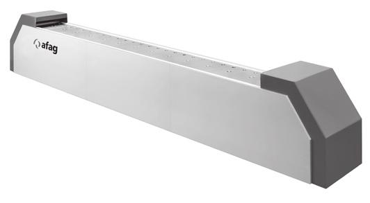
11 Linear feeder HLF The Afag hybrid Magnet or piezo 1 0 Feeding technology 01
12 HLF HLF - the new Afag generation of linear feeders stands for Hybrid Linear Feeder. Depending on application, the drive technology best suited for the project-specific requirements can be selected for this new type of linear feeder. The drive systems available include the familiar actuation based on an oscillating magnet (HLF-M) and a new patented piezoelectric drive (HLF-P). The mechanical interfaces are identical irrespective of the drive system. This allows the drive system to be changed easily. The advantages of the piezo driven linear feeder are particularly evident when feeding extremely small parts: Even more precise air gap between track transitions (< 0.1 mm) may be achieved depending on application Finer oscillation (approximating to sliding motion) Smaller tolerances / parts are conducted more closely in the track even better precision No mechanical adjustment required before operation No modifications for operation in 0/0 Hz power supply systems The conveying rate is not influenced by voltage fluctuations in the power system No environmental electromagnetic influence on the system High energy efficiency (high energy saving potential compared to magnetic technology) External mechanical interfaces are compatible with magnetic technology Reactive force compensation (as for magnetic technology) 1 The new linear feeders (both drive systems) have a compact, closed design with optimized reactive force compensation. This is based on dynamic balancing of the weight and counterweight, eliminating the majority of free oscillating forces directly in the machine. Another new feature is the long and broad mounting surface of the conveying tracks, which considerably extends track design options. Feeding technology 01 11
13 Linear feeder HLF-M Compendium Accessories HLF-M 1 Feeding technology 01
14 HLF-M For fastening the rail to the HLF two variants are possible: 1 Variant 1 Construction with side plate O Variant Construction with side plate S Feeding technology 01 1
15 E Linear feeder HLF-M HLF0--M P A X S F Z E/ Ø D1 R -Y +Y S H M E B Ø D Ø D C K G N R S = Feeding direction = Track center of gravity 1 1 Feeding technology 01
16 Technical data HLF-M Type HLF0-M HLF1-M HLF-M Order no. 0 V / 0 Hz V / 0 Hz Dimensions Units A [mm] max. 00 max. 00 max. 00 B [mm] 0 8 C [mm] D1 [mm] 9 9 D --- x M x M x M D [mm] x H x H x H E [mm] 0 F [mm] G [mm] H [mm] K [mm] M [mm] N [mm] P [mm] Centre of gravity of rail X [mm] 8 ± ± 10 1 ± 0 Y [mm] 0 ± 9 0 ± 10 0 ± 1 Z [mm] ± 8. 8 ± ± 1 Technical data Useful mass 0. ± 0.1 kg 1. ± 0.1 kg. ± 0.1 kg Weight device 1. kg.00 kg.1 kg Max. speed m/min m/min m/min Power 1 VA 19 VA 100 VA Protection class IP IP IP Reactive force compensation Vibrator frequency (electric) in Hz 0/0 0/0 0/0 Mechanical vibrations per min 000/00 000/00 000/00 Scope of delivery Device Springs = existent Note: Refer to p. 98 for appropriate control devices. Track not included in scope of supply. Feeding technology 01 1
17 Linear feeder HLF-M Compendium Mechanical connection of HLF feeders 1 To realize tracks with a large maximum length, the useful and counter masses can be mechanically connected up to HLF feeders and operated by a single control unit. 1 Feeding technology 01
18 Technical data HLF-M Notation 1 Drive Four way splitter for vibration drives Control device 1 Accessory linear feeder Four way splitter for vibration drives Order no. 00 A E C F G B D Dimensions Units A [mm] 9 B [mm] 1 C [mm] 11 D [mm] E [mm] 18 F [mm] 1 G [mm]. Feeding technology 01 1
19 Linear feeder HLF-P Compendium Accessories HLF-P 1 8 Feeding technology 01
20 HLF-P For fastening the rail to the HLF two variants are possible: 1 Variant 1 Construction with side plate O Variant Construction with side plate S Feeding technology 01 19
21 E Linear feeder HLF-P HLF0-1-P P X A +Y-Y S S F Z E/ Ø D1 R H E M Ø D Ø D B C K G N 1 R S = Feeding direction = Track center of gravity 0 Feeding technology 01
22 Technical data HLF-P Type HLF0-P HLF1-P Order no. 0 V / 11 Hz Dimensions Units A [mm] max. 0 max. 0 B [mm] 0 C [mm] D1 [mm] 9 D --- x M x M D [mm] x H x H E [mm] F [mm] 80 G [mm] H [mm] 0 9 K [mm] 0 80 M [mm] N [mm] P [mm] Centre of gravity of rail X [mm] 8 ± ± 10 Y [mm] 0 ± 9 0 ± 10 Z [mm] ± 8. 8 ± 11 Technical data Useful mass 0. ± 0.1 kg 1. ± 0.1 kg Weight device 1. kg.00 kg Max. speed m/min m/min Power VA VA Protection class IP1 IP1 Reactive force compensation Vibrator frequency (electric) in Hz 0/0 190/10 Mechanical vibrations per min 100/ /100 Scope of delivery Device = existent Note: Refer to p. for appropriate control devices. Track not included in scope of supply. Feeding technology 01 1
23 Control devices PSG1 PSG1 A D C H G B E F Feeding technology 01
![Technical data PSG1 Piezoelectic control device PSG1 Order no. 0 V / 11 Hz 0118 Dimensions Units A [mm] 9 B [mm] 0 C [mm] 1. D [mm] E [mm] 19 F [mm] 0 G [mm].](/docs-images/74/69886063/images/24-0.jpg "H [mm] 9 1 Technical data Mains frequency 0")
24 Technical data PSG1 Piezoelectic control device PSG1 Order no. 0 V / 11 Hz 0118 Dimensions Units A [mm] 9 B [mm] 0 C [mm] 1. D [mm] E [mm] 19 F [mm] 0 G [mm]. H [mm] 9 1 Technical data Mains frequency 0 / 0 Hz Output voltage V Output current max. 0.1 A Output frequency - 00 Hz Enable input Contact or V DC Operating temperature 0 - C Recommended fuse Type D MCB Protection class IP External target value preset 0-0 ma (DC) Note on selecting control device: Control unit PSG1 only for use with the HLF-P. Feeding technology 01
25 Accessory Linear feeders HLF Alternative assembly variants for accessory Side plate O F A E C H B G D * Side plate S A F E D B K G H * C * Slot only for HLF-M Feeding technology 01
26 Technical data HLF Alternative assembly variants for accessory Notation 1 Linear feeder Track Side plate O Side plate S Trim weight useful mass Trim weight counterweight 1 Side plate O HLF0 HLF1 HLF Order no Dimensions Units A [mm] B [mm] C [mm] D [mm]... E [mm] F [mm] G [mm] H [mm]... Weight [g] Side plate S HLF0 HLF1 HLF Order no Dimensions Units A [mm] B [mm] C [mm]... D [mm]... E [mm] F [mm] G [mm] H [mm] K [mm] Weight [g] Feeding technology 01
27 Accessory linear feeders HLF Trim weight - Useful mass E A D C L A B F * * Borehole only for HLF-M Trim weight - Counterweight B C Leaf spring W T Feeding technology 01
28 Technical data HLF Trim weight - Useful mass HLF0 HLF1 HLF Order no Dimensions Units A [mm] B [mm] C [mm] D [mm]... E [mm] F [mm] Weight [g] Trim weight - Counterweight HLF0 HLF1 HLF Order no Dimensions Units A [mm] B [mm] C [mm] Weight [g] 1 0 Leaf spring HLF0 HLF1 HLF Order no Dimensions Units L [mm] W [mm] 0 T [mm] Magnet HLF0-M HLF1-M HLF-M Order no. 0 V / 0 Hz V / 0 Hz Feeding technology 01
29 Linear feeder KLF Compendium Accessories KLF 8 Feeding technology 01
30 KLF For fastening the rail to the KLF two variants are possible: 1 Variant 1 Construction with side plate Variant Construction with bracket Feeding technology 01 9
31 Linear feeder KLF KLF K D N A C C A/ F H R S G E D1 M R S = Feeding direction = Track center of gravity C/ B KLF - K E/ D C P C A R A/ G S F E C/ H M R S = Feeding direction = Track center of gravity 0 Feeding technology 01

32 Technical data KLF Type KLF KLF KLF1 KLF Order no. 0 V / 0 Hz V / 0 Hz Dimensions Units A [mm] B [mm] C [mm] D1 [mm] D [mm] 9 10 E [mm] 0 0 F [mm] G [mm] H [mm] K [mm] M [mm] N [mm] P [mm] Technical data Useful mass 0. kg 0. kg 1.80 kg.00 kg Weight device 0. kg 1 kg kg 8.9 kg Max. speed m/min m/min m/min m/min Power 10 VA 1 VA VA 0 VA Protection class IP IP IP IP Reactive force compensation Trim weight 0. kg 0. kg 1.0 kg.00 kg Vibrator frequency (electric) in Hz 0/0 0/0 0/0 0/0 Mechanical vibrations per min 000/00 000/00 000/00 000/00 Scope of delivery Device Bracket --- x g x 1 g x 0 g Springs Trim weights x 0 g x 100 g x 00 g x 800 g 1 x 00 g = nonexistent = existent Note: Refer to p. 98 for appropriate control devices. Track not included in scope of supply. Feeding technology 01 1
33 Accessory linear feeders KLF Alternative assembly variants for accessory Bracket A B C G C E D F Side plate A B C D E F G Feeding technology 01
34 Technical data KLF Alternative assembly variants for accessory Notation 1 Side plate Track Trim weight Bracket Linear feeder Divided track 1 Bracket KLF KLF1 KLF Order no Dimensions Units A [mm] 10 1 B [mm] C [mm] 1 0 D [mm] E [mm]... F [mm] G [mm]... Weight [g] 1 Side plate KLF KLF1 KLF Order no Dimensions Units A [mm] B [mm] C [mm]... D [mm] E [mm] 1... F [mm] G [mm]... Weight [g] Feeding technology 01


35 Accessory linear feeders KLF Trim weight Leaf spring Feeding technology 01
36 Technical data KLF Trim weight KLF KLF KLF KLF1 KLF1 KLF KLF Order no Dimensions Units A [mm] B [mm] C [mm] D [mm]. E [mm] 0 0 F [mm] 1 Weight [g] Leaf spring KLF KLF KLF1 KLF Order no Dimensions Units L [mm] 1 9 W [mm] 0 0 T [mm] Magnet KLF KLF KLF1 KLF Order no. 0 V / 0 Hz V / 0 Hz Feeding technology 01
37 Linear feeder LF Compendium Accessories LF Feeding technology 01
38 LF For fastening the rail to the LF two variants are possible: 1 Variant 1 Construction with adapter plate Variant Construction without an adapter plate Feeding technology 01


39 Linear feeder LF LF9 D1 I K L R R S = Feeding direction = Track center of gravity 8 Feeding technology 01
![Technical data LF Type LF9 Order no. 0 V / 0 Hz 1108 Dimensions Units A [mm] Max.](/docs-images/74/69886063/images/40-0.jpg "0 B [mm] C [mm] 0 D1 --- x M D --- x M E [mm] F [mm] 9 G [mm] H [mm] 1 I [mm] --- K [mm] 8 L [mm] --- M [mm] 89 N [mm] 1 Technical data Useful mass 1 kg Weight device 0. kg Max. speed m/min Power 0.")
40 Technical data LF Type LF9 Order no. 0 V / 0 Hz 1108 Dimensions Units A [mm] Max. 0 B [mm] C [mm] 0 D1 --- x M D --- x M E [mm] F [mm] 9 G [mm] H [mm] 1 I [mm] --- K [mm] 8 L [mm] --- M [mm] 89 N [mm] 1 Technical data Useful mass 1 kg Weight device 0. kg Max. speed m/min Power 0.8 VA Protection class IP0 Reactive force compensation --- Vibrator frequency (electric) in Hz 0 Vibrator frequency [Vibrations per min] 000 Scope of delivery Device Additional plug Springs = nonexistent = existent Note: Refer to p. 98 for appropriate control devices. Track not included in scope of supply. Feeding technology 01 9

41 Accessory linear feeders LF Adapter plate A D E * B F C * Adapter plate LF9 with slots, LF11 without boreholes Leaf spring 0 Feeding technology 01
42 Technical data LF Adapter plate LF9 Order no. 001 Dimensions Units A [mm] 100 B [mm] 0 C [mm] 88 D [mm] E [mm] F [mm] 18 1 Leaf spring LF9 Order no Dimensions Units L [mm] W [mm] 0 T [mm] 0. Magnet LF9 Order no. 0 V / 0 Hz 10 Feeding technology 01 1
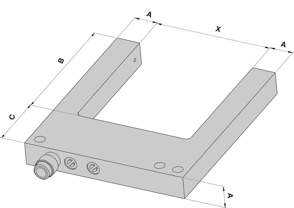
43 Sub-structure linear feeder KLF / HLF / LF Block sub-structure x D1 x D x D N G K C F H A M E B 1 Feeding technology 01
44 Technical data KLF / HLF / LF Item No. 1 - Base plate* Block 0 Block 0 Order no Dimensions Units A [mm] 0 0 B [mm] 1 0 C [mm] 0 0 D1 [mm] E [mm] D --- M8 M8 1 Item No. - Block** body 1 mm grading Order no. on request on request Dimensions Units A [mm] 0 0 F [mm] M [mm] Item No. - Bar Order no Dimensions Units A [mm] G [mm] 1 H [mm] D --- M M8 M8 K [mm]. 8 N [mm] Suitable for linear feeder: KLF KLF KLF HLF HLF HLF HLF *screwed on machine table overarm with mating dimensions E and D1 **screwed on machine table bottom up with mating dimensions M and D Note: Material: , galvanically galvanises and blue chromated. Ordering of the items depending on application. Feeding technology 01

45 1 1 1 Bowl feeder drive Feeding bowl Central fixing Mounting plate Column Clamp foot Levelling base Feeding technology 01
46 Bowl feeder drives Bowl feeder drives Bowl feeder drives BF Accessory BF Bowl feeder drives WV Accessory TS Accessory WV Sub-structure bowl feeder drives Feeding technology 01
47 Bowl feeder drives BF Compendium Accessories BF Feeding technology 01
48 BF For the attachment of the BF variants are possible: Construction with fixing plate, column and mounting attachment Construction with leveling feet Feeding technology 01
49 Bowl feeder drives BF BF10-1 A B D D1 D E1 E E D X 8 Feeding technology 01

50 Technical data BF Type BF10 BF1 Order no. Right * - 1 ** 0 V / 0 Hz Left * - 1 ** 0 V / 0 Hz Right * - 1 ** 11 V / 0 Hz Left * - 1 ** 11 V / 0 Hz Dimensions Units A [mm] B [mm] 90 D1 [mm] H H D [mm] H H D --- x M x M D --- M M E1 [mm] 1 E [mm] 8 E [mm] 0 10 X [ ] Technical data Admissible moment of inertia ±10 % 0.0 kgdm² 0.1 kgdm² Admissible bowl weight ±0 % 0.1 kg 0. kg Weight device. kg. kg Power 11 VA. VA Protection class IP IP Reactive force compensation Vibrator frequency (electric) in Hz 0/0 0/0 Mechanical vibrations per min 000/00 000/00 Scope of delivery Device Number of springs Number of spacers 1 1 = available *delivery direction (right = clockwise / left = anticlockwise) **angle of the gradient of the leaf springs Note: Refer to p. 98 for appropriate control devices. Feeding technology 01 9
51 Bowl feeder drives BF BF0-0 A B H C X1 X X D D D1 E E E1 D E D E 0 Feeding technology 01

52 Technical data BF Type BF0 BF BF0 BF BF0 BF0 Order no. Right * - 1 ** 0 V / 0 Hz Left * - 1 ** 0 V / 0 Hz Right * - 18 ** 0 V / 0 Hz Left * - 18 ** 0 V / 0 Hz Right * - 1 ** 11 V / 0 Hz Left * - 1 ** 11 V / 0 Hz Right * - 18 ** 11 V / 0 Hz Left * - 18 ** 11 V / 0 Hz Dimensions Units A [mm] B [mm] C [mm] D1 --- x M x M x M8 x M8 x M8 x M8 D [mm] H H H H H H D M M M M D [mm] --- H H H --- M8 D --- M8 M10 M10 M10 M1 M1 E1 [mm] E [mm] E [mm] E [mm] E [mm] H [mm] X1 [ ] X [ ] X [ ] Technical data Admissible moment of inertia ±10 % 1.0 kgdm². kgdm². kgdm² 8.8 kgdm² 1.0 kgdm².0 kgdm² Admissible bowl weight ±0 %.0 kg.0 kg.0 kg.0 kg 9.0 kg 0.0 kg Weight device. kg 1.0 kg 1. kg. kg. kg. kg Power 9 VA 9 VA 1 VA 1 VA 180 VA 90 VA Protection class IP IP IP IP IP IP Reactive force compensation Vibrator frequency (electric) in Hz 0/0 0/0 0/0 0/0 0/0 0/0 Mechanical vibrations per min 000 / / / / / / 00 Scope of delivery Device Number of springs Number of spacers = available = nonexistent **delivery direction (right = clockwise / left = anticlockwise) **angle of the gradient of the leaf springs Note: Refer to p. 98 for appropriate control devices. Feeding technology 01 1
53 Accessory bowl feeder drives BF Leaf spring Spacer C D 0, A B Feeding technology = nonexistent Note: Two spacers belong to one leaf spring.
54 Technical data BF Leaf spring BF10 BF1 BF0 BF Order no Dimensions Units A [mm] B [mm] 1 1 C [mm] 1 8 Leaf spring BF0 BF0 BF BF0 BF0 Order no Dimensions Units A [mm] B [mm] C [mm] Spacer BF10 BF1 BF0 BF Order no Dimensions Units A [mm] B [mm] C [mm] D [mm] Spacer BF0 BF BF0 BF0 Order no Dimensions Units A [mm] B [mm] C [mm] D [mm] Magnet BF10 BF1 BF0 BF Order no. 0 V / 0 Hz V / 0 Hz Magnet BF0 BF BF0 BF0 Order no. 0 V / 0 Hz V / 0 Hz Feeding technology 01
55 Bowl feeder drives WV Compendium Accessories WV Feeding technology 01
56 WV For the attachment of the WV variants are possible: Construction with fixing plate, column and mounting attachment Construction with leveling feet Feeding technology 01
57 Bowl feeder drives WV WV A H D E D1 Feeding technology 01

58 Technical data WV Type WV11-1 WV01-1 WV10-1 Order no. Right * - ** Left * - ** Right * - 0 ** Left * - 0 ** Dimensions Units A [mm] D1 --- M M8 M8 D --- x M x M x M E [mm] H [mm] Technical data Admissible bowl weight 1.1 kg.0 kg. kg Elec. configuration *** 0 V / 0 Hz 0 V / 0 Hz 0 V / 0 Hz Weight device.0 kg 1.0 kg.0 kg Power VA 1 VA 1 VA Protection class IP IP IP Vibrator frequency (electric) in Hz Mechanical vibrations per min Scope of delivery Device Number of springs Number of spacers = available = nonexistent *delivery direction (right = clockwise / left = anticlockwise) **angle of the gradient of the leaf springs ***other electr. configurations on request Note: Refer to p. 98 for appropriate control devices. Feeding technology 01
59 Bowl feeder drives WV Compendium Accessories WV Feeding technology 01
60 WV Attachment of WV 01 and 0 Construction with leveling feet Feeding technology 01 9
61 Bowl feeder drives WV WV 01-0 A1 A M A K L D H D D1 E1 E D E E D X X X1 0 Feeding technology 01

62 Technical data WV Type WV01-1 WV0-1 Order no. Right * 0 V / 000 vpm ** Left * 0 V / 000 vpm ** Right * 0 V / 000 vpm ** Left * 0 V / 000 vpm ** Right * 11 V / 00 vpm ** Left * 11 V / 00 vpm ** Right * 11 V / 00 vpm ** Left * 11 V / 00 vpm ** Dimensions Units A1 [mm] 0 0 A [mm] A [mm] D1 [mm] 8 x 9 8 x 9 D [mm] x 8H x 8H D --- x M10 x M10 D x M 1 x M D --- x M8 x M8 E1 [mm] E [mm] 0 0 E [mm] 0 0 E [mm] 0 0 H [mm] K [mm] L [mm].0.0 M [mm] X1 [mm] 1 1 X [mm] 1 1 X [mm] 0 0 Technical data Admissible bowl weight 0 kg 0 kg Weight device 10 kg 10 kg Power 10 VA 118 VA Protection class IP IP Scope of delivery Device Number of springs Number of spacers 8 8 = available = nonexistent *delivery direction (right = clockwise / left = anticlockwise) **vibrator frequency (Vibrations per minute in half-wave mode respectively full-wave mode) Note: Refer to p. 98 for appropriate control devices. For the central fixation of a feeding bowl a adapter plate (see page ) is required. Feeding technology 01 1
63 Bowl feeder drives WV Mounting options WV01-1 and WV0-1 Radial attachment 1 1 Attachment from above 1 1 Attachment from below 1 1 Adapter plate for central fixation 1 1 Feeding technology 01
64 Technical data WV / TS Notation 1 Drive Bowl Bolt Adapter plate Accessory Adapter plate TS0-1 centrical fixation D A Adapter plate TS0-1 Order no. Centrical fixation 010 Dimensions Units A [mm]. D [mm] 0 Feeding technology 01

65 Accessory bowl feeder drives WV Leaf spring Spacer A A C C B WV01-10 WV01-0 Feeding technology 01
66 Technical data WV Leaf spring WV11-1 WV01-1 WV10-1 WV01-1 WV0-1 Order no Dimensions Units A [mm] 0. B [mm] C [mm] Order no Dimensions Units A [mm] B [mm] C [mm] Spacer WV11-1 WV01-1 WV10-1 WV01-1 WV0-1 Order no Dimensions Units A [mm] B [mm] C [mm] Magnet WV11-1 WV01-1 WV10-1 WV01-1 WV0-1 Order no. 0 V / 0 Hz V / 0 Hz on request on request on request = nonexistent Note: Two spacers belong to one leaf spring. Feeding technology 01
67 Sub-structure bowl feeder drives BF / WV Item No. 1 - Mounting plate* A 1 B C A For BF C For WV 1 Item No. - Column** 10 mm grading N E H F L G K L O D Item No. - Clamp foot* M *material , galvanically galvanises and blue chromated **material 1.0, blanc Feeding technology 01
68 Technical data BF / WV Item No. 1 - Mounting plate* BF 10 BF 1 BF 0 BF Order no Dimensions Units A [mm] B [mm] C [mm] PosNr. 1 - Mounting plate** BF 0 BF BF 0 BF 0 Order no Dimensions Units A [mm] B [mm] C [mm] PosNr. 1 - Mounting plate** WV11-1 WV01-1 WV10-1 Order no Dimensions Units A [mm] B [mm] C [mm] Item No. - Column** Order no. on request Dimensions Units D [mm] L 10 mm grading [mm] 0 10 N [mm] 8 O [mm] Item No. - Clamp foot* Low High Order no Dimensions Units E [mm] 1 1 F [mm] 0 G [mm] 0 0 H [mm] 0 K [mm] 1 1 L [mm] 1 1 M [mm] = nonexistent Note: Ordering of the items depending on application. Feeding technology 01
69 Sub-structure bowl feeder drives BF / WV Assembly accessory 1 Levelling base* A B F E D C 8 Feeding technology 01
70 Technical data BF / WV Assembly accessory Notation 1 Levelling base Spacer Bowl feeder drive Levelling base* Short Long Large Order no Required number of levelling base for: BF10 to BF0 --- BF0 WV11-1 to WV WV00 Order no. Spacer ** mm Spacer ** 10 mm Spacer ** 0 mm Dimensions Units A [mm] B [mm] C [mm] D [mm] E [mm].. 0 F [mm] Scope of delivery Levelling base Spacer mm * material: , galvanically galvanises and blue chromated **material: 1.018, galvanically galvanises and blue chromated = available Feeding technology 01 9

71 1 1 1 Feeding bowl Spring washer set Adapter plate Bowl feeder drive 0 Feeding technology 01
72 Feeding bowls Feeding bowls Blank bowl BB Step helix BB-S Groove helix BB-N Radius helix BB-R Stepped bowls TS 8 Accessory feeding bowls 80 Feeding technology 01 1
73 S Feeding bowls BB Blank bowl Ø D1 Ø D W H h Ø D Ø D Feeding technology 01
74 Technical data BB Blank bowl BB10 BB1 BB0 BB BB0 Order no. Polyamide FDA-Polyamide (white) Dimensions Units D1 [mm] D [mm] D [mm] D [mm] H [mm] 8 98 h [mm] S [mm] W [ ] Technical data Load volume * [l] Weight [kg] Moment of inertia [kg * dm²] Recommended drive BF10 BF1 WV11-1 BF0 WV11-1 BF WV01-1 BF0 WV01-1 Blank bowl BB BB0 BB0 BB Order no. Polyamide FDA-Polyamide (white) Dimensions Units D1 [mm] D [mm] D [mm] D [mm] H [mm] 1 1 h [mm] S [mm].. 0 W [ ] Technical data Load volume * [l] Weight [kg].9 8,9 1,. Moment of inertia [kg * dm²] Blind plug polyamide including Blind plug FDA-polyamide including Recommended drive BF WV10-1 BF0 BF0 WV01-1 WV0-1 *theoretical value, current load volume largely dependent on the component to be fed and the specific project conditions Note: Conical spring washer see page 80. Feeding technology 01
75 Feeding bowls BB-S E F 10 S A H C B TH ØTD A L A Step helix BB10-S BB1-S BB0-S BB-S BB0-S BB-S BB0-S BB0-S Order no. Right * Left * Right - FDA Left - FDA Dimen. Units S [mm] A [mm] B [mm] H [mm] C [mm] E [mm] F [mm] L [mm] TH [mm] TD [mm] *delivery direction (right = clockwise / left = anticlockwise) Note: Recommended drives and further information, see p.. Bowl with FDA-certification on demand. Feeding technology 01
76 Feeding bowls BB-N E F 1 0 A B C TH H S A L A ØTD Groove helix BB10-N BB1-N BB0-N BB-N BB0-N BB-N BB0-N BB0-N Order no. Right * Left * Right - FDA Left - FDA Dimen. Units S [mm] A [mm] B [mm] H [mm] C [mm] E [mm] F [mm] L [mm] TH [mm] TD [mm] *delivery direction (right = clockwise / left = anticlockwise) Note: Recommended drives and further information, see p.. Bowl with FDA-certification on demand. Feeding technology 01
77 Feeding bowls BB-R F 0 C TH H S R ØTD A L A Radius helix BB10-R BB1-R BB0-SR BB-R BB0-R BB-R BB0-R BB0-R Order no. Right * Left * Right - FDA Left - FDA Dimen. Units S [mm] R [mm] H [mm] C [mm] F [mm] L [mm] TH [mm] TD [mm] *delivery direction (right = clockwise / left = anticlockwise) Note: Recommended drives and further information, see p.. Bowl with FDA-certification on demand. Feeding technology 01
78 Feeding technology 01

79 Feeding bowls TS TS0-1 TS0-1 8 Feeding technology 01
![Technical data TS Stepped bowls TS0-1 TS0-1 Order no. Right * 11008 01 ** Left * 11008 018 ** Fixation Centrical Centrical Dimensions Units ø A [mm] ø B [mm] 8.](/docs-images/74/69886063/images/80-0.jpg "18 C [mm] 0 0 D [mm] 110 1 E [mm] 0 F [mm] 8 ø G [mm] 90 0 H [mm] 10 1 K [mm] Technical data Weight. kg 1.0 kg Load volume ***.")
80 Technical data TS Stepped bowls TS0-1 TS0-1 Order no. Right * ** Left * ** Fixation Centrical Centrical Dimensions Units ø A [mm] ø B [mm] C [mm] 0 0 D [mm] E [mm] 0 F [mm] 8 ø G [mm] 90 0 H [mm] 10 1 K [mm] Technical data Weight. kg 1.0 kg Load volume ***.00 L 10 L Recommended drive BF WV10-1 WV01-1 WV0-1 *delivery direction (right = clockwise / left = anticlockwise) **an adapter plate is necessary for fixation, see page ***theoretical value, current load volume largely dependent on the component to be fed and the specific project conditions Note: Material: Aluminium. Conical spring washer see page 80. Feeding technology 01 9
81 Accessory feeding bowls BB / TS Centrical fixation 1 Spring washer set H B D A Counterweight A S R D 8 0 Feeding technology 01
82 Technical data BB / TS Centrical fixation Notation 1 Bowl feeder drive Feeding bowls Spring washer set Spring washer set BB0 BB BB0 BB BB0 BB0 Order no. uncoated coated Dimensions Units A [mm] B [mm] D --- M8 M10 M10 M10 M1 M1 H [mm] Counterweight BB0 BB BB0 BB BB0 BB0 Order no Dimensions Units A [mm] R [mm] S [ ] D [mm] Weight [g] Note: Material: 1.01 Feeding technology 01 81

83 1 1 NVB NVD 8 Feeding technology 01
84 Refilling units Refilling units Refillable vibratory hopper NVB 8 Vibratory hopper NVD 8 Accessory NVD 8 Conveyor belt hopper NBB 88 Accessory NBB 90 Feeding technology 01 8
85 Refilling units NVB Refillable vibratoy hopper NVB A E C B F D 8 Feeding technology 01
86 Technical data NVB Refillable vibratoy hopper NVB0/0. NVB1/1.0 NVB/.0 Order no. 0 V / 0 Hz V / 0 Hz Dimensions Units A [mm] B [mm] C [mm] D [mm] 8 8 E [mm] F [mm] 8 1 Technical data Filling volume 0. l 1.0 l.0 l Maximum filling weight 1. kg. kg 9.0 kg Voltage 0/11 VAC 0/11 VAC 0/11 VAC Surface roughness R a < 0.8 μm < 0.8 μm < 0.8 μm Surface roughness R z <. μm <. μm <. μm Frequency 0/0 Hz 0/0 Hz 0/0 Hz Protection class IP IP IP Vibrator frequency (electric) in Hz 0/0 0/0 0/0 Vibrations mécaniques par min 000/00 000/00 000/00 Feeding technology 01 8


87 Refilling units NVD Vibratory hopper unit NVD Vibratory hopper unit NVD 8 Feeding technology 01

88 Technical data NVD Vibratory hopper unit NVD/ NVD/10 NVD/1 NVD/0 NVD/0 Order no. 0 V / 0 Hz V / 0 Hz Dimensions Units A [mm] B [mm] C [mm] D [mm] E [mm] F [mm] G [mm] H [mm] I [mm] K [mm] L [mm] 9 8 M [mm] N --- M M M M M O --- M10 M10 M10 M10 M10 P [mm] S [mm] Unit X L [mm] on request on request on request on request on request Technical data Filling volume.0 l 10.0 l 1.0 l 0.0 l 0.0 l Filling weigth kg 0 kg 0 kg 0 kg 0 kg Power input 0. A 0.8 A 0.8 A 0.8 A 0.8 A Voltage 0 VAC 0 VAC 0 VAC 0 VAC 0 VAC Frequency 0/0 Hz 0/0 Hz 0/0 Hz 0/0 Hz 0/0 Hz Surface roughness R a < 0.8 μm < 0.8 μm < 0.8 μm < 0.8 μm < 0.8 μm Surface roughness R z <. μm <. μm <. μm <. μm <. μm Protection class IP IP IP IP IP Vibrator frequency [Vibrations per min] 000/ / / / / 00 Accessory refilling units Type NVD/ NVD/10 NVD/1 NVD/0 NVD/0 Order no. Item No. 1 Base plate Item No. Joint clamp ** Item No. Column ** on request on request on request on request on request Item No. Column support ** = nonexistent * material: 1.01 ** needed x for type NVD Note: Refer to p. 98 for appropriate control devices. Feeding technology 01 8
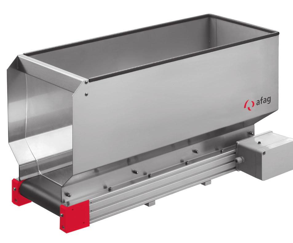
89 Refilling units NBB Conveyor belt hopper NBB10-0 H K C O B A N D G F M E Dashed illustration: Heavy load design 8 8 Feeding technology 01

90 Technical data NBB Conveyor belt hopper NBB10 NBB0 NBB0 Order no. VDC Standard V / 0 Hz Standard V / 0 Hz Heavy load V / 0 Hz Standard V / 0 Hz Heavy load Dimensions Units A [mm] B [mm] 00 0 C [mm] 0 D [mm] E [mm] F [mm] G [mm] H [mm] max. max. max. K --- M8 M8 M8 M [mm] N [mm] O [mm] Technical data Filling volume 10 l 0 l 0 l Filling weight standard 0 kg 0 kg 0 kg Filling weight heavy load 0 kg 0 kg 0 kg Belt speed 0.1 m/min 0.1 m/min 0.1 m/min Weight device 19.0 kg 0.10 kg 9.00 kg Power output: VDC Standard W W W 0 VAC Standard W W W 0 VAC Heavy load 11 W 11 W 11 W 11 VAC Standard W W W 11 VAC Heavy load 99 W 99 W 99 W Power input: VDC Standard 0. A 0. A 0. A 0 VAC Standard 0.1 A 0.1 A 0.1 A 0 VAC Heavy load 0. A 0. A 0. A 11 VAC Standard 0. A 0. A 0. A 11 VAC Heavy load 0.9 A 0.9 A 0.9 A Protection class standard IP IP IP Protection class heavy load IP IP IP Note: Outlet refer to page 90. Feeding technology 01 89
91 Accessory refilling units NBB Outlet shaft C A B Outlet slide F E D 9 0 Feeding technology 01
92 Technical data NBB Outlet NBB10 NBB0 NBB0 Order no. Outlet shaft Outlet slide Dimensions Units A [mm] B [mm] 9 C [mm] D [mm] E [mm] F [ ] Note: Material: Feeding technology 01 91
93 Accessory refilling units NBB Conveyor belt hopper stand E O N K F D A C B L G H M Assembly layout NBB 1 9 Feeding technology 01
94 Technical data NBB Item No. 1 - Single column support* Order no Dimensions Units A [mm] 10 B [mm] 8 C [mm] 11 K [mm] M [mm] O [mm] Item No. - Intermediate plate** Order no Dimensions Units D [mm] 10 E [mm] 0 F [mm] 180 G [mm] 9 N [mm] 10 Item No. - Round*** 0 mm grading Order no. on request Dimensions Units L [mm] H [mm] *material:.1, required twice ** material: , galvanically galvanises and blue chromated ***material: 1.0 Feeding technology 01 9
95 Accessory refilling units NBB Extension plate* B C A E D 9 Feeding technology 01
96 Technical data NBB Extension plate* Order no. 001 Dimensions Units A [mm] 100 B [mm] 00 C [mm] 0 D [mm] 1 E [mm] 8 *for fixation of 1 x Refilling unit NBB10-0 with support Note: Other dimensions on demand. Material , galvanically galvanises and blue chromated. Feeding technology 01 9

97 1 1 Control device Smart Box Phase angle controller IRG1-S Motor controller IRG1-MS Fixation 1-IRG Fixation -IRG Control device SIGA 9 Zuführtechnik 01
98 Control devices Control devices Phase angle controller IRG1-S 98 Motor controller IRG1-MS 100 Control device Smart Box 10 Accessoires IRG / Smart Box 10 Control device SIGA 10 Zuführtechnik 01 9
99 Control devices IRG Phase angle controller IRG1-S B C D E A 9 8 Feeding technology 01
 Output electric voltage 0 V (11 V) Output electric current A AC Vibrator")
100 Technical data IRG Phase angle controller IRG1-S Order no. 0 V V 0010 Dimensions Units A [mm] 1 B [mm] 80 C [mm] 0 D [mm] E [mm] Technical data Input electric voltage 0 V (11 V) Output electric voltage 0 V (11 V) Output electric current A AC Vibrator Conveyoer belt hopper NBB --- Vibratory hopper unit NVD 0 VAC (11 VAC) 0-8 VAC (0-100 VAC) External target value preset 0-0 ma (DC) 0-10 VDC Smooth start 0 - s Operating mode display LED Alternation operation Continous operation Input of optical coupler invertable Temperature range 0 - C Supply voltage compensatio Plug connector / pins M8 / Degree of protection IP = available = nonexistent Feeding technology 01 99
101 Control devices IRG Motor controller IRG1-MS B C A E D Feeding technology 01
![Technical data IRG Motor controller IRG1-MS Order no. 0 V / 11 V 091018 Dimensions Units A [mm] 1 B [mm] 80 C [mm] 1.](/docs-images/74/69886063/images/102-0.jpg "D [mm] 10 E [mm] Technical data Supply voltage 0/11 VAC Frequency 0/0 Hz Enable input VDC Motor output 0/11 VAC; A Vibrator Conveyor belt hopper NBB --- Vibratory hopper")
102 Technical data IRG Motor controller IRG1-MS Order no. 0 V / 11 V Dimensions Units A [mm] 1 B [mm] 80 C [mm] 1. D [mm] 10 E [mm] Technical data Supply voltage 0/11 VAC Frequency 0/0 Hz Enable input VDC Motor output 0/11 VAC; A Vibrator Conveyor belt hopper NBB --- Vibratory hopper NVD Degree of protection IP Feeding technology
103 Control devices Smart Box Control device Smart Box B C D E A Connection options for the Smart Box Additionally may be connected to the Smart Box: - Blast air to 00 ma - System Release (invertible) - Error message (lamp) 1 0 Feeding technology 01
![Technical data Smart Box Control device Smart Box Order no. 0 V / 11 V 018 Dimensions Units A [mm] 1 B [mm] 80 C [mm] 1.](/docs-images/74/69886063/images/104-0.jpg "D [mm] 10 E [mm] Technical data Output electric voltage V Conveyor outputs x M8 / Sensor inputs x M8 / Max. current sensor 1 A Blast air valve M8 / Max.")
104 Technical data Smart Box Control device Smart Box Order no. 0 V / 11 V 018 Dimensions Units A [mm] 1 B [mm] 80 C [mm] 1. D [mm] 10 E [mm] Technical data Output electric voltage V Conveyor outputs x M8 / Sensor inputs x M8 / Max. current sensor 1 A Blast air valve M8 / Max. current blast air valve 00 ma Multi-function output M8 / System release M8 / Short-circuit proof Operating mode display LED Temperature range 0 - C Degree of protection IP Operating voltage 11/0 VAC Fuses MA / 0 V Control input + VDC = available Feeding technology 01 10
105 1 0 Feeding technology 01 A B E C B C A F D A A B D F E C B A C IRG / Smart Box Accessory control devices Alternative assembly variants Fixation of control device IRG
106 Technical data IRG / Smart Box Alternative assembly variants for accessory IRG Notation 1 Control device Fixation-1-IRG Base plate Fixation for 1-IRG -IRG Order no Dimensions Units A [mm] 0 0 B [mm] 0 0 C [mm] D [mm] E [mm] F [mm] Technical data Capability of fixation (quantity of control devices) 1 Note: Material stainless steel. Feeding technology 01 10
107 Control devices SIGA Contol device SIGA B C D E A 1 0 Feeding technology 01

108 Technical data SIGA Contol device SIGA Order no. 0 V V 000 Dimensions Units A [mm] 00 B [mm] 100 C [mm] 80 D [mm] E [mm] 0 Technical data Input voltage 0 VAC Frequency 0/0 Hz Output voltage VAC Output current A Output frequency...00 Hz Degree of protection IP Fuses x. A (F) Ambient temperature 0 0 C Feeding technology 01 10


109 Base frame Base plate Fixation for control device IRG Pendulum sensor Bowl cover Block body for linear feeder Linear feeder HLF 8 Sensor fixation buffer control 9 Fork light barrier Zuführtechnik 01
110 Afag-Chrome-Line feeding components Afag-Chrome-Line feeding components Feeding station 110 Base plate 11 Base frame GG 11 Buffer control 11 Light barrier GL 118 Level control device 10 Collecting container 1 Bowl cover 1 Zuführtechnik
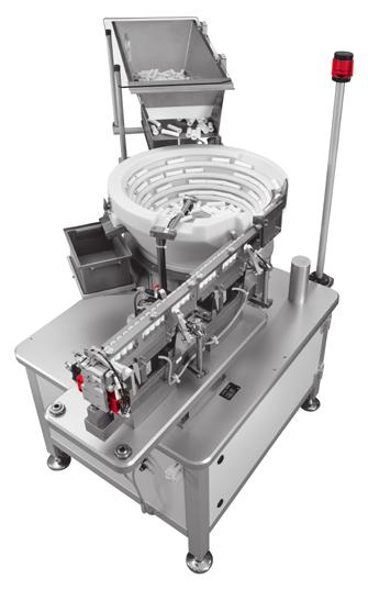
111 Afag-Chrome-Line feeding components ACL Feeding station Feeding technology 01

112 Technical data ACL Item No. Notation Page 1 Linear feeder and accessory 8 Bowl feeder drive and accessory Feeding bowl and accessory 0 Refilling unit and accessory 8 Control device and accessory 9 Afag-Chrome-Line feeding components Base plate 11 Base frame 11 8 Buffer control 11 9 Level control device Bowl cover 1 Feeding technology
113 Afag-Chrome-Line feeding components Base plate A B 1 1 Feeding technology 01
114 Technical data Base plate for bowl feeder KLF, HLF0 KLF1, HLF1 KLF, HLF AxB [mm x mm] AxB [mm x mm] AxB [mm x mm] BF10 10 x BF1, WV11 00 x BF0, WV01 0 x BF 10 x 0 00 x BF0, WV01, WV10 0 x 0 0 x BF x BF x BF x WV x x 90 Note: Recommended base plate dimensions for combination of linear feeder with bowl feeder; Material: , blue chromated; Thickness 0 mm; customer-specific hole pattern for application; other dimensions on request = nonexistent = existent Note: Other dimensions on demand. Material , galvanically galvanises and blue chromated. Feeding technology 01 11
115 Afag-Chrome-Line feeding components GG Base frame GG A E C G D B F H 1 1 Feeding technology 01
![Technical data GG Base frame 00 x 00 00 x 00 00 x 00 00 x 00 Dimensions Units A [mm] 80 0 0 0 B [mm] 00 00 00 00 C [mm] 0 0 0 0 D [mm] 100 E [mm] 10 0 10 90 F [mm] 1 1 1 8 G - M10 M10 M10 M10 H - M1](/docs-images/74/69886063/images/116-0.jpg "M1 M1 M1 Base frame 00 x 00 800 x 800 900 x 900 1000 x 1000 Dimensions Units A [mm] 0 0 80 90 B [mm] 00 00 00 00 C [mm] 0 0 0 0 D [mm] 100 100 100 100 E [mm] 90 10 0 810 F [mm] 8 8 8 8 G - M10 M10")
116 Technical data GG Base frame 00 x x x x 00 Dimensions Units A [mm] B [mm] C [mm] D [mm] 100 E [mm] F [mm] G - M10 M10 M10 M10 H - M1 M1 M1 M1 Base frame 00 x x x x 1000 Dimensions Units A [mm] B [mm] C [mm] D [mm] E [mm] F [mm] G - M10 M10 M10 M10 H - M1 M1 M1 M1 Feeding technology 01 11
117 D Afag-Chrome-Line feeding components ACL Buffer control C 8 B A G D C 8 H 1 x F E 1 1 Feeding technology 01
 * ) Item No. Round 0 mm grading on request on request Item No. 8 Round 0 mm grading on request on request with fork Dimensions Units A [mm] 8.")
118 Technical data ACL Buffer control Order no. with clamp foot Item No. 1 Clamp foot Item No. Fork Item No. Cross-type clamp Item No. Clamping cylinder Item No. Retainer plate Item No. Fork light barrier * ) * ) Item No. Round 0 mm grading on request on request Item No. 8 Round 0 mm grading on request on request with fork Dimensions Units A [mm] 8. B [mm] 9 C [mm] 0 D [mm] 1 E [mm] x F [mm]. G [mm] H [mm] *refer to page 119 Note: Ordering of the items depending on application; Connection cable not in scope of delivery. Feeding technology 01 11
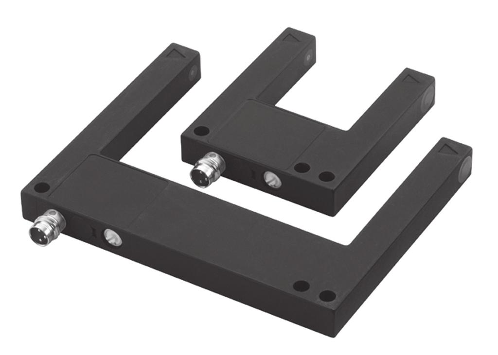

119 Afag-Chrome-Line feeding components ACL Fork light barrier Feeding technology 01
120 Technical data ACL Fork light barrier GL0 GL0 GL0 GL80 GL10 Order no Dimensions Units X [mm] A [mm] B [mm] 0 C [mm] 0 Technical data Voltage 10 V DC 10 V DC 10 V DC 10 V DC 10 V DC Output pnp/no/nc pnp/no/nc pnp/npn pnp/npn pnp/npn Power rating Short-circuit resistant 00 ma 00 ma 00 ma 00 ma 00 ma Current consumption < 0 ma < 0 ma < ma < 0 ma < ma Voltage drop <.8 V <.8 V <.8 V <.8 V <.8 V Control frequency khz khz khz khz khz Resolution 0. mm 0. mm 0. mm 0. mm 0.8 mm Control hysteresis < 0. mm < 0. mm < 0. mm < 0. mm < 0. mm Reproducability 0.0 mm 0.0 mm 0.0 mm 0.0 mm 0.0 mm Ambient temperature C C C C C Fault light safety 10 klux 80 klux 80 klux 80 klux 0 klux Max. voltage for insulating power 00 V 00 V 00 V 00 V 00 V Degree of protection IP IP IP IP IP Cabinet material * ) ** ) * ) * ) * ) Connector three pins three pins three pins three pins three pins Fitting of the connector M8 M8 M8 M8 M8 *zinc pressure die cast (black-chromium-plated) **aluminium (black-oxidized electr.) Note: Light barriers with other fork opening dimension on demand; Connection cable not in scope of delivery. Feeding technology
121 Afag-Chrome-Line feeding components ACL Sensor fixation fuel level meter inductive H D G 8 F C E A 1 B Holder for fill level reflection detector D H G E A 1 B 1 0 Feeding technology 01
 --- 00111 Item No. Round 0 mm grading --- on request Item No.")
122 Technical data ACL Track level control Inductive Reflection Order no. Item No. 1 Clamp foot Item No. Cross-type clamp Item No. Clamping cylinder Item No. Retainer plate Item No. Pendulum-queries Item No. Sensor (Omron) Item No. Round 0 mm grading --- on request Item No. 8 Round 0 mm grading on request on request Dimensions Units A [mm].. B [mm] C [mm] D [mm] 1 1 E [mm] 0 0 F [mm] --- G [mm] H [mm] Technical data Measurement distance --- max. 00 mm Nominal operating range mm --- Temperature range Plug connector / pins M8 / M8 / Degree of protection IP IP Range of Voltage rating 10 0 V DC 1 VDC Max. Load circuit 00 ma 0 ma --- = nonexistent Note: Ordering of the items depending on application; Connection cable not in scope of delivery. Feeding technology 01 11
123 Afag-Chrome-Line feeding components ACL Collecting container large D E C F B H 1 A Collecting container small C E D H F B A 1 1 Feeding technology 01

124 Technical data ACL Collecting container large small Order no. Item No. 1 Clamp foot Item No. Hopper holding device Item No. Clamping arm Item No. Hopper * Item No. Round 0 mm grading on request on request Item No. Fork Dimensions Units A [mm] B [mm].. C [mm] 10 8 D [mm] 10 8 E [mm] 0 F [mm] 0 0 H [mm] *Hopper colour: red, other colours on request Note: The individual parts are to be ordered in line with the required size of hopper and length of tube. Feeding technology 01 1
125 Afag-Chrome-Line feeding components ACL Bowl cover C 1 B D A Lateral rotatable Hinged 1 Feeding technology 01

126 Technical data ACL Bowl cover Notation 1 Bowl cover Prop for cover Mounting plate Bowl feeder drive Feeding bowl Bowl cover BB1 BB0 BB BB0 BB BB0 BB0 Lateral rotatable Hinged Order no. Prop for cover * Dimensions Units A [mm] B [mm] D +. D +. D +. D +. D +. D +. D +. C [mm] D [mm] *for BB0 to BB0 included in delivery --- = nonexistent Note: Material cover: macrolon limpid; Mounting plates see page 8. Feeding technology 01 1

127 1 1 Aflex Flipconveyor 1 Feeding technology 01
128 Flex Feeding Flex Feeding Aflex 18 Flipconveyor 10 Feeding technology 01 1
129 Flex Feeding Aflex aflex 00 A B D L N C O F K E H I M G 1 8 Feeding technology 01
130 Technical data Aflex Type aflex 10 aflex 00 Order no. with vibrationplate POM white 0 0 with vibrationplate POM black 08 0 with vibrationplate PTFE white 09 0 with backlight and vibrationplate POM white 00 0 with backlight and vibrationplate PTFE white 01 0 with textured vibrationplate 0 08 Dimensions Units A [mm] 10 9 B [mm] 10 0 C [mm] 10 0 D [mm] E [mm]. 90. F [mm] 1 1 G [mm] ø18 ø18 H [mm] ø1 ø1 I [mm] K [mm].. L [mm] M [mm] N [mm] 10 O [mm] 1 Technical data Max. part size < 10 mm < 0 mm Max. part weight < g < 0 g Control voltage V V Total current [max] 10 A 10 A Recommended pre-fuse C10A / 10A GL T C10A / 10A GL T Relative activation duration of the actuators < 1% < 1% Ambient temperature 0 80 C 0 80 C Weight kg. kg Standard interface Multi I/O, Ethernet Multi I/O, Ethernet Optional interface Profibus Profibus Integrated background lighting optional optional Protection type IP IP Feeding technology 01 19
131 Flex Feeding Flipconveyor Flipconveyor A F D E B C G 1 0 Feeding technology 01

![part size < 0 mm < 0 mm Max. part weight < g < g Control voltage V V Total current [max] A A Recommended pre-fuse (for individual protection) BA BA Ambient temperature 0 0 C 0 0 C Weight. kg.](/docs-images/74/69886063/images/132-1.jpg "kg Interface belt and brushed motor Faulhaber adapter (optional) Faulhaber adapter (optional) Interface Flip motor controller Serial (RS-) Serial (RS-) Integrated belt lighting optional")
132 Technical data Flipconveyor Type Flipconveyor 00 Flipconveyor00 Order no. Flipconveyor with black belt Flipconveyor with white belt 00 0 Dimensions Units A [mm] B [mm] 8 8 C [mm] D [mm] E [mm] F [mm] 8 8 G [mm] Technical data Max. part size < 0 mm < 0 mm Max. part weight < g < g Control voltage V V Total current [max] A A Recommended pre-fuse (for individual protection) BA BA Ambient temperature 0 0 C 0 0 C Weight. kg. kg Interface belt and brushed motor Faulhaber adapter (optional) Faulhaber adapter (optional) Interface Flip motor controller Serial (RS-) Serial (RS-) Integrated belt lighting optional optional Protection type IP IP Accessory Frame flipzone Flipconveyor 00 Flipconveyor 00 Order no. 0 0 Feeding technology 01 11

133 1 1 Laboratory instrument QRG1 Handheld demagnetizer HEM 1 Zuführtechnik 01
134 Diagnostics and training Diagnostics and training Workshop and training 1 Laboratory instrument QRG1 1 Handheld demagnetizer HEM 18 8 Zuführtechnik 01 1


135 Afag workshops for practitioners d m c F M (t) Vibration Technology Basics Our success is based on vibration technology. As technology leader in the field of vibration conveying technology, we bring the necessary knowledge for the application into your company. Use of Afag Products Correct handling of our products enables maximum performance and precision. Due to training in their assembly, you can use the possibilities of our equipment optimally for your application. 1 Feeding technology 01


136 8 Troubleshooting and Tips & Tricks for Practitioners You can benefit from our many years of experience in the design and manufacture of part feeders. We show you how you sustainably optimise your systems from the installation to the operation. Please visit our website for further information. www. Feeding technology 01 1
137 Laboratory instrument QRG Laboratory instrument QRG1 A B E D F C 1 Feeding technology 01
![Technical data QRG Laboratory instrument QRG1 Order no. 110 / 10 / 0 / 0 V 090 Dimensions Units A [mm] B [mm] 1 C [mm] D [mm] 8.](/docs-images/74/69886063/images/138-0.jpg "E [mm] F [mm] 8 Technical data Power section: Output voltage 0 10 / 0 0 V Input voltage 110/10/0/0 V Frequency 0/0 Hz Output current 8 A Output frequency 00 Hz Measurement section: Actual values")
138 Technical data QRG Laboratory instrument QRG1 Order no. 110 / 10 / 0 / 0 V 090 Dimensions Units A [mm] B [mm] 1 C [mm] D [mm] 8. E [mm] F [mm] 8 Technical data Power section: Output voltage 0 10 / 0 0 V Input voltage 110/10/0/0 V Frequency 0/0 Hz Output current 8 A Output frequency 00 Hz Measurement section: Actual values sensor 10/100/00 mv/g Sensor supply 1 ma Frequency 00 Hz Deflection 0 0 mm Measuring range g Measuring error 1. % Accessory Accelerometer Order no. 099 Note: on controller selection: Controller PSG1 usable only with HLF-P. Feeding technology 01 1
139 Handheld demagnetizer HEM Handheld demagnetizer HEM B A C 1 8 Feeding technology 01

140 Technical data HEM Handheld demagnetizer HEM Order no. 0 V / 0 Hz V / 0 Hz 0 Dimensions Units A [mm]. B [mm] 0 C [mm] 90 8 Technical data Weight Power Protection class 0. kg 1 VA IP0 Feeding technology 01 19

. Protects against soiling.")
141 Project-specific components FB / LSH Conveyor Belts FB 1. Fast and efficient transport and separation. Flexible motor arrangement and easy installation. Available with brake/clutch unit Conveyor Belts FB Noise reduction cover LSH 1. Reduces the noise level by up to 0 db(a). Protects against soiling. Also available with plastic coating Noise reduction cover LSH 1 0 Feeding technology 01

142 Solutions to untangle springs TF / FEG Drum feeder 1. Disentanglement and separation of springs and other bulk materials. Stand-alone operation with integrated control. Custom expandability of the base unit to a variety of solutions 9 Drum feeder Spring feeder device FEG 1. Disentanglement and feeding of flat spiral springs. Simple operation via small controller. Reduces assembly costs Spring feeder device FEG Feeding technology 01 11
143 Drum feeder TF Drum feeder B A D C 1 Feeding technology 01
![Technical data TF Drum feeder Order no. 0 V / 0 Hz on request Dimensions Units A [mm] 0 B [mm] C [mm] 10 D [mm].](/docs-images/74/69886063/images/144-0.jpg "9 Technical data Voltage supply 0 VAC Power rating 00 VA Power fuse 10 A Rated current A Internal voltage supply VDC,.")
144 Technical data TF Drum feeder Order no. 0 V / 0 Hz on request Dimensions Units A [mm] 0 B [mm] C [mm] 10 D [mm]. 9 Technical data Voltage supply 0 VAC Power rating 00 VA Power fuse 10 A Rated current A Internal voltage supply VDC,. A Supply pressure bar / 8 psi Pneumatic connection Festo KSS Drum diameter 00 Temperature range 0-0 C Supply voltage compensation Degree of protection IP = available Feeding technology 01 1
1 Linear feeder 2 Track 3 Cover 4 Side plate 5 Trim weight 6 Sub-structure. 8 Feeding technology afag.com
 Linear feeder Track Cover Side plate Trim weight Sub-structure 8 Feeding technology 0 Linear feeder Linear feeder Linear feeder HLF-M Linear feeder HLF-P 8 Control devices PSG Accessory HLF Linear feeder
NR ROTARY RING TABLE: FLEXIBLE IN EVERY RESPECT
 NR FREELY PROGRAMMABLE ROTARY TABLES NR ROTARY RING TABLE All NR rings allow customer-specific drive motors to be connected NR ROTARY RING TABLE: FLEXIBLE IN EVERY RESPECT WHEN IT S GOT TO BE EXACT We
Rotary modules.
 Rotary modules www.comoso.com www.comoso.com Rotary modules ROTARY MODULES Series Size Page Rotary modules RM swivel unit 156 RM 08 160 RM 10 162 RM 12 164 RM 15 168 RM 21 172 RM rotor 176 RM 50 180 RM
T20WN. Data Sheet. Torque transducers. Special features. Installation example with bellows couplings. B en
 T20WN Torque transducers Data Sheet Special features - Nominal (rated) torques 0.1 N m, 0.2 N m, 0. N m, 1 N m, 2 N m, N m, 10 N m, 20 N m, 0 N m, 100 N m, 200 N m - Accuracy class: 0.2 - Contactless transmission
Selection table for guided systems (crank driven)
") Selection table for guided systems (crank driven) One mass shaker brute-force system One mass shaker natural frequency system Two mass shaker fast-runner system with reaction force-compensation Single
Selection table for guided systems (crank driven) One mass shaker brute-force system One mass shaker natural frequency system Two mass shaker fast-runner system with reaction force-compensation Single
Product description. Compact Modules. Characteristic features. Further highlights
 4 Compact Modules Product description Characteristic features Five fine-tuned sizes based on a compact precision aluminum profile with two integrated pre-tensioned ball rail systems Identical external
Conductivity sensor for hygienic applications
 Conductivity sensor for hygienic applications Type 8221 can be combined with Perfect for demanding applications in the hygienic industry (CIP and SIP compatible) Variants available for usage over a wide
BETA Protecting. Low-Voltage Fuse Systems. LV HRC fuse links. 3/36 Siemens ET B1 2008
 LV HRC fuse links Overview LV HRC fuses are used for installation systems in non-residential, commercial and industrial buildings as well as in switchboards of power supply companies. They therefore protect
Cabinets G " integrated in upright Handle strip in side panel Easy solution for shortened doors
 Overview... 0 Cabinets... 1 Cabinets Wall mounted cases... 2 Accessories for cabinets and wall mounted cases... 3 Climate control... 4 Desk-top cases... 5 Subracks/ 19" chassis... 6 02002002 Front panels,
ISOCON-6. 24V AC or DC POWERED ISOLATING SIGNAL CONVERTER
 ISOCON-6 24V AC or DC POWERED ISOLATING SIGNAL CONVERTER Whilst every effort has been taken to ensure the accuracy of this document, we accept no responsibility for damage, injury, loss or expense resulting
VOLUMEC. Valve Position Indicator 5
 VOLUMEC Valve Position Indicator 5 2 KRACHT CORP. 8600 S Wilkinson Way Unit A Perrysburg, OH 43551 USA P +1 419 874 1000 F +1 419 874 1006 flowmeters@krachtcorp.com www.krachtcorp.com VOLUMEC Valve Position
Product Description. Further highlights. Outstanding features. 4 Bosch Rexroth Corporation Miniature Linear Modules R310A 2418 (2009.
 4 Bosch Rexroth orporation Miniature Linear Modules R310A 2418 (2009.05) Product Description Outstanding features Rexroth Miniature Linear Modules are precise, ready-to-install linear motion systems that
DEVELOPMENT OF DROP WEIGHT IMPACT TEST MACHINE
 CHAPTER-8 DEVELOPMENT OF DROP WEIGHT IMPACT TEST MACHINE 8.1 Introduction The behavior of materials is different when they are subjected to dynamic loading [9]. The testing of materials under dynamic conditions
Absolute encoders multiturn
 elektronischer electronic multiturn, Multiturn, magnetic magnetisch Sendix M66 / M68 (shaft / hollow shaft) The Sendix M6 with Energy Harvesting Technology is an electronic multiturn encoder in miniature
Pressure transmitters for industrial applications MBS 32 and MBS 33
 Data sheet Pressure transmitters for industrial applications MBS 32 and MBS 33 The standard pressure transmitters MBS 32 and MBS 33 are designed for use in almost all industrial applications, and offer
LD-LP-LL-LC Rope Safety Switches with reset for emergency stop
 TECHNICA DATASHEET D-P--C Rope Safety Switches with reset for emergency stop Metal or polymer housing, from one or three conduit entries Protection degree IP6 In conformity with EN ISO 13850 contact blocks
A 954 C HD. Technical Description Hydraulic Excavator. Machine for Industrial Applications
 Technical Description Hydraulic Excavator A 95 C HD litronic` Machine for Industrial Applications Operating Weight 165,800 170,0 lb Engine Output 36 hp (0 kw) Technical Data Engine Rating per ISO 99 0
E8EB-N0C2B E8EB-N0B2B
 Slim Sensor CSM DS_E 1 Ideal for Workpiece Position and Original Checking The to 1 kpa model can be used for workpiece position checking. The to 1MPa model is ideal for original pressure checking. Degree
XL-550. Liste de pièces Lista de Piezas Parts List
 SINGER is the exclusive trademark of The Singer Company S.à.r.l or its Affi liates. 0 The Singer Company Limited S.à.r.l or its Affi liates. All rights reseved. XL-0 Liste de pièces Lista de Piezas Parts
ED 701 General Industry Pressure Transmitter
 ED 701 General Industry Pressure Transmitter Standard industrial process connections Complete range of electrical connections 4... 20 ma and Voltage outputs Accuracy: 0.1%, 0.2% and 0.4% FS Quick response
5/2-5/3 SPOOL VALVES MULTIFUNCTION air operated or solenoid air operated with subbase ISO 5599/1 sizes 1, 2 and 3
 / - / SPOOL VALVES MULTIFUNCTION air operated or solenoid air operated with subbase ISO 99/ sizes, and Series Fluids air or inert gas, filtered, lubricated or not Operating pressure Pilot pressure Ambient
ø6, ø10, ø15, ø20, ø25, ø32, ø40, ø50, ø63 How to Order Switch rail Nil Standard stroke Refer to page 12 for standard stroke.
 Magnetically Coupled Rodless Cylinder: Direct Mount ype Series ø, ø, ø, ø, ø, ø, ø, ø0, ø Direct mount type mm mm mm mm mm mm mm 0 0 mm mm 00 MB Piping type Both sides piping type Centralized piping type
Selection Calculations For Linear & Rotary Actuators
 H-8 For Electric Linear Slides and Electric Cylinders First determine your series, then select your product. Select the actuator that you will use based on the following flow charts: Selection Procedure
Direct-operated 2/2-way solenoid valves Type EV210B
 Data sheet Direct-operated 2/2-way solenoid valves Type EV20B EV20B covers a wide range of direct-operated 2/2-way solenoid valves for universal use. EV20B is a very robust valve program with high performance
DMP 331P. Industrial Pressure Transmitter. Process Connections With Flush Welded Stainless Steel Diaphragm
 DMP P Industrial Pressure Transmitter Process Connections With Flush Welded Stainless Steel accuracy according to IEC 60770: standard: 0.5 % FSO option: 0.5 % FSO Nominal pressure from 0... 00 mbar up
Precision Ball Screw/Spline
 58-2E Models BNS-A, BNS, NS-A and NS Seal Outer ring Shim plate Seal Spline nut Seal Collar Shim plate Seal End cap Ball Outer ring Ball screw nut Outer ring Ball Retainer Retainer Outer ring Point of
XL-580. Liste de pièces Lista de Piezas Parts List Copyright SVP Worldwide - All rights reserved
 0 Copyright SVP Worldwide - All rights reserved XL-0 Liste de pièces Lista de Piezas Parts List 0-6 0 March 0 A 0 0 6 6 Singer XL-0 Pos Part No Description 0 0 THRUST WASHER 60 MAIN SHAFT WITH BALANCER
DS 300. Electronic Pressure Switch. with IO-Link interface. Stainless Steel Sensor. accuracy according to IEC 60770: 0.35 % FSO.
 DS 00 Electronic Pressure Switch with IO-Link interface Stainless Steel Sensor accuracy according to IEC 60770: 0.5 % FSO Nominal pressure from 0... 00 mbar up to 0... 600 bar Digital output signal IO-Link
Identification system for short product names. Changes/amendments at a glance. 2 Bosch Rexroth AG OBB omega modules R ( )
") Omega Modules OBB 2 OBB omega modules R9990079 (206-05) Identification system for short product names Short product name Example: O B B - 085 - N N - System = Omega module Guideway = Ball Rail System Drive
Omega Modules OBB 2 OBB omega modules R9990079 (206-05) Identification system for short product names Short product name Example: O B B - 085 - N N - System = Omega module Guideway = Ball Rail System Drive
LINE TECH Linear Modules. Ready to built-in linear modules with drive
 Ready to built-in linear modules with drive Anodized profile, produced in extrusion molding method Linear rail guiding system (LM3 LM5) Actuation by ball screw, high-helix lead _ screw or toothed belt
Overload Relays. SIRIUS 3RU1 Thermal Overload Relays. 3RU11 for standard applications. 5/46 Siemens LV 1 AO 2011
 SIRIUS 3RU1 Thermal Overview 1 2 7 3 4 6 "Increased safety" type of EEx e according to ATEX directive 94/9/EC The 3RU11 thermal overload relays are suitable for the overload of explosion-proof motors with
Bettis RGS F-Series. Quarter-Turn Spring-Return (SR) and Double-Acting (DA) Pneumatic Actuators. Product Data Sheet RGS Rev.
 and Double-Acting (DA) Pneumatic Actuators. Product Data Sheet RGS Rev.") Bettis RGS F-Series Quarter-Turn Spring-Return (SR) and Double-Acting (DA) Pneumatic Actuators Output Torques to 500,000 in-lb (56,492 N m) Ductile Iron or Stainless-Steel Construction Temperatures from
Bettis RGS F-Series Quarter-Turn Spring-Return (SR) and Double-Acting (DA) Pneumatic Actuators Output Torques to 500,000 in-lb (56,492 N m) Ductile Iron or Stainless-Steel Construction Temperatures from
PHOS 15 LED PROJECTOR
 PHOS 15 LED PROJECTOR SPECIFICATIONS Item:.. PHOS 15 Body:.... Aluminium Available Colours:... White / Black / Silver Weight:.... 1.9 kg On / Off Switch:..... Not Available Environmental Conditions:.....
High-efficiency Circulator Pump. Rio-Eco N / Rio-Eco Z N. Type Series Booklet
 High-efficiency Circulator Pump Rio-Eco N / Rio-Eco Z N Type Series Booklet Legal information/copyright Type Series Booklet Rio-Eco N / Rio-Eco Z N KSB Aktiengesellschaft All rights reserved. The contents
Cabinets NOVASTAR. Overview Cabinets Wall mounted cases Accessories for cabinets and wall mounted cases 3.
 Overview..... 0 NOVASTAR Cabinets NOVASTAR Cabinets...... 1 Wall mounted cases........ 2 Accessories for cabinets and wall mounted cases 3 Climate control 4 Desk-top cases 5 Subracks/ 19" chassis... 6
Linear measuring technology
 Their extremely robust construction, their high IP69k protection level and their wide temperature range make these new draw wire encoders particularly reliable and durable. Their flexibility and adaptability
4.2. Ex-Ceiling light fittings AB 80 / AB 05 LED / AB 05 / AB 12 NAV 70. (Zone 1, 2, 21, 22)
") .2 Ex-Ceiling light fittings AB 8 / AB 5 LED / AB 5 / AB 12 NAV 7 (Zone 1, 2, 21, 22) The wall and ceiling light fixtures for particularly difficult operating conditions The impact-resistant and flameproof
.2 Ex-Ceiling light fittings AB 8 / AB 5 LED / AB 5 / AB 12 NAV 7 (Zone 1, 2, 21, 22) The wall and ceiling light fixtures for particularly difficult operating conditions The impact-resistant and flameproof
Second measurement. Measurement of speed of rotation and torque
 Second measurement Measurement of speed of rotation and torque 1. Introduction The power of motion is the product of torque and angular velocity P = M ω [W ] And since the angular velocity rad ω = 2 π
Introduction to Blackbody Sources
 Introduction to s This section contains dedicated blackbody sources for low uncertainty calibration of infrared thermometers. A range of portable primary blackbody sources combine high emissivity with
Thermal-Magnetic Circuit Breaker 2210-S2..
 Thermal-Magnetic Circuit Breaker -S.. Description One, two and three pole thermal-magnetic circuit breakers with trip free mechanism and toggle actuation (S-type TM CBE to EN 6094/IEC 94). Designed for
STUD & TRACK ROLL FORMING MACHINE
 STUD & TRACK ROLL FORMING MACHINE R O L L F O R M E R S U S A I W W W. R O L L F O R M E R S - U S A. C O M Page1 Cantilevered Dual Headed 6,000 lb Decoiler Includes mandrel and stand Can accommodate 22
Industrial Air Diffuser Type DLD for Heating and Cooling
 LTG Incorporated Industrial Air Diffuser Type DLD for Heating and Cooling LTG Incorporated Corporate Drive, Suite E Spartanburg, SC 20 PO Box 288, Spartanburg, SC 20 USA Tel: 8--0 Fax: 8-- e-mail: info@ltg-inc.net
ONYX -MCE MULTI-CHANNEL OPTICAL FIBER PYROMETERS WITH ACTIVE EMISSIVITY COMPENSATION PRECISION TEMPERATURE MEASUREMENT FOR DEMANDING INDUSTRIAL
 ONYX -MCE MULTI-CHANNEL OPTICAL FIBER PYROMETERS WITH ACTIVE EMISSIVITY COMPENSATION PRECISION TEMPERATURE MEASUREMENT FOR DEMANDING INDUSTRIAL APPLICATIONS Accurate, repeatable, and reliable temperature
Pressure Measurement. Transmitters for basic requirements SITRANS P MPS (submersible sensor) Transmitter for hydrostatic level 2/27
 Transmitter for hydrostatic level 2/27") Overview Siemens AG 011 Function s are for measuring the liquid levels in wells, tanks, channels and dams. Diaphragm p Sensor U const. U + (brown) I EM I -1 (blue) 0, U B s are submersible sensors for
Overview Siemens AG 011 Function s are for measuring the liquid levels in wells, tanks, channels and dams. Diaphragm p Sensor U const. U + (brown) I EM I -1 (blue) 0, U B s are submersible sensors for
MR medium rating busbar
 technical information General features MR is fully compliant with S EN 0-, specifically, the rated current of the Zucchini busbar trunking systems is always rated at the average ambient temperature of
WISE Damper. Active damper for Swegon s WISE System for demand-controlled ventilation QUICK FACTS
 Active damper for Swegon s WISE System for demand-controlled ventilation QUICK FACTS Variable or constant flow regulation or constant pressure regulation Wireless communication via radio Integrated sensor
I nllk 08018/18 I nllk I nllk 08036/36 I nllk I I nllk 08058/58 I
 I nllk / I x W x W x W x W x W Technical data Cooper Crouse-Hinds - all rights reserved nllk / nllk nllk / nllk nllk / Marking to //EC II G Ex na II T / II D td A IP T C EC Conformity Statement PTB ATEX
SKF actuators available for quick delivery. Selection guide
 SKF actuators available for quick delivery Selection guide A wide range of SKF actuators available for quick delivery Industrial actuator 24 Volt DC Load range 1 000 to 4 000 N Speed range 5 to 52 mm/s
Thermal-Magnetic Circuit Breaker 2210-S2..
 Thermal-Magnetic Circuit Breaker -S.. Description One, two and three pole thermal-magnetic circuit breakers with trip free mechanism and toggle actuation (S-type TM CBE to EN 60934/IEC 934). Designed for
Ex-Floodlight PXLED. (Ex-Zone 1, 2, 21 and 22)
") Ex-Floodlight PXLED (Ex-Zone 1, 2, 21 and 22) Lighting under harsh conditions The new modular LED floodlight series PXLED is suited for nearly every kind of lighting task in hazardous areas, including
Ex-Floodlight PXLED (Ex-Zone 1, 2, 21 and 22) Lighting under harsh conditions The new modular LED floodlight series PXLED is suited for nearly every kind of lighting task in hazardous areas, including
Impedance relay and protection assemblies
 RXZK 21H, 22H, 23H 509 006-BEN Page 1 Issued June 1999 Changed since July 1998 Data subject to change without notice (SE970175) (SE970184) Features Micro-processor based impedance relay with R and X settings
AIR PREPARATION. ELECTRONICALLY CONTROLLED PRESSURE REGULATING VALVE (PROPORTIONAL PRESSURE REGULATING VALVE) SERIES control
 SERIES control") AIR PREPARATION ELECTRONICALLY CONTROLLED PRESSRE REGLATING ALE (PROPORTIONAL PRESSRE REGLATING ALE) SERIES control Description Abb. Port size Recommended Type Data Sheet No. flow (l/min)* airfit tecno
AIR PREPARATION ELECTRONICALLY CONTROLLED PRESSRE REGLATING ALE (PROPORTIONAL PRESSRE REGLATING ALE) SERIES control Description Abb. Port size Recommended Type Data Sheet No. flow (l/min)* airfit tecno
Vane Type Rotary Actuators Series Variations
 Vane Type Rotary Actuators Series Variations Vane Type Exterior CRB Series 0,, 0,, CRBU Series 0,, 0,, CRB Series, 6, 80, Has a compact body with exterior dimensions that do not change regardless of the
Relative pressure transmitter type 520
 Relative pressure transmitter type 520 Pressure range The compact type 520 pressure transmitter is based upon the Huba Control developed thick film technology where the pressure measuring cell is fully
Transmitters for basic requirements SITRANS P MPS (submersible sensor) Transmitter for hydrostatic level
 Transmitter for hydrostatic level") Overview Function s are for measuring the liquid levels in wells, tanks, channels and dams. Sensor Diaphragm p U const. U +2 (brown) I EM I - (blue) 0, U B s are submersible sensors for hydrostatic level
Overview Function s are for measuring the liquid levels in wells, tanks, channels and dams. Sensor Diaphragm p U const. U +2 (brown) I EM I - (blue) 0, U B s are submersible sensors for hydrostatic level
Single Phase Motors Technical Datasheets
 Single Phase Motors Technical Datasheets EN A dynamic, strong and ambitious Group: Orange1 Holding is an international renown Group, one of the most important European manufacturers of single-phase and
E6C-N. Ideal for Out-of-step Detection of Stepping Motors and Position Control of Rotors and Unloaders
 Multi-turn High-precision Encoder Ideal for Out-of-step Detection of Stepping Motors and Position Control of Rotors and Unloaders Reset function for easy origin alignment when built-into equipment. Multi-turn
Increasing of the Stern Tube Bushes Precision by On-Line Adaptive Control of the Cutting Process
 Increasing of the Stern Tube Bushes Precision by On-Line Adaptive Control of the Cutting Process LUCIAN VASILIU, ALEXANDRU EPUREANU, GABRIEL FRUMUŞANU, VASILE MARINESCU Manufacturing Science and Engineering
Turbine Meter TRZ 03 PRODUCT INFORMATION. Reliable Measurement of Gas
 Turbine Meter TRZ 0 PRODUCT INFORMATION Reliable Measurement of Gas TURBINE METER TRZ 0 Method of operation, Construction Method of operation The TRZ 0 turbine meter is a flow meter suitable for gas measurement
CTC 155 / 350 / 660 Dry-block calibrator
 CTC 155 / 350 / 660 Dry-block calibrator Wide temperature range: CTC-155: -25 to 155 C CTC-350: 28 to 350 C CTC-660: 28 to 660 C Fast calibration External reference sensor External sensor control Easy
MIXING STATIONS VOLUMETRIC MIXING STATIONS GRAVIMETRIC MIXING STATIONS GRAVIMETRIC DOSING-/MIXING STATIONS
 MIXING STATIONS VOLUMETRIC MIXING STATIONS GRAVIMETRIC MIXING STATIONS GRAVIMETRIC DOSING-/MIXING STATIONS Subject to alterations, even without advance notice. Measurements and data without obligation.
Thermal-Magnetic Circuit Breaker 2210-S2..
 Thermal-Magnetic Circuit Breaker -S.. Description One, two and three pole thermal-magnetic circuit breakers with trip-free mechanism and toggle actuation (S-type TM CBE to EN 60934/IEC 934). Designed for
Rodless cylinders Series 1600
 Rodless cylinders Series 00 Basic version 0.Ø.stroke.0.M Max. stroke mt.) AL AI RA RB AF TC AM L LA+stroke AH TD AE TA RV Possibility of a single feed cylinder head AI AP AB AC AD TD TE TB AG RT Left head
THE LOSMANDY G-11 MOUNT
 Checking the parts THE LOSMANDY G-11 MOUNT Depending on which accessories you ordered, your G-11 mount was shipped in four or more boxes. The contents of each box are as follows: Equatorial Mount Adjustable
Main Catalogue. Edition 23, chapter minirack: Phase-out product!
 Edition 23, chapter minirack: Phase-out product! Overview... 0 Cabinets... 1 G Cabinets G Wall mounted cases... 2 Accessories for cabinets and wall mounted cases... 3 Climate control... 4 Desk-top cases...
Liste de pièces Lista de Piezas Parts List
 0th Anniversary Liste de pièces Lista de Piezas Parts List 0 3-9 09 DEC 0 A 5 3 3 8 0 9 SINGER 0th Anniversary Pos Part No Description 0 0053 E CLIP-ON-WASHER 0 0 M PHILIPS SCREW 3 0 038 CRINKLE WASHER
TE 75R RESEARCH RUBBER FRICTION TEST MACHINE
 TE 75R RESEARCH RUBBER FRICTION TEST MACHINE Background: The Research Rubber Friction Test Machine offers the ability to investigate fully the frictional behaviour of rubbery materials both in dry and
VK2 volume flow controller Overview
 New option with sound attenuator Maintenance-free VK2 volume flow controller that operates without an auxiliary power supply, for ventilation and air conditioning systems. Adjustable on site. Outstanding
Digital AC Motors MHD
 Digital AC Motors MHD090 8-1 8 MHD090 8.1 Technical Data Description Symbol Unit MHD090B-035 Type of cooling Natural Natural Surface Liquid Motor overtemperature 60 K 100 K 60 K/100 K 60 K/100 K Electric
Panel Mount, Single Phase 120 and 240 Volt Fixed Shaft (click blue text for more details)
") Staco Energy Products Co. has been a leading manufacturer of variable transformers for over 60 years, building standard as well as custom-designed products for industrial, commercial and military applications.
Staco Energy Products Co. has been a leading manufacturer of variable transformers for over 60 years, building standard as well as custom-designed products for industrial, commercial and military applications.
VersaFlow Ultrasonic clamp-on Flowmeter Specifications
 VersaFlow Ultrasonic clamp-on Flowmeter Specifications 34-VF-03-14 September 2009 Clamp-On Technology HONEYWELL S VersaFlow stands for continuity and long term reliability. Flow measurement can be done
W250: Compact photoelectric switch series for a broad range of applications
 W0 Photoelectric switches Photoelectric proximity switches, BGS Photoelectric reflex switches Through-beam photoelectric switches W0: Compact photoelectric switch series for a broad range of applications
Load Cells. 3/2 Introduction. 3/3 Mounting components 3/3 Introduction
 Siemens AG 2018 /2 Introduction / Mounting components / Introduction /4 Single point load cells /4 Overview /5 SIWAREX WL260 SP-S AA /5 - Load cell /6 SIWAREX WL260 SP-S AB /6 - Load cell /7 SIWAREX WL260
Portable Friction Meter HEIDON Tribo Gear μs Type 94i-Ⅱ. Operating Manual
 Portable Friction Meter HEIDON Tribo Gear μs Type 94i-Ⅱ Operating Manual Contents 1. Introduction...3 2. Measurement Principle...4 3. The VCM Principle...5 4. External View and Part Names...6 5. Using
EX-EMERGENCY LIGHT FITTINGS
 EX-EMERGENCY LIGHT FITTINGS nllk 0...N 1-36 W Plastic version for Zone 2 and Zone 21/22 The explosion-protected light fittings of the series nllk 0 N are conform to the requirements of the ATEX-Directive
Identification Number
 Identification Number The specification of Micro Linear Way LWL is specified by the identification number, which consists of a model code, a size, a part code, a preload symbol, a classification symbol,
5. DRIVE 1. SAFETY 2. PREPARATION 3. FRAME 4. TRANSMISSION 6. ROW UNIT 7. OPTIONAL EQUIPMENT
 TABLE OF CONTENTS 1. SAFETY 2. PREPARATION 3. FRAME 4. TRANSMISSION 5. DRIVE 6. ROW UNIT 7. OPTIONAL EQUIPMENT DRIVE Standard Turbofan 540, 450 & 1000 RPM with PTO Drive Your Monosem planter will be equipped
ISOCON-3 MAINS POWERED ISOLATING SIGNAL CONVERTER
 ISOCON-3 MAINS POWERED ISOLATING SIGNAL CONVERTER CAUTION: This equipment is designed for connection to mains voltages and must be used in accordance with this guide. If it is not, the safety protection
The basic dynamic load rating C is a statistical number and it is based on 90% of the bearings surviving 50 km of travel carrying the full load.
 Technical data Load Rating & Life Under normal conditions, the linear rail system can be damaged by metal fatigue as the result of repeated stress. The repeated stress causes flaking of the raceways and
Thermal-Magnetic Circuit Breaker 2210-S2...
 Thermal-Magnetic Circuit Breaker 0-S... Description One, two and three pole thermal-magnetic circuit breakers with trip free mechanism and toggle actuation (S-type TM CBE to EN 60934/IEC 934). Designed
Thermal-Magnetic Circuit Breaker 2210-S2...
 Description One, two and three pole thermal-magnetic circuit breakers with trip free mechanism and toggle actuation (S-type TM CBE to EN 6094/IEC 94). Designed for panel or plug-in mounting. Available
Check-Q-meter. Table of contents. Features. Functions. RE 27551/ /10 Replaces: Type FD
 Check-Q-meter RE /0.0 /0 Replaces: 09.9 Type FD Nominal size... Series ax. Operating pressure 0 bar ax. Flow 0 l/min K9/ Table of contents Contents Page Features Functions Ordering details Symbols Functional
Tangential Fans Series TW Impeller diameter 150 mm and 200 mm
 Tangential Fans Series TW Impeller diameter mm and 0 mm 105 Corporate Drive, Suite E Spartanburg, SC 293 PO Box 2889, Spartanburg, SC 294 USA Tel: 864-599-63 Fax: 864-599-6344 e-mail: info@ltg-inc.net
Direct-operated 2/2-way compact solenoid valves Type EV210A
 Data sheet Direct-operated 2/2-way compact solenoid valves Type EV210A EV210A covers a wide range of small, directoperated 2/2-way solenoid valves for use in industrial machinery. The compact design together
Section Installation accessories. > UNION Series > TIES Series > FIXO Series > CABLO Series > FASTY Series > RAILDIN Series
 Section > UNION Series > TIES Series > FIXO Series > CABLO Series > FASTY Series > RAILDIN Series 22 23 > CABLE GLANDS WITH DEVICE TO PREVENT ANY UNSCREWING UNION Series B (*) IP8 (1 bar) C A in mm A B
Rail Guide Modular Linear Actuators DSM
 Roller Guide Modular Linear Actuators DLM, DLVM Rail Guide Modular Linear Actuators DSM nookindustries.com toll-free (800) 32-7800 25 DLM 20, 60, 200 Linear Motor Drive Specifications Function: This unit
Its modular concept allows to build up a ball valve for any degree of automation and any kind of application
 Type 2657...59 DN 10 up to 80 mm; Plastic; 2/2 way dvantages/benefits ntegrated pilot valves, position feed-back and limit switches available Customized system solutions with Burkert valves & sensors With
Ballistic pendulum Operating Instructions Fig. 1: Ballistic pendulum SAFETY PRECAUTIONS
 R Ballistic pendulum 11229.00 PHYWE Systeme GmbH & Co. KG Robert-Bosch-Breite 10 D-37079 Göttingen 6 3.8 3.7 3.6 3.5 Phone +49 (0) 551 604-0 Fax +49 (0) 551 604-107 E-mail info@phywe.de Internet www.phywe.de
Thermal-Magnetic Circuit Breaker 2210-T2...
 Thermal-Magnetic Circuit Breaker 0-T... Description One, two and three pole thermal-magnetic circuit breakers with trip-free mechanism and toggle actuation (S-type TM CBE to EN 6094/IEC 94). Featuring
Serie B2.1. Flanged ductile iron ball valve. made in. Application fields. Shut-off valves E U R O P E. 18
 erie B. Flanged ductile iron ball valve BRanDOni made in E U R O P E Application fields WATER CONdITIONING GA EATING INdUTRY FIRE FIGTING www.brandoni.it erie B. eries B. valves are shut-off ball valves
IDENTIFICATION STS400
 IDENTIFICATION APPLICATIONS Tracking and Traceability is a primary need of tire manufactures. In logistics, WIP, quality control, and compliance, tires get tracked at every step of production process.
FLT5A FLT5A. abc. abc. Thermometer User Guide. Thermometer User Guide. Internet:
 abc instruments international FLT5A Thermometer Land Instruments International Dronfield, S18 1DJ England Telephone: (1246) 417691 Facsimile: (1246) 41585 Email: infrared.sales@landinst.com Internet: www.landinst.com
Parallel grippers HGPLE, sturdy with long stroke, electric
 Key features At a glance With free, speed-controlled selection of the gripping positions, flexible access is no longer a problem with the parallel gripper HGPLE. Its long stroke means it can be used with
Monoca rrier TM CBLOCK C1-C22 C23-C68 C69-C88
 C-1 TM 1. Features C1 2. Classifications and Series C. Optional Components C. Selection of.1. Procedures for Selecting C.2. Rigidity C.. Maximum Speed C.. Accuracy Grade C.. Stroke and Ball Screw Lead
Height Master Page 343. Check Master Page 347. Calibration Tools Page 352
 Calibration Instruments Height Master Page 343 Check Master Page 347 Calibration Tools Page 352 342 Digital Height Master Functions ZERO/ABS DATA/HOLD Auto Power OFF after 20 min. non use Low voltage alarm
Non-Contact Safety Systems CMS
 Selection table for non-contact safety system // Evaluation units Connection Desi Read head contact assembly Assured switch-on distance S ao [mm] Assured switch-on distance S ar [mm] Number of outputs
VX25 Enclosure System. Technical documentation PE conductor connection, current carrying capacity
 VX Enclosure System Technical documentation PE conductor connection, current carrying capacity Enclosure system VX Contents Contents. General remarks. Introduction. Notes on the design of the earthing
TESA MICROMASTER Electronic Micrometers with Digital Display
 TESA MICROMASTER Electronic Micrometers with Digital Display DIN 86 T1 0,001 0.00005 in Metric/Inch conversion 100 : Ø 6,5 > 100 : Ø 8 With patented TESA capa µ system Measuring span of 0 or 25. Large
Switches in conformity with ATEX directive
 E Switches in conformity with ATEX directive page / General Catalog 09-0 Technical concepts page /9 A B Position switches FD series page / Category Zone Approvals Article code extension G M ATEX category
4/4-way servo solenoid directional control valves, directly operated, with electrical position feedback and on-board electronics (OBE)
") 4/4-way servo solenoid directional control valves, directly operated, with electrical position feedback and on-board electronics (OBE) RE 9035/. Replaces: 05. 1/1 Type 4WRPEH 6 Size 6 Unit series X Maximum
4/4-way servo solenoid directional control valves, directly operated, with electrical position feedback and on-board electronics (OBE) RE 9035/. Replaces: 05. 1/1 Type 4WRPEH 6 Size 6 Unit series X Maximum