Finite Element Analysis of Thermal Buckling in Auotmotive Clutch and Brake Discs
|
|
|
- Toby Dean
- 6 years ago
- Views:
Transcription

1 University of Denver Digital DU Electronic Theses and Dissertations Graduate Studies Finite Element Analysis of Thermal Buckling in Auotmotive Clutch and Brake Discs Huizhou Yang University of Denver Follow this and additional works at: Part of the Mechanical Engineering Commons Recommended Citation Yang, Huizhou, "Finite Element Analysis of Thermal Buckling in Auotmotive Clutch and Brake Discs" (2015). Electronic Theses and Dissertations This Thesis is brought to you for free and open access by the Graduate Studies at Digital DU. It has been accepted for inclusion in Electronic Theses and Dissertations by an authorized administrator of Digital DU. For more information, please contact jennifer.cox@du.edu.
2 FINITE ELEMENT ANALYSIS OF THERMAL BUCKLING IN AUTOMOTIVE CLUTCH AND BRAKE DISCS A Thesis Presented to the Faculty of the Daniel Felix Ritchie School of Engineering and Computer Science University of Denver In Partial Fulfillment of the Requirements for the Degree Master of Science by Huizhou Yang August 2015 Advisor: Dr. Yun-Bo Yi
3 Copyright by Huizhou Yang 2015 All Rights Reserved
4 Author: Huizhou Yang Title: FINITE ELEMENT ANALYSIS OF THERMAL BUCKLING IN AUTOMOTIVE CLUTCH AND BRAKE DISCS Advisor: Dr. Yun-Bo Yi Degree Date: August 2015 ABSTRACT Thermal buckling behavior of automotive clutch and brake discs is studied by making the use of finite element method. It is found that the temperature distribution along the radius and the thickness affects the critical buckling load considerably. The results indicate that a monotonic temperature profile leads to a coning mode with the highest temperature located at the inner radius. Whereas a temperature profile with the maximum temperature located in the middle leads to a dominant non-axisymmetric buckling mode, which results in a much higher buckling temperature. A periodic variation of temperature cannot lead to buckling. The temperature along the thickness can be simplified by the mean temperature method in the single material model. The thermal buckling analysis of friction discs with friction material layer, cone angle geometry and fixed teeth boundary conditions are also studied in detail. The angular geometry and the fixed teeth can improve the buckling temperature significantly. Young s Modulus has no effect when single material is applied in the free or restricted conditions. Several equations are derived to validate the result. Young s modulus ratio is a useful factor when the clutch has several material layers. The research findings from this paper are useful for automotive clutch and brake discs design against structural instability induced by thermal buckling. ii
5 ACKNOWLEDGEMENT I am deeply appreciative of the invaluable advice, guidelines and supports from my advisor Dr. Yun-Bo Yi through all the phases of my master studies. I would also like to thank my wife and parents who always encourage me in the scientific research direction and devote all they can to me. Special thanks to Zhuo Chen, Jiaxin Zhao and Jian Qiu for the helps and suggestions. iii
6 TABLE OF CONTENTS CHAPTER ONE: INTRODUCTION Clutch System Introduction System, components and operation Classification and materials Brake System Introduction System, components and operation Classification and materials Background and Significance of the Study Related thermal problems in automotive clutch and brake system Introduction of thermal buckling Significance and objective Overview of Thesis CHAPTER TWO: LITERATURE REVIEW Review of Thermal Buckling Study Review of buckling history Review of recent works in thermal buckling Review of thermal buckling in automotive systems Disadvantages in Previous Work Summary CHAPTER THREE: FINITE ELEMENT ANALYSIS ON TEMPERATURE VARIATION IN RADIAL AND CIRCUMFERENTIAL DIRECTION OF CLUTCHES Finite Element Method Analytical Approximation Computational Simulation Convergence study Different temperature distributions analysis Effect of monotonic temperature distribution along the radius Effect of non-monotonic temperature distribution along the radius Effect of circumferential temperature distribution Conclusions...43 CHAPTER FOUR: PARAMETRIC STUDY AND EFFECT OF TEMPERATURE DISTRIBUTION ALONG THE THICKNESS DIRECTION IN BRAKE DISCS The Effect of Material Properties The effect of Young s modulus The effect of Poisson s ratio...49 iv
7 4.1.3 The effect of coefficient of thermal expansion Effect of temperature distribution along the thickness direction D and 3-D elements comparison Effect of different temperature distribution patterns along thickness direction Conclusion CHAPTER FIVE: THERMAL BUCKLING STUDY ON DISCS WITH A MANUFACTURED CONE ANGLE Effect of Different Manufactured Cone Angles on Thermal Buckling Study on the effect by using 3-D element model Validation on the conclusion by using axisymmetric element model Conclusion CHAPTER SIX: FINITE ELEMENT ANALYSIS OF THERMAL BUCKLING IN CLUTCH DISCS WITH FRICITON LAYER AND NON-FREE BOUNDARY CONDITIONS Effect of Friction Layer on Thermal Buckling Effect of different friction materials on thermal buckling under monotonic temperature distribution along the radial direction Effect of different friction layer thickness on thermal buckling under monotonic temperature distribution along the radial direction Effect of temperature distribution along the thickness direction on thermal buckling of clutch discs with friction layer Effect of Non-Free Boundary Condition on Thermal Buckling Summary CHAPTER SEVEN: CONCLUSION AND FUTURE WORK Conclusions Future Work REFERENCE...94 v
8 LIST OF FIGURES Figure 1-1: Typical friction clutch system and components... 1 Figure 1-2: Typical brake system and components...3 Figure 1-3: Working principle of a friction brake system...4 Figure 1-4: Coning mode (Left) and Potato Chip mode (Right) of clutch discs... 9 Figure 3-1: Schematic of a clutch plate Figure 3-2: Finite element models for thermal buckling analysis Figure 3-3: Convergence studies of the finite element models...29 Figure 3-4: Monotonic temperature profiles along radius Figure 3-5: Temperatures of the monotonic radial temperature profiles Figure 3-6: Buckling modes of the monotonic radial temperature profiles...34 Figure 3-7: Non-monotonic radial temperature profiles...36 Figure 3-8: Temperatures of the non-monotonic radial temperature profiles...37 Figure 3-9: Buckling modes of the non-monotonic radial temperature profiles Figure 3-10: Dominant buckling modes of the sinusoidal temperature distributions along the circumference...42 Figure 4-1: Finite element model used in the study on material properties...46 Figure 4-2: Buckling temperature variation of different Poisson s ratios...50 Figure 4-3: Buckling temperature variation of different coefficients of thermal expansion Figure 4-4: Linear temperature profile along the thickness direction...55 Figure 4-5: Mesh densities along the thickness direction...59 Figure 4-6: Linear temperature profiles along the thickness direction...60 Figure 4-7: Exponential temperature profile along the thickness direction...63 Figure 5-1: The schematic of a brake disc with a cone angle...67 Figure 5-2: The finite element model of a brake disc with a cone angle...67 Figure 5-3: Buckling temperature variations of different cone angle models Figure 5-4: Dominant buckling modes of different cone angle models Figure 5-5: Axisymmetric element model of manufactured cone angle discs...70 Figure 5-6: Buckling mode 1 for 3~5 cone angle models...73 Figure 6-1: ABAQUS clutch model with friction layer...76 Figure 6-2: Effect of Young s modulus ratio on thermal buckling Figure 6-3: Buckling temperature variation of clutch disc with different thickness friction layers...81 Figure 6-4: Buckling temperature variation of clutch disc with friction layer under linear temperature distribution along thickness direction...85 Figure 6-5: Clutch discs with teeth Figure 6-6: ABAQUS model of clutch disc with teeth...86 Figure 6-7: Dominant buckling modes of clutch disc under free-fixed boundary condition vi
9 LIST OF TABLES Table 3-1: Geometric and material parameters of the computational model...27 Table 3-2: Different element types and numbers used in the convergence study...28 Table 3-3: A comparison of the critical buckling temperature computed by the finite element method and the analytical method...30 Table 3-4: Geometric and material parameters of a realistic clutch plate...31 Table 3-5: Eigenvalues and buckling temperatures of the monotonic radial temperature profiles Table 3-6: Eigenvalues and buckling temperatures of the non-monotonic radial temperature profiles Table 3-7: Eigenvalues and buckling temperatures of the sinusoidal temperature profile in the circumference...40 Table 4-1: Eigenvalue and buckling temperatures of different Young s modulus Table 4-2: Eigenvalues and buckling temperatures of different Poisson s ratios Table 4-3: Eigenvalues and buckling temperatures of different coefficients of thermal expansion Table 4-4: Eigenvalues and buckling temperatures of the linear temperature profile along thickness direction by using shell element model...56 Table 4-5: Eigenvalues and buckling temperatures of the linear temperature profile along thickness direction by using 3-D element model...57 Table 4-6: Eigenvalues and buckling temperatures of mesh precision study along the thickness direction Table 4-7: Eigenvalues of the study on different temperature reduction percentages along the thickness direction...61 Table 4-8: Eigenvalues and buckling temperatures of exponential temperature profile along the thickness direction...64 Table 5-1: Eigenvalues and buckling temperatures of different cone angle models obtained by using 3-D element model Table 5-2: Eigenvalues of different cone angle models obtained by using axisymmetric element model...71 Table 6-1: Material properties...75 Table 6-2: Geometric dimensions Table 6-3: Eigenvalues and critical buckling temperatures for clutch disc by using material A as friction material...76 Table 6-4: Eigenvalues and critical buckling temperatures for clutch disc by using material B as friction material...77 Table 6-5: Eigenvalues and Buckling Temperatures of Young s modulus ratio study...79 Table 6-6: Eigenvalues and buckling temperatures of clutch disc with different thickness friction layers Table 6-7: Eigenvalues and buckling temperatures of clutch disc made of material A...82 Table 6-8: Eigenvalues and buckling temperatures of clutch disc with friction layer under vii
10 linear temperature distribution along thickness direction...84 Table 6-9: Eigenvalues and buckling temperatures of clutch disc with teeth under non-free boundary condition...87 viii

11 CHAPTER ONE: INTRODUCTION 1.1 Clutch System Introduction System, components and operation Clutch is a mechanical device that engages and disengages the power transmission. In the basic application, clutches connect and disconnect driving shafts and driven shafts. One shaft is typically attached to an engine or other power source while the other shaft provides output power for work. A typical automotive friction clutch system is illustrated in Figure 1-1. Figure 1-1: Typical friction clutch system and components In general, a friction clutch system consists of a rotor clutch disc, which rotates with the gearbox input shaft. When the pedal is gradually released, the pressure plates are 1
12 forced inward and press the clutch disc against the flywheel which is driven by the motor. With the friction between the surfaces, the clutch connects the two shafts so they may be locked together but spinning at different speeds (slipping), and finally they spin at the same speed (engaged). The power will output from the driven shaft Classification and materials According to the demand of industry, clutches can be classified into four categories: electromagnetic clutch, magnetic powder clutch, hydraulic clutch and friction clutch, where friction clutches are the vast majorities which ultimately rely on frictional forces for their operations. The purpose is to connect a moving member to another one that is stationary or moving at a different speed, often to synchronize the speeds and transmit the power. Clutches can also be classified as dry clutches and wet clutches by the cooling principle. Various materials have been used for the disc-friction facings, including asbestos in the past. Modern clutches typically use a compound organic resin with copper wire facing or a ceramic material. Ceramic materials are typically used in heavy applications such as racing or heavy-duty hauling [1]. 1.2 Brake System Introduction System, components and operation A brake is a mechanical device which stops or slows the movement of the objective [2]. According to the operation method, brakes can be divided into several types. 2

13 A most common brake system used in vehicles and the components are shown in Figure 1-2. Figure 1-2: Typical brake system and components A friction bake usually consists of three main components. The rotor disc which rotates with the wheel is fixed on the hub. A brake caliper is mounted above the disc. Two friction pads are fixed on the caliper with one on each side of the disc. Brake pads can be inspected for wear via an inspection hole. If a brake pad is worn it is important to get it replaced as a worn brake pad can damage the brake disc. The working principle of a friction brake system is shown in Figure 1-3. When the brake pedal is pushed down, a piston inside the brake master cylinder is also pushed 3

14 which causes the brake fluid forward into the slave cylinder along the brake line. A piston in the slave cylinder is forced by the fluid to push the brake pad against the brake disc which slows down the wheel [3-4]. Figure 1-3: Working principle of a friction brake system Classification and materials In generally, the brake disc is made of gray iron [5], a kind of cast iron due to the excellent resistance to wear. The design of the disc varies by the weight and the power of the vehicles. Ventilated discs [6] are introduced to facilitate the heat dissipation process. They are used typically on the heavily-loaded front discs. Asbestos was used many years for brake pads. Recently, the materials capable of resisting brake fade and providing smooth contact [7] are considered. Four principal categories are mainly used nowadays. Non-metallic materials are gentle but have a short life. Semi-metallic materials last longer but are hard to generate braking torque. Fully 4
15 metallic materials last longer but work very loudly. Ceramic materials are quieter but have relatively poor heat dissipation capabilities [8]. The selections are determined by the vehicle operating conditions. 1.3 Background and Significance of the Study Related thermal problems in automotive clutch and brake system An automotive brake system slows or stops the vehicle by converting the kinetic energy into thermal energy through the friction between the disc and brake pads. The heat generated in the procedure is absorbed by the friction surfaces and then dissipates into the environment by conduction and convection. During the friction procedure, the brake pads are forced against the brake disc. A vehicle driving at 55 mph can be stopped in 200 feet by a 15 feet/s 2 deceleration in less than 4 seconds. A test reported by Halderman [3] showed that the peak temperatures across the brake disc can reach 980 C. Another investigation [9] shows that about 95% of the heat produced by friction is absorbed by the brake disc which causes the temperature to rise quickly. The brake disc can bear a maximum 800 C in general. The function of the clutch system is to engage and disengage the power transmission. When engaged, the clutch system transmits the power from the motor to the gearbox, finally drives the vehicle. However, during the engagement process, the clutch system can be considered as a brake system which converts kinetic energy into thermal energy through the friction between the clutch disc and the flywheel. The generated heat is 5
16 absorbed by the friction disc and the metal plates on the flywheel. This energy is partly dissipated to the environment through heat convection by air or liquid and partly remains in the system by thermal conduction. In both of the clutch and brake friction procedures, the heat generated between the friction surfaces is not uniform. That because with the same angular velocity, the sliding speed varies with the radius, with a lower speed at the inner radius and a higher speed at the outer radius. This non-uniform heat generation produces a high non-uniform temperature distribution across the friction disc. Combined with the physical constraints, thermal stresses will be generated. The clutch and brake discs are sensitive to a series of failure modes due to the high temperature and the stress, e.g., thermoelastic instability (TEI) and hot spots [10,11], thermal distortion [12], and thermal buckling [13]. In clutch or brake sliding bodies, a disturbance might change the uniform pressure distribution and hence the frictional heat generation. This produces non-uniform thermoelastic distortion and further non-uniformity in the contact pressure distribution. If the sliding speed is sufficiently high, the thermal-mechanical feedback process is unstable, leading eventually to the localization of the load in a small region of the nominal contact area of the sliding surfaces [14]. This phenomenon is known as TEI, which was first reported by Parker and Marshall (1948) and explained by Barber (1967, 1969). Burton [15] first proposed the friction contact model and introduced the critical speed. The results show that TEI only occurs when the sliding speed exceeds the critical speed. Fec et al. [16] 6
17 first found that TEI leads to thermal fatigue in train brakes. Anderson et al. [17] found that the unsatisfactory performance in the braking operation is induced by an excess of local temperature distribution. Barber and Lee [18] found that the antisymmetric mode dominate the TEI. They also explained the predicted critical speed difference between the theory and experiments. Thermal distortion mainly leads to the following problems: lateral runout, disc thickness variation (DTV) and thermal coning. Runout is the lateral deviation of the disc surface, caused by extreme heat or rapid temperature variations. DTV is the variation in the thickness of the disc. It is also named as hot judder which is a thermal case of brake judder [19-21]. Thermal coning occurs because the inner plates are constrained and the outer is displaced in the normal direction due to the non-uniform distribution. Thermal buckling is due to thermal stress caused by non-uniform temperature distribution. Among these failures, the buckling phenomenon is one of the most important modes which will be introduced separately in the next section Introduction of thermal buckling Among these failure modes, many of them are directly related to the heat input including TEI, hot spots and thermal distortion. However, the induced thermal stresses in the disc may reach a critical level which will lead to thermal buckling. Briefly a sufficiently large temperature gradient in the radial direction can result in the 7
18 circumferential or hoop thermal stress that leads to the loss of structural stability in some extreme cases [22]. In science, buckling is a mathematical instability, leading to a failure mode. Theoretically, buckling is caused by a bifurcation in the solution to the equations of static equilibrium. At a certain stage under an increasing load, further load is able to be sustained in one of two states of equilibrium: a purely compressed state (with no lateral deviation) or a laterally-deformed state. Buckling is characterized by a sudden failure of a structural member subjected to high compressive stress. This stress is lower than the loading capability stress at that point [23]. It is usually caused by pressure, concentrated force, and temperature gradient. Buckling due to thermal stresses has been concerned significantly in the engineering applications, such as brake systems in automotive engineering, nuclear engineering and aerospace engineering. The buckling phenomenon in vehicle transmission systems often occurs in two modes: coning mode and potato chip mode [24], which are shown in Figure 1-4. When a temperature gradient exists in the direction of the radius, the thermal stress can lead to the occurrence of thermal buckling in extreme cases. Consequently, the primary research of the thermal buckling problem in vehicle brakes and clutches is to find the critical temperature gradient when thermal buckling occurs. 8


19 Figure 1-4: Coning mode (Left) and Potato Chip mode (Right) of clutch discs Even if the thermal stresses are not large enough to cause buckling, they could produce a reduction in the apparent bending stiffness of the disc, which will lower the buckling loads as a result [25]. Therefore, thermal buckling is a phenomenon that may work alone or be coupled with other thermomechanical problems to influence the stability of clutch and brake systems Significance and objective The sliding process in friction systems generates heat from friction. The heat generated is usually distributed non-uniformly, which produces a non-uniform temperature gradient across the disc. This temperature distribution coupled with the boundary constraints, produces thermal stresses which cause the disc failure. Vehicle 9
20 maintenance is usually expensive and complained frequently. Therefore, it is important to understand the mechanisms of the thermomechanical problems. Then the designs can be optimized. The objective of this thesis is first to study and understand the buckling behavior of friction discs, including the buckling modes and critical temperatures, then to develop methodologies to study thermal buckling of clutch and brake discs with realistic geometry shapes, material properties, temperature distributions and boundary conditions. The ultimate goal is to establish a way to predict the critical buckling load of a given disc plate, which will contribute to the design of clutches and brakes required in the realistic operating situations. This will help minimize the possibility of the buckling failures. 1.4 Overview of Thesis This thesis consists of seven chapters. Chapter 1 is devoted to introducing the automotive clutch and brake systems, components, and how they work. Classification and materials are also introduced. The relative thermal problems are briefly discussed and thermal buckling is discussed separately. This is followed by an explanation on the significance of thermal buckling. Finally, the objectives of this work are presented. Chapter 2 presents a review of the prior work in thermal buckling research. Some of the buckling theories and equations are also reviewed in this chapter. These reviews show the importance of studying thermal buckling in automotive systems. From reviewing the 10
21 previous work, some disadvantages are concluded. The finite element approach is introduced in this chapter. In chapter 3, a convergence study is presented first to compare the different elements can be used in clutch disc buckling research. A realistic clutch (with the detailed the dimension and the material) are chosen to be the uniform standard used in the study. The effects of different patterns of temperature distributions (uniform in the thickness direction) are studied. The critical buckling loads and the buckling modes are discussed. In chapter 4, a parameter study of the disc material properties is introduced. An analytic validation is derived from the buckling theories. The effects of different patterns temperature distributions along the thickness direction of the brake disc are studied. The results are discussed and concluded in the end of this chapter. In chapter 5, a clutch disc with a manufactured cone angle is studied. Axisymmetric elements are used to validate the results. A conclusion is presented at the end. In chapter 6, a clutch disc with friction material layer at the surface is studied. Non-free boundary conditions are applied to this model as well. A detailed conclusion is presented. Finally, the overall review of the thesis and the conclusion are presented in chapter 7, also with the further study in this field. 11
22 CHAPTER TWO: LITERATURE REVIEW 2.1 Review of Thermal Buckling Study Review of buckling history The study on the buckling phenomenon can be traced back to the 18th century. The instability problem was first raised by Euler Bernoulli. The famous Euler formula theory was obtained and used nowadays to predict the buckling load in linear elastic problem. In the Euler buckling model [26-27], the applied load is gradually increased to exceed the critical load, and a buckled structure is obtained from the original configuration. Timoshenko offers the unique perspective of one who lived much of the history of buckling in his book [28]. Karman [29] built non-linear large deflection buckling theory in 1941 which greatly contributed to the development of the buckling study. Lindberg et al [30]. studied the dynamic buckling which is caused by suddenly loaded or released load. Bigoni [31] studied the flutter instability which is caused by a follower load. Recently, they proved that flutter instability can be directly induced by dry friction [32]. They also showed that the prescribed movement of the end of the structure against the curvature of the constraints strongly affects the buckling of an elastic structure [33]. Often, the buckling is related to compression. Zaccaria et al [34]. recently found that dead tensile load can also 12
23 cause buckling and instability. In addition the weight of the structure can lead to buckling when its height exceeds the critical value, and this type is named as self-buckling [35-37]. The buckling studies based on the beam problems have been reviewed above. The first buckling study on circular plate was in 1891 by Bryan [38]. A thin circular plate without a central hole was assumed in his paper. The result shows that the critical buckling load was related to a radially symmetric buckling mode. The pioneering research of thermal buckling problem was studied by Gossard [39] who outlined an approximate method, based on the large-deflection plate theory, for calculating the deflections of flat or initially imperfect plates subjected to thermal buckling. A simply supported panel was used as the model. In the study, a tentlike temperature distribution was applied across the structure. An experimental result obtained from the literature was compared with the work presented in the paper. The results showed a good agreement. A summary of the previous work (before 2004) in this field has been presented in the review articles by Ma [40] including the history of buckling study, thermal buckling study, imperfection buckling problems, and TEI study. All of the studies reviewed above and those reviewed by Ma mainly were related to plate buckling. Some of them were based on the thermal buckling problem. In these studies, simple geometries and boundary conditions were assumed. 13
24 2.1.2 Review of recent works in thermal buckling In recent years, there exist some studies in the field of thermal buckling. Murphy et al [41]. presented a combined theoretical and experimental study of the buckling characteristics of thermally loaded, rectangular plates. An energy-based theoretical solution was used to calculate the critical buckling load. Through a series of parametric studies, the results indicated that a/h, b/h (ratio of length to thickness and width to thickness) are independent. This means that the ratio a/b is not sufficient to characterize this problem. An experimental validation was also studied in the paper. The results showed that the critical buckling temperature was a function of the edge length, which agrees well with the theoretical predictions. Some of the researches are on laminated composite geometries and the finite element method was used in the study. Kuo et al [42]. studied the thermal buckling behavior of composite laminated plates by using the finite element method. Triangular plate elements were applied to a simple square plate. The thermal buckling mode shapes of cross-ply and angle-ply with various parameters and ratios were studied in detail. The results indicated that the high E1/E2 and α1/α2 ratios of two specific materials produce higher bending rigidity along the fiber direction, which means that the higher thermal buckling mode shapes are formed. The fiber angles also had some effects on the critical buckling temperature. 14
25 Shaterzadeh et al [43]. presented the thermal buckling analysis of symmetric and anti-symmetric laminated composite plates with a cut-out. In the study, a MATLAB code was developed to simulate the problem. A simulation based on ABAQUS was also performed to make a comparison. A uniform temperature rise was applied for different boundary conditions. The results showed that the anti-symmetric composite plates were more difficult to buckle in comparison with the symmetric plates. An important result was that the presence of a hole in the center of the plate significantly increases the critical buckling temperature. The influence is inversely proportional to the aspect ratios due to local buckling occurrence. In the previous studies, the geometries used were mainly rectangles or simple circular plates, which are still too fundamental in comparison with the clutch disc. There are some studies based on the annular geometries in the literature. Sadighi et al [44]. studied the buckling behavior of moderately thick heated annular plates made of FGMs. FGM is functional graded materials in which properties are graded in one direction. The temperature distributions or the thermal loads used in the work were defined along the thickness only. The material properties were considered temperature dependent. The stability equations were derived based on the adjacent-equilibrium criterion. The results indicated that the inner and outer boundary conditions, radii and thickness of the plate affect the buckling temperature significantly. The results also showed a disagreement between the solution from the derived stability equations and numerical solutions. 15
26 Joubaneh et al [45]. studied the thermal buckling problem of solid circular plate made of porous material bounded with piezoelectric sensor-actuator patches. The general nonlinear equilibrium and linear stability equations were derived instead of the energy method used in others work. The results indicated that with the porosity increment, the critical buckling temperature will decrease and the structure will be unstable. The critical buckling temperature will increase with the increment of the ratios h/a when the piezoelectric patches are not applied. The study was based on theoretical derivations only, with no experimental verification or numerical analysis involved in the validations. Goo et al [46]. studied the thermal buckling behavior of a circular aluminum plate. In the study, the experimental results were compared with the finite element results from ABAQUS. An aluminum plate was placed in a titanium ring and both heated to 160 C. The aluminum plate was restricted at the outer radius by the ring due to the different thermal expansion coefficients and buckling temperatures. The deformation was measured from the experiment and the phenomenon was also simulated by ABAQUS. The results showed a good agreement in the deformation curves. The critical buckling temperature from the finite element method was slightly higher than measured from the experiment due to the initial imperfections. The results indicated that ABAQUS is a good numerical tool for investigating the thermal buckling problems for engineering design and analysis. Therefore the results provide a solid groundwork for using the finite element method in thermal buckling. 16
27 2.1.3 Review of thermal buckling in automotive systems Thermal buckling is a very important research field in both mechanical engineering materials engineering. For realistic applications, thermal buckling in automotive systems is particularly important. However, it has not been thoroughly investigated especially for clutches, which is a little surprising. Audebert et al. [24]. studied buckling of automotive clutch plates due to thermoelastic residual stresses. The study was purely theoretical, based on a tent-like temperature distribution in the structure. The results showed that clutch plates subjected to axisymmetric temperature excursions can develop residual in-plane bending moments of sufficient magnitude to cause buckling during unloading. The coning mode occurred when the residual stress at the outer radius was tensile and the potato chip mode occurred when it was compressive. However, the variation in the thermal stress along the radial direction was not considered in the theory. Ma extended the method to automotive disk brakes and investigated the effect of geometric and material parameters on the critical buckling loads via the finite element method [47]. These studies revealed that both axisymmetric and non-axisymmetric buckling modes can be caused by a uniformly distributed thermal loading in the circumferential direction. In addition, a slightly changed temperature profile in the radius can greatly affect the deformed shape of the buckling mode. However, Ma s work did not consider the case when the disk is subjected to a temperature variation in both radial and circumferential directions. 17
28 2.2 Disadvantages in Previous Work Despite the importance in automotive applications, thermal buckling has not been systematically studied in clutch and brake systems. The only existing studies were performed by Audebert and Ma, who used very basic geometries and simply assumed temperature distribution. The temperature variations in both radial and circumferential directions were not considered in either of the studies. The temperature distributions in the previous work were assumed uniform in the thickness, which is not quite realistic. Although the thickness of the clutch discs is relatively thin and the temperature is always considered uniform along thickness direction, brake discs are much thicker than clutch discs. The sliding process in a brake system usually lasts several seconds. In such a situation, the temperature cannot be uniform along the thickness. A non-uniform temperature profile can cause an underestimation in the critical thermal buckling load. Another serious shortcoming is that only one material was used in the studies. In a realistic application, a friction layer is always applied on the surface of the friction discs to increase the efficiency of friction. The material properties of the friction layer are entirely different from the main part of the disc. The thickness ratio can be close to 1:2 in a clutch disc. This effect must be considered to analyze the buckling modes and to predict the critical buckling load. A study on the friction material effects was performed by Yi et al. [48] who investigated the effects of friction material properties on TEI (thermoelastic instability) and critical speed. Both analytical and numerical models were used for 18
29 deducing the solutions and for investigating the critical speed changes, respectively. The results indicated that the symmetric TEI mode can become predominant in conditions where the friction material has either a large elastic modulus or a small thermal conductivity. The increase of friction material thermal conductivity or thermal expansion leads to an increase in the critical speed under the symmetric mode. However, there exist no such studies on thermal buckling. In the previous works, the boundary conditions were always assumed free, which may lead to significant errors in some cases. For example, a set of teeth distributed around the outer edges of the discs can change the buckling load substantially. These teeth are fixed by the physical restrictions. The boundary conditions in that case are more like free-fixed, which would prevent the disc from buckling. In some situations the discs are manufactured with a cone angle to have a better contact between each other when the discs are slightly deformed. In conclusion, there are still a number of aspects to explore in the buckling study on clutch and brake discs. 2.3 Summary In this chapter, the studies on buckling, thermal buckling have been reviewed. In the previous works, rectangle, plate, beam and annular plates were assumed as the geometries. The various techniques including the theoretical, experimental, and numerical methods were used to analyze the buckling phenomenon. However, there are 19
30 few studies associated with the applications in clutch systems. Thus, this thesis is devoted to advancing the research in this area. The present thesis will incorporate the methodologies used in Ma s work and target investigating thermal buckling in brakes and clutches in a more systematic way by taking into account the effects of various temperature profiles, friction materials and boundary conditions. We are particularly interested in the effect of those profiles resembling thermoelastic instability induced banding modes and hot spots, and we believe that the two phenomena can be coupled together at certain temperature ranges. An annular ring model will be assumed in the majority of the chapters because this geometry is a representative geometry in automotive clutch applications. The finite element modeling has been proved an efficient way to analyze the thermal buckling phenomenon. Therefore, the finite element method has been chosen as the primary numerical tool employed in this work to investigate various aspects of thermal buckling mentioned above. 20
31 CHAPTER THREE: FINITE ELEMENT ANALYSIS ON TEMPERATURE VARIATION IN RADIAL AND CIRCUMFERENTIAL DIRECTION OF CLUTCHES In this chapter, only the radial and circumferential temperature distributions are studied. The temperature variation in the thickness direction is considered to be uniform. Thus, clutch discs are chosen in this study due to the thin thickness comparing with the brake discs. Also the results obtained from the clutch model should be very close to those obtained for as the brake model without considering the temperature variation in the thickness direction due to the geometric similarities. 3.1 Finite Element Method Buckling is caused by the geometric nonlinearity in a deformed structure, which is equivalent to adding an additional stiffness term to the system. The general finite element formulation of the buckling problems thus involves the construction of stress stiffness matrix k that is added to the stiffness matrix k. This stress stiffness matrix is then used to develop an eigenvalue equation for the buckling load [11]. More specifically, the structure is first loaded with a reference load to find the reference stress stiffness matrix, K. Another load R R ref ref will then be applied to the structure, where λ 21
32 represents an arbitrary multiplier to the original reference load. Correspondingly the stress stiffness matrix is related to the applied load and becomes K K ref. Therefore the following two equations can be established. K cr K D ref cr R ref K K (1) cr ref ref ref D cr R ref D (2) where D is the buckling displacement. The subtraction of them leads to K K D 0 (3) cr ref This equation defines an eigenvalue problem, in which the term cr is the eigenvalue and R cr cr R ref is the buckling load, which can be caused by any type of mechanical loads including thermal stresses. The above formulation has been fully integrated into the commercial code ABAQUS [49]. The leading eigenvalues and the corresponding eigenvectors are determined iteratively from a generalized eigenvalue equation. These eigenvalues are the load multipliers and the eigenvectors are expressed in terms of the nodal displacement components. As a clutch disk has an annular shape with dimensions in both thickness and diameter, a three-dimensional (3-D) geometry is the first and natural choice to develop a numerical model. However, a clutch plate has a thin thickness compared to the other dimensions, and the stress/strain distributions across the thickness are usually negligible. We can therefore focus our attention on the temperature gradient in the radial and circumferential directions only. Due to this reason we may also use a reduced 22
33 two-dimensional (2-D) shell model. Furthermore, if the thermal load and the buckling shape are both axisymmetric, using an axisymmetric element type can considerably improve the numerical accuracy and efficiency. We will therefore develop three different finite element models, namely 3-D, 2-D and axisymmetric models, to investigate and compare the effects of dimensionality on the numerical solutions. Schematic of these models are shown in Figure 3-1 and Figure 3-2. A clutch plate can be partially constrained especially at the inner radius in some situations. These constraints may raise the buckling load significantly. For simplicity we assume free boundary conditions here for all cases and therefore the results obtained actually represent lower bounds to the solutions. Figure 3-1: Schematic of a clutch plate 23

![It is well known that linear interpolating shape functions can cause shear locking in the solution [50], therefore we select the quadratic element C3D20R in the 3-D model, representing 20-node](/docs-images/73/69431759/images/34-1.jpg "quadratic brick elements with reduced integration.")
34 2-D model 3-D model Axisymmetric model Figure 3-2: Finite element models for thermal buckling analysis In ABAQUS there are various types of elements available in the element library. To make a comparison of the convergence performance in the solution we use some representative types and numbers of elements. It is well known that linear interpolating shape functions can cause shear locking in the solution [50], therefore we select the quadratic element C3D20R in the 3-D model, representing 20-node quadratic brick elements with reduced integration. For the 2-D model, we use the general shell element S4R (4-node general-purpose shell, reduced integration with hourglass control, finite membrane strains). For the axisymmetric model, we use the quadratic element type CAX8R (i.e. 8-node bi-quadratic, reduced integration). Examples of element types are illustrated in Figure Analytical Approximation For the purpose of comparison and validation, an analytical approach has been developed on the basis of Timoshenko s beam theory. The fundamental assumption here 24
35 is to approximate the annular ring geometry as a curved beam. According to Audebert et al [24]., the critical moments can be expressed as 1 K 2 1 K 2 * 2 2 M c ( ) KN (4) M c 1 K (5) 2 * 2M c 3 G R o i i Ro R R a 3 (6) where * M c, M c, K, N, are the dimensionless critical buckling moments, the critical buckling moments, the stiffness ratio, the buckling wave number and Poisson s ratio, respectively. G, a, R, R o i represent the shear modulus, the cross section thickness, the outer radius and the inner radius of the annular disk, respectively. According to the critical moment equation Eq. (4), when the wave number N=1, the critical moment M * c 0, which indicates that it is a rigid body mode that has no effect on the elastic stability. Consequently, we can predict that the first two dominant buckling modes are the coning mode (N=0) and the potato chip mode (N=2). When N=0, the critical moment equation becomes, * M c K (7) When N=2, the critical moment is, K K M 1 * 1 c ( ) 2 4K (8)
36 The thermal stress distribution in the beam can be solved from the temperature distribution, which is then used to find the bending moment by integration. The in-plane moment caused by the circumferential stress can be expressed as [28], M Ro Ro Ri t ( r)( r ) dr (9) Ri 2 where (r) is the radial thermal stress. When the free boundary conditions are applied at the inner and outer radii, (r) can be expressed as, ( r) E r EC 1 EC (1 ) r r 1 2 rtdr ET 2 (10) R 2 i 2(1 ) R 1 R C o i ( 1 ) Ri 2 R R C2 2 o i 2 Ro Ri Ro Ri Trdr Trdr (11) (12) If we assume a linear temperature gradient in radius, T r R R R i T (13) o i Based on the above equations, the critical temperature gradient T can be determined. 3.3 Computational Simulation Convergence study A set of convergence studies have been performed via the finite element analysis. Here we use the same material and geometric parameters as in Ma s research [40] for the purpose of comparisons. These parameters are shown in Table
37 Inner Outer Thickness Young s Poisson s Thermal Expansion Diameter Diameter Modulus Ratio Coefficient Di (mm) Do (mm) a (mm) E (GPa) ν α (K -1 ) Table 3-1: Geometric and material parameters of the computational model A linear reference temperature gradient is assumed along the radius direction as follows: r 0.08 T 50 (14) where T and r represent the temperature and the radial position, respectively. According to Table 3-1, the inner radius is 0.08 m and the outer radius is 0.13 m. Therefore the temperature varies from zero at the inner radius to 50 at the outer radius. No constraints are placed at either inner or outer radius. Three different element types, S4R, CAX8R, C3D20R have been investigated and compared. Meanwhile different numbers of elements have been used in the three dimensions, along the thickness, the radius and the circumference, respectively. The different combinations of element types and element numbers used are explained in Table 3-2. The eigenvalues obtained from the thermal buckling analysis are presented in Figure
38 Element type S4R C3D20R C3D20R ( elements along thickness) CAX8R Table 3-2: Different element types and numbers used in the convergence study (a) the 1 st dominant mode 28
39 (b) the 2 nd dominant mode Figure 3-3: Convergence studies of the finite element models According to Figure 3-3, we can have the following conclusions: (1) Axisymmetric element type CAX8R yields an accurate result for mode 1 (coning mode) with even a very coarse mesh (2 4); (2) With a medium-size mesh ( ), 3-D element C3D20R leads to a converged result consistent with that of CAX8R; (3) The shell element S4R provides a relatively small error of approximately 0.33% with a fine mesh (14 96); (4) The element number in the thickness direction has little effect on the result. It should be pointed out that although the axisymmetric element type is the most efficient one, it can only be used for the study of coning modes in which the mode shape is also axisymmetric at the same time. 29
40 Ma [40] constructed analytical models based on the beam theory and the Rayleigh Ritz method. To validate our finite element model, here we compared the critical buckling temperatures computed from the finite element analysis with Ma s analytical solutions. The comparison is shown in Table 3-3. According to the table, the largest discrepancy between the finite element result using the S4R elements and the analytical solution is merely 2.7%, which can be considered acceptable. This comparison has shown that the shell element S4R is appropriate for the current study. Mode Beam theory Rayleigh Ritz FE (S4R) Table 3-3: A comparison of the critical buckling temperature computed by the finite element method and the analytical method Based on the above conclusions, we will use the shell element S4R with a relatively fine mesh (14 96) throughout the following discussions in this chapter Different temperature distributions analysis Automotive transmission clutches undergo different operating conditions, such as the initial engagement, full contact and plate separation stages. As a result, various temperature distributions in the clutch plates are possible. Linear, exponential and sinusoidal distributions have been found among the most representative temperature profiles. The linear distribution can be caused by the sliding speed as a linear function of 30
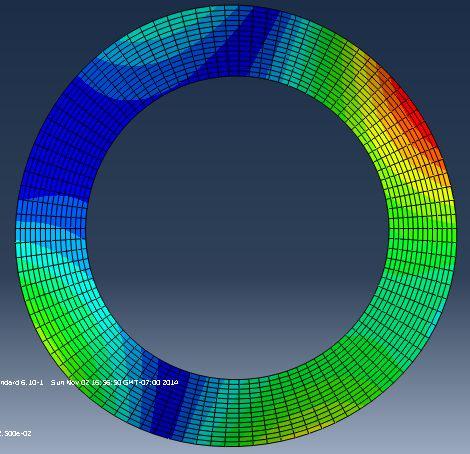
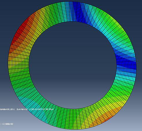
41 the radius and by the fact that the frictional heat generation rate is a linear function of the sliding speed. The sinusoidal distribution is related to the local high temperature regions known as hot spots that could be excited by thermoelastic instability. An exponential distribution can be caused by the non-uniform convective cooling on the plate surface or a non-uniform contact pressure during the engagement and separation of plates. Additionally, the temperature gradient may exist in both radial and circumferential directions. It is possible that the temperature patterns have some effects on the thermal buckling mode and the buckling temperatures, so we choose various temperature patterns and compute the eigenvalues of thermal buckling. To obtain a more accurate result, we use the parameters from a realistic clutch that are shown in Table 3-4. Inner Outer Thickness Young s Poisson s Thermal Expansion Diameter Diameter Modulus Ratio Coefficient Di (mm) Do (mm) a (mm) E (GPa) ν α (K -1 ) Table 3-4: Geometric and material parameters of a realistic clutch plate Effect of monotonic temperature distribution along the radius Here we assume a temperature distribution monotonically changing from the inner to the outer radius. We investigate three different scenarios: r T 1 39 (15) T 39sin( ( R 0.086)) (16) 2 31
42 39(exp(60( R 0.086)) 1) T 3 (17) ( ) where T 1, T 2, T3 represent, respectively, linear, sinusoidal and exponential temperature distributions that are also illustrated in Figure 3-4. We chose the constants in these functions in such a way that all three functions have the same temperature difference of 39 C across the radius. Figure 3-4: Monotonic temperature profiles along radius The eigenvalues and the buckling temperatures computed by ABAQUS are shown in Table 3-5 and Figure 3-5. It is noticed that some of the eigenvalues and temperature gradients are negative, representing that the temperature decreases from the inner to outer radius. According to Table 3-5, the buckling temperature is typically very low for a monotonic temperature profile. The lowest buckling temperature is around 178 C, which is well below the maximum operating temperature of a clutch plate. 32
43 Eigenvalue Buckling temperature ( C) Mode Linear Sinusoidal Exponential Linear Sinusoidal Exponential Table 3-5: Eigenvalues and buckling temperatures of the monotonic radial temperature profiles Figure 3-5: Temperatures of the monotonic radial temperature profiles According to Figure 3-5, the temperature distribution pattern has a limited effect on the buckling temperature. As the buckling temperatures of Mode 1 and Mode 2 are the lowest, these two modes are the leading modes. This is consistent with the conclusions in 33

 Linear temperature")
")

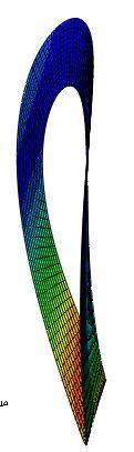
44 the previous researches. The first two buckling shapes of thermal distribution are shown in Figure 3-6. Mode 1 Mode 2 (a) Linear temperature distribution Mode 1 Mode 2 (b) Sinusoidal temperature distribution Mode 1 Mode 2 (c) Exponential temperature distribution Figure 3-6: Buckling modes of the monotonic radial temperature profiles 34
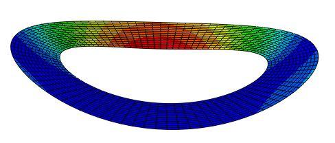
45 In Figure 3-6, the first two thermal buckling modes are always the axisymmetric mode (coning mode) and the non-axisymmetric mode (potato chip mode) in the condition that the temperature increases or decreases with the radius monotonically. Meanwhile, the coning mode can appear only if the temperature at the inner radius is the highest. In addition, it is obvious that the deformed shape changes with different thermal patterns. Therefore, we can conclude that the different thermal patterns that increase or decrease monotonically along the radius direction have significant effects on the deformed shape rather than the thermal buckling temperature Effect of non-monotonic temperature distribution along the radius To explore the phenomenon further, we assumed a different thermal profile pattern along the radius, in which the highest temperature is located at the mean radius, instead of the inner or outer radius. We made three different assumptions on the temperature distributions as expressed in the following functions, 78( r 0.086) ( r 0.086) T r (18) r T 39sin( ( R 0.086)) (19) 5 39(exp(120( R 0.086)) 1) ( ) 39(exp(120( R 0.125)) 1) ( ) T r r (20) where T 4, T 5, T6 are, respectively, linear, sinusoidal and exponential temperature distributions that are shown in Figure


46 Figure 3-7: Non-monotonic radial temperature profiles We chose the constants in these functions in such a way that all three functions have the same temperature difference of 39 C between the inner and the mean radii, which is consistent with the previous case of monotonic distribution. We follow the same procedure to perform the finite element analysis. The obtained eigenvalues and buckling temperatures are shown in Table 3-6 and Figure
47 Eigenvalue Buckling temperature ( C) Mode Linear Sinusoidal Exponential Linear Sinusoidal Exponential Table 3-6: Eigenvalues and buckling temperatures of the non-monotonic radial temperature profiles Figure 3-8: Temperatures of the non-monotonic radial temperature profiles According to Figure 3-8, when the highest temperature is located at the mean radius, the effect of thermal patterns on the critical buckling temperature is insignificant. Compared to Tables 3-5 and 3-6, it is clear that the eigenvalues of this case are much larger than those under monotonic temperature distributions. For example, when the 37
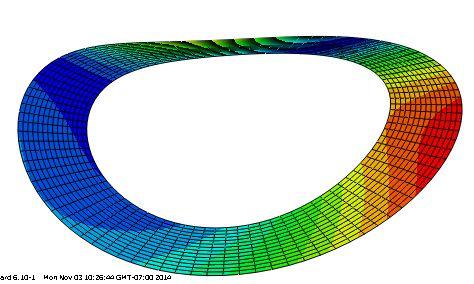
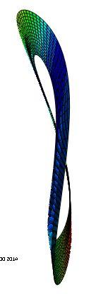
48 temperature distribution is a piecewise linear function, the eigenvalue of Mode 1 here is approximately 10 times greater than that of monotonic temperature profile. In terms of the buckling temperature, we have found that the difference is close to 16 times, which is even greater. In fact, the typical value of the buckling temperature for non-monotonic temperature profiles is well above the operating temperatures of automotive clutches. Hence thermal buckling is more probable to take place under monotonic radial temperature profiles as opposed to non-monotonic temperature distributions. We also investigated the deformed shapes of the first two dominant modes that have the lowest buckling eigenvalues, as shown in Figure 3-9. In the figure it is clear that Mode 1 of all three thermal patterns has a potato chip shape and Mode 2 is a higher order one with more waves in the circumference. Meanwhile, the buckling shape varies with different thermal patterns. Consequently, we can conclude that the shape of the thermal pattern mainly affects the deformed shape rather than the buckling temperature. Finally, the axisymmetric coning mode cannot take place in a condition that the highest temperature is located in the middle of the radius. 38


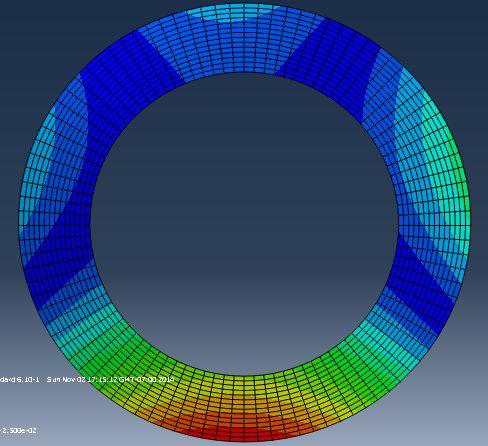
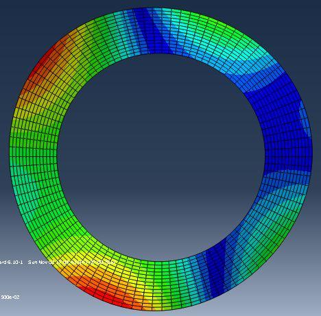
49 Mode 1 Mode 2 (a) Linear Mode 1 Mode 2 (b) Sinusoidal Mode 1 Mode 2 (c) Exponential Figure 3-9: Buckling modes of the non-monotonic radial temperature profiles 39
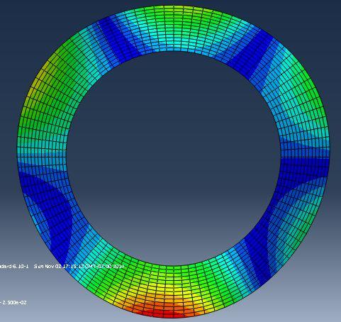
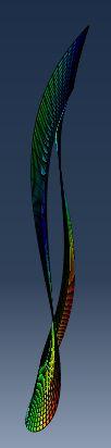
50 3.3.5 Effect of circumferential temperature distribution The temperature gradient may also exist in the circumferential direction. Here we assume a sinusoidal thermal distribution that has the same maximum temperature difference in the following form: T 39sin( N ) N=0.5, 1, 1.5, 2 (21) 7 where θ and n represent, respectively, the angular position and the wave number. The buckling eigenvalues and temperatures computed from the finite element analysis are reported in Table 3-7. Eigenvalue Buckling temperature ( C) Mode n=0.5 n=0.8 n=1 n=1.2 n=1.5 n=0.5 n=0.8 n=1 n=1.2 n= Table 3-7: Eigenvalues and buckling temperatures of the sinusoidal temperature profile in the circumference According to the table, roughly speaking there is a trend in the buckling temperature to increase with the wave number. For example, the buckling temperature of mode 1 is 1785 C at n=1.5, and 1071 C at n=0.5. However, the relationship is not linear. For 40
51 example, it is noticed that the buckling temperature decreases slightly from n=0.5 to n=1, then increases from n=1 to n=1.5. In general the buckling temperature here is much higher than those of the monontonic radial profile. However, some values are still below 1000 C and this can come close to the vicinity of the maximum operating temperature in some extreme cases. The eigenvectors of the first two modes are shown in Figure

")
 n=1.")


52 Mode 1 Mode 2 (a) n=0.25 Mode 1 Mode 2 (b) n=0.5 Mode 1 Mode 2 (c) n=1.0 Figure 3-10: Dominant buckling modes of the sinusoidal temperature distributions along the circumference 42
53 For an integer wave number greater than 1, it is found that the structure will not buckle at any temperature. It can be explained by the fact that the material expands in the hot region and contracts in the cold region. These thermal effects will counteract each other and eventually cancel out, leading to an unconditional stable situation. Meanwhile, a temperature distribution of non-integer wave number may lead to buckling, although this scenario is not common in practical applications. 3.4 Conclusions In this chapter, the effects of different temperature distribution patterns are studied. It has been found that the coning mode only occurs when the temperature distribution is monotonic along radius. Also, the critical buckling temperature under this temperature pattern is the lowest. The type of the monotonic temperature distribution has limit effect on thermal buckling temperature. However, it affects the buckling shape. The non-monotonic temperature distribution shows a great resistance on thermal buckling due to the high critical buckling temperature. The results agree well with Timoshenko s beam theory. The circumferential temperature distribution is a rare pattern but shows a complicated result. When the wave number is integer, buckling will never happen due to the counteraction of the hot and cold material expansion. The negative values in the results indicate the contrary temperature distribution. For study convenience, the studies in the following chapters will ignore the effect. 43
54 It should be pointed out that the monotonic temperature distribution is the most realistic pattern due to the friction at the outer edge. Therefore, this temperature pattern has been used for further study. 44
55 CHAPTER FOUR: PARAMETRIC STUDY AND EFFECT OF TEMPERATURE DISTRIBUTION ALONG THE THICKNESS DIRECTION IN BRAKE DISCS In this chapter, a study on material properties has been performed. The temperature distribution in the thickness direction is investigated, meanwhile the temperature variation in the radial direction is assumed monotonic. The brake discs have been chosen to the study due to the relatively larger thickness comparing with the clutch discs. Also, uniform temperature distribution along the thickness direction may no longer valid for brakes. In this study, the brake disc is assumed to be fully covered by the brake pad, which enables the smooth temperature distribution along the radius. 4.1 The Effect of Material Properties Vehicles have been designed and manufactured with different velocity limits, loading capabilities and operating conditions. The design of the brake and clutch systems must be optimized to meet these requirements. It is essential to perform a parametric study on material properties to determine how these parameter variations affect the critical buckling temperature. In this chapter, C3D20R element has been used instead of shell elements due to the relatively large errors generated by the shell elements when the temperature along the 45
56 thickness direction varies, which will be discussed later in this chapter. Here we use the same material and geometric parameters as in Ma s research [40] for the purpose of comparison. These parameters are shown in Table The effect of Young s modulus A set of studies with various Young s modulus have been performed via finite element analysis. The coefficient of thermal expansion and Poisson s ratio remain constant. A linear reference temperature gradient is assumed along the radius direction as follows: r 0.08 T 250 (22) The value of Young s modulus changes linearly from 88GPa to 110GPa with an increment of 4.4GPa (5%), an overall increase of 25%. The mesh ( ) used in the finite element analysis is shown in Figure 4-1. This model is used through this chapter. Figure 4-1: Finite element model used in the study on material properties 46
57 The eigenvalues and the critical buckling temperatures computed by ABAQUS are reported in Table 4-1. ν=0.3 α= (K -1 ) E=88 E=92.4 E=96.8 E=101.2 E=105.6 E=110 (GPa) (GPa) (GPa) (GPa) (GPa) (GPa) Mode T( C) Mode T( C) Mode T( C) Table 4-1: Eigenvalue and buckling temperatures of different Young s modulus An interesting result is that the eigenvalue is independent of Young s modulus, which means that the thermal buckling in this case is independent of Young s modulus. Even when the modulus is set to a very small value, the result remains the same. We can prove it based on the following discussion. There is no existing equation in the literature that can be directly used to determine the thermal buckling temperature. A set of equations (Eqs.9~12) can be used to establish the relationship between the in-plate bending moment and the temperature load from the theory of thermoelasticity. This can be simply expressed as: 47
58 M ~ T (23) Another set of equations (Eqs.4~6) can be used to compute the critical buckling moment without thermal effects based on Timoshenko s buckling theory. Combining all these equations we obtain: M ~ M critical ~ T critical (24) Thus, from Timoshenko s theory we obtain the critical buckling moment. By applying this moment to Eq. (23) we can determine the critical buckling load (i.e. temperature). The critical buckling load is the product of eigenvalue and the reference temperature load in the finite element analysis: T (25) critical T reference Eq.(6) can be written as: M c * c E 2M Ro R R R o i i a 3 (26) By replacing the shear modulus G, where: Substituting Eq. (10) into Eq. (9) we obtain: E G (27) 2 1 M Et Ro Ri 2 r r Ri C1 C2 rtd T 1 (1 ) r 2 Ro Ri ( r ) dr 2 (28) In this equation, C1 and C2 are uncorrelated with E in both free and non-free boundary conditions. 48
59 By combining Eq. (26) and (28), the critical buckling load can be found. It has been found that Young s modulus disappears from the final result. Therefore the critical buckling load is independent of Young s modulus. This conclusion shows a good agreement with the finite element simulation. From the result, we can conclude that when single material is used, Young s modulus has no effect on thermal buckling, which may benefit the clutch/brake design in real applications. It should be noted that in this case only a single material is used. The result based on models with multiple materials would not be the same. The discussion on this problem will be made in Chapter 6. Also, Young s modulus does have effects on some mechanical problems other than thermal loads. The current study is based on the thermal effect only The effect of Poisson s ratio A set of studies with various value of Poisson s ratio have been performed via the finite element analysis. The coefficient of thermal expansion and Young s modulus remain constant. A linear reference temperature gradient is assumed along the radius direction as Eq. (22). Poisson s ratio changes linearly from 0.24 to 0.3 with an increment of (5%), an overall 25% increase. The eigenvalues and the critical buckling temperatures computed by ABAQUS are reported in Table 4-2 and Figure
60 E=110GPa a=1.25e-5k -1 V=0.24 V=0.252 V=0.264 V=0.276 V=0.288 V=0.3 Max T. Diff. Mode T( C) Mode T( C) Mode T( C) Table 4-2: Eigenvalues and buckling temperatures of different Poisson s ratios Figure 4-2: Buckling temperature variation of different Poisson s ratios 50
61 From Table 4-2 we can see that the critical buckling temperature increases almost linearly with an increasing Poisson s ratio for Mode1. This effect is opposite for Mode 2 and Mode 3. This is caused by the different values of N in Eq. (4), where N is the order of the mode. This variation induces the changing of * M c with different order of K, where K 1, which changes the expressions of ν related terms. 2 From Figure 4-2 we can see that the curves are almost flat. This means that the influence of Poisson s ratio on the buckling temperature is very small. The maximum temperature difference is only 1.65 C for Mode 1 in the specified Poisson s ratio region. Even for Mode 3, which rarely occurs in real applications (A test reported by Halderman [3] showed that the peak temperatures across the brake disc can reach 980 C.), the difference is 33.1 C, about 2.5% of the critical buckling temperature. This effect can be ignored as the range of Poisson s ratio, 0.24~0.3, is found in most materials. Therefore, we can conclude that the effect of Poisson s ratio is not significant in thermal buckling The effect of coefficient of thermal expansion A set of studies with various coefficients of thermal expansion have been performed via the finite element analysis. Poisson s ratio and Young s modulus remain constant. The temperature distribution keeps the same as the previous study. The coefficient of thermal expansion changes linearly from K -1 to K -1 by the increment of K -1 (5%), with an overall increase of 25%. 51
62 The eigenvalues and the critical buckling temperatures computed by ABAQUS are shown in Table 4-3 and Figure 4-3. E=110GPa ν=0.3 α=1 α=1.05 α=1.1 α=1.15 α=1.2 α=1.25 Max T (K -1 ) 10-5 (K -1 ) 10-5 (K -1 ) 10-5 (K -1 ) 10-5 (K -1 ) 10-5 (K -1 ) Diff. Mode T( C) Mode T( C) Mode T( C) Table 4-3: Eigenvalues and buckling temperatures of different coefficients of thermal expansion 52
63 Figure 4-3: Buckling temperature variation of different coefficients of thermal expansion According to Figure 4-3, the buckling temperature decreases almost linearly with the coefficient of thermal expansion. The decrement is significant, which shows the importance of thermal expansion in thermal buckling. The curve of Mode 3 has a larger slope than Modes 1 and 2 due to the effect of N in Eq. (4). All the modes show the monotonic decrease with the coefficient of thermal expansion. This can be validated and derived from Eq. (28), which can be simply expressed as: 1 T critical ~ (29) This validation also proves the accuracy and the feasibility of ABAQUS in the study on thermal buckling. From Table 4-3, the maximum temperature difference is C for Mode 1 in this study. This means that thermal expansion is the key factor in the 53
64 thermal buckling study. In practical applications, this material property must be measured carefully to make an accurate prediction on the thermal buckling load. 4.2 Effect of temperature distribution along the thickness direction Brake disc is a mechanical device which frequently suffers from contact friction. Often, each contact lasts several seconds. Within this time period, the heat generated is usually distributed non-uniformly along the thickness direction, even if the thickness is about 6mm. Thus, in thermal buckling study, a consideration of temperature distribution along the thickness direction is practical. The study on this effect can also be used to determine whether the thermal stress along the thickness direction is negligible. This will also benefit the further study on the model with friction layers D and 3-D elements comparison In the previous chapter, we have shown the accuracy and the efficiency of shell element (2-D). The temperature distribution is considered uniform along the thickness direction in that case. However, the study becomes a 3-D problem when temperature distribution along the thickness direction is assumed not uniform. Temperature now varies in r, θ, z directions in a cylindrical coordinate system. Therefore, a 3-D element is appropriate for this study. However, taking the consideration of computational efficiency, shell element is still a good choice if it shows a correct result. Thus, a comparison is performed between the shell element model and 3-D element model. 54
65 Shell element S4R and 3-D element C3D20R have been chosen in this study. The material properties and disc dimensions are shown in Table 3-1. A linear reference temperature gradient is assumed along the radius direction as Eq. (22). A linear temperature reduction by 20% is assumed along the thickness direction. The expression of the 3-D temperature field across the structure can be written as: r z T z (30) The temperature profile along thickness direction is shown in Figure 4-4. Figure 4-4: Linear temperature profile along the thickness direction In consideration of the change on the reference temperature load in this case (250 C at the friction surface and 200 C at the bottom, instead of constant 250 C in previous study), the computed critical buckling temperature cannot simply be the product of the 55
66 eigenvalue and 250 C as previous study. To figure out the new reference load, it is reasonable to assume the mean value of the temperature load along the thickness direction as the reference temperature load. By integrating the Eq. (30) with respect to z and taking the average, we can obtain: r 0.08 T 225 (31) The reference temperature load in Eq. (31) is now constant 225 C. Eq. (30) and (31) will be both used as the temperature fields in this simulation to perform the comparison. The mesh for S4R element model is , and for C3D30R element model. The computational results of both models are shown in Table 4-4 and Table 4-5 respectively. Shell element (S4R) Original Function Integrated Function Eigenvalue Critical Temp. Eigenvalue Critical Temp. Mode Mode Mode Table 4-4: Eigenvalues and buckling temperatures of the linear temperature profile along thickness direction by using shell element model 56
67 3-D element (C3D20R) Original Function Integrated Function Eigenvalue Critical Temp. Eigenvalue Critical Temp. Mode Mode Mode Table 4-5: Eigenvalues and buckling temperatures of the linear temperature profile along thickness direction by using 3-D element model According to Table 4-4, there is a significant difference in critical buckling temperatures between the results obtained from two different temperature fields by using shell element model. If the shell element is still suitable in this 3-D problem, we can have the following possible corollaries: 1. The simplified temperature distribution (Eq. 31) cannot displace the original 3-D temperature field (Eq. 30). 2. According to the data in the first group in Table 4-4, the critical buckling temperature of Mode 1 is 651 C. In consideration of the small stress along the thickness direction, the critical buckling temperature of Mode 1 should be near the result obtained from the model with uniform temperature distribution in the thickness direction ( C). However, the difference is 77 C which is very significant. Therefore, we 57
68 can also think that the reference temperature load (225 C) cannot simply be the mean value of the temperature load along the thickness direction. According to Table 4-5, we find that the eigenvalues in both groups are absolutely the same. This cannot be a coincident, which means that the simplified temperature field (Eq. 31) can substitute for the original one (Eq. 30). This result also negatives the corollaries 1 & 2. Thus, we can conclude that shell element is not appropriate in this 3-D case. One explanation is that the 3-D element model has a fixed origin of coordinates. The temperature field is established based on that coordinate. However, the shell element model does not have a clear coordinate corresponding relation along thickness direction due to the restriction of shell element itself. This causes the error in the simulation. Therefore, 3-D element model has been chosen in this study Effect of different temperature distribution patterns along thickness direction It should be noted that the computed critical buckling temperatures must be the same by using Eq. (22) and (31) as the reference temperature gradient due to the same temperature distribution pattern. Combing this conclusion and Table 4-5, we can obtain that the critical buckling temperatures computed by using Eq. (30) and (22) as the temperature fields are the same, which indicates that the temperature distribution along the thickness direction has no effect on thermal buckling. Three further studies are investigated to validate this conclusion. 58

69 A basic study is to check the mesh precision. Two models with different mesh densities are investigated in this study. One of the models has 3 elements along the thickness direction and the other one has 9. The element densities are shown in Figure 4-5. The other simulation settings keep the same with those in previous study. The results are shown in Table 4-6. Figure 4-5: Mesh densities along the thickness direction 3 elements 9 elements Eigenvalue Buckling Eigenvalue Buckling Temperature Temp. ( C) Temp. ( C) Difference Mode Mode Mode Table 4-6: Eigenvalues and buckling temperatures of mesh precision study along the thickness direction 59
70 According to Table 4-6, the temperature difference can be ignored, which means that the 3 elements along the thickness direction are sufficient for this study. This also proves that the thermal stress along the thickness direction can be ignored. In another study, the percentage of the linear temperature reduction along thickness direction becomes the variable. 10%, 30% and 40% reductions are assumed in this study. The expressions of the temperature fields are: T T T r z r z r z z (32) The temperature profiles are shown in Figure 4-6. Figure 4-6: Linear temperature profiles along the thickness direction 60
71 By integrating Eq. (32) with respect to z and taking the average value, we can obtain: T T T r r r (33) Eq. (32) and (33) will be both used as the temperature fields in this simulation to perform the comparison. The other settings keep the same with those in previous study. The results are shown in Table 4-7. Eigenvalue 10%reduction 30%reduction 40%reduction Original Integrated Original Integrated Original Integrated Mode Mode Mode Table 4-7: Eigenvalues of the study on different temperature reduction percentages along the thickness direction According to Table 4-7, we can see that the data in each group are absolutely the same, which validates that the simplified temperature field can substitute for the original one. Also, we have previously indicated that the critical buckling temperatures are the same with the same thermal load pattern, no matter what the values of the reference 61
72 temperature load are. Combining these two conclusions, we can conclude that the linear temperature distribution along thickness direction has no effect on thermal buckling. An exponential temperature distribution is assumed along the thickness direction in the third study. This distribution is possible because within a several seconds friction process, the temperature near the friction surface will be higher and decrease rapidly along the thickness direction. The temperature reduction is set to be 20%. The expression of the temperature field can be written as: r z T e (34) When z=0.006, r 0.08 T bottom 250 (35) When z=0, r 0.08 T bottom 200 (36) The shape of the temperature profile is shown in Figure
73 Figure 4-7: Exponential temperature profile along the thickness direction By integrating the equation with respect of z and taking the average value, we can obtain: r 0.08 T mean Tdz (37). Eq. (34) and (37) will be both used as the temperature fields in this simulation to make the comparison. The other settings keep the same with those in previous study. The results are shown in Table
74 Original Integrated Temp. Diff. Eigenvalue Temperature Eigenvalue Temperature Mode Mode Mode Table 4-8: Eigenvalues and buckling temperatures of exponential temperature profile along the thickness direction From Table 4-8 we can see that the eigenvalues in both groups are almost the same, which indicates that the exponential temperature profile along the thickness direction also has no effect on thermal buckling. The tiny difference is caused by taking approximations in the integration process. 4.3 Conclusion From the studies in this chapter, we can conclude that the possible patterns of temperature distribution along the thickness direction have very small or no effect on thermal buckling. The thermal stress along the thickness direction can be ignored. Temperature distribution along the radial direction is the dominant factor to induce thermal buckling. The thermal stress or the temperature distribution along the thickness direction in brake and clutch discs is always considered negligible. This study has validated that assumption via finite element method. This result will benefit the further study. Without 64
75 taking the consideration of temperature variation along the thickness direction, the computational efficiency and simplification can be obtained. 65
76 CHAPTER FIVE: THERMAL BUCKLING STUDY ON DISCS WITH A MANUFACTURED CONE ANGLE The friction discs may have a slight deformation after using for a time period due to the thermal and physical problems. Sometimes, the friction discs are manufactured with a small cone angle. The manufactured cone angle will help in that situation by having a better contact surface. This non-flat geometry may have effect on thermal buckling. A study on this effect has been performed in this chapter. 5.1 Effect of Different Manufactured Cone Angles on Thermal Buckling This chapter is devoted to studying the effect of different manufactured cone angles on thermal buckling. In this study, linear monotonic temperature distribution along the radial direction has been chosen as the reference temperature gradient due to the simple function and computational efficiency Study on the effect by using 3-D element model A set of studies with various cone angles have been performed via finite element analysis. The schematic of the disc and the finite element model are shown in Figure 5-1 and Figure 5-2. The geometry dimensions and material properties are shown in Table
. The mesh used in this model is 6 10 100. The element type is C3D20R. The cone angle varies from 1 to 5 by the increment of 1.")
77 Figure 5-1: The schematic of a brake disc with a cone angle Figure 5-2: The finite element model of a brake disc with a cone angle A linear reference temperature gradient is assumed along the radius direction as Eq. (22). The mesh used in this model is The element type is C3D20R. The cone angle varies from 1 to 5 by the increment of 1. The thermal buckling simulation results are shown in Table 5-1 and Figure
78 Eigenvalue Angle Mode Mode Mode Buckling Temperature ( C) Mode Mode Mode Table 5-1: Eigenvalues and buckling temperatures of different cone angle models obtained by using 3-D element model Figure 5-3: Buckling temperature variations of different cone angle models 68


 Cone angle 1 ~2 Mode 1 Mode")


79 From Table 5-1, we can find that the critical buckling temperature increases significantly with the increase of the cone angle for all modes. In Figure 5-3, the buckling temperature variation curves are almost linear for Mode 1 and 3. However, Mode 1 has the prior study significance than the others because it occurs first and has the lowest critical buckling temperature. The dominant buckling modes are shown in Figure 5-4. Mode 1 Mode 2 (a) Cone angle 1 ~2 Mode 1 Mode 2 (b) Cone angle 3 ~5 Figure 5-4: Dominant buckling modes of different cone angle models According to Figure 5-4, we find that for 1 ~2 cone angle models, the coning modes occur first, which agrees the conclusion in chapter 3 (For a linear profile of temperature, the axisymmetric coning mode occurs first). However, for 3 ~5 cone angle 69

80 models, the potato chip modes occur first, which shows a disagreement with the previous conclusion. According to Table 5-1, the critical buckling temperature difference between 1 and 5 cone angle models for Mode 1 is about 400 C. The result indicates that the manufactured cone angle improves the thermal buckling temperature significantly. A study by using axisymmetric element model has been performed to validate this conclusion Validation on the conclusion by using axisymmetric element model The axisymmetric element takes the advantage of the axisymmetric deformation. Thus, only the coning mode can be performed by axisymmetric element. However, this introduces an indirect validation by comparing the axisymmetric modes between the results obtained from 3-D and axisymmetric element models. The axisymmetric element CAX8R has been chosen in this study. The axisymmetric element model is shown in Figure 5-5. Figure 5-5: Axisymmetric element model of manufactured cone angle discs 70
81 The simulation settings keep the same with previous study. The result is shown in Table 5-2. CAX8R Mode C3D20R Mode Mode Mode Table 5-2: Eigenvalues of different cone angle models obtained by using axisymmetric element model According to Table 5-2, the eigenvalues obtained by using axisymmetric element model totally match the boldface data obtained by using 3-D element model. It should be noted that the axisymmetric element model can only perform the axisymmetric modes, which means that the modes of boldface data in Table 5-2 are axisymmetric. Therefore, we can indicate that Mode 1 is axisymmetric for 1 and 2 cone angle models and Mode 2 is axisymmetric for 3~5 cone angle models. This also infers that Mode 1 of 3~5 models is not axisymmetric, which agrees well with the result in last section. This study validates that the cone angle can improve the critical buckling temperature significantly. 71
82 One of the possible explanations for the result is that the first buckling mode of the flat disc is coning mode for the linear temperature distribution. This deformed mode has its own specific cone angle. We can name this angle θ1. On the other hand, the manufactured cone angle model can be considered as an initial conning model. We can name this cone angle θ2. When θ2 < θ1, the manufactured cone angle does not reach the level of the coning mode angle. The buckling Mode 1 for 1 and 2 cone angle models will be coning mode. When θ2 > θ1, the manufactured angle has already exceeded the coning mode angle. The buckling Mode 1 for 3~5 cone angle models will automatically jump over the conning mode to the potato chip mode. This buckling mode is shown in Figure 5-6. Based on beam buckling theory, for an inclined beam, it requires a larger external force along the beam direction to buckle than a non-inclined beam in order to have the same component force in buckling direction. Similarly, the cone angle model requires a larger thermal load to buckle than the flat model. In order to have the same component thermal stress, this thermal load will increase with the cone angle, which explains the buckling temperature variation in Figure 5-3. Also, with the same inner and outer radius, the cone angle models have a relatively larger volume and weight, which also improves the buckling temperature. 72

83 Figure 5-6: Buckling mode 1 for 3~5 cone angle models 5.2 Conclusion The results indicate that the manufactured cone angle improves the thermal buckling temperature significantly. For the simulation settings used in this study, a 5 cone angle model can withstand 1000 C, which is rarely in real applications. This study also indicates that the buckling modes are different for different cone angle models. For the disc used in this study, the critical point is between 2 and 3. The coning mode occurs first when the cone angle is below this threshold. Otherwise, the potato chip mode happens first. It should be noted that this study is devoted to thermal buckling research which means that other mechanical problems are not considered. The cone angle geometry may cause the non-uniform stress distribution induced by mechanical problems other than thermal load. These problems associated with vibration, inclined plane contact and etc. may cause structure instability. The current study is based on the thermal effect only. 73
84 CHAPTER SIX: FINITE ELEMENT ANALYSIS OF THERMAL BUCKLING IN CLUTCH DISCS WITH FRICITON LAYER AND NON-FREE BOUNDARY CONDITIONS Clutch discs are frequently subjected to friction between contact surfaces. In order to have better friction efficiency and less wearing, friction layers are applied to the surfaces of the discs. These layers are made of specific materials which have the entirely different properties comparing with the non-friction layer materials. No doubt the introduction of friction layers will influence thermal buckling. Also, the clutch discs are fixed by the teeth distributed around the outer edge in real applications. The non-free boundary condition should also be considered in thermal buckling study. This chapter has been performed to study these effects. 6.1 Effect of Friction Layer on Thermal Buckling Effect of different friction materials on thermal buckling under monotonic temperature distribution along the radial direction A set of studies with two different friction materials have been performed via the finite element analysis. The friction materials used in Lee and Barber s research [18], have been chosen in this study. The material of non-friction layer is assumed to be cast iron. 74
85 The properties of the materials used in friction layer and non-friction layer are shown in Table 6-1. Young s Modulus Poisson s Ratio Thermal Expansion E (GPa) ν α (10-5 K -1 ) Cast Iron Material A Material B Table 6-1: Material properties Material A is asbestos-based and B is semi-metallic material. The detailed geometry dimensions are shown in Table 6-2. The ABAQUS model is shown in Figure 6-1. Outer Diameter Inner Diameter Thickness Do (mm) Di (mm) t (mm) Friction layer Non-friction layer Table 6-2: Geometric dimensions 75
. Both friction materials A and B are investigated.")
86 Figure 6-1: ABAQUS clutch model with friction layer The mesh density for the friction layer is , and for the non-friction layer. A linear reference temperature gradient is assumed along the radius direction as Eq. (22). Both friction materials A and B are investigated. The eigenvalues and critical buckling temperatures are shown in Table 6-3 and Table 6-4, respectively. Friction Material A Without friction layer With friction layer Eigenvalue Temp. C Eigenvalue Temp. C T. Diff. C Mode Mode Mode Table 6-3: Eigenvalues and critical buckling temperatures for clutch disc by using material A as friction material 76
87 Friction Material B Without friction layer With friction layer Eigenvalue Temp. C Eigenvalue Temp. C T. Diff. C Mode Mode Mode Table 6-4: Eigenvalues and critical buckling temperatures for clutch disc by using material B as friction material According to Tables 6-3 and 6-4, the model with friction layer is easier to buckle under the same thermal load. The critical buckling temperature is quite lower comparing with the model without friction layer. For Mode 1, the critical buckling temperature difference is about 90 C which cannot be ignored. Therefore, it is essential to perform a study to determine how the friction layers affect the critical buckling temperature. Here is the explanation for the critical buckling temperature difference. Although Young s modulus has no effect on critical buckling temperature, it does affect the critical buckling moment. Comparing with non-friction layer, the friction layer has a relatively small critical buckling moment due to the smaller Young s modulus and the thinner thickness. These buckling moments can be computed from Eq. (6). In consideration of the interaction between two material layers, the critical buckling moment of the whole structure must be higher than that of friction layer. However, it must be lower than the 77
88 critical buckling moment without the introduction of friction layer. This finally reduces the critical buckling temperature. Comparing Tables 6-3 and 6-4, the critical buckling temperatures of both models are almost the same. Even the coefficients of thermal expansion of two friction materials are totally different. From Table 6-1, we can see that the Material A and B both have a very small Young s modulus comparing with cast iron. From the previous study, we have proved that thermal buckling is independent of Young's modulus when single material is applied. Thus, we can speculate that Young s modulus ratio between cast iron and friction material plays an important role in this study. For study efficiency, only Material A has been chosen in further studies. An individual study has been performed to determine how the value of Young s modulus affects the buckling temperature. Instead of 110GPa and 0.53GPa set in previous study, 110Pa and 0.53Pa are set as the new Young s modulus to perform the same study in the last section. The simulation result is absolutely the same as those in Table 6-3, which validates that the value of Young s modulus has no effect on thermal buckling. A set of simulations have been performed to study the effect of Young s modulus ratio. Eight Young s modulus ratios, 1:1, 2:1, 4:1, 8:1, 16:1, 32:1, 64:1 and 128:1 (Young s modulus of cast iron: Young s modulus of friction material) are assumed to in this study. The other simulation settings keep the same with previous study. The results are shown in Table 6-5 and Figure
89 Young s modulus ratios (Cast iron: friction material) 1:1 2:1 4:1 8:1 16:1 32:1 64:1 128:1 Mode Mode Mode Critical Buckling Temperature ( C) Mode Mode Mode Table 6-5: Eigenvalues and Buckling Temperatures of Young s modulus ratio study Figure 6-2: Effect of Young s modulus ratio on thermal buckling 79
90 According to Figure 6-2, the buckling temperature variation curves show an exponential decrease. This result indicates that there exists a complicated interaction between two material layers. From Table 6-5, we can find that the critical buckling temperature decreases rapidly with the increase of Young s modulus ratio at the initial and finally converges to about 483 C for Mode 1 in this case. The Young s modulus ratios for Material A and Material B are 207 and 110. At these ratio points, the curve has already converged. This well explains why the critical buckling temperatures of both models are almost the same in last section Effect of different friction layer thickness on thermal buckling under monotonic temperature distribution along the radial direction The variation of the thickness of friction layer will no doubt affect the critical buckling temperature. In this section, a set of studies have been performed via finite element method to determine how the thickness of friction layer affects the critical buckling temperature. In this study, the thickness of friction layer ranges from 0.4mm to 0.8mm. The total thickness of the disc remains 6mm. Material A has been chosen as the friction material. The temperature distribution keeps monotonic as Eq. (22). The results are shown in Table 6-6 and Figure
91 Eigenvalue Thickness 0.4mm 0.5mm 0.6mm 0.7mm 0.8mm Mode Mode Mode Critical buckling temperature ( C) Mode Mode Mode Table 6-6: Eigenvalues and buckling temperatures of clutch disc with different thickness friction layers Figure 6-3: Buckling temperature variation of clutch disc with different thickness friction layers 81
92 According to Figure 6-3, the buckling temperature variation curves show a linear decrease with the increase of thickness of friction layer for each mode. From Table 6-6, we can find that the maximum buckling temperature difference is about 69 C for Mode 1 in this case. The relationship of buckling temperature and the thickness of friction layer for Mode 1 can be fitted into following function: T 171.4t (38) When t=0, which means that the disc is only made of cast iron, the buckling temperature is about 570 C, which agrees well with previous study in the same condition (574 C). However, the Eq. (38) also indicates that the buckling temperature could be negative with a large t. Thus, another study has been performed to find the answer. In this study, the thickness of friction layer is set to be 6mm, which means that the disc is now only made of Material A. The other settings keep unchanged. The simulation result is shown in Table 6-7. t=6mm Mode1 Mode 2 Mode3 Eigenvalue Temperature ( C) Table 6-7: Eigenvalues and buckling temperatures of clutch disc made of material A According to Table 6-7, we can obtain that the critical buckling temperature is C for Mode 1. If we substitute t=6mm into Eq. (38), the answer is C which 82
93 is totally different from C. This result indicates that the entire red curve in Figure 6-3 is not simply linear. However, we do not need to care about the whole curve of the buckling temperature variation, because the thickness of friction layer is normally around 0.7mm and the clutch discs mainly consist of non-friction material. Therefore, we can conclude that the critical buckling temperature decreases linearly with the increase of the thickness of friction layer in this case Effect of temperature distribution along the thickness direction on thermal buckling of clutch discs with friction layer The previous study in chapter 4 has proved that when single material is applied, the temperature distribution along the thickness direction has no effect on thermal buckling. For the discs with friction layer, the higher temperature will be distributed on the surface of friction layer and the lower temperature will occur at the bottom of the non-friction layer. With multiple materials applied, the temperature distribution along the thickness direction may affect the critical buckling temperature. In the following study, the thickness of friction layer is set to be 0.5mm. Material A has been chosen as the friction material. A monotonic temperature gradient is assumed along the radial direction as Eq. (22). A linear temperature reduction by 10% to 40% is assumed along the thickness direction. The expressions of the 3-D temperature fields are same as Eq. (32). The other settings remain the same with the previous study. The results are shown in Table 6-8 and Figure 6-4. In previous study, we have already proved that the 83
94 reference temperature load for a 3-D temperature field is the mean temperature load along the thickness direction. Eigenvalue uniform 10% 20% 30% 40% Mode Mode Mode Temperature ( C) uniform 10% 20% 30% 40% Mode Mode Mode Table 6-8: Eigenvalues and buckling temperatures of clutch disc with friction layer under linear temperature distribution along thickness direction 84

95 Figure 6-4: Buckling temperature variation of clutch disc with friction layer under linear temperature distribution along thickness direction According to Figure 6-4, we can find that the critical buckling temperature increases linearly for each mode in this case. This result is different from the conclusion obtained by using the single material model. In Table 6-8, the maximum buckling temperature difference for Mode 1 is about 11 C which is small comparing with the critical buckling temperature. The effect of the temperature distribution along the thickness direction in this case is still not significant. 6.2 Effect of Non-Free Boundary Condition on Thermal Buckling In the literature of thermal buckling studies in discs, the boundary conditions were always assumed free-free. In real applications, the clutch discs are fixed by a number of teeth around the outer edge. One type of real clutch discs is shown in Figure 6-5. Figure 6-5: Clutch discs with teeth 85

96 An ABAQUS model is developed to study the effect of free-fixed boundary condition on thermal buckling. The tooth width is 40mm. The maximum diameter of the structure with teeth is 280mm. The rest geometry dimensions are shown in Table 6-2. The ABAQUS model is shown in Figure 6-6. The red part in the figure represents for the friction layer. Figure 6-6: ABAQUS model of clutch disc with teeth A set of studies have been performed via finite element method. Material A has been chosen in this study. The thickness of friction layer is 0.5mm. The reference temperature gradient is assumed as Eq. (22). The temperature distribution along the thickness direction is assumed uniform. The temperature field only covers the structure without teeth, which keeps the reference temperature load to be constant 250 C. The teeth are set free and fixed respectively in two groups of simulation for comparison. The results are shown in Table
97 Free teeth Fixed teeth Eigenvalue T ( C) Eigenvalue T ( C) Mode Mode Mode Table 6-9: Eigenvalues and buckling temperatures of clutch disc with teeth under non-free boundary condition Comparing Table 6-9 and Table 6-3, we can find that the model with teeth is harder to buckle comparing with the model without teeth under free-free boundary condition. The temperature difference is about 60 C for Mode 1. The explanation for the temperature difference is that the model with teeth has a larger volume and weight, which improves the critical buckling temperature. According to Table 6-9, the model under free-fixed boundary condition shows a great resistance to thermal buckling. The critical buckling temperature for Mode 1 is 1335 C which is rarely in real applications. The buckling modes of the model under free-free boundary condition are same with those in Figure 3-6 due to the same thermal load pattern and boundary condition. The buckling modes for the model under free-fixed boundary condition are shown in Figure


98 Mode 1 Mode 2 Figure 6-7: Dominant buckling modes of clutch disc under free-fixed boundary condition According to Figure 6-7, the buckling Mode 1 of the model under free-fixed boundary condition still can be considered as a coning mode though it is not a perfect coning mode due to the fixed boundary. Mode 2 is a potato chip mode which is almost the same as Mode 2 in Figure 3-6. Therefore, we can conclude that the free-fixed 88
Finite Element Analysis of Thermomechanical Processes in Disk Clutch Systems
 University of Denver Digital Commons @ DU Electronic Theses and Dissertations Graduate Studies 1-1-2013 Finite Element Analysis of Thermomechanical Processes in Disk Clutch Systems Zhuo Chen University
Transient Analysis of Disk Brake By using Ansys Software
 Transient Analysis of Disk Brake By using Ansys Software G. Babukanth & M. Vimal Teja Department of Mechanical Engineering, Nimra College of Engineering & Technology, Ibrahimpatnam, Vijayawada E-mail :
NUMERICAL INVESTIGATION OF A THREE-DIMENSIONAL DISC-PAD MODEL WITH AND WITHOUT THERMAL EFFECTS
 THERMAL SCIENCE: Year 2015, Vol. 19, No. 6, pp. 2195-2204 2195 NUMERICAL INVESTIGATION OF A THREE-DIMENSIONAL DISC-PAD MODEL WITH AND WITHOUT THERMAL EFFECTS by Ali BELHOCINE * Faculty of Mechanical Engineering,
International Journal of Scientific & Engineering Research, Volume 7, Issue 4, April ISSN STRUCTURAL ANALYSIS OF DUAL BRAKE SYSTEM
 International Journal of Scientific & Engineering Research, Volume 7, Issue 4, April-2016 71 STRUCTURAL ANALYSIS OF DUAL BRAKE SYSTEM Yuvaperiyasamy M 1, Kailasam R 2, Premkumar R 3 Vinothkumar S 4 Assistant
Study Effect of Pads shapes on Temperature Distribution for Disc Brake Contact Surface
 International Journal of Engineering Research and Development e-issn: 2278-067X, p-issn: 2278-800X, www.ijerd.com Volume 8, Issue 9 (September 2013), PP. 62-67 Study Effect of Pads shapes on Temperature
Generic Strategies to Implement Material Grading in Finite Element Methods for Isotropic and Anisotropic Materials
 University of Nebraska - Lincoln DigitalCommons@University of Nebraska - Lincoln Engineering Mechanics Dissertations & Theses Mechanical & Materials Engineering, Department of Winter 12-9-2011 Generic
PES Institute of Technology
 PES Institute of Technology Bangalore south campus, Bangalore-5460100 Department of Mechanical Engineering Faculty name : Madhu M Date: 29/06/2012 SEM : 3 rd A SEC Subject : MECHANICS OF MATERIALS Subject
Thermomechanical Stabilities in Automotive Brakes & Clutches Systems
 University of Denver Digital Commons @ DU Electronic Theses and Dissertations Graduate Studies 1-1-2015 Thermomechanical Stabilities in Automotive Brakes & Clutches Systems Ali Bendawi University of Denver
Tushar R Banode, S B Patil. Abstract
 International Engineering Research Journal Experimental stress, Thermal analysis and Topology optimization of Disc brake using strain gauging technique and FEA Tushar R Banode, S B Patil Mechanical EngineeringDepartment,
Stress and Temperature Distribution Study in a Functionally Graded Brake Disk
 Stress and Temperature Distribution Study in a Functionally Graded Brake Disk P. Hosseini Tehrani, M.Talebi2 Assistant professor, 2 MS c. Student, Center of excellence in railway transportation, School
ANALYSIS OF FRICTION BRAKES
 CHAPTER III ANALYSIS OF FRICTION BRAKES This chapter gives a brief account of all the governing equations and brake design parameters. These governing equations and design parameters are discussed with
CFD Analysis and Comparison of Different Ventilation Geometries for Brake Discs
 CFD Analysis and Comparison of Different Ventilation Geometries for Brake Discs Vijay Gautam DTU, Delhi, India 110042 vijaygautam@dce.ac.in Ananya Bhardwaj DTU, Delhi, India 110042 ananyabhardwaj22@gmail.com
Thermo-mechanical Investigation of Ventilated Disc Brake with Finite Element Analysis
 Thermo-mechanical Investigation of Ventilated Disc Brake with Finite Element Analysis Arifin #1, Mohammad Tauviqirrahman #2, Muchammad *3, J. Jamari #, A.P. Bayuseno # # Laboratory for Engineering Design
THERMAL BEHAVIOR OF DOUBLE ARC GROOVE FRICTION PAIRS IN HYDRO- VISCOUS DRIVE UNDER SOFT START-UP CONDITION
 THERMAL BEHAVIOR OF DOUBLE ARC GROOVE FRICTION PAIRS IN HYDRO- VISCOUS DRIVE UNDER SOFT START-UP CONDITION Qiliang WANG 1,, Hongwei CUI 1,2*, Zisheng LIAN 1,2, Long LI 1, 1 College of Mechanical Engineering,
New Representation of Bearings in LS-DYNA
 13 th International LS-DYNA Users Conference Session: Aerospace New Representation of Bearings in LS-DYNA Kelly S. Carney Samuel A. Howard NASA Glenn Research Center, Cleveland, OH 44135 Brad A. Miller
A Study on the Tube of Integral Propeller Shaft for the Rear-wheel Drive Automobile Using Carbon Composite Fiber
 A Study on the Tube of Integral Propeller Shaft for the Rear-wheel Drive Automobile Using Carbon Composite Fiber Kibong Han Mechatronics Department, Jungwon University, 85 Munmu-ro, Goesan-gun, South Korea.
OPTIMAL DESIGN OF CLUTCH PLATE BASED ON HEAT AND STRUCTURAL PARAMETERS USING CFD AND FEA
 International Journal of Mechanical Engineering and Technology (IJMET) Volume 9, Issue 5, May 2018, pp. 717 724, Article ID: IJMET_09_05_079 Available online at http://www.iaeme.com/ijmet/issues.asp?jtype=ijmet&vtype=9&itype=5
PERIYAR CENTENARY POLYTECHNIC COLLEGE PERIYAR NAGAR - VALLAM THANJAVUR. DEPARTMENT OF MECHANICAL ENGINEERING QUESTION BANK
 PERIYAR CENTENARY POLYTECHNIC COLLEGE PERIYAR NAGAR - VALLAM - 613 403 - THANJAVUR. DEPARTMENT OF MECHANICAL ENGINEERING QUESTION BANK Sub : Strength of Materials Year / Sem: II / III Sub Code : MEB 310
FEA A Guide to Good Practice. What to expect when you re expecting FEA A guide to good practice
 FEA A Guide to Good Practice What to expect when you re expecting FEA A guide to good practice 1. Background Finite Element Analysis (FEA) has transformed design procedures for engineers. Allowing more
Members Subjected to Torsional Loads
 Members Subjected to Torsional Loads Torsion of circular shafts Definition of Torsion: Consider a shaft rigidly clamped at one end and twisted at the other end by a torque T = F.d applied in a plane perpendicular
Influence of residual stresses in the structural behavior of. tubular columns and arches. Nuno Rocha Cima Gomes
 October 2014 Influence of residual stresses in the structural behavior of Abstract tubular columns and arches Nuno Rocha Cima Gomes Instituto Superior Técnico, Universidade de Lisboa, Portugal Contact:
Tuesday, February 11, Chapter 3. Load and Stress Analysis. Dr. Mohammad Suliman Abuhaiba, PE
 1 Chapter 3 Load and Stress Analysis 2 Chapter Outline Equilibrium & Free-Body Diagrams Shear Force and Bending Moments in Beams Singularity Functions Stress Cartesian Stress Components Mohr s Circle for
Single Stop Transient Thermal Coupled with Structural Analysis and Repeated Braking Analysis with Convective Cooling for Ventilated Rotor
 Single Stop Transient Thermal Coupled with Structural Analysis and Repeated Braking Analysis with Convective Cooling for Ventilated Rotor Tirth Sodagar 1, Avadhoot Ahire 2 1Tirth Sodagar, Student, School
The Rotating Inhomogeneous Elastic Cylinders of. Variable-Thickness and Density
 Applied Mathematics & Information Sciences 23 2008, 237 257 An International Journal c 2008 Dixie W Publishing Corporation, U. S. A. The Rotating Inhomogeneous Elastic Cylinders of Variable-Thickness and
202 Index. failure, 26 field equation, 122 force, 1
 Index acceleration, 12, 161 admissible function, 155 admissible stress, 32 Airy's stress function, 122, 124 d'alembert's principle, 165, 167, 177 amplitude, 171 analogy, 76 anisotropic material, 20 aperiodic
Unit 18 Other Issues In Buckling/Structural Instability
 Unit 18 Other Issues In Buckling/Structural Instability Readings: Rivello Timoshenko Jones 14.3, 14.5, 14.6, 14.7 (read these at least, others at your leisure ) Ch. 15, Ch. 16 Theory of Elastic Stability
A numerical and experimental study on the factors that influence heat partitioning in disc brakes
 A numerical and experimental study on the factors that influence heat partitioning in disc brakes Item Type Conference paper Authors Loizou, Andreas; Qi, Hong Sheng; Day, Andrew J. Citation Loizou, A.,
Nonlinear Buckling Prediction in ANSYS. August 2009
 Nonlinear Buckling Prediction in ANSYS August 2009 Buckling Overview Prediction of buckling of engineering structures is a challenging problem for several reasons: A real structure contains imperfections
Temperature analysis of a pin-on-disc tribology test using experimental and numerical approaches
 Friction 4(2): 135 143 (2016) ISSN 2223-7690 DOI 10.1007/s40544-016-0110-1 CN 10-1237/TH RESEARCH ARTICLE Temperature analysis of a pin-on-disc tribology test using experimental and numerical approaches
STRESS STRAIN AND DEFORMATION OF SOLIDS, STATES OF STRESS
 1 UNIT I STRESS STRAIN AND DEFORMATION OF SOLIDS, STATES OF STRESS 1. Define: Stress When an external force acts on a body, it undergoes deformation. At the same time the body resists deformation. The
Mechanics of Materials II. Chapter III. A review of the fundamental formulation of stress, strain, and deflection
 Mechanics of Materials II Chapter III A review of the fundamental formulation of stress, strain, and deflection Outline Introduction Assumtions and limitations Axial loading Torsion of circular shafts
A Study of Annular Plate Buckling Problem with Tension Loaded at Inner Edge
 ANALELE UNIVERSITĂłII EFTIMIE MURGU REŞIłA ANUL XVII, NR. 1, 010, ISSN 1453-7397 Syed Noh, Mostafa Abdalla, Waleed Fekry Faris A Study of Annular Plate Buckling Problem with Tension Loaded at Inner Edge
COURSE TITLE : APPLIED MECHANICS & STRENGTH OF MATERIALS COURSE CODE : 4017 COURSE CATEGORY : A PERIODS/WEEK : 6 PERIODS/ SEMESTER : 108 CREDITS : 5
 COURSE TITLE : APPLIED MECHANICS & STRENGTH OF MATERIALS COURSE CODE : 4017 COURSE CATEGORY : A PERIODS/WEEK : 6 PERIODS/ SEMESTER : 108 CREDITS : 5 TIME SCHEDULE MODULE TOPICS PERIODS 1 Simple stresses
COURSE TITLE : THEORY OF STRUCTURES -I COURSE CODE : 3013 COURSE CATEGORY : B PERIODS/WEEK : 6 PERIODS/SEMESTER: 90 CREDITS : 6
 COURSE TITLE : THEORY OF STRUCTURES -I COURSE CODE : 0 COURSE CATEGORY : B PERIODS/WEEK : 6 PERIODS/SEMESTER: 90 CREDITS : 6 TIME SCHEDULE Module Topics Period Moment of forces Support reactions Centre
D : SOLID MECHANICS. Q. 1 Q. 9 carry one mark each.
 GTE 2016 Q. 1 Q. 9 carry one mark each. D : SOLID MECHNICS Q.1 single degree of freedom vibrating system has mass of 5 kg, stiffness of 500 N/m and damping coefficient of 100 N-s/m. To make the system
On Nonlinear Buckling and Collapse Analysis using Riks Method
 Visit the SIMULIA Resource Center for more customer examples. On Nonlinear Buckling and Collapse Analysis using Riks Method Mingxin Zhao, Ph.D. UOP, A Honeywell Company, 50 East Algonquin Road, Des Plaines,
MECHANICAL STRENGTH EXPERIMENTS OF CARBON/CARBON BRAKE DISK
 MECHANICAL STRENGTH EXPERIMENTS OF CARBON/CARBON BRAKE DISK Jae-seok Yoo 1, Dae-un Sung 1, Chun-Gon Kim 1,Chang-Sun Hong 1 and Kwang-Su Kim 2 1 Department of Aerospace Engineering, Korea Advanced Institute
Practice Final Examination. Please initial the statement below to show that you have read it
 EN175: Advanced Mechanics of Solids Practice Final Examination School of Engineering Brown University NAME: General Instructions No collaboration of any kind is permitted on this examination. You may use
Key words: Polymeric Composite Bearing, Clearance, FEM
 A study on the effect of the clearance on the contact stresses and kinematics of polymeric composite journal bearings under reciprocating sliding conditions Abstract The effect of the clearance on the
R13. II B. Tech I Semester Regular Examinations, Jan MECHANICS OF SOLIDS (Com. to ME, AME, AE, MTE) PART-A
 PART-A") SET - 1 II B. Tech I Semester Regular Examinations, Jan - 2015 MECHANICS OF SOLIDS (Com. to ME, AME, AE, MTE) Time: 3 hours Max. Marks: 70 Note: 1. Question Paper consists of two parts (Part-A and Part-B)
SET - 1 II B. Tech I Semester Regular Examinations, Jan - 2015 MECHANICS OF SOLIDS (Com. to ME, AME, AE, MTE) Time: 3 hours Max. Marks: 70 Note: 1. Question Paper consists of two parts (Part-A and Part-B)
Dynamic Response Of Laminated Composite Shells Subjected To Impulsive Loads
 IOSR Journal of Mechanical and Civil Engineering (IOSR-JMCE) e-issn: 2278-1684,p-ISSN: 2320-334X, Volume 14, Issue 3 Ver. I (May. - June. 2017), PP 108-123 www.iosrjournals.org Dynamic Response Of Laminated
CLUTCHES AND BRAKES. Square-jaw clutch
 Clutches: CLUTCHES AND BRAKES A Clutch is a mechanical device which is used to connect or disconnect the source of power from the remaining parts so the power transmission system at the will of the operator.
: APPLIED MECHANICS & STRENGTH OF MATERIALS COURSE CODE : 4021 COURSE CATEGORY : A PERIODS/ WEEK : 5 PERIODS/ SEMESTER : 75 CREDIT : 5 TIME SCHEDULE
 COURSE TITLE : APPLIED MECHANICS & STRENGTH OF MATERIALS COURSE CODE : 4021 COURSE CATEGORY : A PERIODS/ WEEK : 5 PERIODS/ SEMESTER : 75 CREDIT : 5 TIME SCHEDULE MODULE TOPIC PERIODS 1 Simple stresses
FREE VIBRATION ANALYSIS OF THIN CYLINDRICAL SHELLS SUBJECTED TO INTERNAL PRESSURE AND FINITE ELEMENT ANALYSIS
 FREE VIBRATION ANALYSIS OF THIN CYLINDRICAL SHELLS SUBJECTED TO INTERNAL PRESSURE AND FINITE ELEMENT ANALYSIS J. Kandasamy 1, M. Madhavi 2, N. Haritha 3 1 Corresponding author Department of Mechanical
Buckling Analysis of Isotropic Circular Plate with Attached Annular Piezoceramic Plate
 Malaysian Journal of Mathematical Sciences 10S February: 443 458 2016 Special Issue: The 3 rd International Conference on Mathematical Applications in Engineering 2014 ICMAE 14 MALAYSIAN JOURNAL OF MATHEMATICAL
High Tech High Top Hat Technicians. An Introduction to Solid Mechanics. Is that supposed to bend there?
 High Tech High Top Hat Technicians An Introduction to Solid Mechanics Or Is that supposed to bend there? Why don't we fall through the floor? The power of any Spring is in the same proportion with the
DHANALAKSHMI COLLEGE OF ENGINEERING, CHENNAI DEPARTMENT OF MECHANICAL ENGINEERING ME 6603 FINITE ELEMENT ANALYSIS PART A (2 MARKS)
") DHANALAKSHMI COLLEGE OF ENGINEERING, CHENNAI DEPARTMENT OF MECHANICAL ENGINEERING ME 6603 FINITE ELEMENT ANALYSIS UNIT I : FINITE ELEMENT FORMULATION OF BOUNDARY VALUE PART A (2 MARKS) 1. Write the types
DHANALAKSHMI COLLEGE OF ENGINEERING, CHENNAI DEPARTMENT OF MECHANICAL ENGINEERING ME 6603 FINITE ELEMENT ANALYSIS UNIT I : FINITE ELEMENT FORMULATION OF BOUNDARY VALUE PART A (2 MARKS) 1. Write the types
HELICAL BUCKLING OF DRILL-STRINGS
 HELICAL BUCKLING OF DRILL-STRINGS Marcin Kapitaniak 1,, Vahid Vaziri 1,, and Marian Wiercigroch 1 1 Centre for Applied Dynamics Research, School of Engineering, University of Aberdeen, Aberdeen, AB24 3UE,
4. Objectives of Research work
 4. Objectives of Research work 4.1 Objectives of Study: The design of bellows is challenging looking to varieties of applications and evaluation of stresses is further difficult to approximate due to its
Longitudinal buckling of slender pressurised tubes
 Fluid Structure Interaction VII 133 Longitudinal buckling of slender pressurised tubes S. Syngellakis Wesse Institute of Technology, UK Abstract This paper is concerned with Euler buckling of long slender
Influence of the filament winding process variables on the mechanical behavior of a composite pressure vessel
 Influence of the filament winding process variables on the mechanical behavior of a composite pressure vessel G. Vargas 1 & A. Miravete 2 1 Universidad Pontificia Bolivariana, Facultad de Ingeniería Mecánica,
Size Effects In the Crushing of Honeycomb Structures
 45th AIAA/ASME/ASCE/AHS/ASC Structures, Structural Dynamics & Materials Conference 19-22 April 2004, Palm Springs, California AIAA 2004-1640 Size Effects In the Crushing of Honeycomb Structures Erik C.
Mechanics of Materials Primer
 Mechanics of Materials rimer Notation: A = area (net = with holes, bearing = in contact, etc...) b = total width of material at a horizontal section d = diameter of a hole D = symbol for diameter E = modulus
CHAPTER 6 HEAT DISSIPATION AND TEMPERATURE DISTRIBUTION OF BRAKE LINER USING STEADY STATE ANALYSIS
 131 CHAPTER 6 HEAT DISSIPATION AND TEMPERATURE DISTRIBUTION OF BRAKE LINER USING STEADY STATE ANALYSIS 6.1 INTRODUCTION Drum brakes were the first types of brakes used on motor vehicles. Nowadays, over
Design against fluctuating load
 Design against fluctuating load In many applications, the force acting on the spring is not constants but varies in magnitude with time. The valve springs of automotive engine subjected to millions of
Mechanical Engineering Ph.D. Preliminary Qualifying Examination Solid Mechanics February 25, 2002
 student personal identification (ID) number on each sheet. Do not write your name on any sheet. #1. A homogeneous, isotropic, linear elastic bar has rectangular cross sectional area A, modulus of elasticity
Table of Contents. Preface...xvii. Part 1. Level
 Preface...xvii Part 1. Level 1... 1 Chapter 1. The Basics of Linear Elastic Behavior... 3 1.1. Cohesion forces... 4 1.2. The notion of stress... 6 1.2.1. Definition... 6 1.2.2. Graphical representation...
Using MATLAB and. Abaqus. Finite Element Analysis. Introduction to. Amar Khennane. Taylor & Francis Croup. Taylor & Francis Croup,
 Introduction to Finite Element Analysis Using MATLAB and Abaqus Amar Khennane Taylor & Francis Croup Boca Raton London New York CRC Press is an imprint of the Taylor & Francis Croup, an informa business
International Journal of Modern Trends in Engineering and Research e-issn No.: , Date: 2-4 July, 2015
 International Journal of Modern Trends in Engineering and Research www.ijmter.com e-issn No.:249-9745, Date: 2-4 July, 215 Thermal Post buckling Analysis of Functionally Graded Materials Cylindrical Shell
ARTICLE A-8000 STRESSES IN PERFORATED FLAT PLATES
 ARTICLE A-8000 STRESSES IN PERFORATED FLAT PLATES Delete endnote 18, which says "Express metric values in exponential form" A-8100 INTRODUCTION A-8110 SCOPE (a) This Article contains a method of analysis
Improving the Ability to Simulate Noise from Brake Squeal
 SIMULATE MORE ACCURATELY Improving the Ability to Simulate Noise from Brake Squeal Multidiscipline Simulation playing a key role in reducing brake squeal noise and vibration Brake Squeal Analysis Background
Study of coupling between bending and torsional vibration of cracked rotor system supported by radial active magnetic bearings
 Applied and Computational Mechanics 1 (2007) 427-436 Study of coupling between bending and torsional vibration of cracked rotor system supported by radial active magnetic bearings P. Ferfecki a, * a Center
Research on Heat Conduction Inverse Problem of Continuous Long Downhill Truck Brake
 International Conference on Civil, Transportation and Environment (ICCTE 2016) Research on Heat Conduction Inverse Problem of Continuous Long Downhill Truck Brake Shun Zeng1, a,heng Zhang2,b,Yunwei Meng1,c
Mechanical Principles
 Unit 4: Mechanical Principles Unit code: F/601/1450 QCF level: 5 Credit value: 15 Aim This unit aims to develop learners understanding of an extended range of mechanical principles that underpin the design
Chapter. Materials. 1.1 Notations Used in This Chapter
 Chapter 1 Materials 1.1 Notations Used in This Chapter A Area of concrete cross-section C s Constant depending on the type of curing C t Creep coefficient (C t = ε sp /ε i ) C u Ultimate creep coefficient
Mechanical Behavior of Circular Composite Springs with Extended Flat Contact Surfaces
 Mechanical Behavior of Circular Composite Springs with Extended Flat Contact Surfaces Ping-Cheung Tse epartment of Mechanical Engineering, The Hong Kong Polytechnic University, Hunghom, Kowloon, Hong Kong
KINGS COLLEGE OF ENGINEERING DEPARTMENT OF MECHANICAL ENGINEERING QUESTION BANK. Subject code/name: ME2254/STRENGTH OF MATERIALS Year/Sem:II / IV
 KINGS COLLEGE OF ENGINEERING DEPARTMENT OF MECHANICAL ENGINEERING QUESTION BANK Subject code/name: ME2254/STRENGTH OF MATERIALS Year/Sem:II / IV UNIT I STRESS, STRAIN DEFORMATION OF SOLIDS PART A (2 MARKS)
Computational Analysis for Composites
 Computational Analysis for Composites Professor Johann Sienz and Dr. Tony Murmu Swansea University July, 011 The topics covered include: OUTLINE Overview of composites and their applications Micromechanics
COPYRIGHTED MATERIAL. Index
 Index A Admissible function, 163 Amplification factor, 36 Amplitude, 1, 22 Amplitude-modulated carrier, 630 Amplitude ratio, 36 Antinodes, 612 Approximate analytical methods, 647 Assumed modes method,
Figure 43. Some common mechanical systems involving contact.
 33 Demonstration: experimental surface measurement ADE PhaseShift Whitelight Interferometer Surface measurement Surface characterization - Probability density function - Statistical analyses - Autocorrelation
Self-Excited Vibration
 Wenjing Ding Self-Excited Vibration Theory, Paradigms, and Research Methods With 228 figures Ö Springer Contents Chapter 1 Introduction 1 1.1 Main Features of Self-Excited Vibration 1 1.1.1 Natural Vibration
A RESEARCH ON NONLINEAR STABILITY AND FAILURE OF THIN- WALLED COMPOSITE COLUMNS WITH OPEN CROSS-SECTION
 A RESEARCH ON NONLINEAR STABILITY AND FAILURE OF THIN- WALLED COMPOSITE COLUMNS WITH OPEN CROSS-SECTION H. Debski a*, J. Bienias b, P. Jakubczak b a Faculty of Mechanical Engineering, Department of Machine
SIZE EFFECTS IN THE COMPRESSIVE CRUSHING OF HONEYCOMBS
 43rd AIAA/ASME/ASCE/AHS/ASC Structures, Structural Dynamics, and Materials Con 22-25 April 2002, Denver, Colorado SIZE EFFECTS IN THE COMPRESSIVE CRUSHING OF HONEYCOMBS Erik C. Mellquistand Anthony M.
A HIGHER-ORDER BEAM THEORY FOR COMPOSITE BOX BEAMS
 A HIGHER-ORDER BEAM THEORY FOR COMPOSITE BOX BEAMS A. Kroker, W. Becker TU Darmstadt, Department of Mechanical Engineering, Chair of Structural Mechanics Hochschulstr. 1, D-64289 Darmstadt, Germany kroker@mechanik.tu-darmstadt.de,
Thermo-Mechanical Analysis of Automotive Disc Brake Composite Rotor
 International Journal of Engineering Science Invention ISSN (Online): 2319 6734, ISSN (Print): 2319 6726 Volume 6 Issue 5 May 2017 PP. 40-48 Thermo-Mechanical Analysis of Automotive Disc Brake Composite
UNCONVENTIONAL FINITE ELEMENT MODELS FOR NONLINEAR ANALYSIS OF BEAMS AND PLATES
 UNCONVENTIONAL FINITE ELEMENT MODELS FOR NONLINEAR ANALYSIS OF BEAMS AND PLATES A Thesis by WOORAM KIM Submitted to the Office of Graduate Studies of Texas A&M University in partial fulfillment of the
ME Final Exam. PROBLEM NO. 4 Part A (2 points max.) M (x) y. z (neutral axis) beam cross-sec+on. 20 kip ft. 0.2 ft. 10 ft. 0.1 ft.
 M (x) y. z (neutral axis) beam cross-sec+on. 20 kip ft. 0.2 ft. 10 ft. 0.1 ft.") ME 323 - Final Exam Name December 15, 2015 Instructor (circle) PROEM NO. 4 Part A (2 points max.) Krousgrill 11:30AM-12:20PM Ghosh 2:30-3:20PM Gonzalez 12:30-1:20PM Zhao 4:30-5:20PM M (x) y 20 kip ft 0.2
ME 323 - Final Exam Name December 15, 2015 Instructor (circle) PROEM NO. 4 Part A (2 points max.) Krousgrill 11:30AM-12:20PM Ghosh 2:30-3:20PM Gonzalez 12:30-1:20PM Zhao 4:30-5:20PM M (x) y 20 kip ft 0.2
Finite Element Formulation for Prediction of Over-speed and burst-margin limits in Aero-engine disc
 International Journal of Soft Computing and Engineering (IJSCE) Finite Element Formulation for Prediction of Over-speed and burst-margin limits in Aero-engine disc Maruthi B H, M. Venkatarama Reddy, K.
MAAE 2202 A. Come to the PASS workshop with your mock exam complete. During the workshop you can work with other students to review your work.
 It is most beneficial to you to write this mock final exam UNDER EXAM CONDITIONS. This means: Complete the exam in 3 hours. Work on your own. Keep your textbook closed. Attempt every question. After the
DETERMINING THE STRESS PATTERN IN THE HH RAILROAD TIES DUE TO DYNAMIC LOADS 1
 PERIODICA POLYTECHNICA SER. CIV. ENG. VOL. 46, NO. 1, PP. 125 148 (2002) DETERMINING THE STRESS PATTERN IN THE HH RAILROAD TIES DUE TO DYNAMIC LOADS 1 Nándor LIEGNER Department of Highway and Railway Engineering
Stress analysis of functionally graded discs under mechanical and thermal loads
 Indian Journal of Engineering & Materials Sciences Vol. 8, April 0, pp. -8 Stress analysis of functionally graded discs under mechanical and thermal loads Hasan Çallioğlu, Metin Sayer* & Ersin Demir Department
KINK BAND FORMATION OF FIBER REINFORCED POLYMER (FRP)
") KINK BAND FORMATION OF FIBER REINFORCED POLYMER (FRP) 1 University of Science & Technology Beijing, China, niukm@ustb.edu.cn 2 Tsinghua University, Department of Engineering Mechanics, Beijing, China,
KINK BAND FORMATION OF FIBER REINFORCED POLYMER (FRP) 1 University of Science & Technology Beijing, China, niukm@ustb.edu.cn 2 Tsinghua University, Department of Engineering Mechanics, Beijing, China,
CE6306 STRENGTH OF MATERIALS TWO MARK QUESTIONS WITH ANSWERS ACADEMIC YEAR
 CE6306 STRENGTH OF MATERIALS TWO MARK QUESTIONS WITH ANSWERS ACADEMIC YEAR 2014-2015 UNIT - 1 STRESS, STRAIN AND DEFORMATION OF SOLIDS PART- A 1. Define tensile stress and tensile strain. The stress induced
Lecture 6 Friction. Friction Phenomena Types of Friction
 Lecture 6 Friction Tangential forces generated between contacting surfaces are called friction forces and occur to some degree in the interaction between all real surfaces. whenever a tendency exists for
COMPRESSIVE BEHAVIOR OF IMPACT DAMAGED COMPOSITE LAMINATES
 16 TH INTERNATIONAL CONFERENCE ON COMPOSITE MATERIALS COMPRESSIVE BEHAVIOR OF IMPACT DAMAGED COMPOSITE LAMINATES Hiroshi Suemasu*, Wataru Sasaki**, Yuuichiro Aoki***, Takashi Ishikawa**** *Department of
[7] Torsion. [7.1] Torsion. [7.2] Statically Indeterminate Torsion. [7] Torsion Page 1 of 21
![[7] Torsion. [7.1] Torsion. [7.2] Statically Indeterminate Torsion. [7] Torsion Page 1 of 21](/thumbs/88/115835122.jpg "[7] Torsion. [7.1] Torsion. [7.2] Statically Indeterminate Torsion. [7] Torsion Page 1 of 21") [7] Torsion Page 1 of 21 [7] Torsion [7.1] Torsion [7.2] Statically Indeterminate Torsion [7] Torsion Page 2 of 21 [7.1] Torsion SHEAR STRAIN DUE TO TORSION 1) A shaft with a circular cross section is
[7] Torsion Page 1 of 21 [7] Torsion [7.1] Torsion [7.2] Statically Indeterminate Torsion [7] Torsion Page 2 of 21 [7.1] Torsion SHEAR STRAIN DUE TO TORSION 1) A shaft with a circular cross section is
Analytical Strip Method for Thin Isotropic Cylindrical Shells
 IOSR Journal of Mechanical and Civil Engineering (IOSR-JMCE) e-issn: 2278-1684,p-ISSN: 2320-334X, Volume 14, Issue 4 Ver. III (Jul. Aug. 2017), PP 24-38 www.iosrjournals.org Analytical Strip Method for
Agricultural Science 1B Principles & Processes in Agriculture. Mike Wheatland
 Agricultural Science 1B Principles & Processes in Agriculture Mike Wheatland (m.wheatland@physics.usyd.edu.au) Outline - Lectures weeks 9-12 Chapter 6: Balance in nature - description of energy balance
Chapter 3. Load and Stress Analysis. Lecture Slides
 Lecture Slides Chapter 3 Load and Stress Analysis 2015 by McGraw Hill Education. This is proprietary material solely for authorized instructor use. Not authorized for sale or distribution in any manner.
Expansion of circular tubes by rigid tubes as impact energy absorbers: experimental and theoretical investigation
 Expansion of circular tubes by rigid tubes as impact energy absorbers: experimental and theoretical investigation M Shakeri, S Salehghaffari and R. Mirzaeifar Department of Mechanical Engineering, Amirkabir
BEAMS AND PLATES ANALYSIS
 BEAMS AND PLATES ANALYSIS Automotive body structure can be divided into two types: i. Frameworks constructed of beams ii. Panels Classical beam versus typical modern vehicle beam sections Assumptions:
UNIT 1 STRESS STRAIN AND DEFORMATION OF SOLIDS, STATES OF STRESS 1. Define stress. When an external force acts on a body, it undergoes deformation.
 UNIT 1 STRESS STRAIN AND DEFORMATION OF SOLIDS, STATES OF STRESS 1. Define stress. When an external force acts on a body, it undergoes deformation. At the same time the body resists deformation. The magnitude
Advanced Mechanical Principles
 Unit 36: Unit code Advanced Mechanical Principles R/615/1504 Unit level 5 Credit value 15 Introduction A mechanical engineer is required to have an advanced knowledge of most of the machinery used within
Large Thermal Deflections of a Simple Supported Beam with Temperature-Dependent Physical Properties
 Large Thermal Deflections of a Simple Supported Beam with Temperature-Dependent Physical Properties DR. ŞEREF DOĞUŞCAN AKBAŞ Civil Engineer, Şehit Muhtar Mah. Öğüt Sok. No:2/37, 34435 Beyoğlu- Istanbul,
Thermal buckling and post-buckling of laminated composite plates with. temperature dependent properties by an asymptotic numerical method
 hermal buckling and post-buckling of laminated composite plates with temperature dependent properties by an asymptotic numerical method F. Abdoun a,*, L. Azrar a,b, E.M. Daya c a LAMA, Higher School of
SRI CHANDRASEKHARENDRA SARASWATHI VISWA MAHAVIDHYALAYA
 SRI CHANDRASEKHARENDRA SARASWATHI VISWA MAHAVIDHYALAYA (Declared as Deemed-to-be University under Section 3 of the UGC Act, 1956, Vide notification No.F.9.9/92-U-3 dated 26 th May 1993 of the Govt. of
Self-weight loading of horizontal hydraulic cylinders with axial load
 Journal of Physics: Conference Series PAPER OPEN ACCESS Self-weight loading of horizontal hydraulic cylinders with axial load Related content - Stability analysis of large slenderness ratio horizontal
SECOND ENGINEER REG. III/2 APPLIED MECHANICS
 SECOND ENGINEER REG. III/2 APPLIED MECHANICS LIST OF TOPICS Static s Friction Kinematics Dynamics Machines Strength of Materials Hydrostatics Hydrodynamics A STATICS 1 Solves problems involving forces
Deflections and Strains in Cracked Shafts due to Rotating Loads: A Numerical and Experimental Analysis
 Rotating Machinery, 10(4): 283 291, 2004 Copyright c Taylor & Francis Inc. ISSN: 1023-621X print / 1542-3034 online DOI: 10.1080/10236210490447728 Deflections and Strains in Cracked Shafts due to Rotating
Esben Byskov. Elementary Continuum. Mechanics for Everyone. With Applications to Structural Mechanics. Springer
 Esben Byskov Elementary Continuum Mechanics for Everyone With Applications to Structural Mechanics Springer Contents Preface v Contents ix Introduction What Is Continuum Mechanics? "I Need Continuum Mechanics