Boole Algebra and Logic Series
|
|
|
- Ezra Osborne
- 6 years ago
- Views:
Transcription


1 S1 Teknik Telekomunikasi Fakultas Teknik Elektro oole lgebra and Logic Series 2016/2017 CLO1-Week2-asic Logic Operation and Logic Gate
2 Outline Understand the basic theory of oolean Understand the basic algebra law in oolean based on set theory Understand how to operate algebra law by using basic logic operation Knowing about asic Logic Gate to express asic Operation 2
3 oolean lgebra oolean algebra provides the operations and the rules for working with the set = {0, 1} Why only 0 and 1? oolean algebra is a mathematical system for the manipulation of variables that can have one of two values. In formal logic, these values are true and false. In digital systems, these values are on and off, 1 and 0, or high and low. 3

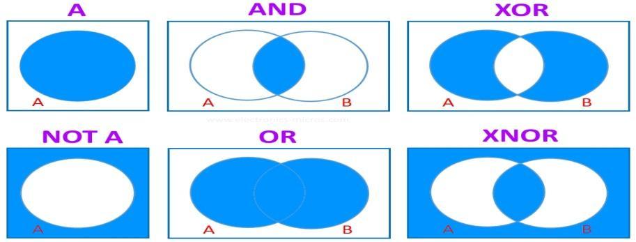
4 Operation Union / OR Set Operation - Union union is the set of all elements that are in, or, or both oolean Operation - OR The OR operator is the oolean sum Operator: + Logic Gate: Z S + 4

5 Operation Intersection / ND Set Operation - Intersect intersect is the set of all elements that are in both and. oolean Operation - ND The ND operator is also known as a oolean product Operator:. Logic Gate: Z S. 5

6 Operation Complement / NOT Set Operation - Complement complement, or not is the set of all elements not in S oolean Operation - NOT The NOT operation is most often designated by an overbar. It s also called inverter Operator: or Operator gate: Z 6
7 Operation Comp. Of Union / NOR Set Operation Is the complement of union S ( ) oolean Operator - NOR The NOR operation is combination of NOT and OR operation Operator : Logic Gate: Z + 7
8 Operation Comp. Of Intersect / NND Set Operation Is the complement of intersect S ( ). oolean Operation - NND The NND operation is combination of NOT and ND operation Operator : Logic Gate: Z 8
9 Operation Symmetric Differece / XOR Set Operation Sym. Diff. ( ) - ( ) S oolean Operation - XOR The output of the XOR operation is true only when the values of the inputs differ Operator: Logic Gate: Z 9
10 oolean Function oolean function has: t least one oolean variable, t least one oolean operator, and t least one input from the set {0,1}. It produces an output that is also a member of the set {0,1}. Now you know why the binary numbering system is so handy in digital systems Digital System is based on PULSE SIGNL, which valued 0 or 1 10


11 Combination in oolean Function Multiple Inputs? (>2 inputs) Multiple Inputs-Outputs? Multiple Gate/Operator? 11

12 Let s start from the simplest The three simplest gates are the ND, OR, and NOT gates. They correspond directly to their respective oolean operations, as you can see by their truth tables. 12

13 3.3 Logic Gates nother very useful gate is the exclusive OR (XOR) gate. The output of the XOR operation is true only when the values of the inputs differ. Note the special symbol for the XOR operation. 13

14 3.3 Logic Gates NND and NOR are two very important gates. Their symbols and truth tables are shown at the right. 14
15 ND and OR gate with 3 inputs C..C C ++C
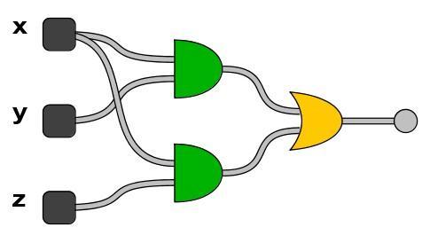
16 Example of Simple Series? 16
17 Truth table of the Series
18 Example in Implementation f f
19 Example in Implementation f f 19
20 Chips/ IC Digital Dasar To implement the logic diagram, we use the digital electronic series of logic IC/chips The kind of Logic Chip there are in market is IC TTL (Transistortransistor Logic) or MOS Those Chip are identified by part number or model number. IC type of standard digital series is started by number 74, 4, or is an inverter 7408 is an ND 7432 is an OR 4011 is a NND 20
21 Chips asic Logic Chip is in DIP form (dual in package) with even pins. The usual form has 14-pins Pin 1 marked by dot or halfcircle The next pin is read by CCW way Pin 14 Pin 8 Pin 1 Pin 7 21
22 Chips Chips need voltage to be operated Vcc is used to interface of 5 volts and VCC pin usually placed at last number of pins (for DIP14 so, VCC is at pin-14) Ground Pin usually placed at last pin at same side of first pin (for DIP14, so GND is at no.7) Voltage Ground 22
23 Example of asic Logic IC TTL 74LS00 : Quad 2 input NND Gate 74LS08 : Quad 2 input ND Gate VCC VCC GND GND 23
24 Example of asic Logic IC TTL 74LS02 : Quad 2 input NOR Gate 74LS32 : Quad 2 input OR Gate VCC VCC GND GND 24
25 Example of asic Logic IC TTL 74LS04 : Hex Inverter 74LS86 : Quad 2 input XOR Gate VCC VCC GND GND 25

26 3.3 Logic Gates NND and NOR are known as universal gates because they are inexpensive to manufacture and any oolean function can be constructed using only NND or only NOR gates. 26
27 3.3 Logic Gates Gates can have multiple inputs and more than one output. second output can be provided for the complement of the operation. We ll see more of this later. 27

28 3.4 Digital Components The main thing to remember is that combinations of gates implement oolean functions. The circuit below implements the oolean function: We simplify our oolean expressions so that we can create simpler circuits. 28
29 3.5 Combinational Circuits Combinational logic circuits give us many useful devices. One of the simplest is the half adder, which finds the sum of two bits. We can gain some insight as to the construction of a half adder by looking at its truth table, shown at the right. 29

30 3.5 Combinational Circuits s we see, the sum can be found using the XOR operation and the carry using the ND operation. 30
31 3.5 Combinational Circuits We can change our half adder into to a full adder by including gates for processing the carry bit. The truth table for a full adder is shown at the right. 31
32 3.5 Combinational Circuits How can we change the half adder shown below to make it a full adder? 32
33 3.5 Combinational Circuits Here s our completed full adder. 33
34 34
Digital Circuits. 1. Inputs & Outputs are quantized at two levels. 2. Binary arithmetic, only digits are 0 & 1. Position indicates power of 2.
 Digital Circuits 1. Inputs & Outputs are quantized at two levels. 2. inary arithmetic, only digits are 0 & 1. Position indicates power of 2. 11001 = 2 4 + 2 3 + 0 + 0 +2 0 16 + 8 + 0 + 0 + 1 = 25 Digital
Logic Gates and Boolean Algebra
 Logic Gates and oolean lgebra The ridge etween Symbolic Logic nd Electronic Digital Computing Compiled y: Muzammil hmad Khan mukhan@ssuet.edu.pk asic Logic Functions and or nand nor xor xnor not 2 Logic
Lecture 9: Digital Electronics
 Introduction: We can classify the building blocks of a circuit or system as being either analog or digital in nature. If we focus on voltage as the circuit parameter of interest: nalog: The voltage can
Digital- or Logic Circuits. Outline Logic Circuits. Logic Voltage Levels. Binary Representation
 Outline Logic ircuits Introduction Logic Systems TTL MOS Logic Gates NOT, OR, N NOR, NN, XOR Implementation oolean lgebra ombinatorial ircuits Multipleer emultipleer rithmetic ircuits Simplifying Logic
Digital Electronics. Delay Max. FF Rate Power/Gate High Low (ns) (MHz) (mw) (V) (V) Standard TTL (7400)
 (MHz) (mw) (V) (V) Standard TTL (7400)") P57/67 Lec9, P Digital Electronics Introduction: In electronics we can classify the building blocks of a circuit or system as being either analog or digital in nature. If we focus on voltage as the circuit
P57/67 Lec9, P Digital Electronics Introduction: In electronics we can classify the building blocks of a circuit or system as being either analog or digital in nature. If we focus on voltage as the circuit
Boolean Algebra. Boolean Variables, Functions. NOT operation. AND operation. AND operation (cont). OR operation
. OR operation") oolean lgebra asic mathematics for the study of logic design is oolean lgebra asic laws of oolean lgebra will be implemented as switching devices called logic gates. Networks of Logic gates allow us to
oolean lgebra asic mathematics for the study of logic design is oolean lgebra asic laws of oolean lgebra will be implemented as switching devices called logic gates. Networks of Logic gates allow us to
Prove that if not fat and not triangle necessarily means not green then green must be fat or triangle (or both).
.") hapter : oolean lgebra.) Definition of oolean lgebra The oolean algebra is named after George ool who developed this algebra (854) in order to analyze logical problems. n example to such problem is: Prove
hapter : oolean lgebra.) Definition of oolean lgebra The oolean algebra is named after George ool who developed this algebra (854) in order to analyze logical problems. n example to such problem is: Prove
New Students Day Activity
 Course: S ELECTRONICS New Students Day ctivity Introduction: In S Level Electronics you need to gain an understanding of the electronic circuits so that you can then start to design your own circuits like
Experiment 7: Magnitude comparators
 Module: Logic Design Lab Name:... University no:.. Group no: Lab Partner Name: Experiment 7: Magnitude comparators Mr. Mohamed El-Saied Objective: Realization of -bit comparator using logic gates. Realization
Lab 3 Revisited. Zener diodes IAP 2008 Lecture 4 1
 Lab 3 Revisited Zener diodes R C 6.091 IAP 2008 Lecture 4 1 Lab 3 Revisited +15 Voltage regulators 555 timers 270 1N758 0.1uf 5K pot V+ V- 2N2222 0.1uf V o. V CC V Vin s = 5 V Vc V c Vs 1 e t = RC Threshold
XI STANDARD [ COMPUTER SCIENCE ] 5 MARKS STUDY MATERIAL.
![XI STANDARD [ COMPUTER SCIENCE ] 5 MARKS STUDY MATERIAL.](/thumbs/81/84726747.jpg "XI STANDARD [ COMPUTER SCIENCE ] 5 MARKS STUDY MATERIAL.") 2017-18 XI STANDARD [ COMPUTER SCIENCE ] 5 MARKS STUDY MATERIAL HALF ADDER 1. The circuit that performs addition within the Arithmetic and Logic Unit of the CPU are called adders. 2. A unit that adds two
2017-18 XI STANDARD [ COMPUTER SCIENCE ] 5 MARKS STUDY MATERIAL HALF ADDER 1. The circuit that performs addition within the Arithmetic and Logic Unit of the CPU are called adders. 2. A unit that adds two
LOGIC GATES A Y=A+B. Logic symbol of OR gate B The Boolean expression of OR gate is Y = A + B, read as Y equals A 'OR' B.
 LOGIC GTS J-Physics INTRODUCTION : logic gate is a digital circuit which is based on certain logical relationship between the input and the output voltages of the circuit. The logic gates are built using
CHAPTER 3 LOGIC GATES & BOOLEAN ALGEBRA
 CHPTER 3 LOGIC GTES & OOLEN LGER C H P T E R O U T C O M E S Upon completion of this chapter, student should be able to: 1. Describe the basic logic gates operation 2. Construct the truth table for basic
Gates and Flip-Flops
 Gates and Flip-Flops Chris Kervick (11355511) With Evan Sheridan and Tom Power December 2012 On a scale of 1 to 10, how likely is it that this question is using binary?...4? What s a 4? Abstract The operation
Digital electronic systems are designed to process voltage signals which change quickly between two levels. Low time.
 DIGITL ELECTRONIC SYSTEMS Digital electronic systems are designed to process voltage signals which change quickly between two levels. High Voltage Low time Fig. 1 digital signal LOGIC GTES The TTL digital
Fundamentals of Digital Design
 Fundamentals of Digital Design Digital Radiation Measurement and Spectroscopy NE/RHP 537 1 Binary Number System The binary numeral system, or base-2 number system, is a numeral system that represents numeric
Binary addition (1-bit) P Q Y = P + Q Comments Carry = Carry = Carry = Carry = 1 P Q
 P Q Y = P + Q Comments Carry = Carry = Carry = Carry = 1 P Q") Digital Arithmetic In Chapter 2, we have discussed number systems such as binary, hexadecimal, decimal, and octal. We have also discussed sign representation techniques, for example, sign-bit representation
Digital Arithmetic In Chapter 2, we have discussed number systems such as binary, hexadecimal, decimal, and octal. We have also discussed sign representation techniques, for example, sign-bit representation
Why digital? Overview. Number Systems. Binary to Decimal conversion
 Why digital? Overview It has the following advantages over analog. It can be processed and transmitted efficiently and reliably. It can be stored and retrieved with greater accuracy. Noise level does not
Lecture 10: 09//25/03 A.R. Neureuther Version Date 09/14/03 EECS 42 Introduction to Digital Electronics Andrew R. Neureuther
 EECS 42 Intro. Digital Electronics Fall 23 Lecture : 9//25/3.R. Neureuther Version Date 9/4/3 EECS 42 Introduction to Digital Electronics ndrew R. Neureuther Lecture # Prof. King: asic Digital locks 2
Section 1A. Introduction & Basic Principles. Engineering Areas
 ection 1 Introduction & asic Principles Engineering Measurements Engineering reas Research & Development Process Control Fabrication Manufacturing ervice & Maintenance Engineering Measurements 1 2 Engineering
Boolean algebra. Examples of these individual laws of Boolean, rules and theorems for Boolean algebra are given in the following table.
 The Laws of Boolean Boolean algebra As well as the logic symbols 0 and 1 being used to represent a digital input or output, we can also use them as constants for a permanently Open or Closed circuit or
Chapter 2. Digital Logic Basics
 Chapter 2 Digital Logic Basics 1 2 Chapter 2 2 1 Implementation using NND gates: We can write the XOR logical expression B + B using double negation as B+ B = B+B = B B From this logical expression, we
Digital Logic (2) Boolean Algebra
 Boolean Algebra") Digital Logic (2) Boolean Algebra Boolean algebra is the mathematics of digital systems. It was developed in 1850 s by George Boole. We will use Boolean algebra to minimize logic expressions. Karnaugh
Digital Logic (2) Boolean Algebra Boolean algebra is the mathematics of digital systems. It was developed in 1850 s by George Boole. We will use Boolean algebra to minimize logic expressions. Karnaugh
Digital Fundamentals
 Digital Fundamentals Tenth Edition Floyd hapter 5 Modified by Yuttapong Jiraraksopakun Floyd, Digital Fundamentals, 10 th 2008 Pearson Education ENE, KMUTT ed 2009 2009 Pearson Education, Upper Saddle
NTE74LS181 Integrated Circuit TTL Arithmetic Logic Unit/Function Generator
 NTE74LS181 Integrated Circuit TTL Arithmetic Logic Unit/Function Generator Description: The NTE74LS181 is an arithmetic logic unit (ALU)/function generator in a 24 Lead DIP type package that has the complexity
CHAPTER1: Digital Logic Circuits Combination Circuits
 CS224: Computer Organization S.KHABET CHAPTER1: Digital Logic Circuits Combination Circuits 1 PRIMITIVE LOGIC GATES Each of our basic operations can be implemented in hardware using a primitive logic gate.
Lecture 3. Title goes here 1. level Networks. Boolean Algebra and Multi-level. level. level. level. level
 Lecture 3 Dr Richard Reilly Dept. of Electronic & Electrical Engineering Room 53, Engineering uilding oolean lgebra and Multi- oolean algebra George oole, little formal education yet was a brilliant scholar.
Implementation of Boolean Logic by Digital Circuits
 Implementation of Boolean Logic by Digital Circuits We now consider the use of electronic circuits to implement Boolean functions and arithmetic functions that can be derived from these Boolean functions.
Appendix A: Digital Logic. Principles of Computer Architecture. Principles of Computer Architecture by M. Murdocca and V. Heuring
 - Principles of Computer rchitecture Miles Murdocca and Vincent Heuring 999 M. Murdocca and V. Heuring -2 Chapter Contents. Introduction.2 Combinational Logic.3 Truth Tables.4 Logic Gates.5 Properties
Theorem/Law/Axioms Over (.) Over (+)
 Over (+)") material prepared by: MUKESH OHR Follow me on F : http://www.facebook.com/mukesh.sirji4u OOLEN LGER oolean lgebra is a set of rules, laws and theorems by which logical operations can be mathematically
material prepared by: MUKESH OHR Follow me on F : http://www.facebook.com/mukesh.sirji4u OOLEN LGER oolean lgebra is a set of rules, laws and theorems by which logical operations can be mathematically
Combinational logic. Possible logic functions of two variables. Minimal set of functions. Cost of different logic functions.
 Combinational logic Possible logic functions of two variables Logic functions, truth tables, and switches NOT, ND, OR, NND, NOR, OR,... Minimal set xioms and theorems of oolean algebra Proofs by re-writing
Logic. Basic Logic Functions. Switches in series (AND) Truth Tables. Switches in Parallel (OR) Alternative view for OR
 Truth Tables. Switches in Parallel (OR) Alternative view for OR") TOPIS: Logic Logic Expressions Logic Gates Simplifying Logic Expressions Sequential Logic (Logic with a Memory) George oole (85-864), English mathematician, oolean logic used in digital computers since
TOPIS: Logic Logic Expressions Logic Gates Simplifying Logic Expressions Sequential Logic (Logic with a Memory) George oole (85-864), English mathematician, oolean logic used in digital computers since
Chapter 7 Combinational Logic Networks
 Overview Design Example Design Example 2 Universal Gates NND-NND Networks NND Chips Chapter 7 Combinational Logic Networks SKEE223 Digital Electronics Mun im/rif/izam KE, Universiti Teknologi Malaysia
Boolean Algebra. The Building Blocks of Digital Logic Design. Section. Section Overview. Binary Operations and Their Representation.
 Section 3 Boolean Algebra The Building Blocks of Digital Logic Design Section Overview Binary Operations (AND, OR, NOT), Basic laws, Proof by Perfect Induction, De Morgan s Theorem, Canonical and Standard
Additional Gates COE 202. Digital Logic Design. Dr. Muhamed Mudawar King Fahd University of Petroleum and Minerals
 Additional Gates COE 202 Digital Logic Design Dr. Muhamed Mudawar King Fahd University of Petroleum and Minerals Presentation Outline Additional Gates and Symbols Universality of NAND and NOR gates NAND-NAND
Part 5: Digital Circuits
 Characteristics of any number system are: Part 5: Digital Circuits 5.: Number Systems & Code Conversions. ase or radix is equal to the number of possible symbols in the system 2. The largest value of digit
12/31/2010. Overview. 05-Boolean Algebra Part 3 Text: Unit 3, 7. DeMorgan s Law. Example. Example. DeMorgan s Law
 Overview 05-oolean lgebra Part 3 Text: Unit 3, 7 EEGR/ISS 201 Digital Operations and omputations Winter 2011 DeMorgan s Laws lgebraic Simplifications Exclusive-OR and Equivalence Functionally omplete NND-NOR
Looking at a two binary digit sum shows what we need to extend addition to multiple binary digits.
 A Full Adder The half-adder is extremely useful until you want to add more that one binary digit quantities. The slow way to develop a two binary digit adders would be to make a truth table and reduce
10/14/2009. Reading: Hambley Chapters
 EE40 Lec 14 Digital Signal and Boolean Algebra Prof. Nathan Cheung 10/14/2009 Reading: Hambley Chapters 7.1-7.4 7.4 Slide 1 Analog Signals Analog: signal amplitude is continuous with time. Amplitude Modulated
COMP2611: Computer Organization. Introduction to Digital Logic
 1 OMP2611: omputer Organization ombinational Logic OMP2611 Fall 2015 asics of Logic ircuits 2 its are the basis for binary number representation in digital computers ombining bits into patterns following
XOR - XNOR Gates. The graphic symbol and truth table of XOR gate is shown in the figure.
 XOR - XNOR Gates Lesson Objectives: In addition to AND, OR, NOT, NAND and NOR gates, exclusive-or (XOR) and exclusive-nor (XNOR) gates are also used in the design of digital circuits. These have special
Number System. Decimal to binary Binary to Decimal Binary to octal Binary to hexadecimal Hexadecimal to binary Octal to binary
 Number System Decimal to binary Binary to Decimal Binary to octal Binary to hexadecimal Hexadecimal to binary Octal to binary BOOLEAN ALGEBRA BOOLEAN LOGIC OPERATIONS Logical AND Logical OR Logical COMPLEMENTATION
Chapter 2 Boolean Algebra and Logic Gates
 Chapter 2 Boolean Algebra and Logic Gates The most common postulates used to formulate various algebraic structures are: 1. Closure. N={1,2,3,4 }, for any a,b N we obtain a unique c N by the operation
Review: Additional Boolean operations
 Review: Additional Boolean operations Operation: NAND (NOT-AND) NOR (NOT-OR) XOR (exclusive OR) Expressions: (xy) = x + y (x + y) = x y x y = x y + xy Truth table: x y (xy) x y (x+y) x y x y 0 0 1 0 1
CMSC 313 Lecture 16 Postulates & Theorems of Boolean Algebra Semiconductors CMOS Logic Gates
 CMSC 33 Lecture 6 Postulates & Theorems of oolean lgebra Semiconductors CMOS Logic Gates UMC, CMSC33, Richard Chang Last Time Overview of second half of this course Logic gates & symbols
Realizing Logic in Hardware
 Chapter 2 Realizing Logic in Hardware The examples in this chapter and part of the next are based on early-generation integrated circuits from the 4LS TTL (low-power Schottky transistor-transitor logic)
COSC3330 Computer Architecture Lecture 2. Combinational Logic
 COSC333 Computer rchitecture Lecture 2. Combinational Logic Instructor: Weidong Shi (Larry), PhD Computer Science Department University of Houston Today Combinational Logic oolean lgebra Mux, DeMux, Decoder
Chapter 5. Digital systems. 5.1 Boolean algebra Negation, conjunction and disjunction
 Chapter 5 igital systems digital system is any machine that processes information encoded in the form of digits. Modern digital systems use binary digits, encoded as voltage levels. Two voltage levels,
Binary addition example worked out
 Binary addition example worked out Some terms are given here Exercise: what are these numbers equivalent to in decimal? The initial carry in is implicitly 0 1 1 1 0 (Carries) 1 0 1 1 (Augend) + 1 1 1 0
EECS150 - Digital Design Lecture 4 - Boolean Algebra I (Representations of Combinational Logic Circuits)
") EECS150 - Digital Design Lecture 4 - Boolean Algebra I (Representations of Combinational Logic Circuits) September 5, 2002 John Wawrzynek Fall 2002 EECS150 Lec4-bool1 Page 1, 9/5 9am Outline Review of
EECS150 - Digital Design Lecture 4 - Boolean Algebra I (Representations of Combinational Logic Circuits) September 5, 2002 John Wawrzynek Fall 2002 EECS150 Lec4-bool1 Page 1, 9/5 9am Outline Review of
Binary Logic and Gates
 1 COE 202- Digital Logic Binary Logic and Gates Dr. Abdulaziz Y. Barnawi COE Department KFUPM 2 Outline Introduction Boolean Algebra Elements of Boolean Algebra (Binary Logic) Logic Operations & Logic
Lecture 1. Notes. Notes. Notes. Introduction. Introduction digital logic February Bern University of Applied Sciences
 Output voltage Input voltage 3.3V Digital operation (Switch) Lecture digital logic February 26 ern University of pplied Sciences Digital vs nalog Logic =? lgebra Logic = lgebra oolean lgebra Exercise Rev.
Introduction. 1854: Logical algebra was published by George Boole known today as Boolean Algebra
 oolean lgebra Introduction 1854: Logical algebra was published by George oole known today as oolean lgebra It s a convenient way and systematic way of expressing and analyzing the operation of logic circuits.
Outline. EECS150 - Digital Design Lecture 4 - Boolean Algebra I (Representations of Combinational Logic Circuits) Combinational Logic (CL) Defined
 Combinational Logic (CL) Defined") EECS150 - Digital Design Lecture 4 - Boolean Algebra I (Representations of Combinational Logic Circuits) January 30, 2003 John Wawrzynek Outline Review of three representations for combinational logic:
EECS150 - Digital Design Lecture 4 - Boolean Algebra I (Representations of Combinational Logic Circuits) January 30, 2003 John Wawrzynek Outline Review of three representations for combinational logic:
Chapter 2: Switching Algebra and Logic Circuits
 Chapter 2: Switching Algebra and Logic Circuits Formal Foundation of Digital Design In 1854 George Boole published An investigation into the Laws of Thoughts Algebraic system with two values 0 and 1 Used
Floating Point Representation and Digital Logic. Lecture 11 CS301
 Floating Point Representation and Digital Logic Lecture 11 CS301 Administrative Daily Review of today s lecture w Due tomorrow (10/4) at 8am Lab #3 due Friday (9/7) 1:29pm HW #5 assigned w Due Monday 10/8
EC-121 Digital Logic Design
 EC-121 Digital Logic Design Lecture 2 [Updated on 02-04-18] Boolean Algebra and Logic Gates Dr Hashim Ali Spring 2018 Department of Computer Science and Engineering HITEC University Taxila!1 Overview What
Lecture 21: Boolean Logic. To Wrap up AVR
 18 100 Lecture 21: oolean Logic S 15 L21 1 James C. Hoe Dept of ECE, CMU pril 7, 2015 Today s Goal: Introduce oolean logic nnouncements: Read Rizzoni 12.3 and 11.5 HW8 due Thursday Office Hours: Wed 12:30~2:30
University of Toronto Faculty of Applied Science and Engineering Department of Electrical and Computer Engineering Midterm Examination
 University of Toronto Faculty of Applied Science and Engineering Department of Electrical and Computer Engineering Midterm Eamination ECE 241F - Digital Systems Wednesday October 11, 2006, 6:00 7:30 pm
Binary Logic and Gates. Our objective is to learn how to design digital circuits.
 Binary Logic and Gates Introduction Our objective is to learn how to design digital circuits. These circuits use binary systems. Signals in such binary systems may represent only one of 2 possible values
Algebraic Methods for the Analysis and Synthesis
 lgebraic ethods for the nalysis and Synthesis Fundaentals of oolean lgebra asic Postulates. oolean algebra is closed algebraic syste containing a set K of two or ore eleents and two operators and, ND and
Digital Techniques. Figure 1: Block diagram of digital computer. Processor or Arithmetic logic unit ALU. Control Unit. Storage or memory unit
 Digital Techniques 1. Binary System The digital computer is the best example of a digital system. A main characteristic of digital system is its ability to manipulate discrete elements of information.
Signals and Systems Digital Logic System
 Signals and Systems Digital Logic System Prof. Wonhee Kim Chapter 2 Design Process for Combinational Systems Step 1: Represent each of the inputs and outputs in binary Step 1.5: If necessary, break the
E&CE 223 Digital Circuits & Systems. Lecture Transparencies (Boolean Algebra & Logic Gates) M. Sachdev. Section 2: Boolean Algebra & Logic Gates
 M. Sachdev. Section 2: Boolean Algebra & Logic Gates") Digital Circuits & Systems Lecture Transparencies (Boolean lgebra & Logic Gates) M. Sachdev 4 of 92 Section 2: Boolean lgebra & Logic Gates Major topics Boolean algebra NND & NOR gates Boolean algebra
Digital Circuits & Systems Lecture Transparencies (Boolean lgebra & Logic Gates) M. Sachdev 4 of 92 Section 2: Boolean lgebra & Logic Gates Major topics Boolean algebra NND & NOR gates Boolean algebra
The Digital Logic Level
 The Digital Logic Level Wolfgang Schreiner Research Institute for Symbolic Computation (RISC-Linz) Johannes Kepler University Wolfgang.Schreiner@risc.uni-linz.ac.at http://www.risc.uni-linz.ac.at/people/schreine
MM74C150 MM82C19 16-Line to 1-Line Multiplexer 3-STATE 16-Line to 1-Line Multiplexer
 MM74C150 MM82C19 16-Line to 1-Line Multiplexer 3-STATE 16-Line to 1-Line Multiplexer General Description The MM74C150 and MM82C19 multiplex 16 digital lines to 1 output. A 4-bit address code determines
Chapter 2 (Lect 2) Canonical and Standard Forms. Standard Form. Other Logic Operators Logic Gates. Sum of Minterms Product of Maxterms
 Canonical and Standard Forms. Standard Form. Other Logic Operators Logic Gates. Sum of Minterms Product of Maxterms") Chapter 2 (Lect 2) Canonical and Standard Forms Sum of Minterms Product of Maxterms Standard Form Sum of products Product of sums Other Logic Operators Logic Gates Basic and Multiple Inputs Positive and
Chapter 2 (Lect 2) Canonical and Standard Forms Sum of Minterms Product of Maxterms Standard Form Sum of products Product of sums Other Logic Operators Logic Gates Basic and Multiple Inputs Positive and
Learning Objectives. Boolean Algebra. In this chapter you will learn about:
 Ref. Page Slide /78 Learning Objectives In this chapter you will learn about: oolean algebra Fundamental concepts and basic laws of oolean algebra oolean function and minimization Logic gates Logic circuits
Switches: basic element of physical implementations
 Combinational logic Switches Basic logic and truth tables Logic functions Boolean algebra Proofs by re-writing and by perfect induction Winter 200 CSE370 - II - Boolean Algebra Switches: basic element
Total Time = 90 Minutes, Total Marks = 50. Total /50 /10 /18
 University of Waterloo Department of Electrical & Computer Engineering E&CE 223 Digital Circuits and Systems Midterm Examination Instructor: M. Sachdev October 23rd, 2007 Total Time = 90 Minutes, Total
Computer Organization: Boolean Logic
 Computer Organization: Boolean Logic Representing and Manipulating Data Last Unit How to represent data as a sequence of bits How to interpret bit representations Use of levels of abstraction in representing
Digital Design 2. Logic Gates and Boolean Algebra
 Digital Design 2. Logic Gates and oolean lgebra József Sütő ssistant Lecturer References: [1] D.M. Harris, S.L. Harris, Digital Design and Computer rchitecture, 2nd ed., Elsevier, 213. [2] T.L. Floyd,
Chapter 1: Logic systems
 Chapter 1: Logic systems 1: Logic gates Learning Objectives: At the end of this topic you should be able to: identify the symbols and truth tables for the following logic gates: NOT AND NAND OR NOR XOR
MM74C00 MM74C02 MM74C04 Quad 2-Input NAND Gate Quad 2-Input NOR Gate Hex Inverter
 MM74C00 MM74C02 MM74C04 Quad 2-Input NAND Gate Quad 2-Input NOR Gate Hex Inverter General Description The MM74C00, MM74C02, and MM74C04 logic gates employ complementary MOS (CMOS) to achieve wide power
CSC9R6 Computer Design. Practical Digital Logic
 CSC9R6 Computer Design Practical Digital Logic 1 References (for this part of CSC9R6) Hamacher et al: Computer Organization App A. In library Floyd: Digital Fundamentals Ch 1, 3-6, 8-10 web page: www.prenhall.com/floyd/
Chap 2. Combinational Logic Circuits
 Overview 2 Chap 2. Combinational Logic Circuits Spring 24 Part Gate Circuits and Boolean Equations Binary Logic and Gates Boolean Algebra Standard Forms Part 2 Circuit Optimization Two-Level Optimization
Chapter 2: Boolean Algebra and Logic Gates
 Chapter 2: Boolean Algebra and Logic Gates Mathematical methods that simplify binary logics or circuits rely primarily on Boolean algebra. Boolean algebra: a set of elements, a set of operators, and a
EECS Variable Logic Functions
 EECS150 Section 1 Introduction to Combinational Logic Fall 2001 2-Variable Logic Functions There are 16 possible functions of 2 input variables: in general, there are 2**(2**n) functions of n inputs X
Binary addition by hand. Adding two bits
 Chapter 3 Arithmetic is the most basic thing you can do with a computer We focus on addition, subtraction, multiplication and arithmetic-logic units, or ALUs, which are the heart of CPUs. ALU design Bit
Goals for Lecture. Binary Logic and Gates (MK 2.1) Binary Variables. Notation Examples. Logical Operations
 Binary Variables. Notation Examples. Logical Operations") Introduction to Electrical Engineering, II LETURE NOTES #2 Instructor: Email: Telephone: Office: ndrew. Kahng (lecture) abk@ucsd.edu 858-822-4884 office 3802 P&M lass Website: http://vlsicad.ucsd.edu/courses/ece20b/wi04/
Introduction to Electrical Engineering, II LETURE NOTES #2 Instructor: Email: Telephone: Office: ndrew. Kahng (lecture) abk@ucsd.edu 858-822-4884 office 3802 P&M lass Website: http://vlsicad.ucsd.edu/courses/ece20b/wi04/
Overview. Multiplexor. cs281: Introduction to Computer Systems Lab02 Basic Combinational Circuits: The Mux and the Adder
 cs281: Introduction to Computer Systems Lab02 Basic Combinational Circuits: The Mux and the Adder Overview The objective of this lab is to understand two basic combinational circuits the multiplexor and
E40M. Binary Numbers. M. Horowitz, J. Plummer, R. Howe 1
 E40M Binary Numbers M. Horowitz, J. Plummer, R. Howe 1 Reading Chapter 5 in the reader A&L 5.6 M. Horowitz, J. Plummer, R. Howe 2 Useless Box Lab Project #2 Adding a computer to the Useless Box alows us
SN74LS151D LOW POWER SCHOTTKY
 The TTL/MSI SN74LS5 is a high speed 8-input Digital Multiplexer. It provides, in one package, the ability to select one bit of data from up to eight sources. The LS5 can be used as a universal function
211: Computer Architecture Summer 2016
 211: Computer Architecture Summer 2016 Liu Liu Topic: Storage Project3 Digital Logic - Storage: Recap - Review: cache hit rate - Project3 - Digital Logic: - truth table => SOP - simplification: Boolean
Intro To Digital Logic
 Intro To Digital Logic 1 Announcements... Project 2.2 out But delayed till after the midterm Midterm in a week Covers up to last lecture + next week's homework & lab Nick goes "H-Bomb of Justice" About
. T SHREE MAHAPRABHU PUBLIC SCHOOL & COLLEGE NOTES FOR BOARD EXAMINATION SUBJECT COMPUTER SCIENCE (Code: 083) Boolean Algebra
 Boolean Algebra") . T SHREE MAHAPRABHU PUBLIC SCHOOL & COLLEGE NOTES FOR BOARD EXAMINATION 2016-17 SUBJECT COMPUTER SCIENCE (Code: 083) Boolean Algebra Introduction to Boolean Algebra Boolean algebra which deals with two-valued
. T SHREE MAHAPRABHU PUBLIC SCHOOL & COLLEGE NOTES FOR BOARD EXAMINATION 2016-17 SUBJECT COMPUTER SCIENCE (Code: 083) Boolean Algebra Introduction to Boolean Algebra Boolean algebra which deals with two-valued
UNIT 8A Computer Circuitry: Layers of Abstraction. Boolean Logic & Truth Tables
 UNIT 8 Computer Circuitry: Layers of bstraction 1 oolean Logic & Truth Tables Computer circuitry works based on oolean logic: operations on true (1) and false (0) values. ( ND ) (Ruby: && ) 0 0 0 0 0 1
Building a Computer Adder
 Logic Gates are used to translate Boolean logic into circuits. In the abstract it is clear that we can build AND gates that perform the AND function and OR gates that perform the OR function and so on.
Unit 8A Computer Organization. Boolean Logic and Gates
 Unit 8A Computer Organization Boolean Logic and Gates Announcements Bring ear buds or headphones to lab! 15110 Principles of Computing, Carnegie Mellon University - CORTINA 2 Representing and Manipulating
L2: Combinational Logic Design (Construction and Boolean Algebra)
") L2: Combinational Logic Design (Construction and oolean lgebra) cknowledgements: Lecture material adapted from Chapter 2 of R. Katz, G. orriello, Contemporary Logic Design (second edition), Pearson Education,
L2: Combinational Logic Design (Construction and oolean lgebra) cknowledgements: Lecture material adapted from Chapter 2 of R. Katz, G. orriello, Contemporary Logic Design (second edition), Pearson Education,
Possible logic functions of two variables
 ombinational logic asic logic oolean algebra, proofs by re-writing, proofs by perfect induction logic functions, truth tables, and switches NOT, ND, OR, NND, NOR, OR,..., minimal set Logic realization
NAND, NOR and XOR functions properties
 Laboratory NAND, NOR and XOR functions properties. Laboratory work goals Enumeration of NAND, NOR and XOR functions properties Presentation of NAND, NOR and XOR modules Realisation of circuits with gates
Boolean Algebra & Digital Logic
 Boolean Algebra & Digital Logic Boolean algebra was developed by the Englishman George Boole, who published the basic principles in the 1854 treatise An Investigation of the Laws of Thought on Which to
DIGITAL CIRCUIT LOGIC BOOLEAN ALGEBRA (CONT.)
") DIGITAL CIRCUIT LOGIC BOOLEAN ALGEBRA (CONT.) 1 Learning Objectives 1. Apply the laws and theorems of Boolean algebra to to the manipulation of algebraic expressions to simplifying an expression, finding
DIGITAL CIRCUIT LOGIC BOOLEAN ALGEBRA (CONT.) 1 Learning Objectives 1. Apply the laws and theorems of Boolean algebra to to the manipulation of algebraic expressions to simplifying an expression, finding
Boolean Algebra, Gates and Circuits
 Boolean Algebra, Gates and Circuits Kasper Brink November 21, 2017 (Images taken from Tanenbaum, Structured Computer Organization, Fifth Edition, (c) 2006 Pearson Education, Inc.) Outline Last week: Von
Cs302 Quiz for MID TERM Exam Solved
 Question # 1 of 10 ( Start time: 01:30:33 PM ) Total Marks: 1 Caveman used a number system that has distinct shapes: 4 5 6 7 Question # 2 of 10 ( Start time: 01:31:25 PM ) Total Marks: 1 TTL based devices
NTE74HC173 Integrated Circuit TTL High Speed CMOS, 4 Bit D Type Flip Flop with 3 State Outputs
 NTE74HC173 Integrated Circuit TTL High Speed CMOS, 4 Bit D Type Flip Flop with 3 State Outputs Description: The NTE74HC173 is an high speed 3 State Quad D Type Flip Flop in a 16 Lead DIP type package that
Logic Gate Level. Part 2
 Logic Gate Level Part 2 Constructing Boolean expression from First method: write nonparenthesized OR of ANDs Each AND is a 1 in the result column of the truth table Works best for table with relatively
Digital Logic. Lecture 5 - Chapter 2. Outline. Other Logic Gates and their uses. Other Logic Operations. CS 2420 Husain Gholoom - lecturer Page 1
 Lecture 5 - Chapter 2 Outline Other Logic Gates and their uses Other Logic Operations CS 2420 Husain Gholoom - lecturer Page 1 Digital logic gates CS 2420 Husain Gholoom - lecturer Page 2 Buffer A buffer
Computer organization
 Computer organization Levels of abstraction Assembler Simulator Applications C C++ Java High-level language SOFTWARE add lw ori Assembly language Goal 0000 0001 0000 1001 0101 Machine instructions/data