A Biologically Inspired Computational Study of Flow Past Tandem Flapping Foils
|
|
|
- Julian Howard
- 6 years ago
- Views:
Transcription

.")
1 A Biologically Inspired Computational Study of Flow Past andem Flapping Foils I. Akhtar * and R. Mittal Department of Mechanical & Aerospace Engineering he George Washington University, Washington DC Numerical simulations have been used to analyze the effect that vortices, shed from one flapping foil, have on the thrust of another flapping foil placed directly downstream. he simulations attempt to model the dorsal-tail fin interaction observed in a live bluegill sunfish by Drucker & Lauder 4-6 using Particle Image Velocimetry (PIV). he simulations have been carried out using a Cartesian grid method that allows us to simulate flows with complex moving boundaries on stationary Cartesian grids. he simulations indicate that vortex shedding from the upstream dorsal fin is indeed capable of increasing the thrust of the tail fin significantly. However, this thrust augmentation is found to be quite sensitive to the phase relationship between the two flapping fins. he numerical simulations allows us to examine the underlying physical mechanism for this thrust augmentation. I. Introduction Many engineered systems tend to emulate what is observed in nature. Engineers are increasingly looking for inspiration from nature and there is a great interest in making miniature machines that can mimic those found in nature. Researchers 1 have built a micro-aerial vehicle of the size of a housefly. Similarly, several physico-mechanical designs evolved in fish are currently inspiring robotic devices for propulsion and maneuvering purposes in underwater Dorsal fin Soft dorsal fin ail fin vehicles. 2 One engineered system that could substantially benefit from biological inspiration is the autonomous underwater vehicle (AUV). As research and use of AUVs is expanding 3, there is increased demand for improved efficiency and performance to allow for longer and more complex missions. Recently Drucker and Lauder 4-6 have performed several experiments with bluegill sunfish (see figure 1). In their experiments, they have used the technique of Digital Particle Image Velocimetry (DPIV) in order to visualize the wake structures and to calculate locomotion forces. In one of their experiments 6, they have studied the effect of the presence of a soft dorsal fin on the thrust and efficiency of the tail fin, and this experiment is of major significance to the current study. Moreover, they have also examined the hydrodynamic impact of the vortices produced by the soft dorsal fin on the tail fin and the vortices generated by the tail fin itself. Figure 2 video images of the two fins within a frontal plane laser sheet (Figure 1 D, position 2) over the course of one complete stroke cycle during steady swimming. In their results, they have hypothesized that the presence of dorsal fin upstream of the tail fin augments thrust and the overall propulsive efficiency. * Current Affiliation: Graduate Research Assistant Department of Engineering Science and Mechanics, MC 0219 Virginia ech, Blacksburg, VA Student Member Associate Professor, nd St, Suite 729, NW Washington DC Senior Member Figure 1. Experiment of Drucker and Lauder (Drucker and Lauder, 2001) Figure 2. Experimental result of Drucker and Lauder (Drucker and Lauder, 2001) 1
2 In this paper, the main objective is to examine this hypothesis by studying the interaction of the soft dorsal fin with the tail fin through numerical simulations. In order to investigate this effect, it is useful to first study the situation where the soft dorsal fin is not present upstream of the tail. his could be attempted in experiments by ablating the soft dorsal fin from a fish, but it would be difficult to interpret the behavior/gait of the fish in this state. However, in a computational model, it is possible to simulate the flow past a tail fin with no upstream dorsal fin and study its thrust and efficiency. Subsequent simulations of the tail fin with an upstream soft dorsal fin allow us to clearly assess the effect of the soft dorsal fin on the tail fin performance. II. Computational Modeling Combined pitch and heave is the primary fin motion through which birds, insects and fish produce the thrust and lift required for motion. he experiment of Drucker and Lauder 6 indicates that the dorsal and tail fin motion of the bluegill sunfish can also be well approximated as a combined pitch and heave motion. A foil in a steady forward motion and a combination of harmonic heaving and pitching motion produces thrust through the formation of a flow downstream from the trailing edge, which, when averaged over one period of oscillation, has the form of a jet. Pitch and heave motions are mathematically modeled as follows assuming that the pitch leads heave by 90 as shown in figure 3. Pitch: θ ( t) = θ max cos( ωt) (1) Heave: y( t) = y0 + Asin( ωt) (2) able 1. Fin non-dimensional parameters Parameter Soft Dorsal Fin (d) ail Fin (t) Amplitude to chord ratio (A/c) hickness ratio (t/c) 1/12 1/8 Max Pitch angle (θ max ) ~ 20 ~ 30 Phase angle between heave and pitch (ψ) Reynolds number (Re = U c/ ) Strouhal Number (St = fl/u ) Chord ratio (c d / c t ) 1.06 Mean Distance between fins ( l/c t ) 0.99 Phase difference (φ) between fins 108 he non dimensional fin parameters for single and tandem foil configurations are defined in able 1. Examination of the experimental data indicates that the dorsal fin leads tail fin by a 108 phase difference. For this specific case, the soft dorsal and the tail fins can therefore be modeled as two foils in tandem (see figure 4) undergoing pitch and heave motion with the same phase difference between them. In the numerical simulations, these foils are modeled as rounded plates undergoing this motion. here are obvious limitations of the current computational model in terms of the simplifications that have been assumed with regarding the fin geometry and kinematics. However, despite all these limitations of the computational modeling, it is expected that the results of the analysis would lead to some useful insights on the dorsal-tail fin interaction. he Reynolds number (Re) during the experiment is about 5000 which requires a high resolution grid for the numerical simulations. Due to this the numerical simulations were carried out at a Re of 600 to limit the grid requirements and obtain grid independent results. It should be pointed out that the Strouhal number (St), which is a key parameter for the flapping foils, is matched between the simulations and experiment. Figure 3. Schematic diagram of a fin moving up Figure 4. Schematic diagram of soft dorsal and tail fin. 2

3 III. Numerical Method A Cartesian grid solver by Udaykumar et al. 7 and Ye et al. 8 is employed in these simulations. he advantage of this method is that the complexity and cost of generating a body-conformal mesh at each time-step is eliminated, thereby easing the resources required to perform such simulations. he fractional step scheme is used for advancing the solution in time. he Navier-Stokes equations are discretized on a Cartesian mesh using a cell-centered collocated (non-staggered) arrangement of the primitive variables ( u, p). he integral forms of the non-dimensionalized governing equations are used as the starting point: u. n ds = 0 (3) St udv + u u n ds = pnds + 1 (. ) u. nds (4) t Re where u is non dimensional velocity vector, p is pressure and n is a unit vector normal the face of the control volume. he above equations are to be solved with u( x, t) = u ( x, t) on the boundary of the flow domain where u ( x, t) is the prescribed boundary velocity, including that at the immersed boundary. A non-uniform Cartesian grid is employed to carry out the analysis as shown in figure 5. Figure 5. Non-uniform grid. IV. Results Numerical simulations have been carried out in order to understand the effect of the soft dorsal fin on the tail fin. With the help of computational modeling, the results of two fin simulations are compared one to one with a single fin model of the tail fin by just removing the upstream soft dorsal fin. hus there are two distinct cases: 1) Configuration I : ail fin only. 2) Configuration II : Soft dorsal fin and tail fin. A. Performance of an Oscillating foil In the analysis of the performance of an oscillation foil, the key performance factors are thrust and efficiency. 9,10 Considering the rounded plate, as shown in figure 3, the fin is subjected to time varying forces (t), S(t) in the x- (forward) and y- (transverse, or lift) directions, respectively; and a torque M(t) about its center. he forces and moments on the foils are computed by numerically integrating the pressure and shear stresses on the surfaces of the foils. 3
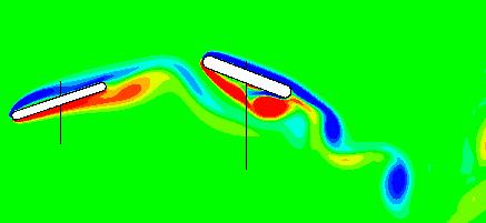
4 For any general function f(t), the average over N cycles is defined as Nτ f = 1 f ( t) dt (5) Nτ 0 hus the average thrust coefficient c is defined as (6) c = 1 ρ U 2 2 c where ρ denotes the fluid density and c is the chord length of the tail fin. Furthermore, the propulsive efficiency, η, is defined 10 as the ratio of useful power to input power (P). p where η p = P U P = = S. y + M. θ U (7) P (8) B. Simulation Results Grid and domain independence studies are critical in order to verify the accuracy of the computation results. Extensive grid and domain independence studies have been carried out in order to ensure that the results are not sensitive to these factors. he grid used in the current simulation is 520 x 240 with the domain size of 30 x 50 as shown in figure 5. he grid size was increased to 700 x 430 and it is observed that the percentage difference for the thrust and lift forces is less than 5% which clearly indicates that the flow in the vicinity of the foils is virtually grid independent. Similarly, the domain size was increased to 40 x 60 with grid size of 577 x 262. he slight increase in the grid size is to maintain comparable grid spacing in the two grids. It is observed that the percentage difference for the thrust and lift forces is less than 3% verifying the domain independence for this study. Details of the grid and domain independence study are given in Akhtar 11 (2003). In configuration I, Figure 6 (A-L) shows vorticity contours during a half cycle of the tail fin in which the fin moves from the bottom-most position to the top-most position. he blue and red contours represent positive and negative vorticity, respectively. Figure 6 A shows the tail fin at the bottom of its cycle. As the fin moves up, the pitch angle also increases (6 B&C). he clockwise vortex is created on the top of the tail fin and is about to be detached (figure 6 D&E). In figure 6 F, the tail fin has reached the mean position and is at its maximum pitch angle of 30. As it moves up further, the pitch angle starts decreasing as shown in figure 6 H. he counter clockwise vortex starts developing below the tail fin near E. he tail fin peaks to its maximum amplitude where the pitch able 2. Comparison of Configuration I & II. Parameter Configuration I ail only Configuration II 108 phase %age increase hrust Coefficient (C ) % Efficiency (η P ) % angle becomes zero. hese pictures depict half the cycle of the tail fin and the rest of the cycle can be obtained as an image of this across the axis of symmetry of the pitching motion. his completes one cycle of the tail fin in which we get a pair of vortices. In configuration II, vorticity contours are shown at the same instant as that of configuration I in order to have direct comparisons between the two cases. In figure 7 A, the vortex shedding is different from its corresponding counterpart. Similarly in figure 7 F, due to the presence of soft dorsal fin upstream of the tail fin, the vortex is formed below the tail fin at almost half its chord length and is significantly bigger. In figure 7 K, a complete vortex is formed at the E of tail fin. In figure 7 K, the counter clockwise vortex is shed, and it is larger in size as compared to that of configuration I. hese pictures also depict half of the cycle of the fins. he thrust, side force and the moment coefficients are plotted against time for comparison of the two cases. Figure 8 shows various locations of the tail fin at different instants. In figure 9, heaving velocity and pitch angle are plotted for different positions of the tail fin at various instants. It is clear that when the fin is at the center position, its heave (vertical) velocity and pitch angle (-ve going up) are at peak values and are minimum at the extreme positions. wo complete cycles are plotted for the thrust coefficient against time in figure 10. Different positions of the tail fin are marked on the x axis corresponding to the thrust at that location on the y-axis. 4

5 A B C D E F G H I J K L Figure 6. Configuration I : ail Fin Only case 5


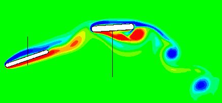
6 A B C D E F G H I J K L Figure 7. Configuration II : Soft Dorsal Fin and ail Fin 6

7 It is observed that there is a significant increase in the thrust of the tail fin due to the presence of the soft dorsal fin, primarily during the phase when the foil accelerates towards its mean position. Similarly in figure 11, the side force is compared for the two cases. As expected, the side force is equal in magnitude but opposite in direction for the two halves of a complete cycle. he moment plot against time is shown in figure 12. he moment coefficient is also symmetric for the two halves of a complete cycle. he thrust and efficiency of the tail fin are calculated and are shown in able-1 for each configuration. he numerical simulations therefore clearly indicate that the presence of the upstream fin can greatly increase the thrust and efficiency of the tail fin. However, it is not sufficient to conclude, based on one set of simulations, that the upstream fin enhances the performance of the downstream fin. For the results of this study to be useful, it is required to: 1) Explain the physical mechanism(s) that is(are) responsible for this performance enhancement. 2) Determine what is/are the key factors that influence this enhancement. Figure 8. Position of the tail fin at different instants. 1&5-Bottom position, 2-Center position (moving up), 3-op position, 4-Center position (moving down) In order to investigate what factors actually affect the performance of the tail fin when there is a soft dorsal fin located upstream, the vorticity plots of the two configurations are placed side by side for a direct comparison. Figure 9. Heave velocity and pitch angle vs time Figure 10. hrust coefficient comparison vs time Figure 11. Side force comparison vs time 7 Figure 12. Moment coefficient comparison vs time
 By observing the velocity vector upstream of the tail fin, it is seen that the effective angle of attack (AOA) of the flow of the tail")

 he early formation of the vortex in Configuration II results in a decrease in pressure on the suction surface of the tail fin.")


8 Moreover a zoom-in view is also shown in figure 13 along with the velocity vectors. he following observations are made regarding this comparison: 1) By observing the velocity vector upstream of the tail fin, it is seen that the effective angle of attack (AOA) of the flow of the tail fin for Configuration II is larger than that of Configuration I. his is defined as the effective AOA as seen by the tail fin. he increase in AOA in Configuration II is basically caused by the opposite sign vortex shed from the soft dorsal fin. 2) he increase in effective AOA leads to LE stall and destabilization of the separated shear layer thus causing the formation of the LE stall vortex as clearly seen in figure 13. 3) he early formation of the vortex in Configuration II results in a decrease in pressure on the suction surface of the tail fin. his increases the pressure differential on the tail fin, which in turn increases the thrust of the tail fin. Details of the pressure forces acting over the pressure and suction sides of tail fin are given in Akhtar 11. 4) he mechanism observed here does not fall into any of the categories proposed by Gopalakrishnan 10. Figure 13. Comparison and Close up view of Configuration I & II (Note that every 6 th vector is plotted in each dimension). C. Phase Difference Study Analysis of the vortex structures indicates that the physics of thrust enhancement is associated with the interaction of a clockwise rotating vortex with the LE of the tail fin as it moves up (and vice versa). It seems clear that the phase lag between the two fins would be a crucial factor since it will determine the timing of the interaction between the dorsal fin vortices and the tail fin LE. hus, it seems evident that the examination of the effect of the phase difference between the two fins would lead to further insights into the physics of this flow. Numerical simulations were carried out assuming different phase differences between fins. With the soft dorsal fin still leading, phase differences of 138, 123, 108, 93, 78, 63, 48, 33 and 18 were used at the same Reynolds number. Figure 14 shows the vorticity plots for different phase differences when the tail fin is at its mean position with maximum pitch angle. It clearly depicts the effect of phase difference on the vortex structure below the tail fin. Figure 14. Vorticity plots for phase difference study 8
9 1. Effect of Phase Difference on hrust of ail Fin Figure 15 shows a plot of thrust coefficient of the tail fin versus phase angle. On the right vertical-axis, the thrust on the tail fin (with the dorsal fin upstream) normalized by the thrust of the tail fin (in the absence of the dorsal fin) is plotted. his gives us a direct measure of the tail fin thrust enhancement due to the presence of the dorsal fin. he encircled value indicates the phase difference of 108, which was based on the initial experimental value. As found before, the thrust is almost twice that of Configuration I. It is interesting to see that as the phase difference between the soft dorsal and the tail fins is increased to 123, the thrust starts to decrease but is still greater than for Configuration I. However, as the phase difference is increased further, the thrust decreases to a value lower than that of Configuration I. his clearly implies that the mere presence of a soft dorsal fin upstream is not always beneficial to swimming. Decreasing the phase difference causes the thrust to increase as shown for the cases of 93 and 78. When the phase difference is 48, the maximum thrust is achieved, which is just over three times the thrust of the single tail fin case. Decreasing the phase difference further does not increase the thrust. 2. Effect of Phase Difference on Efficiency of ail Fin Figure 16 shows the variation of efficiency of the tail fin. he phase difference of 108 is encircled where there is a 50% increase in efficiency. As the phase difference is increased, the efficiency goes down, but it remains nearly 30% larger than that of Configuration I. As the phase difference is reduced, the efficiency increases. At a phase difference of 48, the efficiency is maximum almost 80% more than that of Configuration I. Increasing the phase difference further, begins to reduce the efficiencies. It is observed that, like thrust, efficiency also peaks at 48. Figure 15. hrust coefficient of the tail fin vs Phase difference Figure 16. Efficiency vs Phase difference D. Overall Efficiency of Sunfish In the previous sections, the thrust and efficiency of the tail fin have been discussed with or without the presence of upstream dorsal fin. he performance parameters were discussed and compared only for the tail fin. However, in case of the two-fin system, it is logical to calculate these parameters for the whole system and then to compare it to a single fin. his aspect is significant in designing an AUV having a fish-like propulsive system. he comparison presents an analysis of the cost of having a upstream fin. he overall efficiency is calculated by considering the wasted power of the dorsal fin as well. hus the efficiency of the sunfish can be calculated by the following formula: ( dorsal + tail ) U (9) η p = Pdorsal + Ptail Figure 17 shows the comparison of the thrust of the tail fin and the thrust of the tandem fin system. here is a slight decrease in the overall thrust, which is due to the small amount of drag produced by the soft dorsal fin. he reduced thrust is still higher than the thrust of a single tail fin for the phase angle of 108. Figure 18 shows the comparison of overall efficiency and it follows the same trend but is slightly reduced, as there is a part of wasteful energy being added from the dorsal fin. Still, the efficiency is greater than that of the single fin. his study indicates that the tandem foil system with a suitable phase lag between two fins is better than a single fin. 9
10 Figure 17. hrust vs Phase (Solid line is replotted from Figure 15 for comparison) Figure 18. Efficiency vs Phase (Solid line is replotted from Figure 16 for comparison) E. Wake opology We have shown that the presence of the soft dorsal fin causes the shear layer to destabilize and results in early formation of a vortex. It increases thrust and also results in higher efficiency of the tail fin. Figure 15 shows that the phase difference of 48, produces more thrust than any other phase difference discussed in the study. At the outset, the reason for this is not clear since the size of the LE vortex is about the same for the 48 case as it is for 108 case, observed in figure 19, 20 and 21. Further examination reveals that there is a significant difference in the wake topology for these two cases. For the φ = 108 case, the wake of the tail fin is dominated by the vortices that are generated by the tail. hese vortices are quite widely spaced and do not exhibit any interaction or arrangement. In contrast, for the φ = 48 case, the wake consists of vortices generated both by the dorsal fin as well as the tail fin. Consequently, the mean spacing between the vortices is lower which leads to significant mutual interaction between the vortices, Interestingly, it is observed that one strong vortex from the tail fin arranges itself in a Karman-like vortex street with two vortices (one from the tail and one from the dorsal fin) which are both rotating counter to the single tail fin vortex. he formation of this street forms a directed jet and consequently increases the thrust on the foil. he same is not the true for the φ = 138 case since the vortex topology does not orient to produce a strong directed jet. V. Conclusion wo-dimensional numerical simulations have been used to examine the performance of a foil undergoing flapping motion in the wake of another flapping foil. his configuration attempts to mimic the interaction of the dorsal and tail fin observed in a bluegill sunfish by Drucker & Lauder 4-6. he presence of the upstream flapping foil increases the performance (thrust and efficiency) of the downstream foil by a significant factor. his provides support for the hypothesis of Drucker and Lauder 4-6 that the dorsal fin increases the thrust of the caudal fin though it does not actively participate in the thrust generation. Numerical simulations also allow us to determine the mechanism responsible for this performance enhancement. It is found that vortex structures shed by the upstream fin initiate the formation of a strong leading edge stall vortex on the downstream fin. his stall vortex convects down the surface of the foil and the low pressure associated with this vortex increases the thrust on the downstream foil. he phase lag between the two foils is the key parameter that determines the extent of thrust enhancement. For this particular configuration, the highest performance enhancement is found when the downstream fin motion lags that of the upstream fin by 48. For this phase angle, it is found that the vortex structures in the composite wake of the two foils arrange themselves in a Karman-like vortex street which is known to be the optimal wake topology for thrust production. 10
 108 deg A B D D+ Figure 20.")


11 A D - Vortex shed by dorsal fin - Vortex shed by tail fin B Figure 19. Close up view of figure 7 (H & K) 108 deg A B D D+ Figure 20. Close up view for 48 deg phase A B Figure 21. Close up view for 138 deg phase Acknowledgement We would like to acknowledge George Lauder and Elliot Drucker for providing the bluegill sunfish data and for extensive discussions. RM would like to acknowledge support from ONR MURI grant N00014-D References 1 Sfakiotakis, M., Lane, D.M., Davies, J.B.C Review of Fish Swimming Modes for Aquatic Locomotion. IEEE J. Ocean Eng. Vol. 24(2) 2 riantafyllou, G.S., riantafyllou, M.S., & Grosenbaugh, M.A., Optimal hrust Development in Oscillating Foils with Application to Fish Propulsion, Journal of Fluids and Structures, 7,
12 3 Anderson, J.M., Kerrebrock, P.A he vorticity control unmanned undersea vehicle (VCUUV) An autonomous vehicle employing fish swimming propulsion and maneuvering. Proc. 10 th Int. Symp. Unmanned Untethered Submersible echnology, NH pp Drucker, E.G., Lauder, G.V Locomotor forces on a swimming fish: three-dimensional vortex wake dynamics quantified using digital particle image velocimetry. J. Exp. Bio. 202: Drucker, E.G., Lauder, G.V A hydrodynamic analysis of fish swimming speed: wake structure and locomotor force in slow and fast labriform swimmers. J. Exp. Bio. 203: Drucker, E.G., Lauder, G.V Locomotor function of the dorsal fin in teleost fishes: experimental analysis of wake forces in sunfish. J. Exp. Bio. 204: Udaykumar, H.S., Mittal, R. and Shyy, W Computation of solid liquid phase fronts in the sharp interface limit on fixed grids. J. Comp. Phys., 153, Ye,., Mittal, R.,UdayKumar, H.S. and Shyy, W An accurate cartesian grid method for viscous incompressible flows with complex immersed boundaries, J. Comp. Phys. Vol 156, pp riantafyllou, G.S., & riantafyllou, M.S., Streitlien, K., Efficient Foil Propulsion through Vortex Control, AIAA Journal, 34 (11), pp Gopalkrishnan, R., riantafyllou, M.S., riantafyllou, G.S. & Barrett, D.S Active Vorticity Control in a Shear Flow Using a Flapping Foil. Journal of Fluid Mechanics, 274, Akhtar, I., hrust Augmentation through Active Flow Control Lesson from Bluegill Sunfish, MS hesis, he George Washington University,
Research article Propulsive performance of biologically inspired flapping foils at high Reynolds numbers
 274 The Journal of Experimental Biology 2, 274-279 Published by The Company of Biologists 28 doi:.242/jeb.2849 Research article Propulsive performance of biologically inspired flapping foils at high Reynolds
Analysis of a Hinge-Connected Flapping Plate with an Implemented Torsional Spring Model
 Analysis of a Hinge-Connected Flapping Plate with an Implemented Torsional Spring Model Zach Gaston 1, Hui Wan 2 and Haibo Dong 3 Department of Mechanical & Materials Engineering, Wright State University,
Computational Analysis of Hovering Hummingbird Flight
 Computational Analysis of Hovering Hummingbird Flight Zongxian Liang 1 and Haibo Dong 2 Department of Mechanical & Materials Engineering, Wright State University, Dayton, OH 45435 Mingjun Wei 3 Department
STUDY OF THREE-DIMENSIONAL SYNTHETIC JET FLOWFIELDS USING DIRECT NUMERICAL SIMULATION.
 42 nd AIAA Aerospace Sciences Meeting and Exhibit 5-8 January 2004/Reno, NV STUDY OF THREE-DIMENSIONAL SYNTHETIC JET FLOWFIELDS USING DIRECT NUMERICAL SIMULATION. B.R.Ravi * and R. Mittal, Department of
Simulating Biomimetic (flapping foil) Flows for Comprehension, Reverse Engineering and Design
 Flows for Comprehension, Reverse Engineering and Design") First International Symposium on Marine Propulsors smp 9, rondheim, Norway, June 29 Simulating Biomimetic (flapping foil) Flows for Comprehension, Reverse Engineering and Design Gerasimos K. Politis 1,
First International Symposium on Marine Propulsors smp 9, rondheim, Norway, June 29 Simulating Biomimetic (flapping foil) Flows for Comprehension, Reverse Engineering and Design Gerasimos K. Politis 1,
Computational Analysis of Hovering Hummingbird Flight
 48th AIAA Aerospace Sciences Meeting Including the New Horizons Forum and Aerospace Exposition 4-7 January 2010, Orlando, Florida AIAA 2010-555 Computational Analysis of Hovering Hummingbird Flight Zongxian
Thrust and Efficiency of Propulsion by Oscillating Foils
 Thrust and Efficiency of Propulsion by Oscillating Foils J. Young, J.C.S. Lai, M.Kaya 2 and I.H. Tuncer 2 School of Aerospace, Civil and Mechanical Engineering, UNSW@ADFA, Australian Defence Force Academy,
SENSITIVITY ANALYSIS OF THE FACTORS AFFECTING FORCE GENERATION BY WING FLAPPING MOTION
 Proceedings of the ASME 2013 International Mechanical Engineering Congress and Exposition IMECE2013 November 15-21, 2013, San Diego, California, USA IMECE2013-65472 SENSITIVITY ANALYSIS OF THE FACTORS
Viscous investigation of a flapping foil propulsor
 IOP Conference Series: Materials Science and Engineering PAPER OPEN ACCESS Viscous investigation of a flapping foil propulsor To cite this article: Attapol Posri et al 2018 IOP Conf. Ser.: Mater. Sci.
Active Control of Separated Cascade Flow
 Chapter 5 Active Control of Separated Cascade Flow In this chapter, the possibility of active control using a synthetic jet applied to an unconventional axial stator-rotor arrangement is investigated.
Optimization of Flapping Airfoils for Maximum Thrust and Propulsive Efficiency I. H. Tuncer, M. Kay
 Czech Technical University in Prague Acta Polytechnica Vol. 44 No. 1/2004 Optimization of Flapping Airfoils for Maximum Thrust and Propulsive Efficiency I. H. Tuncer, M. Kay A numerical optimization algorithm
COMPUTATIONAL SIMULATION OF THE FLOW PAST AN AIRFOIL FOR AN UNMANNED AERIAL VEHICLE
 COMPUTATIONAL SIMULATION OF THE FLOW PAST AN AIRFOIL FOR AN UNMANNED AERIAL VEHICLE L. Velázquez-Araque 1 and J. Nožička 2 1 Division of Thermal fluids, Department of Mechanical Engineering, National University
Effects of Unequal Pitch and Plunge Airfoil Motion Frequency on Aerodynamic Response
 Effects of Unequal Pitch and Plunge Airfoil Motion Frequency on Aerodynamic Response C. Webb *, H. Dong Department of Mechanical & Materials Engineering, Wright State University Dayton, OH 45435, Michael
ν δ - 1 -
 ν δ - 1 - δ ν ν δ ν ν - 2 - ρ δ ρ θ θ θ δ τ ρ θ δ δ θ δ δ δ δ τ μ δ μ δ ν δ δ δ - 3 - τ ρ δ ρ δ ρ δ δ δ δ δ δ δ δ δ δ δ - 4 - ρ μ ρ μ ρ ρ μ μ ρ - 5 - ρ τ μ τ μ ρ δ δ δ - 6 - τ ρ μ τ ρ μ ρ δ θ θ δ θ - 7
Vortex-Array Model of a Shear Layer Perturbed by a Periodically Pitching Airfoil
 AIAA Aviation 1- June 1, Atlanta, GA th AIAA Fluid Dynamics Conference AIAA 1-53 Vortex-Array Model of a Shear Layer Perturbed by a Periodically Pitching Airfoil K. Zhang 1 Xi an Jiaotong University, Xi
THE PERFORMANCE OF A NEW IMMERSED BOUNDARY METHOD ON SIMULATING UNDERWATER LOCOMOTION AND SWIMMING
 THE PERFORMANCE OF A NEW IMMERSED BOUNDARY METHOD ON SIMULATING UNDERWATER LOCOMOTION AND SWIMMING Arman Hemmati, Utku Şentürk, Tyler Van Buren, Alexander J. Smits,, Department of Mechanical and Aerospace
An experimental study of the vortex structures in the wake of a piezoelectric flapping plate for Nano Air Vehicle applications
 Graduate Theses and Dissertations Iowa State University Capstones, Theses and Dissertations 9 An experimental study of the vortex structures in the wake of a piezoelectric flapping plate for Nano Air Vehicle
On the generation of a reverse Von Karman street for the controlled cylinder wake in the laminar regime
 On the generation of a reverse Von Karman street for the controlled cylinder wake in the laminar regime Michel Bergmann, Laurent Cordier, Jean-Pierre Brancher To cite this version: Michel Bergmann, Laurent
Lift Enhancement by Dynamically Changing Wingspan. in Forward Flapping Flight (09/10/2013)
") Lift Enhancement by Dynamically Changing Wingspan in Forward Flapping Flight Shizhao Wang 1, Xing Zhang 1, Guowei He 1a), ianshu Liu 2,1 (09/10/2013) 1 he State Key Laboratory of Nonlinear Mechanics, Institute
Lift Enhancement by Dynamically Changing Wingspan in Forward Flapping Flight Shizhao Wang 1, Xing Zhang 1, Guowei He 1a), ianshu Liu 2,1 (09/10/2013) 1 he State Key Laboratory of Nonlinear Mechanics, Institute
A Jet Formation Criterion for Synthetic Jet Actuators
 AIAA 3-636 A Jet Formation Criterion for Synthetic Jet Actuators Yogen Utturkar, Ryan Holman, Rajat Mittal, Bruce Carroll, Mark Sheplak, and Louis Cattafesta University of Florida Gainesville, FL The George
Characteristics of flow over traveling wavy foils in a side-by-side arrangement
 PHYSICS OF FLUIDS 19, 057107 2007 Characteristics of flow over traveling wavy foils in a side-by-side arrangement Gen-Jin Dong and Xi-Yun Lu a Department of Modern Mechanics, University of Science and
SIMULATION OF GAS FLOW OVER MICRO-SCALE AIRFOILS USING A HYBRID CONTINUUM-PARTICLE APPROACH
 33rd AIAA Fluid Dynamics Conference and Exhibit 3-6 June 3, Orlando, Florida AIAA 3-44 33 rd AIAA Fluid Dynamics Conference and Exhibit / Orlando, Florida / 3-6 Jun 3 SIMULATION OF GAS FLOW OVER MICRO-SCALE
φ(r, θ, t) = a 2 U(t) cos θ. (7.1)
 = a 2 U(t) cos θ. (7.1)") BioFluids Lectures 7-8: Slender Fish Added Mass for Lateral Motion At high Reynolds number, most of the effort required in swimming is pushing water out of the way, that is our energy goes in providing
BioFluids Lectures 7-8: Slender Fish Added Mass for Lateral Motion At high Reynolds number, most of the effort required in swimming is pushing water out of the way, that is our energy goes in providing
arxiv: v1 [physics.flu-dyn] 7 Mar 2019
![arxiv: v1 [physics.flu-dyn] 7 Mar 2019](/thumbs/94/119611787.jpg "arxiv: v1 [physics.flu-dyn] 7 Mar 2019") This draft was prepared using the LaTeX style file belonging to the Journal of Fluid Mechanics 1 arxiv:1903.03050v1 [physics.flu-dyn] 7 Mar 2019 Universal scaling law in drag-to-thrust transition of flapping
This draft was prepared using the LaTeX style file belonging to the Journal of Fluid Mechanics 1 arxiv:1903.03050v1 [physics.flu-dyn] 7 Mar 2019 Universal scaling law in drag-to-thrust transition of flapping
Numerical Investigation of Thermal Performance in Cross Flow Around Square Array of Circular Cylinders
 Numerical Investigation of Thermal Performance in Cross Flow Around Square Array of Circular Cylinders A. Jugal M. Panchal, B. A M Lakdawala 2 A. M. Tech student, Mechanical Engineering Department, Institute
Aeroelastic Analysis Of Membrane Wings
 Aeroelastic Analysis Of Membrane Wings Soumitra P. Banerjee and Mayuresh J. Patil Virginia Polytechnic Institute and State University, Blacksburg, Virginia 46-3 The physics of flapping is very important
Vortex structures in the wake of a buoyant tethered cylinder at moderate to high reduced velocities
 European Journal of Mechanics B/Fluids 23 (2004) 127 135 Vortex structures in the wake of a buoyant tethered cylinder at moderate to high reduced velocities K. Ryan, M.C. Thompson, K. Hourigan Fluids Laboratory
Numerical Simulation of Unsteady Flow with Vortex Shedding Around Circular Cylinder
 Numerical Simulation of Unsteady Flow with Vortex Shedding Around Circular Cylinder Ali Kianifar, Edris Yousefi Rad Abstract In many applications the flow that past bluff bodies have frequency nature (oscillated)
Numerical Analysis of Unsteady Viscous Flow through a Weis-Fogh-Type Water Turbine
 International Conference on Emerging Trends in Computer and Image Processing (ICETCIP'014) Dec. 15-16, 014 Pattaya (Thailand) Numerical Analysis of Unsteady Viscous Flow through a Weis-Fogh-Type Water
Numerical study of the effects of trailing-edge bluntness on highly turbulent hydro-foil flows
 Numerical study of the effects of trailing-edge bluntness on highly turbulent hydro-foil flows T. Do L. Chen J. Tu B. Anderson 7 November 2005 Abstract Flow-induced noise from fully submerged lifting bodies
1. Fluid Dynamics Around Airfoils
 1. Fluid Dynamics Around Airfoils Two-dimensional flow around a streamlined shape Foces on an airfoil Distribution of pressue coefficient over an airfoil The variation of the lift coefficient with the
Computational Fluid Dynamics Study Of Fluid Flow And Aerodynamic Forces On An Airfoil S.Kandwal 1, Dr. S. Singh 2
 Computational Fluid Dynamics Study Of Fluid Flow And Aerodynamic Forces On An Airfoil S.Kandwal 1, Dr. S. Singh 2 1 M. Tech Scholar, 2 Associate Professor Department of Mechanical Engineering, Bipin Tripathi
Fig. 1. Bending-Torsion Foil Flutter
 27 TH INTERNATIONAL CONGRESS OF THE AERONAUTICAL SCIENCES EXTRACTING POWER IN JET STREAMS: PUSHING THE PERFORMANCE OF FLAPPING WING TECHNOLOGY M.F. Platzer*, M.A. Ashraf**, J. Young**, and J.C.S. Lai**
Lecture-4. Flow Past Immersed Bodies
 Lecture-4 Flow Past Immersed Bodies Learning objectives After completing this lecture, you should be able to: Identify and discuss the features of external flow Explain the fundamental characteristics
[N175] Development of Combined CAA-CFD Algorithm for the Efficient Simulation of Aerodynamic Noise Generation and Propagation
![[N175] Development of Combined CAA-CFD Algorithm for the Efficient Simulation of Aerodynamic Noise Generation and Propagation](/thumbs/95/123895144.jpg "[N175] Development of Combined CAA-CFD Algorithm for the Efficient Simulation of Aerodynamic Noise Generation and Propagation") The 32nd International Congress and Exposition on Noise Control Engineering Jeju International Convention Center, Seogwipo, Korea, August 25-28, 2003 [N175] Development of Combined CAA-CFD Algorithm for
The 32nd International Congress and Exposition on Noise Control Engineering Jeju International Convention Center, Seogwipo, Korea, August 25-28, 2003 [N175] Development of Combined CAA-CFD Algorithm for
A flow control mechanism in wing flapping with stroke asymmetry during insect forward flight
 Acta Mech Sinica (2005) 21, 218 227 DOI 10.1007/s10409-005-0032-z RESEARCH PAPER Yongliang Yu Binggang Tong A flow control mechanism in wing flapping with stroke asymmetry during insect forward flight
A fundamental study of the flow past a circular cylinder using Abaqus/CFD
 A fundamental study of the flow past a circular cylinder using Abaqus/CFD Masami Sato, and Takaya Kobayashi Mechanical Design & Analysis Corporation Abstract: The latest release of Abaqus version 6.10
Aerodynamic force analysis in high Reynolds number flows by Lamb vector integration
 Aerodynamic force analysis in high Reynolds number flows by Lamb vector integration Claudio Marongiu, Renato Tognaccini 2 CIRA, Italian Center for Aerospace Research, Capua (CE), Italy E-mail: c.marongiu@cira.it
Vortex wake and energy transitions of an oscillating cylinder at low Reynolds number
 ANZIAM J. 46 (E) ppc181 C195, 2005 C181 Vortex wake and energy transitions of an oscillating cylinder at low Reynolds number B. Stewart J. Leontini K. Hourigan M. C. Thompson (Received 25 October 2004,
Mestrado Integrado em Engenharia Mecânica Aerodynamics 1 st Semester 2012/13
 Mestrado Integrado em Engenharia Mecânica Aerodynamics 1 st Semester 212/13 Exam 2ª época, 2 February 213 Name : Time : 8: Number: Duration : 3 hours 1 st Part : No textbooks/notes allowed 2 nd Part :
Passive propulsion in vortex wakes
 J. Fluid Mech. (26), vol. 549, pp. 385 42. c 26 Cambridge University Press doi:1.117/s2211257925 Printed in the United Kingdom 385 Passive propulsion in vortex wakes By D. N. B E A L 1, F. S. H O V E R
Eulerian simulations of oscillating airfoils in power extraction regime
 Advances in Fluid Mechanics VI 245 Eulerian simulations of oscillating airfoils in power extraction regime G. Dumas & T. Kinsey Laval University, Quebec, Canada Abstract A wing that is both heaving and
B. Simpson, S. Licht, F. S. Hover and M. S. Triantafyllou
 ENERGY EXTRACTION THROUGH FLAPPING FOILS B. Simpson, S. Licht, F. S. Hover and M. S. Triantafyllou MITS G 08-52 Sea Grant College Program Massachusetts Institute of Technology Cambridge, Massachusetts
Effect of wavelength of fish-like undulation of a hydrofoil in a free-stream flow
 Sādhanā Vol. 42, No. 4, April 2017, pp. 585 595 DOI 10.1007/s12046-017-0619-7 Ó Indian Academy of Sciences Effect of wavelength of fish-like undulation of a hydrofoil in a free-stream flow THEKKETHIL NAMSHAD,
Student name: This is a closed book examination. You are allowed 1 sheet of 8.5 x 11 paper with notes.
 13.012 Marine Hydrodynamics for Ocean Engineers Fall 2004 Quiz #2 Student name: This is a closed book examination. You are allowed 1 sheet of 8.5 x 11 paper with notes. For the problems in Section A, fill
A Numerical Study of Vortex-Dominated Flow around an Oscillating Airfoil with High-Order Spectral Difference Method
 48th AIAA Aerospace Sciences Meeting Including the New Horizons Forum and Aerospace Exposition 4-7 January, Orlando, Florida AIAA -76 A Numerical Study of Vortex-Dominated Flow around an Oscillating Airfoil
CFD Approach to Steady State Analysis of an Underwater Glider
 CFD Approach to Steady State Analysis of an Underwater Glider Yogang Singh, S.K. Bhattacharyya and V.G. Idichandy Department of Ocean Engineering IIT Madras, Chennai India Abstract Underwater glider moves
Oscillating foils of high propulsive efficiency
 J. Fluid Mech. (998), vol. 36, pp. 4 72. Printed in the United Kingdom c 998 Cambridge University Press 4 Oscillating foils of high propulsive efficiency By J. M. ANDERSON,2, K. STREITLIEN, D. S. BARRETT
COURSE ON VEHICLE AERODYNAMICS Prof. Tamás Lajos University of Rome La Sapienza 1999
 COURSE ON VEHICLE AERODYNAMICS Prof. Tamás Lajos University of Rome La Sapienza 1999 1. Introduction Subject of the course: basics of vehicle aerodynamics ground vehicle aerodynamics examples in car, bus,
Relationship between Unsteady Fluid Force and Vortex Behavior around a Discoid Airfoil Simulating a Hand of Swimmer
 45 * Relationship between Unsteady Fluid Force and Vortex Behavior around a Discoid Airfoil Simulating a Hand of Swimmer Hiroaki HASEGAWA, Department of Mechanical Engineering, Akita University Jun WATANABE,
IN-LINE MOTION CAUSES HIGH THRUST AND EFFICIENCY IN FLAPPING FOILS THAT USE POWER DOWNSTROKE
 IN-LINE MOTION CAUSES HIGH THRUST AND EFFICIENCY IN FLAPPING FOILS THAT USE POWER DOWNSTROKE S. C. Licht, M. S. Wibawa, F. S. Hover and M. S. Triantafyllou MITSG 1-18 Sea Grant College Program Massachusetts
Experimental characterization of flow field around a square prism with a small triangular prism
 Journal of Mechanical Science and Technology 29 (4) (2015) 1649~1656 www.springerlink.com/content/1738-494x OI 10.1007/s12206-015-0336-2 Experimental characterization of flow field around a square prism
Enclosure enhancement of flight performance
 THEORETICAL & APPLIED MECHANICS LETTERS, 23 (21) Enclosure enhancement of flight performance Mehdi Ghommem, 1, a) Daniel Garcia, 2 Victor M. Calo 3 1) Center for Numerical Porous Media (NumPor), King Abdullah
SHEAR LAYER REATTACHMENT ON A SQUARE CYLINDER WITH INCIDENCE ANGLE VARIATION
 Seventh International Conference on CFD in the Minerals and Process Industries CSIRO, Melbourne, Australia 9- December 9 SHEAR LAYER REATTACHMENT ON A SQUARE CYLINDER WITH INCIDENCE ANGLE VARIATION Priyanka
Numerical Investigation of Vortex Induced Vibration of Two Cylinders in Side by Side Arrangement
 Numerical Investigation of Vortex Induced Vibration of Two Cylinders in Side by Side Arrangement Sourav Kumar Kar a, 1,, Harshit Mishra a, 2, Rishitosh Ranjan b, 3 Undergraduate Student a, Assitant Proffessor
(This is a sample cover image for this issue. The actual cover is not yet available at this time.)
") (This is a sample cover image for this issue. The actual cover is not yet available at this time.) This is an open access article which appeared in a ournal published by Elsevier. This article is free
(This is a sample cover image for this issue. The actual cover is not yet available at this time.) This is an open access article which appeared in a ournal published by Elsevier. This article is free
When vortices stick: an aerodynamic transition in tiny insect flight
 The Journal of Experimental Biology 7, 7-88 Published by The Company of Biologists 4 doi:.4/jeb.8 7 When vortices stick: an aerodynamic transition in tiny insect flight Laura A. Miller* and Charles S.
Influence of the Fluid-Structure Interaction on the Modal Analysis, and on the Dynamics of Composite Monofin : Optimization of Propulsion
 2ème Congrès Français de Mécanique Bordeaux, 26 au 3 août 23 Influence of the Fluid-Structure Interaction on the Modal Analysis, and on the Dynamics of Composite Monofin : Optimization of Propulsion A.
A COMPUTATIONAL FLUID DYNAMICS STUDY OF CLAP AND FLING IN THE SMALLEST INSECTS. Laura A. Miller* and Charles S. Peskin**
 A COMPUTATIONAL FLUID DYNAMICS STUDY OF CLAP AND FLING IN THE SMALLEST INSECTS Laura A. Miller* and Charles S. Peskin** *Department of Mathematics, University of Utah, 155 South 1400 East, Salt Lake City,
An Experimental Investigation on the Asymmetric Wake Formation of an Oscillating Airfoil
 51st AIAA Aerospace Sciences Meeting including the New Horizons Forum and Aerospace Exposition 07-10 January 2013, Grapevine (Dallas/Ft. Worth Region), Texas AIAA 2013-0794 An Experimental Investigation
Unsteady Force Generation and Vortex Dynamics of Pitching and Plunging Flat Plates at Low Reynolds Number
 49th AIAA Aerospace Sciences Meeting including the New Horizons Forum and Aerospace Exposition 4-7 January 2011, Orlando, Florida AIAA 2011-220 Unsteady Force Generation and Vortex Dynamics of Pitching
REPORT DOCUMENTATION PAGE
 REPORT DOCUMENTATION PAGE Form Approved OMB NO. 0704-0188 The public reporting burden for this collection of information is estimated to average 1 hour per response, including the time for reviewing instructions,
CFD STUDY OF MASS TRANSFER IN SPACER FILLED MEMBRANE MODULE
 GANIT J. Bangladesh Math. Soc. (ISSN 1606-3694) 31 (2011) 33-41 CFD STUDY OF MASS TRANSFER IN SPACER FILLED MEMBRANE MODULE Sharmina Hussain Department of Mathematics and Natural Science BRAC University,
This document is downloaded from DR-NTU, Nanyang Technological University Library, Singapore.
 This document is downloaded from DR-NTU, Nanyang Technological University Library, Singapore. Title Numeric simulation on the performance of an undulating fin in the wake of a periodic illating plate Author(s)
Effect of Liquid Viscosity on Sloshing in A Rectangular Tank
 International Journal of Research in Engineering and Science (IJRES) ISSN (Online): 2320-9364, ISSN (Print): 2320-9356 Volume 5 Issue 8 ǁ August. 2017 ǁ PP. 32-39 Effect of Liquid Viscosity on Sloshing
Numerical investigation on vortex-induced motion of a pivoted cylindrical body in uniform flow
 Fluid Structure Interaction VII 147 Numerical investigation on vortex-induced motion of a pivoted cylindrical body in uniform flow H. G. Sung 1, H. Baek 2, S. Hong 1 & J.-S. Choi 1 1 Maritime and Ocean
Numerical Investigation of the Fluid Flow around and Past a Circular Cylinder by Ansys Simulation
 , pp.49-58 http://dx.doi.org/10.1457/ijast.016.9.06 Numerical Investigation of the Fluid Flow around and Past a Circular Cylinder by Ansys Simulation Mojtaba Daneshi Department of Mechanical Engineering,
INTERNATIONAL JOURNAL OF APPLIED ENGINEERING RESEARCH, DINDIGUL Volume 1, No 3, 2010
 CFD analysis of 2D unsteady flow around a square cylinder Gera.B, Pavan K. Sharma, Singh R.K Reactor Safety Division, Bhabha Atomic Research Centre, Trombay, Mumbai, India 400085 pa1.sharma@gmail.com ABSTRACT
Application of a Non-Linear Frequency Domain Solver to the Euler and Navier-Stokes Equations
 Application of a Non-Linear Frequency Domain Solver to the Euler and Navier-Stokes Equations Matthew McMullen and Antony Jameson and Juan J. Alonso Dept. of Aeronautics & Astronautics Stanford University
Numerical Simulation of Flow Separation Control using Multiple DBD Plasma Actuators
 Journal of Applied Fluid Mechanics, Vol. 9, No. 4, pp. 1865-1875, 2016. Available online at www.jafmonline.net, ISSN 1735-3572, EISSN 1735-3645. DOI: 10.18869/acadpub.jafm.68.235.25325 Numerical Simulation
On the Aerodynamic Performance of Dragonfly Wing Section in Gliding Mode
 Advances in Aerospace Science and Applications. ISSN 2277-3223 Volume 3, Number 3 (2013), pp. 227-234 Research India Publications http://www.ripublication.com/aasa.htm On the Aerodynamic Performance of
An experimental study of the unsteady vortex structures in the wake of a root-fixed flapping wing
 Exp Fluids (11) 51:37 359 DOI 1.17/s38-11-15-z RESEARCH ARTICLE An experimental study of the unsteady vortex structures in the wake of a root-fixed flapping wing Hui Hu Lucas Clemons Hirofumi Igarashi
Simulations of optimized anguilliform swimming
 4841 The Journal of Experimental iology 9, 4841-4857 Published by The Company of iologists 6 doi:1.14/jeb.56 imulations of optimized anguilliform swimming tefan Kern and Petros Koumoutsakos* Institute
K. M. Isaac, P. Shivaram + University of Missouri-Rolla Rolla, MO T. DalBello NASA Glenn Research Center
 Low Re, High α Aerodynamics with Controlled Wing Kinematics K. M. Isaac, P. Shivaram + University of Missouri-Rolla Rolla, MO 65409 isaac@umr.edu T. DalBello NASA Glenn Research Center ABSTRACT Numerical
Applied Fluid Mechanics
 Applied Fluid Mechanics 1. The Nature of Fluid and the Study of Fluid Mechanics 2. Viscosity of Fluid 3. Pressure Measurement 4. Forces Due to Static Fluid 5. Buoyancy and Stability 6. Flow of Fluid and
OSCILLATING AERO-WING MODEL IN THE QUASI-STEADY DOMAIN A REFERENCE FOR SUSTAINED ANIMAL FLIGHT AND MICRO AIR VEHICLES
 P. Freymuth, Int. Journal of Design & Nature. Vol. 1, No. 2 (2007) 87 99 OSCILLATING AERO-WING MODEL IN THE QUASI-STEADY DOMAIN A REFERENCE FOR SUSTAINED ANIMAL FLIGHT AND MICRO AIR VEHICLES P. FREYMUTH
Free Swimming Bio-Inspired Hydrofoils in Unsteady Ground Effect
 Lehigh University Lehigh Preserve Theses and Dissertations 2018 Free Swimming Bio-Inspired Hydrofoils in Unsteady Ground Effect Jackson Heath Cochran-Carney Lehigh University, jhcc2013@gmail.com Follow
VORTICITY FIELD EVOLUTION IN A FORCED WAKE. Richard K. Cohn Air Force Research Laboratory Edwards Air Force Base, CA 92524
 Proceedings of the st International Symposium on Turbulence and Shear Flow Phenomena, Santa Barbara, CA, Sep. 5, 999, Eds. Banerjee, S. and Eaton, J. K., pp. 9-96. VORTICITY FIELD EVOLUTION IN A FORCED
An Experimental Investigation on the Wake Flow Characteristics of Tandem Flapping Wings
 6th AIAA Theoretical Fluid Mechanics Conference 27-30 June 2011, Honolulu, Hawaii AIAA 2011-3120 An Experimental Investigation on the Wake Flow Characteristics of Tandem Flapping Wings Anand Gopa Kumar
Routine turning maneuvers of koi carp Cyprinus carpio koi: effects of turning rate on kinematics and hydrodynamics
 4379 The Journal of Experimental Biology 21, 4379-4389 Published by The Company of Biologists 27 doi:1.1242/jeb.9787 Routine turning maneuvers of koi carp Cyprinus carpio koi: effects of turning rate on
Motion Kinematics vs. Angle of Attack Effects in High-Frequency Airfoil Pitch/Plunge
 Motion Kinematics vs. Angle of Attack Effects in High-Frequency Airfoil Pitch/Plunge Michael V. OL 1 Air Force Research Laboratory Wright-Patterson AFB, OH 45433 Haibo Dong 2 and Charles Webb 3 Department
RESEARCH ARTICLE Aerodynamic effects of corrugation in flapping insect wings in hovering flight
 3 The Journal of Experimental iology, 3-. Published by The Company of iologists Ltd doi:./jeb.6375 RESERCH RTIE erodynamic effects of corrugation in flapping insect wings in hovering flight Xue Guang Meng*,
Application of a Virtual-Boundary Method for the Numerical Study of Oscillations Developing Behind a Cylinder Near A Plane Wall
 Fluid Dynamics, Vol. 39, No. 1, 2004, pp. 61 68. Translated from Izvestiya Rossiiskoi Academii Nauk, Mekhanika Zhidkosti i Gaza, No. 1, 2004, pp. 69 77. Original Russian Text Copyright 2004 by Kit, Nikitin,
AN ABSTRACT OF THE THESIS OF
 AN ABSTRACT OF THE THESIS OF Kevin J. Drost for the degree of Honors Baccalaureate of Science in Mechanical Engineering presented May 21, 2010. Title: Direct Numerical Simulation of a Flat Wing with a
Chapter 6: Incompressible Inviscid Flow
 Chapter 6: Incompressible Inviscid Flow 6-1 Introduction 6-2 Nondimensionalization of the NSE 6-3 Creeping Flow 6-4 Inviscid Regions of Flow 6-5 Irrotational Flow Approximation 6-6 Elementary Planar Irrotational
Implicit numerical scheme based on SMAC method for unsteady incompressible Navier-Stokes equations
 172 Pet.Sci.(28)5:172-178 DOI 1.17/s12182-8-27-z Implicit numerical scheme based on SMAC method for unsteady incompressible Navier-Stokes equations Li Zhenlin and Zhang Yongxue School of Mechanical and
Two-dimensional model problem to explain counter-rotating vortex pair formation in a transverse jet
 PHYSICS OF FLUIDS 18, 085103 2006 Two-dimensional model problem to explain counter-rotating vortex pair formation in a transverse jet Suman Muppidi and Krishnan Mahesh Aerospace Engineering & Mechanics,
Modeling and numerical simulations of swimmers
 Plafrim, may 31, 2011 p. 1 Modeling and numerical simulations of swimmers Michel Bergmann INRIA Bordeaux Sud-Ouest, project-team MC2 Institut de Mathématiques Appliquées de Bordeaux 33405 TALENCE cedex,
Non-invasive measurement of instantaneous forces during aquatic locomotion: a case study of the bluegill sunfish pectoral fin
 685 The Journal of Experimental Biology 21, 685-698 Published by The Company of Biologists 27 doi:1.1242/jeb.2692 Non-invasive measurement of instantaneous forces during aquatic locomotion: a case study
Implementing a Partitioned Algorithm for Fluid-Structure Interaction of Flexible Flapping Wings within Overture
 10 th Symposimum on Overset Composite Grids and Solution Technology, NASA Ames Research Center Moffett Field, California, USA 1 Implementing a Partitioned Algorithm for Fluid-Structure Interaction of Flexible
A computational fluid dynamics of clap and fling in the smallest insects
 The Journal of Experimental Biology 8, 95- Published by The Company of Biologists 5 doi:.4/jeb.376 95 A computational fluid dynamics of clap and fling in the smallest insects Laura A. Miller, * and Charles
ENERGY PERFORMANCE IMPROVEMENT, FLOW BEHAVIOR AND HEAT TRANSFER INVESTIGATION IN A CIRCULAR TUBE WITH V-DOWNSTREAM DISCRETE BAFFLES
 Journal of Mathematics and Statistics 9 (4): 339-348, 2013 ISSN: 1549-3644 2013 doi:10.3844/jmssp.2013.339.348 Published Online 9 (4) 2013 (http://www.thescipub.com/jmss.toc) ENERGY PERFORMANCE IMPROVEMENT,
Direct Numerical Simulations of Plunging Airfoils
 48th AIAA Aerospace Sciences Meeting Including the New Horizons Forum and Aerospace Exposition 4-7 January 010, Orlando, Florida AIAA 010-78 Direct Numerical Simulations of Plunging Airfoils Yves Allaneau
Heat Transfer Enhancement using Synthetic Jet Actuators in Forced Convection Water Filled Micro-Channels
 Heat Transfer Enhancement using Synthetic Jet Actuators in Forced Convection Water Filled Micro-Channels V. Timchenko 1, J.A. Reizes 1, E. Leonardi 1, F. Stella 2 1 School of Mechanical and Manufacturing
A simplified model for a small propeller with different airfoils along the blade
 A simplified model for a small propeller with different airfoils along the blade Kamal A. R. Ismail 1) and *Célia V. A. G. Rosolen 2) 1), 2) State University of Campinas, Faculty of Mechanical Engineering,
(3) BIOMECHANICS of LOCOMOTION through FLUIDS
 BIOMECHANICS of LOCOMOTION through FLUIDS") (3) BIOMECHANICS of LOCOMOTION through FLUIDS Questions: - Explain the biomechanics of different modes of locomotion through fluids (undulation, rowing, hydrofoils, jet propulsion). - How does size influence
(3) BIOMECHANICS of LOCOMOTION through FLUIDS Questions: - Explain the biomechanics of different modes of locomotion through fluids (undulation, rowing, hydrofoils, jet propulsion). - How does size influence
Flow Control around Bluff Bodies by Attached Permeable Plates
 Flow Control around Bluff Bodies by Attached Permeable Plates G. M. Ozkan, H. Akilli Abstract The aim of present study is to control the unsteady flow structure downstream of a circular cylinder by use
Numerical Study of Natural Unsteadiness Using Wall-Distance-Free Turbulence Models
 Numerical Study of Natural Unsteadiness Using Wall-Distance-Free urbulence Models Yi-Lung Yang* and Gwo-Lung Wang Department of Mechanical Engineering, Chung Hua University No. 707, Sec 2, Wufu Road, Hsin
Module 2: External Flows Lecture 12: Flow Over Curved Surfaces. The Lecture Contains: Description of Flow past a Circular Cylinder
 The Lecture Contains: Description of Flow past a Circular Cylinder Experimental Results for Circular Cylinder Flow file:///d /Web%20Course%20(Ganesh%20Rana)/Dr.%20gautam%20biswas/Final/convective_heat_and_mass_transfer/lecture12/12_1.htm[12/24/2014
Fluid transport and coherent structures of translating and flapping wings
 Manuscript submitted to Chaos for special issue on Lagrangian Coherent Structures Fluid transport and coherent structures of translating and flapping wings Jeff D. Eldredge and Kwitae Chong Mechanical