3. Alternating Current
|
|
|
- Kelley Mosley
- 6 years ago
- Views:
Transcription
1 3. Alernaing Curren TOPCS Definiion and nroducion AC Generaor Componens of AC Circuis Series LRC Circuis Power in AC Circuis Transformers & AC Transmission
2 nroducion o AC The elecric power ou of a home or office power socke is in he form of alernaing curren (AC), as opposed o he direc curren (DC) of a baery. Alernaing curren is used because i is easier o ranspor, and easier o ransform from one volage o anoher using a ransformer. n Nigeria and UK, he frequency of oscillaion of AC is 50 Hz. n he USA i is 60 Hz. November 7, 007
3 The AC Generaor November 7, 007
4 A coil of area A and N urns roaing wih consan angular velociy in a uniform magneic field produces a sinusoidal emf. The slip rings and brushes allow he coil o roae wihou wising he connecing wires. Such a device is called a generaor.
5 Alernaing Curren Generaor Con d ε ε sin m d i sin( φ) December 5, 007 d
6 akes power o roae he coil, bu ha power can come from: moving waer (a waer urbine) air (windmill) gasoline moor (as in a car) seam (as in a nuclear power plan). November 7, 007
7 NBA d NBA and NBA m m m δ φ ε δ φ δ θ θ φ ) sin( ) ( November 7, 007 f f frequency NBA d m π δ ε ε δ ε ; ) sin( ) sin( + +
8 RLC Circuis wih AC Power When an RLC circui is driven wih an AC power source, he driving frequency d is he frequency of he power source, while he circui can have a differen resonan frequency. 1/ LC ( R / L) Le s look a hree differen circuis driven by an AC EMF. The device conneced o he EMF is called he load. Wha we are ineresed in is how he volage oscillaions across he load relae o he curren oscillaions. We will find ha he phase relaionships change, depending on he ype of load (resisive, capaciive, or inducive). December 5, 007
9 Leading & Lagging in Phasors The figure shows, in (a), a sine curve S() sin(d) and hree oher sinusoidal curves A(), B(), and C(), each of he form sin(d φ). (a) Rank he hree curves according o he value of φ, mos posiive firs and mos negaive las. Answer (a) C, B, A November 7, 007
10 (b) Which curve corresponds o which phasor in par (b) of he figure? (c) Which curve leads he ohers? (b) (c) 1 >A A >B 3 >S 4 >C November 7, 007
11 A Resisive Load Phasor Diagram: shows he insananeous phase of eiher volage or curren. For a resisor, he curren follows he volage, so he volage and curren are in phase (φ 0). φ f v R R sin d Then i R R sin d R R sin d December 5, 007

12 Resisive Load Con d November 7, 007
13 Resisive Load CURRENT is in phase wih OLTAGE November 7, 007
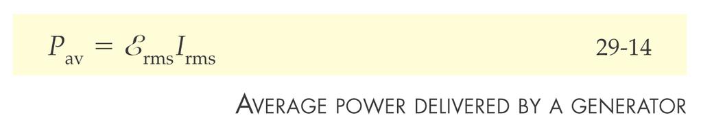
14 AC Power in a Resisor Poenial drop across he resisor, R Curren in he resisor Power dissipaed in he resisor, P Average power dissipaed in he resisor P average ε ε R max R, R, R R, R P P av R ( ) av R ( ( ) R ( )) av R
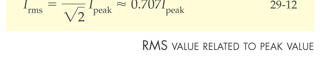
15 Roo-Mean-Square alues
16 A Capaciive Load For a capaciive load, he volage across he capacior is proporional o he charge q Q vc sind C C Bu he curren is he ime derivaive of he charge i C dq d C d C d n analogy o he resisance, which is he proporionaliy consan beween curren and volage, we define he capaciive reacance as 1 X C C So ha i. dc C X C The phase relaionship is ha φ 90º, and curren leads volage. d December 5, 007

17 Capaciive Load Con d November 7, 007
 C, rms 1 C Power delivered by he emf in he capacior: nsananeous and")
18 Capaciors in Alernaing Curren Circuis The poenial drop lags he curren by 90º Q C C Q C dq d ε ε C, max C C, sin CAPACTE REACTANCE C, C, 1 C C, 1 C ( + ; rms π ) C, rms 1 C Power delivered by he emf in he capacior: nsananeous and average
19 Capaciive Load CURRENT Leads OLTAGE By 90 degrees November 7, 007
20 An nducive Load For an inducive load, he volage across he inducor is proporional o he ime derivaive of he curren v L di L d Bu he curren is he ime derivaive of he charge i L L L sin d d d L d L L Again in analogy o he resisance, which is he proporionaliy consan beween curren and volage, we define he inducive reacance as X L L So ha il d. X L The phase relaionship is ha φ +90º, and curren lags volage. L d December 5, 007
21 nducive Load Con d November 7, 007
 L, L ( ; rms L, rms L π ) nsananeous power delivered by he emf o he inducor is no zero The average power delivered by he emf o he inducor is")
22 nducors in Alernaing Curren Circuis L d d d L ε ε max L, d L, L, L, sin L L L NDUCTE REACTANCE The poenial drop across he inducor led he curren 90º (ou of phase) L, L ( ; rms L, rms L π ) nsananeous power delivered by he emf o he inducor is no zero The average power delivered by he emf o he inducor is zero.
23 nducive Load CURRENT Lags OLTAGE By 90 degrees November 7, 007
24 Summary Table Circui Elemen Symbol Resisance or Reacance Phase of Curren Phase Consan Ampliude Relaion Resisor R R n phase wih v R 0º (0 rad) R R R Capacior C X C 1/ d C Leads v R by 90º 90º ( π/) C C X C nducor L X L d L Lags v R by 90º +90º (π/) L L X L December 5, 007
25 Driven RLC Series Circuis The Kirchhoff s rules govern he behavior of poenial drops and curren across he circui. (a) When any closed-loop is raversed, he algebraic sum of he changes of poenial mus equal zero (loops rule) (a) A any juncion (branch poin) in a circui where he curren can be divided, he sum of he currens ino he juncion mus equal he sum of he currens ou of he juncion (juncion rule)


26 ) ( ;,, δ C Q R d dq d Q d L d dq C Q R d d L app app
27 Phasors Poenial drop across a resisor can be represened by a vecor R, which is called a phasor. Then, he poenial drop across he resisor R, is he x componen of vecor R, Poenial drop across a series RLC circui d app L + R + d Q C
28 Power delivered o he series RLC circui δ ε δ ε π ε ε 1 ) (, rms app rms av rms rms av R R P resisor he in dissipaed R P P P Power facor: δ δ δ δ 1 / /,,,, rms rms app app app rms app rms av P Z and Z R as Z R P
29 The Transformer A ransformer is a device o raise or lower he volage in a circui wihou an appreciable loss of power. Power losses arise from Joule heaing in he small resisances in boh coils, or in currens loops (eddy currens) wihin he iron core. An ideal ransformer is ha in which hese losses do no occur, 100% efficiency. Acual ransformers reach 90-95% efficiency Because of he iron core, here is a large magneic flux hrough each coil, even when he magneizing curren m in he primary circui is very small. The primary circui consiss of an ac generaor and a pure inducance (we consider a negligible resisance for he coil). Then he average power dissipaed in he primary coil is zero. Why?: The magneizing curren in he primary coil and he volage drop across he primary coil are ou of phase by 90º Secondary coil open circui The poenial drop across he primary coil is 1 N N 1 dφ d urn f here is no flux leakage ou of he iron core, he flux hrough each urn is he same for boh coils, and hen dφ d urn N N 1 1

30 The Transformer A resisance R, load resisance, in he secondary circui A curren will be in he secondary coil, which is in phase wih he poenial drop across he resisance. This curren ses up and addiional flux Φ urn hrough each urn, which is proporional o N. This flux opposes he original flux ses up by he original magneizing curren m in he primary. However, he poenial drop in he primary is deermined by he generaor emf According o his, he oal flux in he iron core mus be he same as when here is no load in he secondary. The primary coil hus draws an addiional curren 1 o mainain he original flux Φurn. The flux hrough each urn produced by his addiional curren is proporional o N11. Since his flux equals Φ urn, he addiional curren 1 in he primary is relaed o he curren in he secondary by N 1, rms N 1, rms 1 1 These curens are 180 º ou of phase and produce couneracing fluxes. Since is in phase wih, he addiional curren 1 is in phase wih he poenial drop across he primary. Then, if here are no losses, rms, rms
31 THANK YOU November 7, 007
AC Circuits AC Circuit with only R AC circuit with only L AC circuit with only C AC circuit with LRC phasors Resonance Transformers
 A ircuis A ircui wih only A circui wih only A circui wih only A circui wih phasors esonance Transformers Phys 435: hap 31, Pg 1 A ircuis New Topic Phys : hap. 6, Pg Physics Moivaion as ime we discovered
Introduction to AC Power, RMS RMS. ECE 2210 AC Power p1. Use RMS in power calculations. AC Power P =? DC Power P =. V I = R =. I 2 R. V p.
 ECE MS I DC Power P I = Inroducion o AC Power, MS I AC Power P =? A Solp //9, // // correced p4 '4 v( ) = p cos( ω ) v( ) p( ) Couldn' we define an "effecive" volage ha would allow us o use he same relaionships
Chapter 10 INDUCTANCE Recommended Problems:
 Chaper 0 NDUCTANCE Recommended Problems: 3,5,7,9,5,6,7,8,9,,,3,6,7,9,3,35,47,48,5,5,69, 7,7. Self nducance Consider he circui shown in he Figure. When he swich is closed, he curren, and so he magneic field,
IE1206 Embedded Electronics
 E06 Embedded Elecronics Le Le3 Le4 Le Ex Ex P-block Documenaion, Seriecom Pulse sensors,, R, P, serial and parallel K LAB Pulse sensors, Menu program Sar of programing ask Kirchhoffs laws Node analysis
Chapter 4 AC Network Analysis
 haper 4 A Nework Analysis Jaesung Jang apaciance Inducance and Inducion Time-Varying Signals Sinusoidal Signals Reference: David K. heng, Field and Wave Elecromagneics. Energy Sorage ircui Elemens Energy
Reading from Young & Freedman: For this topic, read sections 25.4 & 25.5, the introduction to chapter 26 and sections 26.1 to 26.2 & 26.4.
 PHY1 Elecriciy Topic 7 (Lecures 1 & 11) Elecric Circuis n his opic, we will cover: 1) Elecromoive Force (EMF) ) Series and parallel resisor combinaions 3) Kirchhoff s rules for circuis 4) Time dependence
Basic Circuit Elements Professor J R Lucas November 2001
 Basic Circui Elemens - J ucas An elecrical circui is an inerconnecion of circui elemens. These circui elemens can be caegorised ino wo ypes, namely acive and passive elemens. Some Definiions/explanaions
CHAPTER 12 DIRECT CURRENT CIRCUITS
 CHAPTER 12 DIRECT CURRENT CIUITS DIRECT CURRENT CIUITS 257 12.1 RESISTORS IN SERIES AND IN PARALLEL When wo resisors are conneced ogeher as shown in Figure 12.1 we said ha hey are conneced in series. As
Chapter 7 Response of First-order RL and RC Circuits
 Chaper 7 Response of Firs-order RL and RC Circuis 7.- The Naural Response of RL and RC Circuis 7.3 The Sep Response of RL and RC Circuis 7.4 A General Soluion for Sep and Naural Responses 7.5 Sequenial
Direct Current Circuits. February 19, 2014 Physics for Scientists & Engineers 2, Chapter 26 1
 Direc Curren Circuis February 19, 2014 Physics for Scieniss & Engineers 2, Chaper 26 1 Ammeers and Volmeers! A device used o measure curren is called an ammeer! A device used o measure poenial difference
Name: Total Points: Multiple choice questions [120 points]
![Name: Total Points: Multiple choice questions [120 points]](/thumbs/88/115221528.jpg "Name: Total Points: Multiple choice questions [120 points]") Name: Toal Poins: (Las) (Firs) Muliple choice quesions [1 poins] Answer all of he following quesions. Read each quesion carefully. Fill he correc bubble on your scanron shee. Each correc answer is worh
Name: Toal Poins: (Las) (Firs) Muliple choice quesions [1 poins] Answer all of he following quesions. Read each quesion carefully. Fill he correc bubble on your scanron shee. Each correc answer is worh
Chapter 9 Sinusoidal Steady State Analysis
 Chaper 9 Sinusoidal Seady Sae Analysis 9.-9. The Sinusoidal Source and Response 9.3 The Phasor 9.4 pedances of Passive Eleens 9.5-9.9 Circui Analysis Techniques in he Frequency Doain 9.0-9. The Transforer
University of Cyprus Biomedical Imaging and Applied Optics. Appendix. DC Circuits Capacitors and Inductors AC Circuits Operational Amplifiers
 Universiy of Cyprus Biomedical Imaging and Applied Opics Appendix DC Circuis Capaciors and Inducors AC Circuis Operaional Amplifiers Circui Elemens An elecrical circui consiss of circui elemens such as
Electrical and current self-induction
 Elecrical and curren self-inducion F. F. Mende hp://fmnauka.narod.ru/works.hml mende_fedor@mail.ru Absrac The aricle considers he self-inducance of reacive elemens. Elecrical self-inducion To he laws of
- If one knows that a magnetic field has a symmetry, one may calculate the magnitude of B by use of Ampere s law: The integral of scalar product
 11.1 APPCATON OF AMPEE S AW N SYMMETC MAGNETC FEDS - f one knows ha a magneic field has a symmery, one may calculae he magniude of by use of Ampere s law: The inegral of scalar produc Closed _ pah * d
EE 101 Electrical Engineering. vrect
 EE Elecrical Engineering ac heory 3. Alernaing urren heory he advanage of he alernaing waveform for elecric power is ha i can be sepped up or sepped down in poenial easily for ransmission and uilisaion.
( ) = Q 0. ( ) R = R dq. ( t) = I t
 = Q 0. ( ) R = R dq. ( t) = I t") ircuis onceps The addiion of a simple capacior o a circui of resisors allows wo relaed phenomena o occur The observaion ha he ime-dependence of a complex waveform is alered by he circui is referred o as
ircuis onceps The addiion of a simple capacior o a circui of resisors allows wo relaed phenomena o occur The observaion ha he ime-dependence of a complex waveform is alered by he circui is referred o as
Lab 10: RC, RL, and RLC Circuits
 Lab 10: RC, RL, and RLC Circuis In his experimen, we will invesigae he behavior of circuis conaining combinaions of resisors, capaciors, and inducors. We will sudy he way volages and currens change in
8. Basic RL and RC Circuits
 8. Basic L and C Circuis This chaper deals wih he soluions of he responses of L and C circuis The analysis of C and L circuis leads o a linear differenial equaion This chaper covers he following opics
Physics 1502: Lecture 20 Today s Agenda
 Physics 152: Lecure 2 Today s Agenda Announcemens: Chap.27 & 28 Homework 6: Friday nducion Faraday's Law ds N S v S N v 1 A Loop Moving Through a Magneic Field ε() =? F() =? Φ() =? Schemaic Diagram of
Chapter 28 - Circuits
 Physics 4B Lecure Noes Chaper 28 - Circuis Problem Se #7 - due: Ch 28 -, 9, 4, 7, 23, 38, 47, 53, 57, 66, 70, 75 Lecure Ouline. Kirchoff's ules 2. esisors in Series 3. esisors in Parallel 4. More Complex
Electrical Circuits. 1. Circuit Laws. Tools Used in Lab 13 Series Circuits Damped Vibrations: Energy Van der Pol Circuit
 V() R L C 513 Elecrical Circuis Tools Used in Lab 13 Series Circuis Damped Vibraions: Energy Van der Pol Circui A series circui wih an inducor, resisor, and capacior can be represened by Lq + Rq + 1, a
RC, RL and RLC circuits
 Name Dae Time o Complee h m Parner Course/ Secion / Grade RC, RL and RLC circuis Inroducion In his experimen we will invesigae he behavior of circuis conaining combinaions of resisors, capaciors, and inducors.
7. Capacitors and Inductors
 7. Capaciors and Inducors 7. The Capacior The ideal capacior is a passive elemen wih circui symbol The curren-volage relaion is i=c dv where v and i saisfy he convenions for a passive elemen The capacior
copper ring magnetic field
 IB PHYSICS: Magneic Fields, lecromagneic Inducion, Alernaing Curren 1. This quesion is abou elecromagneic inducion. In 1831 Michael Faraday demonsraed hree ways of inducing an elecric curren in a ring
INDEX. Transient analysis 1 Initial Conditions 1
 INDEX Secion Page Transien analysis 1 Iniial Condiions 1 Please inform me of your opinion of he relaive emphasis of he review maerial by simply making commens on his page and sending i o me a: Frank Mera
9. Alternating currents
 WS 9. Alernaing currens 9.1 nroducion Besides ohmic resisors, capaciors and inducions play an imporan role in alernaing curren (AC circuis as well. n his experimen, one shall invesigae heir behaviour in
Chapter 16: Summary. Instructor: Jean-François MILLITHALER.
 Chaper 16: Summary Insrucor: Jean-François MILLITHALER hp://faculy.uml.edu/jeanfrancois_millihaler/funelec/spring2017 Slide 1 Curren & Charge Elecric curren is he ime rae of change of charge, measured
Physics 1402: Lecture 22 Today s Agenda
 Physics 142: ecure 22 Today s Agenda Announcemens: R - RV - R circuis Homework 6: due nex Wednesday Inducion / A curren Inducion Self-Inducance, R ircuis X X X X X X X X X long solenoid Energy and energy
Physics for Scientists & Engineers 2
 Direc Curren Physics for Scieniss & Engineers 2 Spring Semeser 2005 Lecure 16 This week we will sudy charges in moion Elecric charge moving from one region o anoher is called elecric curren Curren is all
Voltage/current relationship Stored Energy. RL / RC circuits Steady State / Transient response Natural / Step response
 Review Capaciors/Inducors Volage/curren relaionship Sored Energy s Order Circuis RL / RC circuis Seady Sae / Transien response Naural / Sep response EE4 Summer 5: Lecure 5 Insrucor: Ocavian Florescu Lecure
dv 7. Voltage-current relationship can be obtained by integrating both sides of i = C :
 EECE202 NETWORK ANALYSIS I Dr. Charles J. Kim Class Noe 22: Capaciors, Inducors, and Op Amp Circuis A. Capaciors. A capacior is a passive elemen designed o sored energy in is elecric field. 2. A capacior
Inductor Energy Storage
 School of Compuer Science and Elecrical Engineering 5/5/ nducor Energy Sorage Boh capaciors and inducors are energy sorage devices They do no dissipae energy like a resisor, bu sore and reurn i o he circui
EEEB113 CIRCUIT ANALYSIS I
 9/14/29 1 EEEB113 CICUIT ANALYSIS I Chaper 7 Firs-Order Circuis Maerials from Fundamenals of Elecric Circuis 4e, Alexander Sadiku, McGraw-Hill Companies, Inc. 2 Firs-Order Circuis -Chaper 7 7.2 The Source-Free
L1, L2, N1 N2. + Vout. C out. Figure 2.1.1: Flyback converter
 page 11 Flyback converer The Flyback converer belongs o he primary swiched converer family, which means here is isolaion beween in and oupu. Flyback converers are used in nearly all mains supplied elecronic
EECE251. Circuit Analysis I. Set 4: Capacitors, Inductors, and First-Order Linear Circuits
 EEE25 ircui Analysis I Se 4: apaciors, Inducors, and Firs-Order inear ircuis Shahriar Mirabbasi Deparmen of Elecrical and ompuer Engineering Universiy of Briish olumbia shahriar@ece.ubc.ca Overview Passive
4. Electric field lines with respect to equipotential surfaces are
 Pre-es Quasi-saic elecromagneism. The field produced by primary charge Q and by an uncharged conducing plane disanced from Q by disance d is equal o he field produced wihou conducing plane by wo following
SINUSOIDAL WAVEFORMS
 SINUSOIDAL WAVEFORMS The sinusoidal waveform is he only waveform whose shape is no affeced by he response characerisics of R, L, and C elemens. Enzo Paerno CIRCUIT ELEMENTS R [ Ω ] Resisance: Ω: Ohms Georg
Lecture 13 RC/RL Circuits, Time Dependent Op Amp Circuits
 Lecure 13 RC/RL Circuis, Time Dependen Op Amp Circuis RL Circuis The seps involved in solving simple circuis conaining dc sources, resisances, and one energy-sorage elemen (inducance or capaciance) are:
TWO-ELEMENT DC-DRIVEN SERIES LRC CIRCUITS
 TWO-ELEMENT D-DRIVEN SERIES LR IRUITS TWO-ELEMENT D-DRIVEN SERIES LR IRUITS by K. Franlin, P. Signell, and J. Kovacs Michigan Sae Universiy 1. Inroducion.............................................. 1
8.022 (E&M) Lecture 16
 Lecture 16") 8. (E&M) ecure 16 Topics: Inducors in circuis circuis circuis circuis as ime Our second lecure on elecromagneic inducance 3 ways of creaing emf using Faraday s law: hange area of circui S() hange angle
8. (E&M) ecure 16 Topics: Inducors in circuis circuis circuis circuis as ime Our second lecure on elecromagneic inducance 3 ways of creaing emf using Faraday s law: hange area of circui S() hange angle
The problem with linear regulators
 he problem wih linear regulaors i in P in = i in V REF R a i ref i q i C v CE P o = i o i B ie P = v i o o in R 1 R 2 i o i f η = P o P in iref is small ( 0). iq (quiescen curren) is small (probably).
Homework: See website. Table of Contents
 Dr. Friz Wilhelm page of 4 C:\physics\3 lecure\ch3 Inducance C circuis.docx; P /5/8 S: 5/4/9 9:39: AM Homework: See websie. Table of Conens: 3. Self-inducance in a circui, 3. -Circuis, 4 3.a Charging he
Homework-8(1) P8.3-1, 3, 8, 10, 17, 21, 24, 28,29 P8.4-1, 2, 5
 P8.3-1, 3, 8, 10, 17, 21, 24, 28,29 P8.4-1, 2, 5") Homework-8() P8.3-, 3, 8, 0, 7, 2, 24, 28,29 P8.4-, 2, 5 Secion 8.3: The Response of a Firs Order Circui o a Consan Inpu P 8.3- The circui shown in Figure P 8.3- is a seady sae before he swich closes a
Homework-8() P8.3-, 3, 8, 0, 7, 2, 24, 28,29 P8.4-, 2, 5 Secion 8.3: The Response of a Firs Order Circui o a Consan Inpu P 8.3- The circui shown in Figure P 8.3- is a seady sae before he swich closes a
Designing Information Devices and Systems I Spring 2019 Lecture Notes Note 17
 EES 16A Designing Informaion Devices and Sysems I Spring 019 Lecure Noes Noe 17 17.1 apaciive ouchscreen In he las noe, we saw ha a capacior consiss of wo pieces on conducive maerial separaed by a nonconducive
Electromagnetic Induction: The creation of an electric current by a changing magnetic field.
 Inducion 1. Inducion 1. Observaions 2. Flux 1. Inducion Elecromagneic Inducion: The creaion of an elecric curren by a changing magneic field. M. Faraday was he firs o really invesigae his phenomenon o
CHAPTER 2 Signals And Spectra
 CHAPER Signals And Specra Properies of Signals and Noise In communicaion sysems he received waveform is usually caegorized ino he desired par conaining he informaion, and he undesired par. he desired par
( ) ( ) if t = t. It must satisfy the identity. So, bulkiness of the unit impulse (hyper)function is equal to 1. The defining characteristic is
 ( ) if t = t. It must satisfy the identity. So, bulkiness of the unit impulse (hyper)function is equal to 1. The defining characteristic is") UNIT IMPULSE RESPONSE, UNIT STEP RESPONSE, STABILITY. Uni impulse funcion (Dirac dela funcion, dela funcion) rigorously defined is no sricly a funcion, bu disribuion (or measure), precise reamen requires
UNIT IMPULSE RESPONSE, UNIT STEP RESPONSE, STABILITY. Uni impulse funcion (Dirac dela funcion, dela funcion) rigorously defined is no sricly a funcion, bu disribuion (or measure), precise reamen requires
2.9 Modeling: Electric Circuits
 SE. 2.9 Modeling: Elecric ircuis 93 2.9 Modeling: Elecric ircuis Designing good models is a ask he compuer canno do. Hence seing up models has become an imporan ask in modern applied mahemaics. The bes
2. The following diagram shows a circular loop of wire in a uniform magnetic field that points out of the page.
 1. Two elecromagneic waves ravel hrough emp space. Wave A as a wavelengh of 700 nm (red ligh), while Wave B has a wavelengh of 400 nm (blue ligh). Which saemen is rue? A) Wave A ravels faser because i
Section 3.8, Mechanical and Electrical Vibrations
 Secion 3.8, Mechanical and Elecrical Vibraions Mechanical Unis in he U.S. Cusomary and Meric Sysems Disance Mass Time Force g (Earh) Uni U.S. Cusomary MKS Sysem CGS Sysem fee f slugs seconds sec pounds
EECS 141: FALL 00 MIDTERM 2
 Universiy of California College of Engineering Deparmen of Elecrical Engineering and Compuer Science J. M. Rabaey TuTh9:30-11am ee141@eecs EECS 141: FALL 00 MIDTERM 2 For all problems, you can assume he
Traveling Waves. Chapter Introduction
 Chaper 4 Traveling Waves 4.1 Inroducion To dae, we have considered oscillaions, i.e., periodic, ofen harmonic, variaions of a physical characerisic of a sysem. The sysem a one ime is indisinguishable from
(b) (a) (d) (c) (e) Figure 10-N1. (f) Solution:
 (a) (d) (c) (e) Figure 10-N1. (f) Solution:") Example: The inpu o each of he circuis shown in Figure 10-N1 is he volage source volage. The oupu of each circui is he curren i( ). Deermine he oupu of each of he circuis. (a) (b) (c) (d) (e) Figure 10-N1
Example: The inpu o each of he circuis shown in Figure 10-N1 is he volage source volage. The oupu of each circui is he curren i( ). Deermine he oupu of each of he circuis. (a) (b) (c) (d) (e) Figure 10-N1
Section 2.2 Charge and Current 2.6 b) The current direction is designated as the direction of the movement of positive charges.
 The current direction is designated as the direction of the movement of positive charges.") Chaper Soluions Secion. Inroducion. Curren source. Volage source. esisor.4 Capacior.5 Inducor Secion. Charge and Curren.6 b) The curren direcion is designaed as he direcion of he movemen of posiive charges..7
Chaper Soluions Secion. Inroducion. Curren source. Volage source. esisor.4 Capacior.5 Inducor Secion. Charge and Curren.6 b) The curren direcion is designaed as he direcion of he movemen of posiive charges..7
Phys1112: DC and RC circuits
 Name: Group Members: Dae: TA s Name: Phys1112: DC and RC circuis Objecives: 1. To undersand curren and volage characerisics of a DC RC discharging circui. 2. To undersand he effec of he RC ime consan.
LabQuest 24. Capacitors
 Capaciors LabQues 24 The charge q on a capacior s plae is proporional o he poenial difference V across he capacior. We express his wih q V = C where C is a proporionaliy consan known as he capaciance.
EE100 Lab 3 Experiment Guide: RC Circuits
 I. Inroducion EE100 Lab 3 Experimen Guide: A. apaciors A capacior is a passive elecronic componen ha sores energy in he form of an elecrosaic field. The uni of capaciance is he farad (coulomb/vol). Pracical
MEMS 0031 Electric Circuits
 MEMS 0031 Elecric Circuis Chaper 1 Circui variables Chaper/Lecure Learning Objecives A he end of his lecure and chaper, you should able o: Represen he curren and volage of an elecric circui elemen, paying
Physical Limitations of Logic Gates Week 10a
 Physical Limiaions of Logic Gaes Week 10a In a compuer we ll have circuis of logic gaes o perform specific funcions Compuer Daapah: Boolean algebraic funcions using binary variables Symbolic represenaion
Capacitors & Inductors
 apaciors & Inducors EEE5 Elecric ircuis Anawach Sangswang Dep. of Elecrical Engineering KMUTT Elecric Field Elecric flux densiy Elecric field srengh E Elecric flux lines always exend from a posiively charged
i L = VT L (16.34) 918a i D v OUT i L v C V - S 1 FIGURE A switched power supply circuit with diode and a switch.
 918a i D v OUT i L v C V - S 1 FIGURE A switched power supply circuit with diode and a switch.") 16.4.3 A SWITHED POWER SUPPY USINGA DIODE In his example, we will analyze he behavior of he diodebased swiched power supply circui shown in Figure 16.15. Noice ha his circui is similar o ha in Figure 12.41,
16.4.3 A SWITHED POWER SUPPY USINGA DIODE In his example, we will analyze he behavior of he diodebased swiched power supply circui shown in Figure 16.15. Noice ha his circui is similar o ha in Figure 12.41,
Computer-Aided Analysis of Electronic Circuits Course Notes 3
 Gheorghe Asachi Technical Universiy of Iasi Faculy of Elecronics, Telecommunicaions and Informaion Technologies Compuer-Aided Analysis of Elecronic Circuis Course Noes 3 Bachelor: Telecommunicaion Technologies
Capacitors. C d. An electrical component which stores charge. parallel plate capacitor. Scale in cm
 apaciors An elecrical componen which sores charge E 2 2 d A 2 parallel plae capacior Scale in cm Leyden Jars I was invened independenly by German cleric Ewald Georg von Kleis on Ocober 745 and by Duch
2.4 Cuk converter example
 2.4 Cuk converer example C 1 Cuk converer, wih ideal swich i 1 i v 1 2 1 2 C 2 v 2 Cuk converer: pracical realizaion using MOSFET and diode C 1 i 1 i v 1 2 Q 1 D 1 C 2 v 2 28 Analysis sraegy This converer
5.2. The Natural Logarithm. Solution
 5.2 The Naural Logarihm The number e is an irraional number, similar in naure o π. Is non-erminaing, non-repeaing value is e 2.718 281 828 59. Like π, e also occurs frequenly in naural phenomena. In fac,
Chapter 2: Principles of steady-state converter analysis
 Chaper 2 Principles of Seady-Sae Converer Analysis 2.1. Inroducion 2.2. Inducor vol-second balance, capacior charge balance, and he small ripple approximaion 2.3. Boos converer example 2.4. Cuk converer
Linear Circuit Elements
 1/25/2011 inear ircui Elemens.doc 1/6 inear ircui Elemens Mos microwave devices can be described or modeled in erms of he hree sandard circui elemens: 1. ESISTANE () 2. INDUTANE () 3. APAITANE () For he
Lecture -14: Chopper fed DC Drives
 Lecure -14: Chopper fed DC Drives Chopper fed DC drives o A chopper is a saic device ha convers fixed DC inpu volage o a variable dc oupu volage direcly o A chopper is a high speed on/off semiconducor
Silicon Controlled Rectifiers UNIT-1
 Silicon Conrolled Recifiers UNIT-1 Silicon Conrolled Recifier A Silicon Conrolled Recifier (or Semiconducor Conrolled Recifier) is a four layer solid sae device ha conrols curren flow The name silicon
ES 250 Practice Final Exam
 ES 50 Pracice Final Exam. Given ha v 8 V, a Deermine he values of v o : 0 Ω, v o. V 0 Firs, v o 8. V 0 + 0 Nex, 8 40 40 0 40 0 400 400 ib i 0 40 + 40 + 40 40 40 + + ( ) 480 + 5 + 40 + 8 400 400( 0) 000
CHAPTER 6: FIRST-ORDER CIRCUITS
 EEE5: CI CUI T THEOY CHAPTE 6: FIST-ODE CICUITS 6. Inroducion This chaper considers L and C circuis. Applying he Kirshoff s law o C and L circuis produces differenial equaions. The differenial equaions
8.022 (E&M) Lecture 9
 Lecture 9") 8.0 (E&M) Lecure 9 Topics: circuis Thevenin s heorem Las ime Elecromoive force: How does a baery work and is inernal resisance How o solve simple circuis: Kirchhoff s firs rule: a any node, sum of he currens
8.0 (E&M) Lecure 9 Topics: circuis Thevenin s heorem Las ime Elecromoive force: How does a baery work and is inernal resisance How o solve simple circuis: Kirchhoff s firs rule: a any node, sum of he currens
Hall effect. Formulae :- 1) Hall coefficient RH = cm / Coulumb. 2) Magnetic induction BY 2
 Hall coefficient RH = cm / Coulumb. 2) Magnetic induction BY 2") Page of 6 all effec Aim :- ) To deermine he all coefficien (R ) ) To measure he unknown magneic field (B ) and o compare i wih ha measured by he Gaussmeer (B ). Apparaus :- ) Gauss meer wih probe ) Elecromagne
Page of 6 all effec Aim :- ) To deermine he all coefficien (R ) ) To measure he unknown magneic field (B ) and o compare i wih ha measured by he Gaussmeer (B ). Apparaus :- ) Gauss meer wih probe ) Elecromagne
Chapter 1 Electric Circuit Variables
 Chaper 1 Elecric Circui Variables Exercises Exercise 1.2-1 Find he charge ha has enered an elemen by ime when i = 8 2 4 A, 0. Assume q() = 0 for < 0. 8 3 2 Answer: q () = 2 C 3 () 2 i = 8 4 A 2 8 3 2 8
Chapter 1 Fundamental Concepts
 Chaper 1 Fundamenal Conceps 1 Signals A signal is a paern of variaion of a physical quaniy, ofen as a funcion of ime (bu also space, disance, posiion, ec). These quaniies are usually he independen variables
IE1206 Embedded Electronics
 IE06 Embee Elecronics Le Le3 Le4 Le Ex Ex PI-block Documenaion, Seriecom Pulse sensors I, U, R, P, series an parallel K LAB Pulse sensors, Menu program Sar of programing ask Kirchhoffs laws Noe analysis
R.#W.#Erickson# Department#of#Electrical,#Computer,#and#Energy#Engineering# University#of#Colorado,#Boulder#
 .#W.#Erickson# Deparmen#of#Elecrical,#Compuer,#and#Energy#Engineering# Universiy#of#Colorado,#Boulder# Chaper 2 Principles of Seady-Sae Converer Analysis 2.1. Inroducion 2.2. Inducor vol-second balance,
1. VELOCITY AND ACCELERATION
 1. VELOCITY AND ACCELERATION 1.1 Kinemaics Equaions s = u + 1 a and s = v 1 a s = 1 (u + v) v = u + as 1. Displacemen-Time Graph Gradien = speed 1.3 Velociy-Time Graph Gradien = acceleraion Area under
Physics 221 Fall 2008 Homework #2 Solutions Ch. 2 Due Tues, Sept 9, 2008
 Physics 221 Fall 28 Homework #2 Soluions Ch. 2 Due Tues, Sep 9, 28 2.1 A paricle moving along he x-axis moves direcly from posiion x =. m a ime =. s o posiion x = 1. m by ime = 1. s, and hen moves direcly
Lecture 2-1 Kinematics in One Dimension Displacement, Velocity and Acceleration Everything in the world is moving. Nothing stays still.
 Lecure - Kinemaics in One Dimension Displacemen, Velociy and Acceleraion Everyhing in he world is moving. Nohing says sill. Moion occurs a all scales of he universe, saring from he moion of elecrons in
Non Linear Op Amp Circuits.
 Non Linear Op Amp ircuis. omparaors wih 0 and non zero reference volage. omparaors wih hyseresis. The Schmid Trigger. Window comparaors. The inegraor. Waveform conversion. Sine o ecangular. ecangular o
ECE 2100 Circuit Analysis
 ECE 1 Circui Analysis Lesson 37 Chaper 8: Second Order Circuis Discuss Exam Daniel M. Liynski, Ph.D. Exam CH 1-4: On Exam 1; Basis for work CH 5: Operaional Amplifiers CH 6: Capaciors and Inducor CH 7-8:
ECE 2100 Circuit Analysis
 ECE 1 Circui Analysis Lesson 35 Chaper 8: Second Order Circuis Daniel M. Liynski, Ph.D. ECE 1 Circui Analysis Lesson 3-34 Chaper 7: Firs Order Circuis (Naural response RC & RL circuis, Singulariy funcions,
Università degli Studi di Roma Tor Vergata Dipartimento di Ingegneria Elettronica. Analogue Electronics. Paolo Colantonio A.A.
 Universià degli Sudi di Roma Tor Vergaa Diparimeno di Ingegneria Eleronica Analogue Elecronics Paolo Colanonio A.A. 2015-16 Diode circui analysis The non linearbehaviorofdiodesmakesanalysisdifficul consider
V L. DT s D T s t. Figure 1: Buck-boost converter: inductor current i(t) in the continuous conduction mode.
 in the continuous conduction mode.") ECE 445 Analysis and Design of Power Elecronic Circuis Problem Se 7 Soluions Problem PS7.1 Erickson, Problem 5.1 Soluion (a) Firs, recall he operaion of he buck-boos converer in he coninuous conducion
ECE 445 Analysis and Design of Power Elecronic Circuis Problem Se 7 Soluions Problem PS7.1 Erickson, Problem 5.1 Soluion (a) Firs, recall he operaion of he buck-boos converer in he coninuous conducion
Math 333 Problem Set #2 Solution 14 February 2003
 Mah 333 Problem Se #2 Soluion 14 February 2003 A1. Solve he iniial value problem dy dx = x2 + e 3x ; 2y 4 y(0) = 1. Soluion: This is separable; we wrie 2y 4 dy = x 2 + e x dx and inegrae o ge The iniial
10. A.C CIRCUITS. Theoretically current grows to maximum value after infinite time. But practically it grows to maximum after 5τ. Decay of current :
 . A. IUITS Synopss : GOWTH OF UNT IN IUIT : d. When swch S s closed a =; = d. A me, curren = e 3. The consan / has dmensons of me and s called he nducve me consan ( τ ) of he crcu. 4. = τ; =.63, n one
Circuit Variables. AP 1.1 Use a product of ratios to convert two-thirds the speed of light from meters per second to miles per second: 1 ft 12 in
 Circui Variables 1 Assessmen Problems AP 1.1 Use a produc of raios o conver wo-hirds he speed of ligh from meers per second o miles per second: ( ) 2 3 1 8 m 3 1 s 1 cm 1 m 1 in 2.54 cm 1 f 12 in 1 mile
6.01: Introduction to EECS I Lecture 8 March 29, 2011
 6.01: Inroducion o EES I Lecure 8 March 29, 2011 6.01: Inroducion o EES I Op-Amps Las Time: The ircui Absracion ircuis represen sysems as connecions of elemens hrough which currens (hrough variables) flow
ECE-205 Dynamical Systems
 ECE-5 Dynamical Sysems Course Noes Spring Bob Throne Copyrigh Rober D. Throne Copyrigh Rober D. Throne . Elecrical Sysems The ypes of dynamical sysems we will be sudying can be modeled in erms of algebraic
This exam is formed of four exercises in four pages. The use of non-programmable calculator is allowed.
 وزارة التربية والتعلين العالي الوديرية العاهة للتربية دائرة االهتحانات اهتحانات الشهادة الثانىية العاهة الفرع : علىم عاهة مسابقة في مادة الفيزياء المدة ثالث ساعات االسن: الرقن: الدورة اإلستثنائية للعام
Chapter 4 DC converter and DC switch
 haper 4 D converer and D swich 4.1 Applicaion - Assumpion Applicaion: D swich: Replace mechanic swiches D converer: in racion drives Assumions: Ideal D sources Ideal Power emiconducor Devices 4.2 D swich
h[n] is the impulse response of the discrete-time system:
![h[n] is the impulse response of the discrete-time system:](/thumbs/89/99208034.jpg "h[n] is the impulse response of the discrete-time system:") Definiion Examples Properies Memory Inveribiliy Causaliy Sabiliy Time Invariance Lineariy Sysems Fundamenals Overview Definiion of a Sysem x() h() y() x[n] h[n] Sysem: a process in which inpu signals are
Definiion Examples Properies Memory Inveribiliy Causaliy Sabiliy Time Invariance Lineariy Sysems Fundamenals Overview Definiion of a Sysem x() h() y() x[n] h[n] Sysem: a process in which inpu signals are
Displacement ( x) x x x
 x x x") Kinemaics Kinemaics is he branch of mechanics ha describes he moion of objecs wihou necessarily discussing wha causes he moion. 1-Dimensional Kinemaics (or 1- Dimensional moion) refers o moion in a sraigh
Kinemaics Kinemaics is he branch of mechanics ha describes he moion of objecs wihou necessarily discussing wha causes he moion. 1-Dimensional Kinemaics (or 1- Dimensional moion) refers o moion in a sraigh
LINEAR MODELS: INITIAL-VALUE PROBLEMS
 5 LINEAR MODELS: INITIAL-VALUE PROBLEMS 9 5 LINEAR MODELS: INITIAL-VALUE PROBLEMS REVIEW MATERIAL Secions 4, 4, and 44 Problems 9 6 in Eercises 4 Problems 7 6 in Eercises 44 INTRODUCTION In his secion
Comparative study between two models of a linear oscillating tubular motor
 IOSR Journal of Elecrical and Elecronics Engineering (IOSR-JEEE) e-issn: 78-676,p-ISSN: 3-333, Volume 9, Issue Ver. IV (Feb. 4), PP 77-83 Comparaive sudy beween wo models of a linear oscillaing ubular
Signal and System (Chapter 3. Continuous-Time Systems)
") Signal and Sysem (Chaper 3. Coninuous-Time Sysems) Prof. Kwang-Chun Ho kwangho@hansung.ac.kr Tel: 0-760-453 Fax:0-760-4435 1 Dep. Elecronics and Informaion Eng. 1 Nodes, Branches, Loops A nework wih b
Signal and Sysem (Chaper 3. Coninuous-Time Sysems) Prof. Kwang-Chun Ho kwangho@hansung.ac.kr Tel: 0-760-453 Fax:0-760-4435 1 Dep. Elecronics and Informaion Eng. 1 Nodes, Branches, Loops A nework wih b
Experimental Buck Converter
 Experimenal Buck Converer Inpu Filer Cap MOSFET Schoky Diode Inducor Conroller Block Proecion Conroller ASIC Experimenal Synchronous Buck Converer SoC Buck Converer Basic Sysem S 1 u D 1 r r C C R R X
KINEMATICS IN ONE DIMENSION
 KINEMATICS IN ONE DIMENSION PREVIEW Kinemaics is he sudy of how hings move how far (disance and displacemen), how fas (speed and velociy), and how fas ha how fas changes (acceleraion). We say ha an objec