Lightly-Reinforced Wall Segments
|
|
|
- Veronica Riley
- 6 years ago
- Views:
Transcription


1 Lightly-Reinforced Wall Segments John Wallace University of California, Los Angeles with contributions from Mr. Leonardo Massone & Dr. Kutay Orakcal University of California, Los Angeles
2 Presentation Overview FEMA 356 Requirements P-M-V Modeling Preliminary test results Axial load issues 2
 If plastic hinge model EI effective might be less than 0.")
3 Modified Beam - Column Model Use of modified beamcolumn element with added shear spring for both horizontal and vertical wall segments Fiber model or general wall model with nonlinear shear backbone curve (uncoupled flexure/shear) If plastic hinge model EI effective might be less than 0.5EI g lightly-reinforced wall segments Spandrels Pier Joint 3
4 Modeling Approaches Frame and General Wall Models 4
5 P-M (flexural) Strength Provisions P n - M n for! c =0.003 Fiber model or general wall model Actual cross section Concrete Fibers Steel Fibers! Typically use a more refined mesh where yielding is anticipated! However, in this case, where nonlinear shear behavior is anticipated, use enough elements to capture moment gradient.! Nonlinear backbone relations (force displacement) relations are commonly used to capture the shear behavior. 5
6 FEMA Modeling Parameters FEMA 356 Tables 6-19: Wall segments Modeling Parameters, Drift % Acceptable Drift % d e c Immediate Occupancy Performance Level Life Safety Collapse Prevention d e - d V n IO LS CP V r c " y /h "/h 6
7 Shear Strength Provisions V n per ACI ,02,05 Equation 21-7 V ' A %# f ' ( $ f & n cv ) c c t y * # # ' 3.0 for h / l c w w ' 2.0 for h / l, 2.0 c w w Linear interpolation allowed for intermediate values If axial load exceeds 0.15A g f c ; then force controlled $ need not be taken less than 0.15% (Wood, ACI SJ, 1990) 7
8 Shear Strength Database t # of Curtains Researcher Protocol 2 1 Sugano (1973) Monotonic 7 1 Barda Cyclic 6 0 Cardenas Monotonic 0 2 Hidalgo (2002) Cyclic 0 7 Hirosawa (1975) Cyclic 1 0 Aoya Cyclic* 5 0 * One full cycle, then monotonic to failure w f ' c = 3.15 to 6.3 inches 0.25% + $ % ' 3.3 ksi, - = 1 ksi f ' 64 ksi, - = 14 ksi (7) < 0.12A f, (1)=0.15A f, (1)=0.22A f y ' ' ' g c g c g c 8
9 Shear Strength Expanded Database Vtest / Vn (ACI) One Curtain Two Curtains ($.fy) min $ need not be taken less than 0.15% (Wood, 1990) Shear strength is relatively insensitive to the web reinforcement For relatively thin walls, use of one or two curtains of web reinforcement, strength is similar Results similar for monotonic and cyclic tests 9
10 Shear Strength Restricted Database Vtest / Vn (ACI) One Curtain Two Curtains ($.fy) min Tests with at least minimum reinforcement $ need not be taken less than 0.15% (Wood, 1990) Shear strength is relatively insensitive to the web reinforcement For relatively thin walls, use of one or two curtains of web reinforcement, strength is similar Results similar for monotonic and cyclic tests 10
11 FEMA Modeling Parameters FEMA 356 Tables 6-19: Wall segments Modeling Parameters, Drift % Acceptable Drift % d e c Immediate Occupancy Performance Level Life Safety Collapse Prevention d e - d V n IO LS CP V r c " y /h "/h 11
12 Shear Force-Deformation Behavior Shear backbone curve 2 V 3 y " y ' h 4 / Gc 0.4Ec 0 A 5 6 ' 7 V = V (i.e., no hardening) G c y n ' Ec ( 21 7 / 4 to 60 ' c = 0.4E % P / Ag & V ' f 91 ( : 8 0.6V ) ft * cr t n f t ' f c Strength of materials ; ' G< - =E! Sozen & Moehle, 1993 EPRI Report 12
13 Revised Backbone Relation Based on prior tests (limited database):! 5WCEE, Rome, 1973, pp ! 9WCEE, Tokyo, 1988, pp. IV ! Hidalgo et al, 2002, EERI Spectra! Hirosawa, 1975, Japanese Report d e - d V cr 8 V 0.6V V n n r 0.4E c c "/h = to
14 Observations Limited test data! Stiffness and Deformation capacity specimens tend to be stiff and strong, test control is challenging and reported stiffness and deformation values may be suspect! Residual strength most tests not continued beyond modest strength degradation (~20%)! One row in FEMA table 6-19 Nominal Strength! Test results indicated nominal strength in the range of 100 to 200% of the ACI value 14
15 New Data Since ~1995 Salonikios, Thomas N.; et al. (1999)! 11 tests on cantilever walls with axial load of 0.0 and 0.07A g f c! Aspect ratios of 1.0 (1.2m tall) and 1.5 (1.8m tall)! Cross section: 1.2m x 100mm (4 ft x 4 )! 4 tests with diagonal web bars for sliding Eurocode 8 requires 50%! Reasonably-well detailed (Eurocode 8) Hidalgo, Pedro A.; Ledezma, Christian A.; Jordan, Rodrigo M., (2002)! 26 tests for reverse bending (zero moment at mid-height), no axial load! M/Vl ratios: 1.0(3), 0.69(9), 0.5(7), 0.35(7): 1m x 2m tall; 1.5m x 1.05m tall! Cross section: 80 to 120 mm (3.15 to 4.72 ) by 1.0m to 1.7m (40 to 67 )! Light web reinforcement: 0%, 0.125%, 0.25%, 0.375% (only one) Greifenhagen, H.; Lestuzzi, P, (2005)! 4 tests on cantilever walls with axial load (0.027, 0.027, 0.043, 0.094A g f c )! M/Vl ratio: 0.69! Cross section: 1 m x 100 mm (40 x 4 )! Light web reinforcement: 0.3%, 0% (one case with no horizontal web bars) Massone, Orakcal, Wallace (2005, 2006) 15

 Sliding failure 10mm 10mm (0.")
 ' 7.")
16 Salonikious et al Aspect ratio 1.0 tests V n = 342 kn per ACI 318 Flexural yielding (F max, 1 = 1.5* F max, 1.5 ) Sliding failure 10mm 10mm (0.0083) V max a b ' ' 5.23 fc twlw non-conforming = ' 0.006(1200 mm) ' 7.2 mm = ' 0.01(1200 mm) ' 12.0 mm LSW2: 0.28% H & V and P=0 LSW3: 0.28% H & V and P=0.07Agf c 16
17 Hidalgo et al M/Vl w = 1.0 Specimen #2 Load (kn) 40mm V V ' n ' 5.74 fc twlw=57 kips (253 kn) crack ' 0.5V ' 30 kips (133 kn) n Displacement (mm) Vnhw (56.86 kips)(78.74") = y ' ' ' 0.02" (0.5 mm) 2 GA 0.4(3040 ksi)(186 in ) = ' h '.004(78.74") ' 0.31" (8 mm) y = ' (2000 mm) ' 15 mm d = ' 0.02(2000 mm) ' 40 mm e w 17
18 Hidalgo et al M/Vl w = 1.0 Specimen #1 Load (kn) V f t l f V ' ' n ' 4.4 c w w=43 kips (193 kn) c = 2.81 ksi crack ' 0.5V ' 22 kips (98 kn) n Displacement (mm) Vnhw (43 kips)(78.74") = y ' ' ' 0.015" (0.4 mm) 2 GA 0.4(3020 ksi)(186 in ) = ' h '.004(78.74") ' 0.31" (8 mm) y = ' (2000 mm) ' 15 mm d = ' 0.02(2000 mm) ' 40 mm e w
19 Hidalgo et al M/Vl w = 0.69 Specimen #8 Load (kn) V V ' n ' 6.6 fc twlw=76 kips (337 kn) crack ' 0.5V ' 38 kips (169 kn) n Displacement (mm) Vnhw (76 kips)(70.9") = y ' ' ' " (0.52 mm) 2 GA 0.4(2720 ksi)(242 in ) = ' h '.004(70.9") ' 0.284" (7.2 mm) y = ' (1800 mm) ' 13.5 mm d = ' 0.02(1800 mm) ' 36 mm e w
20 Greifenhagen & Lestuzzi 2005 M/Vl w = 0.69 Specimen M3 Drift % ' P A g f c Diagonal tension Sliding failure V f t l f V ' ' n ' 7.06 c w w=42.6 kips (189 kn) c =2915 psi crack ' 0.5V ' 21.3 kips (95 kn) n Vnhw (42.6 kips)(22.24") = y ' ' ' " (0.175 mm) 2 GA 0.4(3077 ksi)(111.6 in ) = ' h '.004(565 mm) ' 2.26 mm y d = ' 0.02(565 mm) ' 11.3 mm e w = ' (565 mm) ' 4.24 mm 20
21 Greifenhagen & Lestuzzi 2005 M/Vl w = 0.69 Specimen M4 Drift % ' P A g f c Sliding failure V f t l f V ' ' n ' 6.7 c w w=44.4 kips (198 kn) c =3539 psi crack ' 0.5V ' 22.2 kips (99 kn) n Vnhw (44.4 kips)(22.24") = y ' ' ' " (0.166 mm) 2 GA 0.4(3390 ksi)(111.6 in ) = ' h '.004(565 mm) ' 2.26 mm y = ' (565 mm) ' 4.24 mm d = ' 0.02(565 mm) ' 11.3 mm e w 21
22 Presentation Overview FEMA 356 Requirements P-M-V Modeling Preliminary test results Axial load issues 22
23 Slender Wall Tests - Results External Instrumentation! Lateral displacement at different floor levels Internal Instrumentation! Shear deformation at different floor levels! Flexural deformation at different floor levels Uncouple deformations! Shear/Flexure! Assess data reliability Internal External Wall base instrumentation 23
24 Tests Results: Observations Consistent and repeatable results Top displacement! Small shear contribution, about 5% 1 st Story Displacement! 4-story walls! 30% shear contribution Displ. 1st floor (shear + flexural) [in] Shear Xcorrected Y = 1.02 * X Y = 1.20 * X Shear Xoriginal Flexural displ. Y = 0.71 * X Utot Xcorrected Utot Xoriginal U flex (#'>?@A Displ. 1st floor (lateral) [in] 24
25 Test Results - Observations " P(@Vn) P(@V = 62 [kips] n ) =62 kips " P(@V P(@Vn) n ) =62 = [kips] Lateral Load (kips) 20 0 Uf P(@Mn) = 29.4 [kips] P(@M n ) =30 kips #h B Uf Flexural displacement [in/in] h 1st Floor 2nd Floor 20 0 Us P(@Mn) = 29.4 [kips] Shear displacement [in] " flexure /" y " shear P(@M n ) =30 kips 1st Floor 2nd Floor Interaction between nonlinear flexure and shear deformations is evident even for relatively slender walls where V max ~ ½V n 25
26 Modeling P-M-V Interaction 1. Modified MVLE model to incorporate shear flexure interaction 2. Parallel pairs of flexure and shear fibers are used 3. Behavior of each set of springs described by a constitutive RC rotating-angle panel model (e.g., MCFT or RA-STM), that incorporates axial-shear interaction 4. Requires additional model iterations to establish equilibrium condition Strip (i) N, "u y M, "B V, "u x h ch! y - trial < xy - trial! x - unknown 26
27 Local Iteration Scheme Assigning Iteration Variable! y - trial < xy - trial! x - unknown guess #! 1 #! 2 Constitutive Material Models! 1 #! 2 - c1. - -!.concrete # - c2! y! x. - -!. steel - sy - sx Horizontal (Transverse) Equilibrium - y = - cy + $ y - sy ; yx - x = - cx + $ x - sx - x = > iterations #! x 27
28 Constitutive Panel Element Behavior 8 4 Shear Stress (MPa)12 0 Pang and Hsu (1995) Vecchio and Collins (1982) A2 A3 A4 B1 B2 Test Analysis Shear Strain RC Panel Specimens tested under pure shear Shear Stress (MPa) PV6 PV11 PV16 PV19 Test Analysis Shear Strain 28
29 Model Assessment RW2 Lateral Load, P lat (kn) P ax A g.f c ' P lat, " top RW2 Monotonic versus Cyclic comparison Test Analysis Top Displacement, " top (mm) Thomsen & Wallace, ASCE JSE, April 2004; Massone et al, 13WCEE & 8NCEE 29
30 Lateral Load (kn) Model Assessment RW Flexural Deformations Test Analysis U f ( ) Shear Deformations Test Analysis P P U s Lateral Flexural Displacement (mm) Lateral Shear Displacement (mm) flexural and shear displacements at first story level of RW2 coupled nonlinear flexural and shear deformations 30
31 Model Assessment 1200 Hirosawa (1975) Specimen 74: M/Vl w = Hidalgo (2002) Specimen 10: M/Vl w = 0.7 Lateral Load (kn) M/(Vl) = 1.0 Flexural Analysis Test Coupled Analysis Lateral Load (kn) M/(Vl) = 0.69 Test Analysis Lateral Displacement (cm) Lateral Displacement (cm) 31
32 Presentation Overview FEMA 356 Requirements P-M-V Modeling Preliminary test results Axial load issues 32

")
33 Research Motivation & Sponsors Sponsors: St. Joseph Health System KPFF Consulting Engineers St John s, Santa Monica In collaboration with: California Office of Statewide Health Planning & Development (OSHPD) Example pushover 33
 ¾ Scale Test Specimen l p = 72 l p")

34 Test Specimens - Piers Prototype (Actual Building) ¾ Scale Test Specimen l p = 72 l p = 54 h p = 62.5 h p = 48 $ v = ~0.25% $ h = ~0.35% t p = 8 $ v = ~0.25% $ h = 0.35% t p = 6 34


35 Test Specimens Piers Hooks removed Specimen Geometry (inches) Reinforcement 3 4 P/A g f' c Specimens ID Height Length Thickness Edge 1 Vert. Web 2 Horiz. Web 2 (kips) (#) (1) (2) (3) (4) (5) (6) (7) (8) (9) WP #4 0.26% 0.35% WP #4 0.26% 0.35% WP #4 0.26% 0.35% WH #4 1-#5 0.35% 0.26% WH #5 0.35% 0.26%

36 Prototype Horizontal Wall Segment l d = 18 l b = 83 h b = #6 or 2 - #9 Typical t b = 8 Weakened plane joint at mid-span: ½ to 2/3 of web bars cut and grooves introduced on both sides of panel 36

37 Spandrel Weakened Plane Joint 37

38 Test Program - Construction Cast upright, no joints 38
 Lateral Load = F (controlled for the first two levels) Lateral Displacement = (= top C = bottom 0 (controlled after first two levels) Top Rotation B = (= D = E 0/a")
39 Test Program - Setup Reaction block Reaction block Actuator F a = 1 = 2 Steel reaction frame Top beam Specimen CL P 1 P 2 = top Reaction block Strong Floor Foundation Floor anchor rods = bottom Axial Load = P = P 1 + P 2 (controlled) Lateral Load = F (controlled for the first two levels) Lateral Displacement = (= top C = bottom 0 (controlled after first two levels) Top Rotation B = (= D = E 0/a =0 (controlled) 39

40 Test Program - Setup Reaction Frame Out-of-plane support Specimen Vertical Load Vertical Load Horizontal Load 40
41 Test Program Load History Load [kips] Load Control cycle Disp Displacement Control cycle 41
 West Face Instrumentation (flexural deformations) East")

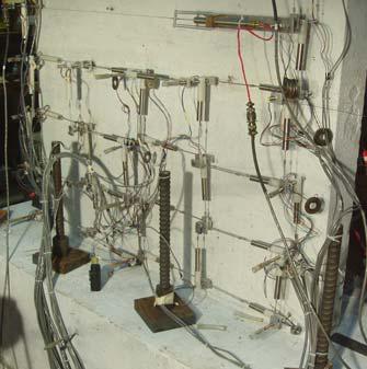
42 Test Program - Instrumentation ~ 100 Sensors (load, strain, displacement) West Face Instrumentation (flexural deformations) East Face Instrumentation (shear and anchorage deformations) Pedestal sliding and uplift measured Variation of measurements used on repeated tests 42


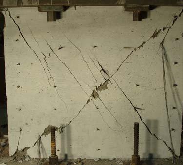
43 Test Program - Objectives # Backbone Relations # Failure mode # Influence of details Jamb bars No hooks No Hoops/Ties Axial load failure 43
! Satisfaction, but ultimately, it s about 44")
44 FEMA 356 Section 2.8 Alternative modeling parameters and acceptance criteria! Experimental setup! Data reduction and reporting! Design parameters and acceptance criteria Observations! For the right owner/building, can be highly productive process! Caveats (uncertainty, surprises, etc)! Satisfaction, but ultimately, it s about 44
: Smooth backbone curve shall be drawn through the intersection of the first cycle curve for the (i)th deformation step with the second cycle")
45 FEMA 356 Backbone Curves 2.8.3(1.2): Smooth backbone curve shall be drawn through the intersection of the first cycle curve for the (i)th deformation step with the second cycle curve of the (i-1)the deformation step, for all i steps. Force Backbone curve Deformation FEMA 356 Figure
46 FEMA (1.2) Approach 100 Resulting backbone curve applying 2.8.3(1.2) was suspect
47 Test-Derived Backbone Curves 100 Yield Strength degradation Load Crack 50 Residual Displacement 47


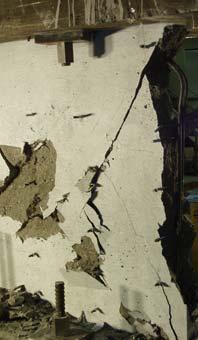
48 Test Photos ~5% Axial Load Yield level 3 x Yield Axial collapse 48

49 Axial Failure 49
50 Initial Stiffness: Pier test: P=0.05A g f c ~0.6V n Pre-cracked response (0.4E) Lateral Load Shear Experimental Flexure model/test Slip contribution flex-model shear-model total-exp flex-exp shear-exp Lateral Displacement 0.4E c is reasonable for uncracked shear stiffness Flexural stiffness appears impacted by slip. 50
51 Deformations Flexure/Shear Same Scale Lateral Load flex-exp shear-exp shear-envelope Lateral Displacement Flexural deformations are essentially elastic, nonlinear shear 51
52 Test Derived Backbone Relations (Pier) ~150%V n FEMA FEMA 356 Default Lateral Load Axial load collapse top disp.-exp shear-envelope shear-backbone shear- backbone (+) shear- backbone (-) shear- backbone (avg) 2% Lateral Displacement 1% Not as stiff in the post-cracked range as FEMA relation Post-cracked stiffness ~1/10 to 1/20 of the initial stiffness Peak strength (85 to 175%) of V n Consistent with prior tests Less pronounced strength degradation, less residual strength Deformation capacity > FEMA at initiation of strength degradation 52
53 Presentation Overview FEMA 356 Requirements P-M-V Modeling Preliminary test results Axial load modeling 53
54 Axial Capacity Model Shear Friciton d c M P V s h V d = dowel force A tr f st = force in horizontal steel P s = force in vertical steel V sf = force due to shear friction N = normal force B A tr f st h V d V sf N s v V P d P S c sin B ' Vsf cosb ( Ast f st tan ( nbars, webvd, web ( sv d c B ( Vsf sinb Ps, web ( nbars, boundary Ps, boundary sh ( N B ' N cos ( n n bars, boundary bars, web P V s, web d, boundary 54
55 55 Axial Capacity Model Axial capacity (Equilibrium and shear friction) Shear friction vs drift at axial failure Drift at axial failure (column test data) C ( ' m m v yt s m s h f A P F B B F tan tan 1 / ( C ( ( ' B B B tan / tan / ) tan ( v yt st v yt st Axial s h f A P C C s h f A P C L " 0 2 1, " C ' Axial m h C C F
56 Shear Friction - Columns F m C 1 =2.1445; C 2 =25; V r =0 Flexure test data C 1 =1.6; C 2 =3.125; V r =0 Shear test data: 0.5 F m ' C C 2 " 3 1 C24 5, 6 h 7 Axial Drift Axial Failure 56
57 Influence of Pier Geometry Shear crack plane B h B Column B l l l h/l = ½ (B=26.6 ) h/l = 1 (B=45 ) h/l = 2 (B=63.4 )! Assumed to extend full pier height, from corner-tocorner 57
58 Axial Capacity Model Wall Piers 0.12 (Astfyth/sv)/P F m = ("/h) B=65 P/P 0 =0.10 B=45 P/P 0 =0.10 B=25 P/P 0 =0.10 B=65 P/P 0 =0.05 B=45 P/P 0 =0.05 B=25 P/P 0 =0.05 B'@G Typical range for Lightly-reinforced pier B'HG B'EG Pier Drift Ratio 58
59 Shear Friction Column Tests F m ' C 2 " 3 1 C C24 5, 6 h 7 Axial 0 F m C 1 =2.1445; C 2 =25; V r =0 Flexure test data C 1 =1.6; C 2 =3.125; V r =0 Shear test data: C 1 =1.6; C 2 =30; V r =0.01 C 1 =1.6; C 2 =50; V r = Drift Axial Failure 59
60 Axial Capacity Model Test Results 0.15 B'HG.degrees (A st f yt h/s v )/P 0 =0.025 V r =0 P/P0 0.1 (A st f yt h/s v )/P 0 =0.025 V r =0.2V n (A st f yt h/s v )/P 0 =0.015 V r =0.1V n C 1 =1.6 C 2 =30 (A st f yt h/s v )/P 0 =0.015 V r =0.1V n C 1 =1.6 C 2 =50 (A st f yt h/s v )/P 0 =0.015 V r =0.1V n C 1 =1.0 C 2 =25 Test Results Pier Drift Ratio 60
61 Lightly-Reinforced Wall Segments John Wallace University of California, Los Angeles with contributions from Mr. Leonardo Massone & Dr. Kutay Orakcal University of California, Los Angeles
62 Additional References Greifenhagen, H.; Lestuzzi, P, Static cyclic tests on lightly reinforced concrete shear walls, Engineering Structures, vol. 27, pp , Sept Palermo, D.; Vecchio, F.J., Compression field modeling of reinforced concrete subjected to reversed loading: verification, ACI Structural Journal. Vol. 101, no. 2, pp Mar.-Apr Hidalgo, Pedro A.; Ledezma, Christian A.; Jordan, Rodrigo M., Seismic behavior of squat reinforced concrete shear walls, Earthquake Spectra. Vol. 18, no. 2, pp May Hwang, Shyh-Jiann; et al., Analytical model for predicting shear strength of squat walls, Journal of Structural Engineering. Vol. 127, no. 1, pp Jan Petrangeli, Marco, Fiber element for cyclic bending and shear of RC structures, II: Verification, Journal of Engineering Mechanics. Vol. 125, no. 9, pp , Sept Salonikios, Thomas N.; et al., Cyclic load behavior of low-slenderness reinforced concrete walls: Design basis and test results, ACI Structural Journal. Vol. 96, no. 4, pp July-Aug Salonikios, Thomas N.; et al., Cyclic load behavior of low-slenderness reinforced concrete walls: Failure Modes, Strength and Deformation Analysis, and design Implications, ACI Structural Journal. Vol. 97, no. 1, pp Jan.-Feb Kappos, A. J.; Salonikios, T. N., Premature sliding shear failure in squat shear walls: fact or myth? Proceedings of the Second Japan-UK Workshop on Implications of Recent, Earthquakes on Seismic Risk; pp Saatcioglu, M.; Wiradinata, S., The effect of aspect ratio on seismic resistance of squat shear walls, Proceedings of the 8th European Conference on Earthquake Engineering; pp. 7.3/ Wiradinata, Sanusi, Behaviour of squat walls subjected to load reversals, Dept. of Civil Engineering, University of Toronto, pp. Paulay, T.; Priestley, M. J. N.; Synge, A. J., Ductility in earthquake resisting squat shearwalls, Journal of the American Concrete Institute. Vol. 79, no. 4, pp July-Aug Lefas, et al., Behavior of RC Structural Walls: Strength, Deformation Characteristics, and Failure Mechanism, ACI Structural Journal, 87(1), pp , Jan Feb Saatcioglu, M., Hysteretic Shear Response of Low-Rise Walls, Concrete Shear in Earthquake, Elsevier Applied Science, New York, New York, pp Bold, underlined: Test results presented 62
Wall Modeling & Behavior
 Wall Modeling & Behavior John Wallace University of California, Los Angeles with contributions from Mr. Leonardo Massone & Dr. Kutay Orakcal University of California, Los Angeles Presentation Overview
Behavior and Modeling of Existing Reinforced Concrete Columns
 Behavior and Modeling of Existing Reinforced Concrete Columns Kenneth J. Elwood University of British Columbia with contributions from Jose Pincheira, Univ of Wisconsin John Wallace, UCLA Questions? What
PACIFIC EARTHQUAKE ENGINEERING RESEARCH CENTER
 PACIFIC EARTHQUAKE ENGINEERING RESEARCH CENTER Shear-Flexure Interaction Modeling for Reinforced Concrete Structural Walls and Columns under Reversed Cyclic Loading Kristijan Kolozvari Department of Civil
Finite Element Modelling with Plastic Hinges
 01/02/2016 Marco Donà Finite Element Modelling with Plastic Hinges 1 Plastic hinge approach A plastic hinge represents a concentrated post-yield behaviour in one or more degrees of freedom. Hinges only
SEISMIC PERFORMANCE OF LARGE RC CIRCULAR HOLLOW COLUMNS
 SEISMIC PERFORMANCE OF LARGE RC CIRCULAR HOLLOW COLUMNS Giulio RANZO 1 And M J N PRIESTLEY SUMMARY experimental study conducted on three large size specimens are reported. The test units, designed with
Shear Failure Model for Flexure-Shear Critical Reinforced Concrete Columns
 Shear Failure Model for Flexure-Shear Critical Reinforced Concrete Columns W.M. Ghannoum 1 and J.P. Moehle 2 1 Assistant Professor, Dept. of Civil, Architectural, and Environmental Engineering, University
Seismic Pushover Analysis Using AASHTO Guide Specifications for LRFD Seismic Bridge Design
 Seismic Pushover Analysis Using AASHTO Guide Specifications for LRFD Seismic Bridge Design Elmer E. Marx, Alaska Department of Transportation and Public Facilities Michael Keever, California Department
PEER/SSC Tall Building Design. Case study #2
 PEER/SSC Tall Building Design Case study #2 Typical Plan View at Ground Floor and Below Typical Plan View at 2 nd Floor and Above Code Design Code Design Shear Wall properties Shear wall thickness and
Prediction of the Lateral Load Displacement Curves for RC Squat Walls Failing in Shear
 PESDES 2017 International Workshop on Performance-Based Seismic Design of Structures Prediction of the Lateral Load Displacement Curves for RC Squat Walls Failing in Shear Shyh-Jiann Hang Director National
ENERGY DIAGRAM w/ HYSTERETIC
 ENERGY DIAGRAM ENERGY DIAGRAM w/ HYSTERETIC IMPLIED NONLINEAR BEHAVIOR STEEL STRESS STRAIN RELATIONSHIPS INELASTIC WORK DONE HYSTERETIC BEHAVIOR MOMENT ROTATION RELATIONSHIP IDEALIZED MOMENT ROTATION DUCTILITY
Design of a Multi-Storied RC Building
 Design of a Multi-Storied RC Building 16 14 14 3 C 1 B 1 C 2 B 2 C 3 B 3 C 4 13 B 15 (S 1 ) B 16 (S 2 ) B 17 (S 3 ) B 18 7 B 4 B 5 B 6 B 7 C 5 C 6 C 7 C 8 C 9 7 B 20 B 22 14 B 19 (S 4 ) C 10 C 11 B 23
POST-PEAK BEHAVIOR OF FRP-JACKETED REINFORCED CONCRETE COLUMNS
 POST-PEAK BEHAVIOR OF FRP-JACKETED REINFORCED CONCRETE COLUMNS - Technical Paper - Tidarut JIRAWATTANASOMKUL *1, Dawei ZHANG *2 and Tamon UEDA *3 ABSTRACT The objective of this study is to propose a new
EDEM DISCRETIZATION (Phase II) Normal Direction Structure Idealization Tangential Direction Pore spring Contact spring SPRING TYPES Inner edge Inner d
 Normal Direction Structure Idealization Tangential Direction Pore spring Contact spring SPRING TYPES Inner edge Inner d") Institute of Industrial Science, University of Tokyo Bulletin of ERS, No. 48 (5) A TWO-PHASE SIMPLIFIED COLLAPSE ANALYSIS OF RC BUILDINGS PHASE : SPRING NETWORK PHASE Shanthanu RAJASEKHARAN, Muneyoshi
Institute of Industrial Science, University of Tokyo Bulletin of ERS, No. 48 (5) A TWO-PHASE SIMPLIFIED COLLAPSE ANALYSIS OF RC BUILDINGS PHASE : SPRING NETWORK PHASE Shanthanu RAJASEKHARAN, Muneyoshi
Nonlinear static analysis PUSHOVER
 Nonlinear static analysis PUSHOVER Adrian DOGARIU European Erasmus Mundus Master Course Sustainable Constructions under Natural Hazards and Catastrophic Events 520121-1-2011-1-CZ-ERA MUNDUS-EMMC Structural
Sabah Shawkat Cabinet of Structural Engineering Walls carrying vertical loads should be designed as columns. Basically walls are designed in
 Sabah Shawkat Cabinet of Structural Engineering 17 3.6 Shear walls Walls carrying vertical loads should be designed as columns. Basically walls are designed in the same manner as columns, but there are
Constitutive Modeling of Reinforced Concrete Panel Behavior under Cyclic Loading
 Constitutive Modeling of Reinforced Concrete Panel Behavior under Cyclic Loading K. Orakcal & D. Ulugtekin Bogazici University, Istanbul, Turkey L. M. Massone University of Chile, Santiago, Chile SUMMARY:
Lap splice length and details of column longitudinal reinforcement at plastic hinge region
 Lap length and details of column longitudinal reinforcement at plastic hinge region Hong-Gun Park 1) and Chul-Goo Kim 2) 1), 2 Department of Architecture and Architectural Engineering, Seoul National University,
SEISMIC PERFORMANCE OF CONCRETE COLUMNS WITH INADEQUATE TRANSVERSE REINFORCEMENT. Alistair Boys 1 Des K. Bull 2 Stefano Pampanin 3 ABSTRACT
 SEISMIC PERFORMANCE OF CONCRETE COLUMNS WITH INADEQUATE TRANSVERSE REINFORCEMENT. Alistair Boys 1 Des K. Bull 2 Stefano Pampanin 3 ABSTRACT Existing New Zealand building stock contains a significant number
Earthquake-resistant design of indeterminate reinforced-concrete slender column elements
 Engineering Structures 29 (2007) 163 175 www.elsevier.com/locate/engstruct Earthquake-resistant design of indeterminate reinforced-concrete slender column elements Gerasimos M. Kotsovos a, Christos Zeris
Seismic Assessment of a RC Building according to FEMA 356 and Eurocode 8
 1 Seismic Assessment of a RC Building according to FEMA 356 and Eurocode 8 Ioannis P. GIANNOPOULOS 1 Key words: Pushover analysis, FEMA 356, Eurocode 8, seismic assessment, plastic rotation, limit states
Influence of column web stiffening on the seismic behaviour of beam-tocolumn
 Influence of column web stiffening on the seismic behaviour of beam-tocolumn joints A.L. Ciutina & D. Dubina The Politehnica University of Timisoara, Romania ABSTRACT: The present paper summarises the
EUROCODE EN SEISMIC DESIGN OF BRIDGES
 Brussels, 18-20 February 2008 Dissemination of information workshop 1 EUROCODE EN1998-2 SEISMIC DESIGN OF BRIDGES Basil Kolias Basic Requirements Brussels, 18-20 February 2008 Dissemination of information
DEFORMATION CAPACITY OF OLDER RC SHEAR WALLS: EXPERIMENTAL ASSESSMENT AND COMPARISON WITH EUROCODE 8 - PART 3 PROVISIONS
 DEFORMATION CAPACITY OF OLDER RC SHEAR WALLS: EXPERIMENTAL ASSESSMENT AND COMPARISON WITH EUROCODE 8 - PART 3 PROVISIONS Konstantinos CHRISTIDIS 1, Emmanouil VOUGIOUKAS 2 and Konstantinos TREZOS 3 ABSTRACT
City, University of London Institutional Repository
 City Research Online City, University of London Institutional Repository Citation: Mergos, P.E. & Kappos, A.J. (2012). A gradual spread inelasticity model for R/C beam-columns, accounting for flexure,
NON-LINEAR MODELING OF FLAT-PLATE SYSTEMS UNDER CYCLIC LOADING
 NON-LINEAR MODELING OF FLAT-PLATE SYSTEMS UNDER CYCLIC LOADING S. Derogar & C. Ince Yeditepe University, Turkey P. Mandal University of Manchester, UK Y. C. Toklu Bayburt University, Turkey SUMMARY: There
Chapter 8. Shear and Diagonal Tension
 Chapter 8. and Diagonal Tension 8.1. READING ASSIGNMENT Text Chapter 4; Sections 4.1-4.5 Code Chapter 11; Sections 11.1.1, 11.3, 11.5.1, 11.5.3, 11.5.4, 11.5.5.1, and 11.5.6 8.2. INTRODUCTION OF SHEAR
Appendix G Analytical Studies of Columns
 Appendix G Analytical Studies of Columns G.1 Introduction Analytical parametric studies were performed to evaluate a number of issues related to the use of ASTM A103 steel as longitudinal and transverse
Nonlinear Analysis of Reinforced Concrete Bridges under Earthquakes
 6 th International Conference on Advances in Experimental Structural Engineering 11 th International Workshop on Advanced Smart Materials and Smart Structures Technology August 1-2, 2015, University of
Lecture-04 Design of RC Members for Shear and Torsion
 Lecture-04 Design of RC Members for Shear and Torsion By: Prof. Dr. Qaisar Ali Civil Engineering Department UET Peshawar drqaisarali@uetpeshawar.edu.pk www.drqaisarali.com 1 Topics Addressed Design of
Non-linear Shear Model for R/C Piers. J. Guedes, A.V. Pinto, P. Pegon
 Non-linear Shear Model for R/C Piers J. Guedes, A.V. Pinto, P. Pegon EUR 24153 EN - 2010 The mission of the JRC-IPSC is to provide research results and to support EU policy-makers in their effort towards
Soil-Structure Interaction in Nonlinear Pushover Analysis of Frame RC Structures: Nonhomogeneous Soil Condition
 ABSTRACT: Soil-Structure Interaction in Nonlinear Pushover Analysis of Frame RC Structures: Nonhomogeneous Soil Condition G. Dok ve O. Kırtel Res. Assist., Department of Civil Engineering, Sakarya University,
Design of Reinforced Concrete Beam for Shear
 Lecture 06 Design of Reinforced Concrete Beam for Shear By: Civil Engineering Department UET Peshawar drqaisarali@uetpeshawar.edu.pk Topics Addressed Shear Stresses in Rectangular Beams Diagonal Tension
Design of Reinforced Concrete Beam for Shear
 Lecture 06 Design of Reinforced Concrete Beam for Shear By: Prof Dr. Qaisar Ali Civil Engineering Department UET Peshawar drqaisarali@uetpeshawar.edu.pk 1 Topics Addressed Shear Stresses in Rectangular
An Investigation on the Correlation of Inter-story Drift and Performance Objectives in Conventional RC Frames
 Available online at www.ijournalse.org Emerging Science Journal Vol., No. 3, June, 18 An Investigation on the Correlation of Inter-story Drift and Performance Objectives in Conventional RC Frames Saeed
CHAPTER 5. T a = 0.03 (180) 0.75 = 1.47 sec 5.12 Steel moment frame. h n = = 260 ft. T a = (260) 0.80 = 2.39 sec. Question No.
 0.75 = 1.47 sec 5.12 Steel moment frame. h n = = 260 ft. T a = (260) 0.80 = 2.39 sec. Question No.") CHAPTER 5 Question Brief Explanation No. 5.1 From Fig. IBC 1613.5(3) and (4) enlarged region 1 (ASCE 7 Fig. -3 and -4) S S = 1.5g, and S 1 = 0.6g. The g term is already factored in the equations, thus
CHAPTER 5 Question Brief Explanation No. 5.1 From Fig. IBC 1613.5(3) and (4) enlarged region 1 (ASCE 7 Fig. -3 and -4) S S = 1.5g, and S 1 = 0.6g. The g term is already factored in the equations, thus
This Technical Note describes how the program checks column capacity or designs reinforced concrete columns when the ACI code is selected.
 COMPUTERS AND STRUCTURES, INC., BERKELEY, CALIFORNIA DECEMBER 2001 CONCRETE FRAME DESIGN ACI-318-99 Technical Note This Technical Note describes how the program checks column capacity or designs reinforced
PHAETHON: Software for Analysis of Shear-Critical Reinforced Concrete Columns
 Modern Applied Science; Vol. 12, No. 3; 218 ISSN 1913-1844 E-ISSN 1913-1852 Published by Canadian Center of Science and Education PHAETHON: Software for Analysis of Shear-Critical Reinforced Concrete Columns
Mechanical Properties of Materials
 Mechanical Properties of Materials Strains Material Model Stresses Learning objectives Understand the qualitative and quantitative description of mechanical properties of materials. Learn the logic of
INFLUENCE OF FLANGE STIFFNESS ON DUCTILITY BEHAVIOUR OF PLATE GIRDER
 International Journal of Civil Structural 6 Environmental And Infrastructure Engineering Research Vol.1, Issue.1 (2011) 1-15 TJPRC Pvt. Ltd.,. INFLUENCE OF FLANGE STIFFNESS ON DUCTILITY BEHAVIOUR OF PLATE
New model for Shear Failure of R/C Beam-Column Joints. Hitoshi Shiohara
 New model for Shear Failure of R/ Beam-olumn Joints Hitoshi Shiohara Dept. of Architectural Engineering, The University of Tokyo, Tokyo 3-8656, Japan; PH +8(3)584-659; FAX+8(3)584-656; email:shiohara@arch.t.u-tokyo.ac.jp
COLUMNS: BUCKLING (DIFFERENT ENDS)
") COLUMNS: BUCKLING (DIFFERENT ENDS) Buckling of Long Straight Columns Example 4 Slide No. 1 A simple pin-connected truss is loaded and supported as shown in Fig. 1. All members of the truss are WT10 43
COLUMNS: BUCKLING (DIFFERENT ENDS) Buckling of Long Straight Columns Example 4 Slide No. 1 A simple pin-connected truss is loaded and supported as shown in Fig. 1. All members of the truss are WT10 43
EFFECT OF SHEAR REINFORCEMENT ON FAILURE MODE OF RC BRIDGE PIERS SUBJECTED TO STRONG EARTHQUAKE MOTIONS
 EFFECT OF SHEAR REINFORCEMENT ON FAILURE MODE OF RC BRIDGE PIERS SUBJECTED TO STRONG EARTHQUAKE MOTIONS Atsuhiko MACHIDA And Khairy H ABDELKAREEM SUMMARY Nonlinear D FEM was utilized to carry out inelastic
Pushover Seismic Analysis of Bridge Structures
 Pushover Seismic Analysis of Bridge Structures Bernardo Frère Departamento de Engenharia Civil, Arquitectura e Georrecursos, Instituto Superior Técnico, Technical University of Lisbon, Portugal October
Flexure: Behavior and Nominal Strength of Beam Sections
 4 5000 4000 (increased d ) (increased f (increased A s or f y ) c or b) Flexure: Behavior and Nominal Strength of Beam Sections Moment (kip-in.) 3000 2000 1000 0 0 (basic) (A s 0.5A s ) 0.0005 0.001 0.0015
Chapter 4. Test results and discussion. 4.1 Introduction to Experimental Results
 Chapter 4 Test results and discussion This chapter presents a discussion of the results obtained from eighteen beam specimens tested at the Structural Technology Laboratory of the Technical University
CAPACITY SPECTRUM FOR STRUCTURES ASYMMETRIC IN PLAN
 13 th World Conference on Earthquake Engineering Vancouver, B.C., Canada August 1-6, 004 Paper No. 653 CAPACITY SPECTRUM FOR STRUCTURES ASYMMETRIC IN PLAN B. K. Raghu Prasad 1, A. Seetha Ramaiah and A.
Seismic performance evaluation of existing RC buildings designed as per past codes of practice
 Sādhanā Vol. 37, Part 2, April 2012, pp. 281 297. c Indian Academy of Sciences Seismic performance evaluation of existing RC buildings designed as per past codes of practice 1. Introduction K RAMA RAJU,
Journey Through a Project: Shake-table Test of a Reinforced Masonry Structure
 Journey Through a Project: Shake-table Test of a Reinforced Masonry Structure P. Benson Shing and Andreas Koutras Department of Structural Engineering University of California, San Diego NHERI @ UCSD Workshop,
Non-Linear Modeling of Reinforced Concrete Structures for Seismic Applications
 2/18/21 Non-Linear Modeling of Reinforced Concrete Structures for Seismic Applications Luis A. Montejo Assistant Professor Department of Engineering Science and Materials University of Puerto Rico at Mayaguez
MODELING OF NONLINEAR BEHAVIOR OF RC SHEAR WALLS UNDER COMBINED AXIAL, SHEAR AND FLEXURAL LOADING
 CD02-003 MODELING OF NONLINEAR BEHAVIOR OF RC SHEAR WALLS UNDER COMBINED AXIAL, SHEAR AND FLEXURAL LOADING B. Ghiassi 1, M. Soltani 2, A. A. Tasnimi 3 1 M.Sc. Student, School of Engineering, Tarbiat Modares
Lecture-08 Gravity Load Analysis of RC Structures
 Lecture-08 Gravity Load Analysis of RC Structures By: Prof Dr. Qaisar Ali Civil Engineering Department UET Peshawar www.drqaisarali.com 1 Contents Analysis Approaches Point of Inflection Method Equivalent
Sensitivity and Reliability Analysis of Nonlinear Frame Structures
 Sensitivity and Reliability Analysis of Nonlinear Frame Structures Michael H. Scott Associate Professor School of Civil and Construction Engineering Applied Mathematics and Computation Seminar April 8,
INELASTIC SEISMIC DISPLACEMENT RESPONSE PREDICTION OF MDOF SYSTEMS BY EQUIVALENT LINEARIZATION
 INEASTIC SEISMIC DISPACEMENT RESPONSE PREDICTION OF MDOF SYSTEMS BY EQUIVAENT INEARIZATION M. S. Günay 1 and H. Sucuoğlu 1 Research Assistant, Dept. of Civil Engineering, Middle East Technical University,
OS MODELER - EXAMPLES OF APPLICATION Version 1.0. (Draft)
") OS MODELER - EXAMPLES OF APPLICATION Version 1.0 (Draft) Matjaž Dolšek February 2008 Content 1. Introduction... 1 2. Four-storey reinforced concrete frame designed according to EC8... 2 2.1. Description
OS MODELER - EXAMPLES OF APPLICATION Version 1.0 (Draft) Matjaž Dolšek February 2008 Content 1. Introduction... 1 2. Four-storey reinforced concrete frame designed according to EC8... 2 2.1. Description
NUMERICAL SIMULATION OF THE INELASTIC SEISMIC RESPONSE OF RC STRUCTURES WITH ENERGY DISSIPATORS
 NUMERICAL SIMULATION OF THE INELASTIC SEISMIC RESPONSE OF RC STRUCTURES WITH ENERGY DISSIPATORS ABSTRACT : P Mata1, AH Barbat1, S Oller1, R Boroschek2 1 Technical University of Catalonia, Civil Engineering
A Modified Response Spectrum Analysis Procedure (MRSA) to Determine the Nonlinear Seismic Demands of Tall Buildings
 to Determine the Nonlinear Seismic Demands of Tall Buildings") Fawad A. Najam Pennung Warnitchai Asian Institute of Technology (AIT), Thailand Email: fawad.ahmed.najam@ait.ac.th A Modified Response Spectrum Analysis Procedure (MRSA) to Determine the Nonlinear Seismic
Fawad A. Najam Pennung Warnitchai Asian Institute of Technology (AIT), Thailand Email: fawad.ahmed.najam@ait.ac.th A Modified Response Spectrum Analysis Procedure (MRSA) to Determine the Nonlinear Seismic
CE5510 Advanced Structural Concrete Design - Design & Detailing of Openings in RC Flexural Members-
 CE5510 Advanced Structural Concrete Design - Design & Detailing Openings in RC Flexural Members- Assoc Pr Tan Kiang Hwee Department Civil Engineering National In this lecture DEPARTMENT OF CIVIL ENGINEERING
Role of Force Resultant Interaction on Ultra-High Performance Concrete
 First International Interactive Symposium on UHPC 216 Role of Force Resultant Interaction on Ultra-High Performance Concrete Author(s) & Affiliation: Titchenda Chan (1), Kevin R. Mackie (1), and Jun Xia
EARTHQUAKE SIMULATION TESTS OF BRIDGE COLUMN MODELS DAMAGED DURING 1995 KOBE EARTHQUAKE
 EARTHQUAKE SIMULATION TESTS OF BRIDGE COLUMN MODELS DAMAGED DURING 1995 KOBE EARTHQUAKE J. Sakai 1, S. Unjoh 2 and H. Ukon 3 1 Senior Researcher, Center for Advanced Engineering Structural Assessment and
Coupling Beams of Shear Walls
 Coupling Beams of Shear Walls Modelling Procedure for the Seismic Analysis of RC Structures João Miguel Damião Bezelga (1) July 215 (1) Instituto Superior Técnico Universidade de Lisboa, Av. Rovisco Pais,
A q u a b l u e a t t h e G o l d e n M i l e
 A q u a b l u e a t t h e G o l d e n M i l e H a t o R e y, P u e r t o R i c o G e n e r a l B u i l d i n g I n f o r m a t i o n Building Facts: 7-story parking structure + luxury apartments 900,000
Lecture-03 Design of Reinforced Concrete Members for Flexure and Axial Loads
 Lecture-03 Design of Reinforced Concrete Members for Flexure and Axial Loads By: Prof. Dr. Qaisar Ali Civil Engineering Department UET Peshawar drqaisarali@uetpeshawar.edu.pk www.drqaisarali.com Prof.
[5] Stress and Strain
![[5] Stress and Strain](/thumbs/95/123344550.jpg "[5] Stress and Strain") [5] Stress and Strain Page 1 of 34 [5] Stress and Strain [5.1] Internal Stress of Solids [5.2] Design of Simple Connections (will not be covered in class) [5.3] Deformation and Strain [5.4] Hooke s Law
[5] Stress and Strain Page 1 of 34 [5] Stress and Strain [5.1] Internal Stress of Solids [5.2] Design of Simple Connections (will not be covered in class) [5.3] Deformation and Strain [5.4] Hooke s Law
Displacement-based methods EDCE: Civil and Environmental Engineering CIVIL Advanced Earthquake Engineering
 Displacement-based methods EDCE: Civil and Environmental Engineering CIVIL 706 - Advanced Earthquake Engineering EDCE-EPFL-ENAC-SGC 2016-1- Content! Link to force-based methods! Assumptions! Reinforced
Earthquake Simulation Tests on a 1:5 Scale 10 - Story RC Residential Building Model
 Earthquake Simulation Tests on a 1:5 Scale 1 - Story RC Residential Building Model H. S. Lee, S. J. Hwang, K. B. Lee, & C. B. Kang Korea University, Seoul, Republic of Korea S. H. Lee & S. H. Oh Pusan
AXIAL COLLAPSE OF REINFORCED CONCRETE COLUMNS
 3 th World Conference on Earthquake Engineering Vancouver, B.C., Canada August -6, 4 Paper No. 699 AXIAL COLLAPSE OF REINFORCED CONCRETE COLUMNS Manabu YOSHIMURA, Yoshikazu TAKAINE and Takaya NAKAMURA
DETERMINATION OF DUCTILITY CAPACITY AND OTHER SECTION PROPERTIES OF T-SHAPED RC WALLS IN DIRECT DISPLACEMENT-BASED DESIGN
 DETERMINATION OF DUCTILITY CAPACITY AND OTHER SECTION PROPERTIES OF T-SHAPED RC WALLS IN DIRECT DISPLACEMENT-BASED DESIGN E. Smyrou 1, T.J. Sullivan 2, M.J.N. Priestley 3 and G.M. Calvi 4 1 PhD Candidate,
PLATE GIRDERS II. Load. Web plate Welds A Longitudinal elevation. Fig. 1 A typical Plate Girder
 16 PLATE GIRDERS II 1.0 INTRODUCTION This chapter describes the current practice for the design of plate girders adopting meaningful simplifications of the equations derived in the chapter on Plate Girders
Seismic design of bridges
 NATIONAL TECHNICAL UNIVERSITY OF ATHENS LABORATORY FOR EARTHQUAKE ENGINEERING Seismic design of bridges Lecture 3 Ioannis N. Psycharis Capacity design Purpose To design structures of ductile behaviour
This document is downloaded from DR-NTU, Nanyang Technological University Library, Singapore.
 This document is downloaded from DR-NTU, Nanyang Technological University Library, Singapore. Title Truss Model for Shear Strength of Structural Concrete Walls Author(s) Citation Chandra, Jimmy; Chanthabouala,
SIMPLIFIED METHOD FOR PREDICTING DEFORMATIONS OF RC FRAMES DURING FIRE EXPOSURE
 SIMPLIFIED METHOD FOR PREDICTING DEFORMATIONS OF RC FRAMES DURING FIRE EXPOSURE M.A. Youssef a, S.F. El-Fitiany a a Western University, Faculty of Engineering, London, Ontario, Canada Abstract Structural
COLUMN BASE WEAK AXIS ALIGNED ASYMMETRIC FRICTION CONNECTION CYCLIC PERFORMANCE
 8 th International Conference on Behavior of Steel Structures in Seismic Areas Shanghai, China, July 1-3, 2015 COLUMN BASE WEAK AXIS ALIGNED ASYMMETRIC FRICTION CONNECTION CYCLIC PERFORMANCE J. Borzouie*,
City, University of London Institutional Repository
 City Research Online City, University of London Institutional Repository Citation: Mergos, P.E. & Beyer, K. (214). Modelling shear-flexure interaction in equivalent frame models of slender reinforced concrete
Comparison of Structural Models for Seismic Analysis of Multi-Storey Frame Buildings
 Comparison of Structural Models for Seismic Analysis of Multi-Storey Frame Buildings Dj. Ladjinovic, A. Raseta, A. Radujkovic & R. Folic University of Novi Sad, Faculty of Technical Sciences, Novi Sad,
Inelastic shear response of RC coupled structural walls
 Inelastic shear response of RC coupled structural walls E. Morariu EDIT Structural, Bucuresti, Rumania. T. Isakovic, N. Eser & M. Fischinger Faculty of Civil and Geodetic Engineering, University of Ljubljana,
Supplement: Statically Indeterminate Frames
 : Statically Indeterminate Frames Approximate Analysis - In this supplement, we consider another approximate method of solving statically indeterminate frames subjected to lateral loads known as the. Like
STATIC NONLINEAR ANALYSIS. Advanced Earthquake Engineering CIVIL-706. Instructor: Lorenzo DIANA, PhD
 STATIC NONLINEAR ANALYSIS Advanced Earthquake Engineering CIVIL-706 Instructor: Lorenzo DIANA, PhD 1 By the end of today s course You will be able to answer: What are NSA advantages over other structural
Dynamic Analysis of a Reinforced Concrete Structure Using Plasticity and Interface Damage Models
 Dynamic Analysis of a Reinforced Concrete Structure Using Plasticity and Interface Damage Models I. Rhee, K.J. Willam, B.P. Shing, University of Colorado at Boulder ABSTRACT: This paper examines the global
SHOTCRETE OR FRP JACKETING OF CONCRETE COLUMNS FOR SEISMIC RETROFITTING
 SfP PROJECT 9773: SEISMIC ASSESSMENT AND REHABILITATION OF EXISTING BUILDINGS INTERNATIONAL CLOSING WORKSHOP ISTANBUL, 3 MAY-JUNE, 5 SHOTCRETE OR FRP JACKETING OF CONCRETE COLUMNS FOR SEISMIC RETROFITTING
Concrete contribution to initial shear strength of RC hollow bridge columns
 Structural Engineering and Mechanics, Vol. 41, No. 1 (2012) 43-65 43 Concrete contribution to initial shear strength of RC hollow bridge columns Ick-Hyun Kim 1a, Chang-Ho Sun 1b and Myoungsu Shin 2 * 1
Supplement: Statically Indeterminate Trusses and Frames
 : Statically Indeterminate Trusses and Frames Approximate Analysis - In this supplement, we consider an approximate method of solving statically indeterminate trusses and frames subjected to lateral loads
999 TOWN & COUNTRY ROAD ORANGE, CALIFORNIA TITLE PUSHOVER ANALYSIS EXAMPLE BY R. MATTHEWS DATE 5/21/01
 DESCRIPTION Nonlinear static (pushover) analysis will be performed on a railroad bridge bent using several methods to determine its ultimate lateral deflection capability. 1. SAP2000 Nonlinear with axial-moment
INFLUENCE OF LOADING RATIO ON QUANTIFIED VISIBLE DAMAGES OF R/C STRUCTURAL MEMBERS
 Paper N 1458 Registration Code: S-H1463506048 INFLUENCE OF LOADING RATIO ON QUANTIFIED VISIBLE DAMAGES OF R/C STRUCTURAL MEMBERS N. Takahashi (1) (1) Associate Professor, Tohoku University, ntaka@archi.tohoku.ac.jp
five Mechanics of Materials 1 ARCHITECTURAL STRUCTURES: FORM, BEHAVIOR, AND DESIGN DR. ANNE NICHOLS SUMMER 2017 lecture
 ARCHITECTURAL STRUCTURES: FORM, BEHAVIOR, AND DESIGN DR. ANNE NICHOLS SUMMER 2017 lecture five mechanics www.carttalk.com of materials Mechanics of Materials 1 Mechanics of Materials MECHANICS MATERIALS
A. Belejo, R. Bento & C. Bhatt Instituto Superior Técnico, Lisbon, Portugal 1.INTRODUCTION
 Comparison of different computer programs to predict the seismic performance of SPEAR the SPEAR building building by means of by means of Pushover Analysis A. Belejo, R. Bento & C. Bhatt Instituto Superior
Chord rotation demand for Effective Catenary Action under Monotonic. Loadings
 ICCM015, 14-17 th July, Auckland, NZ Chord rotation demand for Effective Catenary Action under Monotonic Loadings *Meng-Hao Tsai Department of Civil Engineering, National Pingtung University of Science
On The Ultimate Strength of RC Shear Wall under Multi-Axes Seismic Loading Condition
 On The Ultimate Strength of RC Shear Wall under Multi-Axes Seismic Loading Condition KITADA Yoshio JNES (Japan Nuclear Energy Safety Organization), Tokyo, Japan 0 BACKGROUND AND PURPOSES OF THE STUDY There
RETAINING WALL LOADS: Horizontal Equivalent Fluid Pressure = pcf. (Load Case = Soil)
") QuickWall 8.0 - RETAINING WALL ANALYSIS AND DESIGN ================================================================================ Job ID : Job Description : Designed By : ================================================================================
QuickWall 8.0 - RETAINING WALL ANALYSIS AND DESIGN ================================================================================ Job ID : Job Description : Designed By : ================================================================================
ε t increases from the compressioncontrolled Figure 9.15: Adjusted interaction diagram
 CHAPTER NINE COLUMNS 4 b. The modified axial strength in compression is reduced to account for accidental eccentricity. The magnitude of axial force evaluated in step (a) is multiplied by 0.80 in case
Experimental investigation on monotonic performance of steel curved knee braces for weld-free beam-to-column connections
 Experimental investigation on monotonic performance of steel curved knee braces for weld-free beam-to-column connections *Zeyu Zhou 1) Bo Ye 2) and Yiyi Chen 3) 1), 2), 3) State Key Laboratory of Disaster
[8] Bending and Shear Loading of Beams
![[8] Bending and Shear Loading of Beams](/thumbs/92/110949676.jpg "[8] Bending and Shear Loading of Beams") [8] Bending and Shear Loading of Beams Page 1 of 28 [8] Bending and Shear Loading of Beams [8.1] Bending of Beams (will not be covered in class) [8.2] Bending Strain and Stress [8.3] Shear in Straight
[8] Bending and Shear Loading of Beams Page 1 of 28 [8] Bending and Shear Loading of Beams [8.1] Bending of Beams (will not be covered in class) [8.2] Bending Strain and Stress [8.3] Shear in Straight
Limit analysis of brick masonry shear walls with openings under later loads by rigid block modeling
 Limit analysis of brick masonry shear walls with openings under later loads by rigid block modeling F. Portioli, L. Cascini, R. Landolfo University of Naples Federico II, Italy P. Foraboschi IUAV University,
Design of Reinforced Concrete Structures (II)
") Design of Reinforced Concrete Structures (II) Discussion Eng. Mohammed R. Kuheil Review The thickness of one-way ribbed slabs After finding the value of total load (Dead and live loads), the elements are
Design of Reinforced Concrete Structures (II) Discussion Eng. Mohammed R. Kuheil Review The thickness of one-way ribbed slabs After finding the value of total load (Dead and live loads), the elements are
3.5 Reinforced Concrete Section Properties
 CHAPER 3: Reinforced Concrete Slabs and Beams 3.5 Reinforced Concrete Section Properties Description his application calculates gross section moment of inertia neglecting reinforcement, moment of inertia
SeismoBuild Verification Report (KANEPE) For version 2018
 For version 2018") SeismoBuild Verification Report (KANEPE) For version 2018 Copyright Copyright 2002-2018 Seismosoft Ltd. All rights reserved. SeismoBuild is a registered trademark of Seismosoft Ltd. Copyright law protects
SeismoBuild Verification Report (KANEPE) For version 2018 Copyright Copyright 2002-2018 Seismosoft Ltd. All rights reserved. SeismoBuild is a registered trademark of Seismosoft Ltd. Copyright law protects
EFFECTS OF CONFINED CONCRETE MODELS ON SIMULATING RC COLUMNS UNDER LOW-CYCLIC LOADING
 13 th World Conference on Earthquake Engineering Vancouver, B.C., Canada August 1-6, 2004 Paper No. 1498 EFFECTS OF CONFINED CONCRETE MODELS ON SIMULATING RC COLUMNS UNDER LOW-CYCLIC LOADING Zongming HUANG
M.S Comprehensive Examination Analysis
 UNIVERSITY OF CALIFORNIA, BERKELEY Spring Semester 2014 Dept. of Civil and Environmental Engineering Structural Engineering, Mechanics and Materials Name:......................................... M.S Comprehensive
Multi Linear Elastic and Plastic Link in SAP2000
 26/01/2016 Marco Donà Multi Linear Elastic and Plastic Link in SAP2000 1 General principles Link object connects two joints, i and j, separated by length L, such that specialized structural behaviour may
Junya Yazawa 1 Seiya Shimada 2 and Takumi Ito 3 ABSTRACT 1. INTRODUCTION
 PREDICTIVE METHOD OF INELASTIC RESPONSE AND RESIDUAL DEFORMATION OF STEEL FRAME USING SEMI-RIGID CONNECTIONS WITH SELF-RETURNING RESTORING FORCE CHARACTERISTICS Junya Yazawa 1 Seiya Shimada 2 and Takumi
ME Final Exam. PROBLEM NO. 4 Part A (2 points max.) M (x) y. z (neutral axis) beam cross-sec+on. 20 kip ft. 0.2 ft. 10 ft. 0.1 ft.
 M (x) y. z (neutral axis) beam cross-sec+on. 20 kip ft. 0.2 ft. 10 ft. 0.1 ft.") ME 323 - Final Exam Name December 15, 2015 Instructor (circle) PROEM NO. 4 Part A (2 points max.) Krousgrill 11:30AM-12:20PM Ghosh 2:30-3:20PM Gonzalez 12:30-1:20PM Zhao 4:30-5:20PM M (x) y 20 kip ft 0.2
ME 323 - Final Exam Name December 15, 2015 Instructor (circle) PROEM NO. 4 Part A (2 points max.) Krousgrill 11:30AM-12:20PM Ghosh 2:30-3:20PM Gonzalez 12:30-1:20PM Zhao 4:30-5:20PM M (x) y 20 kip ft 0.2