Mechatronic System Case Study: Rotary Inverted Pendulum Dynamic System Investigation
|
|
|
- Ferdinand Leonard
- 6 years ago
- Views:
Transcription

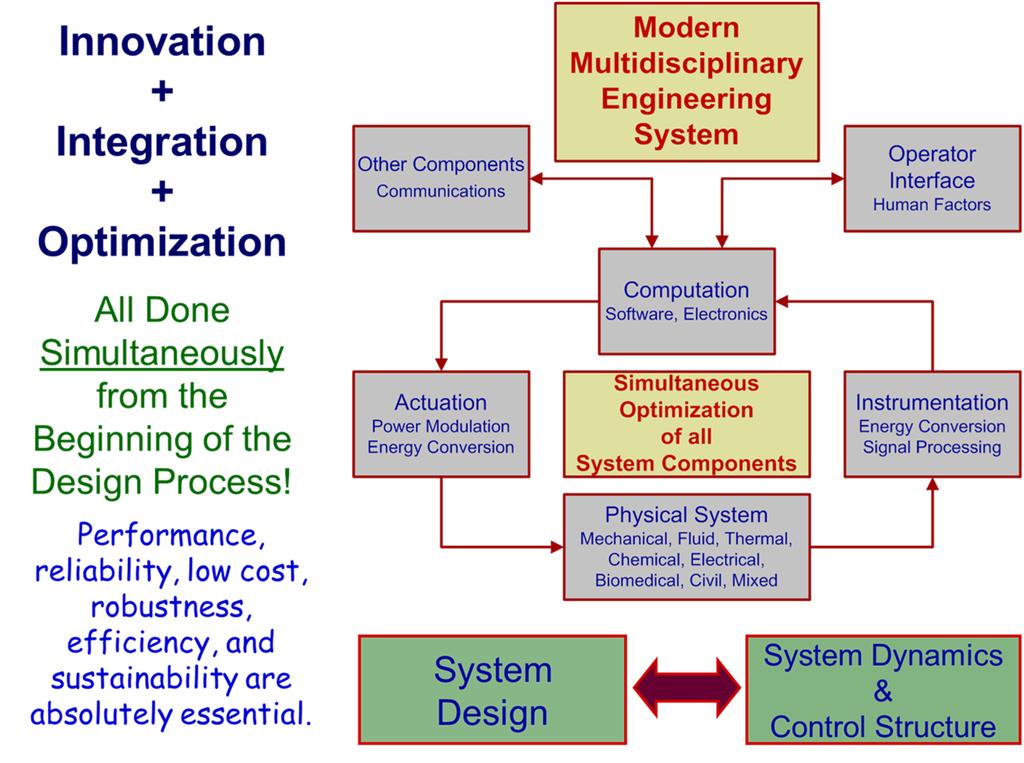
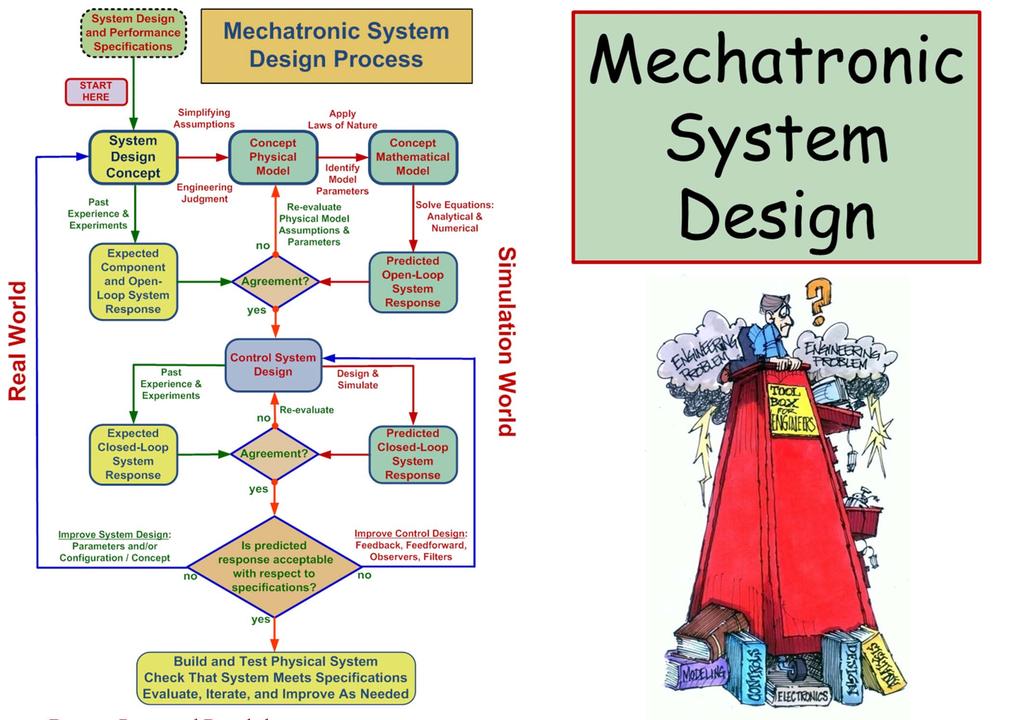
1 Mechatronic System Case Study: Rotary Inverted Pendulum Dynamic System Investigation Dr. Kevin Craig Greenheck Chair in Engineering Design & Professor of Mechanical Engineering Marquette University K. Craig 1

2 K. Craig


3 K. Craig 3

4 K. Craig 4

5 K. Craig 5


6 K. Craig 6


7 Mechatronic System Case Study: Rotary Inverted Pendulum Dynamic System Investigation Physical System K. Craig 7
8 Physical System Components Two Links Motor-driven horizontal link Un-actuated vertical pendulum link Permanent-magnet, brushed DC motor actuator 4-volt, 5-amp, DC power supply Pulse-width-modulated servo-amplifier Two rotary incremental optical encoders The resolution with quadrature decoding of each encoder is: 000 cpr (horizontal link) and 5000 cpr (pendulum) K. Craig 8
9 One encoder measures pendulum angle One encoder measures horizontal link angle Velocity data is derived for each link from the encoder data Slip-ring assembly, mounted between the housing and the motor shaft, used to connect power to the pendulum optical encoder and read the signal from the three channels of the encoder Counter-weight on the horizontal arm Leveling screws on the housing base The command to the amplifier is provided by a MatLab-based real-time control system. K. Craig 9
10 Physical Model: Simplifying Assumptions Links are rigid Two-degree-of-freedom system; generalized coordinates are: - horizontal link angle - pendulum arm angle Assume both Coulomb and viscous friction in the motor, in the slip-ring assembly, and at the pendulum revolute joint and perform tests to identify those parameters Dynamic response of the encoders is sufficiently fast that it can be considered instantaneous Dynamic response of the servo-amplifier is sufficiently fast that it can be considered instantaneous K. Craig 10
11 Motor operates in the torque mode with V in K A = i and T = K T i where: K T is the motor torque constant (N-m/A) K A is the amplifier constant (A/V) V in is the command voltage (V) T is the electromagnetic torque applied to the motor rotor (N-m) i is the motor current (A) Motor is modeled in a lumped parameter way where: J is the rotor inertia (N-m-s /rad = kg-m ) B f is the viscous friction coefficient (N-m-s/rad) T f is the Coulomb friction torque (N-m) K. Craig 11
12 Physical & Mathematical Modeling Reference Frames: R: ground xyz R 1 : arm x 1 y 1 z 1 R : pendulum x y z ˆi ˆ 1 cos sin 0 i ˆj ˆ 1 sin cos 0 j kˆ ˆ 1 k ˆi ˆ i 1 ˆj ˆ 0 cos sin j 1 kˆ 0 sin cos ˆ k 1 y 1 Top View z O B Front View y z 1 x 1 y Arm Link 1 x Pendulum Link y 1 K. Craig 1
13 Angular Velocities of Links R ˆ kˆ R 1 k Velocities of CG s of Links Point A is CG of Link 1 Point C is CG of Link R A v ˆ ˆ 11 sin i 11cos j R C v sin cos cos sin sin ˆi R cos ˆi sin ˆj kˆ ˆi ˆ 1 k1 ˆi sinˆj coskˆ R cos cos sin sin cos ˆj 1 cos kˆ K. Craig 13
14 R A v 11 R C v sin 1 cos Definitions: length of link 1 = distance from pivot O to CG of link 1 distance from CG of link 1 to end of link 1 length of link = 1 1 distance from pivot B to CG of link distance from CG of link to end of link K. Craig 14
15 Lagrange s Equations Lagrange s Equations Generalized Coordinates Kinetic Energy T of System d T T V Q dt q i q i q i q q T m v I m v R A R C 1 1 z 1 1 I I sin x I cos I sin y z xy i K. Craig 15
16 Potential Energy V of the System Generalized Forces Q TB T sgn f Q B T sgn f Equations of Motion V m g 1sin 1 B T f f T motor torque viscous damping constant joint Coulomb friction constant joint B viscous damping constant joint T Coulomb friction constant joint d T T V Q dt d T T V Q dt K. Craig 16
17 Nonlinear Equations of Motion m1 11 I1 m z 1 m 1cos I cos I 1 z sin y I m sin I m cos xy 1 1 xy 1 1 I m y 1 I cos sin T B T z f sgn m I I m sin 1 x xy 1 1 [1] m1 I I y cossin m z g 1cos B Tf sgn [] K. Craig 17
18 Define: m1 11 I1 m z 1 m 1sin I sin I 1 z cos y I m cos I m sin xy 1 1 xy 1 1 I m z 1 I cos sin T B T y f sgn m I I m cos 1 x xy 1 1 m 1 I I y cossin z mg 1sinB Tf sgn [1A] [A] K. Craig 18
19 Linearization: 0 0 Operating Point m I m I I m T B z 1 1 y xy 1 1 x xy m I I m m g B [3] [4] Definitions: [5] C1 C T B [6] C3 C C4 B C m I m I C m I 1 1 C m I C 3 1 m g 4 1 z y x xy K. Craig 19
20 Transfer Functions Cs 3 C 4 T s CC 1 3 C s CC 1 4 Cs T s CC 1 3 C s CC 1 4 (neglect damping terms): State-Space Equations (neglect damping terms): q q q q q 1 CC 4 q1 C q CC 1 3 C q CC 1 3 C q q3 0 q 4 CC 1 4 q4 C CC 1 3 C CC 1 3 C T K. Craig 0
21 Model Parameter Identification Motor Parameters Masses of Links 1 and Location of CG s of Links 1 and Moment of Inertia for Link 1: I 1z1 Inertia Matrix for Link : I I I I I I I I I x xy xz yx y yz zx zy z System Friction: Coulomb and Viscous K. Craig 1
22 Motor Parameters: Given by Manufacturer K b = 0.08; back-emf constant (V-s/rad) K t = ; torque constant (N-m/A) R = ; resistance (ohms) L = 3.3E-3; inductance (H) B m = 0; viscous damping constant (N-m-s/rad) T f = 0.014; Coulomb friction (N-m) J = 4.1E-5; inertia (kg-m ) K. Craig
23 Link Masses (experimental) Link 1 (horizontal link): kg Link (pendulum link): kg Location of CG s for Links 1 and (experimental) Link 1 (horizontal link): r 0.01 m Link (pendulum link): r m K. Craig 3
24 Pendulum Link (Link ): Friction and Inertia Initially Assume Viscous Damping (Coefficient B) J ob mgr sin 0 sin J ob mgr0 B mgr 0 Jo Jo B mgr 5.48 rad/s r.188 m m kg n n n Jo Jo mgr Jo kg-m J J mr kg-m 1 ln n n o 1 n1 B J N-m-s/rad n o K. Craig 4
25 0.6 Experimental Results: Free Oscillation of the Pendulum Link 0.4 Exponential Envelope 0. theta (rad) Frequency of oscillation = 0.87 cycles/sec Friction is a combination of viscous and Coulomb time (sec) K. Craig 5

26 K. Craig 6
27 0.6 Simulation Results: Free Oscillation of the Pendulum Link theta (rad) N-m B.0E 4 rad/s T 1.8E 4 N-m f time (sec) K. Craig 7
28 Horizontal Link: Inertia Test horizontal link on a frictionless pivot Test Result: 10 cycles in 7.4 seconds Computed inertia does not include motor and slip-ring inertia; however, these are small compared to the computed inertia of the horizontal link and will be neglected J omgr sin 0 sin J omgr0 mgr n n.9 rad/s r.01 m m kg Jo mgr Jo kg-m J Jo mr kg-m n K. Craig 8
29 Horizontal Link Motor and Slip-Ring Friction: Coulomb Friction J omgr sin Tf 0 sin System was modified, J i.e., masses were added omgrtf 0 to produce oscillations. 4Tf n n 1 Does this change friction mgr value determined? How mgr can we check this? Tf n1 n 4 J kg-m o m ( ) kg = kg n 1n0.19 rad (0.911)(0.01) (0.34)(0.10) (0.34)(0.070) r ( ) T N-m f m K. Craig 9
30 theta (rad) Experimental Results: Free Oscillation of the Horizontal Link 1 = Straight-Line Envelope = = time (sec) K. Craig 30
31 K. Craig 31
32 1 Simulation Results: Free Oscillation of the Modified Horizontal Link theta (rad) time (sec) K. Craig 3
33 Pendulum Inertia Matrix: Computational Results I I I I I I I I I x xy xz yx y yz zx zy z E E E E 5 0 kg-m E 3 Experimental Result I kg-m x K. Craig 33
34 Horizontal Arm Parameters g=9.81; %m/s^ L11=-0.01; %meters L1=0.10; %meters M1=0.911; %kg I_bar_1_z1=0.0169; %kg-m^ mass moment of inertia of arm about z axis (rotation axis) through its own CG Tf_theta=0.0368; %friction torque (N-m) B_theta=0; %viscous friction Motor Parameters Pendulum Parameters MatLab Model Parameter File Kb=0.08; %back-emf constant (V-s/rad) M=0.136; %kg Kt=0.0833; %torque constant (N-m/A) L1=0.1885; %meters R_motor=1.0435; %resistance (ohms) I_bar y=.8457e-5; % kg-m^ L=3.3E-3; %inductance (H) I_bar x=3.5374e-3; %kg-m^ B_motor=0; %viscous damping constant (N-m-s/rad) I_bar z=3.5430e-3; %kg-m^ Tf_motor=0.014; %Coulomb friction (N-m) I_bar xy= e-5; kg-m^ J=4.1E-5; %inertia (kg-m^) Tf_phi=1.8E-4; % friction torque (N-m) B_phi=.0E-4; %viscous friction (N-m-s/rad) K. Craig 34
35 K. Craig 35
36 0.8 Experimental Results: Total System Response - Link theta (rad) time (sec) K. Craig 36
37 0.6 Simulation Results: Total System Response - Link theta (rad) time (sec) K. Craig 37
38 0.8 Simulation vs. Experimental Results: Total System Response - Link Experimental 0.5 theta (rad) Simulation time (sec) K. Craig 38
39 6 Experimental Results: Total System Response - Link 5 4 alpha (rad) time (sec) K. Craig 39
40 Simulation Results: Total System Response - Link 1 0 phi (rad) time (sec) K. Craig 40
41 6 Simulation vs. Experimental Results: Total System Response - Link 5 Experimental 4 alpha (rad) 3 Simulation time (sec) K. Craig 41

42 MatLab / Simulink Control Block Diagram K. Craig 4
43 Balancing Controllers Full-State Feedback Regulator Classical Control Design Swing-Up Controller Calculates the total system energy based on the kinetic energy of both links and the potential energy of the pendulum. The calculated total system energy is compared to a defined quantity of energy when the pendulum is balanced (i.e., zero energy when balanced). The difference between the desired energy and the actual energy is multiplied by an aggressivity gain and applied to the motor. K. Craig 43
44 The objective of the swing-up control exercise is to move the system from the stable equilibrium position to the unstable equilibrium position. Energy must be added to the system to achieve this swing-up action. The manipulated input to achieve this is given by the control law: d V KAEE0sgn cos dt The first two terms in the above control law are the "aggressivity" gain and the difference between actual and desired system energy. These two terms provide the magnitude of energy that has to be added to the system at any given time. K. Craig 44
45 The "aggressivity" gain determines what proportion of the available input will be used to increase or decrease the system energy. This gain could be the difference in swinging the pendulum up in 3 or 10 oscillations. The second half of the energy swing up equation determines the direction the input should be applied to increase the energy of the system. The velocity term causes the input to change directions when the pendulum stops and begins to swing in the opposite direction. The cosine term is negative when the pendulum is below horizontal and positive above horizontal. This helps the driven link to get under the pendulum and catch it. K. Craig 45
46 By controlling on energy feedback, the system automatically stops inputting excess energy and allows the system to coast to a balanced position. When the remaining potential energy required is equal to the kinetic energy, the feedback will become very small and the pendulum will coast to vertical position. By setting the desired energy to a value greater than zero, unmodeled energy dissipation effects can be overcome as the pendulum is approaching its balanced point. If this is too much, the pendulum will overshoot and the driven link will not be able to catch it. K. Craig 46
47 The switching between the controllers has a deadband of 5. When the pendulum is within ± 5 of vertical, the swing up controller will turn off. If the pendulum coasts to within ± 0 of vertical, the balance controller will be activated and the driven link will attempt to catch the pendulum. If the balance controller is not successful, the pendulum will fall and the swing up algorithm will automatically engage. K. Craig 47
48 1 Pendulum Angle Normalized 0? ? Control Torque Zero Swing-Up Control Limit Switch + or - 5 degrees 3 Balancing Control Limit Switch + or - 0 degrees Control Selection: Swing-up vs. Balance Control Selection: Swing-Up vs. Balance K. Craig 48


49 Simulation Results State-Space Control Classical Control K. Craig 49

50 Simulation Results State-Space Control Classical Control K. Craig 50
THE REACTION WHEEL PENDULUM
 THE REACTION WHEEL PENDULUM By Ana Navarro Yu-Han Sun Final Report for ECE 486, Control Systems, Fall 2013 TA: Dan Soberal 16 December 2013 Thursday 3-6pm Contents 1. Introduction... 1 1.1 Sensors (Encoders)...
DC Motor Position: System Modeling
 1 of 7 01/03/2014 22:07 Tips Effects TIPS ABOUT BASICS INDEX NEXT INTRODUCTION CRUISE CONTROL MOTOR SPEED MOTOR POSITION SUSPENSION INVERTED PENDULUM SYSTEM MODELING ANALYSIS DC Motor Position: System
Mechatronics Engineering. Li Wen
 Mechatronics Engineering Li Wen Bio-inspired robot-dc motor drive Unstable system Mirko Kovac,EPFL Modeling and simulation of the control system Problems 1. Why we establish mathematical model of the control
Friction. Modeling, Identification, & Analysis
 Friction Modeling, Identification, & Analysis Objectives Understand the friction phenomenon as it relates to motion systems. Develop a control-oriented model with appropriate simplifying assumptions for
Design and Comparison of Different Controllers to Stabilize a Rotary Inverted Pendulum
 ISSN (Online): 347-3878, Impact Factor (5): 3.79 Design and Comparison of Different Controllers to Stabilize a Rotary Inverted Pendulum Kambhampati Tejaswi, Alluri Amarendra, Ganta Ramesh 3 M.Tech, Department
FEEDBACK CONTROL SYSTEMS
 FEEDBAC CONTROL SYSTEMS. Control System Design. Open and Closed-Loop Control Systems 3. Why Closed-Loop Control? 4. Case Study --- Speed Control of a DC Motor 5. Steady-State Errors in Unity Feedback Control
Example: Modeling DC Motor Position Physical Setup System Equations Design Requirements MATLAB Representation and Open-Loop Response
 Page 1 of 5 Example: Modeling DC Motor Position Physical Setup System Equations Design Requirements MATLAB Representation and Open-Loop Response Physical Setup A common actuator in control systems is the
Dynamic Modeling of Rotary Double Inverted Pendulum Using Classical Mechanics
 ISBN 978-93-84468-- Proceedings of 5 International Conference on Future Computational echnologies (ICFC'5) Singapore, March 9-3, 5, pp. 96-3 Dynamic Modeling of Rotary Double Inverted Pendulum Using Classical
Mechatronics Modeling and Analysis of Dynamic Systems Case-Study Exercise
 Mechatronics Modeling and Analysis of Dynamic Systems Case-Study Exercise Goal: This exercise is designed to take a real-world problem and apply the modeling and analysis concepts discussed in class. As
Example: DC Motor Speed Modeling
 Page 1 of 5 Example: DC Motor Speed Modeling Physical setup and system equations Design requirements MATLAB representation and open-loop response Physical setup and system equations A common actuator in
Mechatronics. MANE 4490 Fall 2002 Assignment # 1
 Mechatronics MANE 4490 Fall 2002 Assignment # 1 1. For each of the physical models shown in Figure 1, derive the mathematical model (equation of motion). All displacements are measured from the static
SRV02-Series Rotary Experiment # 7. Rotary Inverted Pendulum. Student Handout
 SRV02-Series Rotary Experiment # 7 Rotary Inverted Pendulum Student Handout SRV02-Series Rotary Experiment # 7 Rotary Inverted Pendulum Student Handout 1. Objectives The objective in this experiment is
Rotary Inverted Pendulum
 Rotary Inverted Pendulum Eric Liu 1 Aug 2013 1 1 State Space Derivations 1.1 Electromechanical Derivation Consider the given diagram. We note that the voltage across the motor can be described by: e b
2.003 Engineering Dynamics Problem Set 6 with solution
 .00 Engineering Dynamics Problem Set 6 with solution Problem : A slender uniform rod of mass m is attached to a cart of mass m at a frictionless pivot located at point A. The cart is connected to a fixed
Digital Control Semester Project
 Digital Control Semester Project Part I: Transform-Based Design 1 Introduction For this project you will be designing a digital controller for a system which consists of a DC motor driving a shaft with
QNET Experiment #04: Inverted Pendulum Control. Rotary Pendulum (ROTPEN) Inverted Pendulum Trainer. Instructor Manual
 Inverted Pendulum Trainer. Instructor Manual") Quanser NI-ELVIS Trainer (QNET) Series: QNET Experiment #04: Inverted Pendulum Control Rotary Pendulum (ROTPEN) Inverted Pendulum Trainer Instructor Manual Table of Contents 1 Laboratory Objectives1 2
Quanser NI-ELVIS Trainer (QNET) Series: QNET Experiment #04: Inverted Pendulum Control Rotary Pendulum (ROTPEN) Inverted Pendulum Trainer Instructor Manual Table of Contents 1 Laboratory Objectives1 2
ME 3210 Mechatronics II Laboratory Lab 4: DC Motor Characteristics
 ME 3210 Mechatronics II Laboratory Lab 4: DC Motor Characteristics Introduction Often, due to budget constraints or convenience, engineers must use whatever tools are available to create new or improved
Feedback Control Systems
 ME Homework #0 Feedback Control Systems Last Updated November 06 Text problem 67 (Revised Chapter 6 Homework Problems- attached) 65 Chapter 6 Homework Problems 65 Transient Response of a Second Order Model
The basic principle to be used in mechanical systems to derive a mathematical model is Newton s law,
 Chapter. DYNAMIC MODELING Understanding the nature of the process to be controlled is a central issue for a control engineer. Thus the engineer must construct a model of the process with whatever information
Two-Mass, Three-Spring Dynamic System Investigation Case Study
 Two-ass, Three-Spring Dynamic System Investigation Case Study easurements, Calculations, anufacturer's Specifications odel Parameter Identification Which Parameters to Identify? What Tests to Perform?
3 Lab 3: DC Motor Transfer Function Estimation by Explicit Measurement
 3 Lab 3: DC Motor Transfer Function Estimation by Explicit Measurement 3.1 Introduction There are two common methods for determining a plant s transfer function. They are: 1. Measure all the physical parameters
DcMotor_ Model Help File
 Name of Model: DcMotor_021708 Author: Vladimir L. Chervyakov Date: 2002-10-26 Executable file name DcMotor_021708.vtm Version number: 1.0 Description This model represents a Nonlinear model of a permanent
Automatic Control Systems. -Lecture Note 15-
 -Lecture Note 15- Modeling of Physical Systems 5 1/52 AC Motors AC Motors Classification i) Induction Motor (Asynchronous Motor) ii) Synchronous Motor 2/52 Advantages of AC Motors i) Cost-effective ii)
ENGG4420 LECTURE 7. CHAPTER 1 BY RADU MURESAN Page 1. September :29 PM
 CHAPTER 1 BY RADU MURESAN Page 1 ENGG4420 LECTURE 7 September 21 10 2:29 PM MODELS OF ELECTRIC CIRCUITS Electric circuits contain sources of electric voltage and current and other electronic elements such
Department of Mechanical Engineering
 Department of Mechanical Engineering 2.010 CONTROL SYSTEMS PRINCIPLES Laboratory 2: Characterization of the Electro-Mechanical Plant Introduction: It is important (for future lab sessions) that we have
WHAT A SINGLE JOINT IS MADE OF RA
 Anthropomorphic robotics WHAT A SINGLE JOINT IS MADE OF Notation d F ( mv) mx Since links are physical objects with mass dt J J f i i J = moment of inertia F r F r Moment of inertia Around an axis m3 m1
Motor Info on the WWW Motorola Motors DC motor» /MOTORDCTUT.
 Motor Info on the WWW Motorola Motors DC motor» http://www.freescale.com/files/microcontrollers/doc/train_ref_material /MOTORDCTUT.html Brushless DC motor» http://www.freescale.com/files/microcontrollers/doc/train_ref_material
EE 410/510: Electromechanical Systems Chapter 4
 EE 410/510: Electromechanical Systems Chapter 4 Chapter 4. Direct Current Electric Machines and Motion Devices Permanent Magnet DC Electric Machines Radial Topology Simulation and Experimental Studies
Real-Time Implementation of a LQR-Based Controller for the Stabilization of a Double Inverted Pendulum
 Proceedings of the International MultiConference of Engineers and Computer Scientists 017 Vol I,, March 15-17, 017, Hong Kong Real-Time Implementation of a LQR-Based Controller for the Stabilization of
6) Motors and Encoders
 Motors and Encoders") 6) Motors and Encoders Electric motors are by far the most common component to supply mechanical input to a linear motion system. Stepper motors and servo motors are the popular choices in linear motion
6) Motors and Encoders Electric motors are by far the most common component to supply mechanical input to a linear motion system. Stepper motors and servo motors are the popular choices in linear motion
Overview of motors and motion control
 Overview of motors and motion control. Elements of a motion-control system Power upply High-level controller ow-level controller Driver Motor. Types of motors discussed here; Brushed, PM DC Motors Cheap,
THE FLOATING DUTCHMEN Three Dimensional Driven-Arm Inverted Pendulum
 THE FLOATING DUTCHMEN Three Dimensional Driven-Arm Inverted Pendulum Final Report for ECSE-496 Control Systems Design Team Teresa Bernardi Brian Lewis Matthew Rosmarin Monday, May 8, 6 Rensselaer Polytechnic
MULTIPLE CHOICE. Choose the one alternative that best completes the statement or answers the question.
 Exam Name MULTIPLE CHOICE. Choose the one alternative that best completes the statement or answers the question. 1) A 4.8-kg block attached to a spring executes simple harmonic motion on a frictionless
Texas A & M University Department of Mechanical Engineering MEEN 364 Dynamic Systems and Controls Dr. Alexander G. Parlos
 Texas A & M University Department of Mechanical Engineering MEEN 364 Dynamic Systems and Controls Dr. Alexander G. Parlos Lecture 6: Modeling of Electromechanical Systems Principles of Motor Operation
Phys101 Second Major-173 Zero Version Coordinator: Dr. M. Al-Kuhaili Thursday, August 02, 2018 Page: 1. = 159 kw
 Coordinator: Dr. M. Al-Kuhaili Thursday, August 2, 218 Page: 1 Q1. A car, of mass 23 kg, reaches a speed of 29. m/s in 6.1 s starting from rest. What is the average power used by the engine during the
Research Article On the Dynamics of the Furuta Pendulum
 Control Science and Engineering Volume, Article ID 583, 8 pages doi:.55//583 Research Article On the Dynamics of the Furuta Pendulum Benjamin Seth Cazzolato and Zebb Prime School of Mechanical Engineering,
Introduction to Control (034040) lecture no. 2
 lecture no. 2") Introduction to Control (034040) lecture no. 2 Leonid Mirkin Faculty of Mechanical Engineering Technion IIT Setup: Abstract control problem to begin with y P(s) u where P is a plant u is a control signal
Introduction to Control (034040) lecture no. 2 Leonid Mirkin Faculty of Mechanical Engineering Technion IIT Setup: Abstract control problem to begin with y P(s) u where P is a plant u is a control signal
MECHATRONICS ENGINEERING TECHNOLOGY. Modeling a Servo Motor System
 Modeling a Servo Motor System Definitions Motor: A device that receives a continuous (Analog) signal and operates continuously in time. Digital Controller: Discretizes the amplitude of the signal and also
a) Find the equation of motion of the system and write it in matrix form.
 Find the equation of motion of the system and write it in matrix form.") .003 Engineering Dynamics Problem Set Problem : Torsional Oscillator Two disks of radius r and r and mass m and m are mounted in series with steel shafts. The shaft between the base and m has length L
.003 Engineering Dynamics Problem Set Problem : Torsional Oscillator Two disks of radius r and r and mass m and m are mounted in series with steel shafts. The shaft between the base and m has length L
Inverted Pendulum System
 Introduction Inverted Pendulum System This lab experiment consists of two experimental procedures, each with sub parts. Experiment 1 is used to determine the system parameters needed to implement a controller.
Mechanical System Modeling
 Mechanical Engineer Modeling & Simulation Electro- Mechanics Electrical- Electronics Engineer Sensors Actuators Computer Systems Engineer Embedded Control Controls Engineer Mechatronic System Design K.
Lab 6a: Pole Placement for the Inverted Pendulum
 Lab 6a: Pole Placement for the Inverted Pendulum Idiot. Above her head was the only stable place in the cosmos, the only refuge from the damnation of the Panta Rei, and she guessed it was the Pendulum
Figure 1 Answer: = m
 Q1. Figure 1 shows a solid cylindrical steel rod of length =.0 m and diameter D =.0 cm. What will be increase in its length when m = 80 kg block is attached to its bottom end? (Young's modulus of steel
DYNAMICS MOMENT OF INERTIA
 DYNAMICS MOMENT OF INERTIA S TO SELF ASSESSMENT EXERCISE No.1 1. A cylinder has a mass of 1 kg, outer radius of 0.05 m and radius of gyration 0.03 m. It is allowed to roll down an inclined plane until
State Space Representation
 ME Homework #6 State Space Representation Last Updated September 6 6. From the homework problems on the following pages 5. 5. 5.6 5.7. 5.6 Chapter 5 Homework Problems 5.6. Simulation of Linear and Nonlinear
MEAM 510 Fall 2011 Bruce D. Kothmann
 Balancing g Robot Control MEAM 510 Fall 2011 Bruce D. Kothmann Agenda Bruce s Controls Resume Simple Mechanics (Statics & Dynamics) of the Balancing Robot Basic Ideas About Feedback & Stability Effects
Balancing of an Inverted Pendulum with a SCARA Robot
 Balancing of an Inverted Pendulum with a SCARA Robot Bernhard Sprenger, Ladislav Kucera, and Safer Mourad Swiss Federal Institute of Technology Zurich (ETHZ Institute of Robotics 89 Zurich, Switzerland
Rotation. PHYS 101 Previous Exam Problems CHAPTER
 PHYS 101 Previous Exam Problems CHAPTER 10 Rotation Rotational kinematics Rotational inertia (moment of inertia) Kinetic energy Torque Newton s 2 nd law Work, power & energy conservation 1. Assume that
2.003 Engineering Dynamics Problem Set 4 (Solutions)
") .003 Engineering Dynamics Problem Set 4 (Solutions) Problem 1: 1. Determine the velocity of point A on the outer rim of the spool at the instant shown when the cable is pulled to the right with a velocity
.003 Engineering Dynamics Problem Set 4 (Solutions) Problem 1: 1. Determine the velocity of point A on the outer rim of the spool at the instant shown when the cable is pulled to the right with a velocity
6. 3D Kinematics DE2-EA 2.1: M4DE. Dr Connor Myant
 DE2-EA 2.1: M4DE Dr Connor Myant 6. 3D Kinematics Comments and corrections to connor.myant@imperial.ac.uk Lecture resources may be found on Blackboard and at http://connormyant.com Contents Three-Dimensional
Line following of a mobile robot
 Line following of a mobile robot May 18, 004 1 In brief... The project is about controlling a differential steering mobile robot so that it follows a specified track. Steering is achieved by setting different
Swinging Tension sensor and Control Structure for Gyroscope Fiber Winding Process
 Proceedings of the 10 th ICEENG Conference, 19-21 April, 2016 EE000-1 Military Technical College Kobry El-Kobbah, Cairo, Egypt 10 th International Conference on Electrical Engineering ICEENG 2016 Swinging
Study of Electromagnetic Induction
 7. Study of Electromagnetic Induction 7.1 Introduction The basic principle of generation of alternating emf is electromagnetic induction* discovered by Michael Faraday. This phenomenon is the production
Transweb Educational Services Pvt. Ltd Tel:
 . The equivalent capacitance between and in the circuit given below is : 6F F 5F 5F 4F ns. () () 3.6F ().4F (3) 4.9F (4) 5.4F 6F 5F Simplified circuit 6F F D D E E D E F 5F E F E E 4F F 4F 5F F eq 5F 5
ECE 5670/6670 Lab 8. Torque Curves of Induction Motors. Objectives
 ECE 5670/6670 Lab 8 Torque Curves of Induction Motors Objectives The objective of the lab is to measure the torque curves of induction motors. Acceleration experiments are used to reconstruct approximately
Stepping Motors. Chapter 11 L E L F L D
 Chapter 11 Stepping Motors In the synchronous motor, the combination of sinusoidally distributed windings and sinusoidally time varying current produces a smoothly rotating magnetic field. We can eliminate
Rotation. Rotational Variables
 Rotation Rigid Bodies Rotation variables Constant angular acceleration Rotational KE Rotational Inertia Rotational Variables Rotation of a rigid body About a fixed rotation axis. Rigid Body an object that
Quanser NI-ELVIS Trainer (QNET) Series: QNET Experiment #02: DC Motor Position Control. DC Motor Control Trainer (DCMCT) Student Manual
 Series: QNET Experiment #02: DC Motor Position Control. DC Motor Control Trainer (DCMCT) Student Manual") Quanser NI-ELVIS Trainer (QNET) Series: QNET Experiment #02: DC Motor Position Control DC Motor Control Trainer (DCMCT) Student Manual Table of Contents 1 Laboratory Objectives1 2 References1 3 DCMCT Plant
Quanser NI-ELVIS Trainer (QNET) Series: QNET Experiment #02: DC Motor Position Control DC Motor Control Trainer (DCMCT) Student Manual Table of Contents 1 Laboratory Objectives1 2 References1 3 DCMCT Plant
DYNAMIC ANALYSIS OF DRIVE MECHANISM WITH FUNCTIONAL MODEL
 DYNAMIC ANALYSIS OF DRIVE MECHANISM WITH FUNCTIONAL MODEL Yasunobu Uchino Department of Mechanical Engineering, Hosei University 3-7-2 Kajinocho, Koganei-shi, TOKYO, JAPAN Tatsuhito Aihara Department of
Step Motor Modeling. Step Motor Modeling K. Craig 1
 Step Motor Modeling Step Motor Modeling K. Craig 1 Stepper Motor Models Under steady operation at low speeds, we usually do not need to differentiate between VR motors and PM motors (a hybrid motor is
MEAM 510 Fall 2012 Bruce D. Kothmann
 Balancing g Robot Control MEAM 510 Fall 2012 Bruce D. Kothmann Agenda Bruce s Controls Resume Simple Mechanics (Statics & Dynamics) of the Balancing Robot Basic Ideas About Feedback & Stability Effects
Lecture Module 5: Introduction to Attitude Stabilization and Control
 1 Lecture Module 5: Introduction to Attitude Stabilization and Control Lectures 1-3 Stability is referred to as a system s behaviour to external/internal disturbances (small) in/from equilibrium states.
Model of a DC Generator Driving a DC Motor (which propels a car)
") Model of a DC Generator Driving a DC Motor (which propels a car) John Hung 5 July 2011 The dc is connected to the dc as illustrated in Fig. 1. Both machines are of permanent magnet type, so their respective
Model of a DC Generator Driving a DC Motor (which propels a car) John Hung 5 July 2011 The dc is connected to the dc as illustrated in Fig. 1. Both machines are of permanent magnet type, so their respective
T1 T e c h n i c a l S e c t i o n
 1.5 Principles of Noise Reduction A good vibration isolation system is reducing vibration transmission through structures and thus, radiation of these vibration into air, thereby reducing noise. There
King Saud University
 motor speed (rad/sec) Closed Loop Step Response ing Saud University College of Engineering, Electrical Engineering Department Labwork Manual EE 356 Control and Instrumentation Laboratory (كهر 356 معمل
Appendix A: Exercise Problems on Classical Feedback Control Theory (Chaps. 1 and 2)
") Appendix A: Exercise Problems on Classical Feedback Control Theory (Chaps. 1 and 2) For all calculations in this book, you can use the MathCad software or any other mathematical software that you are familiar
Appendix A: Exercise Problems on Classical Feedback Control Theory (Chaps. 1 and 2) For all calculations in this book, you can use the MathCad software or any other mathematical software that you are familiar
Introduction to Haptic Systems
 Introduction to Haptic Systems Félix Monasterio-Huelin & Álvaro Gutiérrez & Blanca Larraga October 8, 2018 Contents Contents 1 List of Figures 1 1 Introduction 2 2 DC Motor 3 3 1 DOF DC motor model with
General Physics I. Lecture 10: Rolling Motion and Angular Momentum.
 General Physics I Lecture 10: Rolling Motion and Angular Momentum Prof. WAN, Xin (万歆) 万歆 ) xinwan@zju.edu.cn http://zimp.zju.edu.cn/~xinwan/ Outline Rolling motion of a rigid object: center-of-mass motion
2.003 Engineering Dynamics Problem Set 10 with answer to the concept questions
 .003 Engineering Dynamics Problem Set 10 with answer to the concept questions Problem 1 Figure 1. Cart with a slender rod A slender rod of length l (m) and mass m (0.5kg)is attached by a frictionless pivot
School of Mechanical Engineering Purdue University. ME375 ElectroMechanical - 1
 Electro-Mechanical Systems DC Motors Principles of Operation Modeling (Derivation of fg Governing Equations (EOM)) Block Diagram Representations Using Block Diagrams to Represent Equations in s - Domain
Solved Problems. Electric Circuits & Components. 1-1 Write the KVL equation for the circuit shown.
 Solved Problems Electric Circuits & Components 1-1 Write the KVL equation for the circuit shown. 1-2 Write the KCL equation for the principal node shown. 1-2A In the DC circuit given in Fig. 1, find (i)
= o + t = ot + ½ t 2 = o + 2
 Chapters 8-9 Rotational Kinematics and Dynamics Rotational motion Rotational motion refers to the motion of an object or system that spins about an axis. The axis of rotation is the line about which the
q 1 F m d p q 2 Figure 1: An automated crane with the relevant kinematic and dynamic definitions.
 Robotics II March 7, 018 Exercise 1 An automated crane can be seen as a mechanical system with two degrees of freedom that moves along a horizontal rail subject to the actuation force F, and that transports
MEM04: Rotary Inverted Pendulum
 MEM4: Rotary Inverted Pendulum Interdisciplinary Automatic Controls Laboratory - ME/ECE/CHE 389 April 8, 7 Contents Overview. Configure ELVIS and DC Motor................................ Goals..............................................3
EDEXCEL NATIONALS UNIT 5 - ELECTRICAL AND ELECTRONIC PRINCIPLES. ASSIGNMENT No. 3 - ELECTRO MAGNETIC INDUCTION
 EDEXCEL NATIONALS UNIT 5 - ELECTRICAL AND ELECTRONIC PRINCIPLES ASSIGNMENT No. 3 - ELECTRO MAGNETIC INDUCTION NAME: I agree to the assessment as contained in this assignment. I confirm that the work submitted
Double Pendulum Power Method for Extracting Power from a Mechanical Oscillator -
 Double Pendulum Power Method for Extracting Power from a Mechanical Oscillator - A Numerical Analysis using the Runge Kutta Method to Solve the Euler Lagrange Equation for a Double Pendulum with Mechanical
2002 Prentice Hall, Inc. Gene F. Franklin, J. David Powell, Abbas Emami-Naeini Feedback Control of Dynamic Systems, 4e
 u Figure 2.1 Cruise-control model x Friction force bx m x u Figure 2.2 Free-body diagram for cruise control S P 278 Figure 2.3 Automobile suspension y m 2 k s b v car x m 1 k w Road surface r Inertial
System Parameters and Frequency Response MAE 433 Spring 2012 Lab 2
 System Parameters and Frequency Response MAE 433 Spring 2012 Lab 2 Prof. Rowley, Prof. Littman AIs: Brandt Belson, Jonathan Tu Technical staff: Jonathan Prévost Princeton University Feb. 21-24, 2012 1
Stabilization of Motion of the Segway 1
 Stabilization of Motion of the Segway 1 Houtman P. Siregar, 2 Yuri G. Martynenko 1 Department of Mechatronics Engineering, Indonesia Institute of Technology, Jl. Raya Puspiptek-Serpong, Indonesia 15320,
r r Sample Final questions for PS 150
 Sample Final questions for PS 150 1) Which of the following is an accurate statement? A) Rotating a vector about an axis passing through the tip of the vector does not change the vector. B) The magnitude
Lesson 17: Synchronous Machines
 Lesson 17: Synchronous Machines ET 332b Ac Motors, Generators and Power Systems Lesson 17_et332b.pptx 1 Learning Objectives After this presentation you will be able to: Explain how synchronous machines
Chapter 11. Angular Momentum
 Chapter 11 Angular Momentum Angular Momentum Angular momentum plays a key role in rotational dynamics. There is a principle of conservation of angular momentum. In analogy to the principle of conservation
Coupled Drive Apparatus Modelling and Simulation
 University of Ljubljana Faculty of Electrical Engineering Victor Centellas Gil Coupled Drive Apparatus Modelling and Simulation Diploma thesis Menthor: prof. dr. Maja Atanasijević-Kunc Ljubljana, 2015
Manufacturing Equipment Control
 QUESTION 1 An electric drive spindle has the following parameters: J m = 2 1 3 kg m 2, R a = 8 Ω, K t =.5 N m/a, K v =.5 V/(rad/s), K a = 2, J s = 4 1 2 kg m 2, and K s =.3. Ignore electrical dynamics
Oscillatory Motion. Solutions of Selected Problems
 Chapter 15 Oscillatory Motion. Solutions of Selected Problems 15.1 Problem 15.18 (In the text book) A block-spring system oscillates with an amplitude of 3.50 cm. If the spring constant is 250 N/m and
PARAMETER IDENTIFICATION, MODELING, AND SIMULATION OF A CART AND PENDULUM
 PARAMETER IDENTIFICATION, MODELING, AND SIMULATION OF A CART AND PENDULUM Erin Bender Mechanical Engineering Erin.N.Bender@Rose-Hulman.edu ABSTRACT In this paper a freely rotating pendulum suspended from
Mathematical Modeling and Dynamic Simulation of a Class of Drive Systems with Permanent Magnet Synchronous Motors
 Applied and Computational Mechanics 3 (2009) 331 338 Mathematical Modeling and Dynamic Simulation of a Class of Drive Systems with Permanent Magnet Synchronous Motors M. Mikhov a, a Faculty of Automatics,
Q1. Which of the following is the correct combination of dimensions for energy?
 Tuesday, June 15, 2010 Page: 1 Q1. Which of the following is the correct combination of dimensions for energy? A) ML 2 /T 2 B) LT 2 /M C) MLT D) M 2 L 3 T E) ML/T 2 Q2. Two cars are initially 150 kilometers
AP Physics C Mechanics Objectives
 AP Physics C Mechanics Objectives I. KINEMATICS A. Motion in One Dimension 1. The relationships among position, velocity and acceleration a. Given a graph of position vs. time, identify or sketch a graph
Project Lab Report. Michael Hall. Hao Zhu. Neil Nevgi. Station 6. Ta: Yan Cui
 Project Lab Report Michael Hall Hao Zhu Neil Nevgi Station 6 Ta: Yan Cui Nov. 12 th 2012 Table of Contents: Executive Summary 3 Modeling Report.4-7 System Identification 7-11 Control Design..11-15 Simulation
ECEN 420 LINEAR CONTROL SYSTEMS. Lecture 6 Mathematical Representation of Physical Systems II 1/67
 1/67 ECEN 420 LINEAR CONTROL SYSTEMS Lecture 6 Mathematical Representation of Physical Systems II State Variable Models for Dynamic Systems u 1 u 2 u ṙ. Internal Variables x 1, x 2 x n y 1 y 2. y m Figure
16.07 Dynamics Final Exam
 Name:... Massachusetts Institute of Technology 16.07 Dynamics Final Exam Tuesday, December 20, 2005 Problem 1 (8) Problem 2 (8) Problem 3 (10) Problem 4 (10) Problem 5 (10) Problem 6 (10) Problem 7 (10)
kx m x B N 1 C L, M Mg θ
 .004 MODELING DYNAMICS AND CONTROL II Spring 00 Solutions to Problem Set No. 7 Problem 1. Pendulum mounted on elastic support. This problem is an execise in the application of momentum principles. Two
Rotary Motion Servo Plant: SRV02. Rotary Experiment #11: 1-DOF Torsion. 1-DOF Torsion Position Control using QuaRC. Student Manual
 Rotary Motion Servo Plant: SRV02 Rotary Experiment #11: 1-DOF Torsion 1-DOF Torsion Position Control using QuaRC Student Manual Table of Contents 1. INTRODUCTION...1 2. PREREQUISITES...1 3. OVERVIEW OF
ELG4112. Electromechanical Systems and Mechatronics
 ELG4112 Electromechanical Systems and Mechatronics 1 Introduction Based on Electromechanical Systems, Electric Machines, and Applied Mechatronics Electromechanical systems integrate the following: Electromechanical
(a) Torsional spring-mass system. (b) Spring element.
 Torsional spring-mass system. (b) Spring element.") m v s T s v a (a) T a (b) T a FIGURE 2.1 (a) Torsional spring-mass system. (b) Spring element. by ky Wall friction, b Mass M k y M y r(t) Force r(t) (a) (b) FIGURE 2.2 (a) Spring-mass-damper system. (b)
m v s T s v a (a) T a (b) T a FIGURE 2.1 (a) Torsional spring-mass system. (b) Spring element. by ky Wall friction, b Mass M k y M y r(t) Force r(t) (a) (b) FIGURE 2.2 (a) Spring-mass-damper system. (b)
Mathematical Modelling of Permanent Magnet Synchronous Motor with Rotor Frame of Reference
 Mathematical Modelling of Permanent Magnet Synchronous Motor with Rotor Frame of Reference Mukesh C Chauhan 1, Hitesh R Khunt 2 1 P.G Student (Electrical),2 Electrical Department, AITS, rajkot 1 mcchauhan1@aits.edu.in
1 MR SAMPLE EXAM 3 FALL 2013
 SAMPLE EXAM 3 FALL 013 1. A merry-go-round rotates from rest with an angular acceleration of 1.56 rad/s. How long does it take to rotate through the first rev? A) s B) 4 s C) 6 s D) 8 s E) 10 s. A wheel,
Fast Seek Control for Flexible Disk Drive Systems
 Fast Seek Control for Flexible Disk Drive Systems with Back EMF and Inductance Chanat La-orpacharapan and Lucy Y. Pao Department of Electrical and Computer Engineering niversity of Colorado, Boulder, CO
Lab 5a: Pole Placement for the Inverted Pendulum
 Lab 5a: Pole Placement for the Inverted Pendulum November 1, 2011 1 Purpose The objective of this lab is to achieve simultaneous control of both the angular position of the pendulum and horizontal position