FLUID MECHANICS. Dynamics of Viscous Fluid Flow in Closed Pipe: Darcy-Weisbach equation for flow in pipes. Major and minor losses in pipe lines.
|
|
|
- Homer Poole
- 5 years ago
- Views:
Transcription
1 FLUID MECHANICS Dynamics of iscous Fluid Flow in Closed Pipe: Darcy-Weisbach equation for flow in pipes. Major and minor losses in pipe lines. Dr. Mohsin Siddique Assistant Professor
 Turbulent Flow: flow layers mixing with each other Re >4000 (pipe")
2 Steady Flow Through Pipes Laminar Flow: flow in layers Re<000 (pipe flow) Turbulent Flow: flow layers mixing with each other Re >4000 (pipe flow)
3 Steady Flow Through Pipes Reynold s Number(R or Re): It is ratio of inertial forces (Fi) to viscous forces (Fv) of flowing fluid elocity olume Mass. ρ. elocity Fi Re Time Time Fv Shear Stress. Area Shear Stress. Area ρq. ρ A. ρ A. ρl L τ. A du µ. A µ. A µ υ dy L ρd D R e µ ν For laminar flow: Re<000 For transitional flow: 000<Re<4000 For Turbulent flow: Re> 4000 Where ; is avg. velocity of flow in pipe ν is kinematic viscosity L is characteristic/representative linear dimension of pipe. It is diameter of pipe (circular conduits) or hydraulic radius (non-circular conduits). alues of critical Reynolds no. 3 Note: For non-circular section, we need to use hydraulic radius (R h ) instead of diameter (D) for the linear dimension (L).
4 Steady Flow Through Pipes Hydraulic Radius (R h ) or Hydraulic Diameter: It is the ratio of area of flow to wetted perimeter of a channel or pipe R Area h wetted perimeter A P For Circular Pipe For Rectangular pipe D A Rh P D 4R h ( π / 4) D ) πd D 4 B A BD R h P B D R h D ν 4R ν h By replacing D with R h, Reynolds number formulae can be used for non-circular sections as well. 4 Note: hydraulic Radius gives us indication for most economical section. More the Rh more economical will be the section.


5 Head Loss in Pipes Total Head LossMajor Losses Minor Losses Major Loss: Due to pipe friction Minor Loss: Due to pipe fittings, bents and valves etc 5
6 Head Loss in Pipes due to Friction The head loss due to friction in a given length of pipe is proportional to mean velocity of flow () as long as the flow in laminar. i.e., H f But with increasing velocity, as the flow become turbulent the head loss also varies and become proportion to n H f Where n ranges from.75 to n 6 Log-log plot for flow in uniform pipe (n.0 for rough wall pipe; n.75 for smooth wall pipe
7 Frictional Head Loss in Conduits of Constant Cross-Section Consider stead flow in a conduit of uniform cross-section A. The pressure at section & are P & P respectively. The distance between the section is L. For equilibrium in stead flow, F ma 0 P perimeter of conduit Avg. shear stress between pipe boundary and liquid τ o Figure: Schematic diagram of conduit z L z sinα P A W sinα τ opl P A 0 7 P z z L A P A AL opl τ 0
8 Frictional Head Loss in Conduits of Constant cross-section 8 0 PL L z z AL P A A P o τ Dividing the equation by A ( ) 0 A PL z z P P o τ f L o h h A PL P z P z τ Therefore, head loss due to friction h f can be written as h o o f R L A PL h τ τ h L g v z P g v z P Remember!! For pipe flow For stead flow in pipe of uniform diameter v v h L z P z P This is general equation and can be applied to any shape conduit having either Laminar or turbulent flow. P A Q R h
9 Determining Shear Stress 9 For smooth-walled pipes/conduits, the average shear stress at the wall is Using Rayleigh's Theorem of dimensional analysis, the above relation can be written as; Rewriting above equation in terms of dimension (FLT), we get ( ),,,, R f h o ρ µ τ ( ) n c b a T L L FT L FT L K L F 4 ( ) n c b a h o R k... ρ µ τ L length R L F area force h o / τ ( ) /. / / / / / FTL m N s L FT L a F L M T L µ ρ ( ) ( ) ( ) ( ) ( ) n c b a T L L FT FTL L K FL / 4
10 Determining Shear Stress 0 According to dimensional homogeneity, the dimension must be equal on either side of the equation, i.e., ( ) ( ) ( ) ( ) ( ) n c b a T L L FT FTL L K FL / 4 ) ( 0 : ) ( 4 : ) ( : iii n c b T ii n c b a L i c b F Solving three equations, we get ; ; n c n b n a Substituting values back in above equation ( ) ( ) R k R k R k n h n n n n h n c b a h o ρ µ ρ ρ µ ρ µ τ ( ) R k n e τ o ρ Setting we get C f o ρ τ Where, C f is coefficient of friction ( ) n R e k / C f
11 Determining Shear Stress Now substituting the equation of avg. shear stress in equation of head loss, h f C f ρ R h For circular pipe flows, R h D/4 h f g4d L C f gr 4C f L 4C f f h L L D g L D g τ h o f C f ρ τ ol R h / Where, f is a friction factor. i.e., f 4C f f ( Re) The above equation is known as pipe friction equation and as Darcy- Weisbach equation. It is used for calculation of pipe-friction head loss for circular pipes flowing full (laminar or turbulent)

12 Friction Factor for Laminar and Turbulent Flows in Circular Pipes Smooth and Rough Pipe Mathematically; Smooth Pipe Rough Pipe e < δ v e >4δ v Transitional mode e δ v Turbulent flow near boundary Roughness height Smooth pipe Rough pipe e < δ v e > δ v Thickness of viscous sub-layer δ v e 4δ v δ v 4.4ν f 4.4D Re f
13 Friction Factor for Laminar and Turbulent Flows in Circular Pipes For laminar flow Re < 000 f 64 Re For turbulent flow From Nikuradse experiments Re log f f.5 Re.8log f 6.9 Blacius Eq. for smooth pipe flow Re > 4000 for smooth pipe flow Colebrook Eq. for smooth pipe flow on-karman Eq. for fully rough flow f 3.7 log f e / D Colebrook Eq. for turbulent flow in all pipes e / D.5 log 3.7 Re f f Re 3000 Re 0 5 u u max y r o / 7 Seventh-root law Halaand Eq. For turbulent flow in all pipes f e / D.8log Re 3
14 Friction Factor for Laminar and Turbulent Flows in Circular Pipes The Moody chart or Moody diagram is a graph in nondimensional form that relates the Darcy-Weisbach friction factor, Reynolds number and relative roughness for fully developed flow in a circular pipe. The Moody chart is universally valid for all steady, fully developed, incompressible pipe flows. 4
15 Friction Factor for Laminar and Turbulent Flows in Circular Pipes For laminar flow For non-laminar flow f 64 e / D.5 log f 3.7 Re f R e Colebrook eq. 5
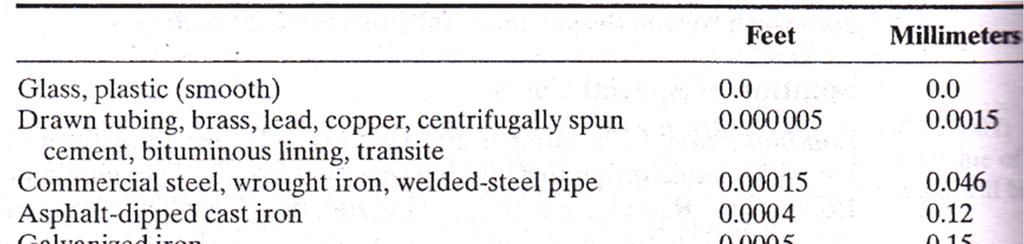
16 Friction Factor for Laminar and Turbulent Flows in Circular Pipes The friction factor can be determined by its Reynolds number (Re) and the Relative roughness (e/d) of the Pipe.( where: e absolute roughness and D diameter of pipe) 6
17 7
18 Problem Types Type : Determine f and hf, Type : Determine Q Type 3: Determine D 8
19 Problem Find friction factor for the following pipe e0.00 ft Dft Kinematic iscosity, ν4.x0-6 ft /s elocity of flow, 0.4ft/s Solution: e/d0.00/0.00 RD/ν x0.4/(4.x0-6 )0000 From Moody s Diagram; f0.034 f f / log e D Re f 9
20 Problem-Type Pipe dia 3 inch & L00m Re50,000 ʋ.059x0-5 ft /s (a): Laminar flow: f64/re64/50, Re D ν (3/) ft / s fl 0.008(00)(. ) H Lf gd (3.)(3/) ft 0
21 Problem-Type Pipe dia 3 inch & L00m Re50,000 ʋ.059x0-5 ft /s (b): Turbulent flow in smooth pipe: i.e.: e0 f f / log e D Re f log f fl 0.009(00)(. ) H Lf ft gd (3.)(3/)
22 Problem-Type Pipe dia 3 inch & L00m Re50,000 ʋ.059x0-5 ft /s (c): Turbulent flow in rough pipe: i.e.: e/d0.05 f f / log e D Re f log f fl 0.070(00)(. ) H Lf. 0 ft gd (3.)(3/)
23 Problem-Type h L? L 000 m; D 0.5m; e m 3 6 Q 0.05m / s; ν m / s R D / ν 3 6 ( ) /( ) e / D / From Moody's Diagram f fl h L 5. 39m gd 5 Q Q / A.039m / s
24 Problem-Type h L fl / gd 4
25 Problem-Type For laminar flow For non-laminar flow f 64 e / D.5 log f 3.7 Re f R e Colebrook eq. 5
26 Problem-Type 3 6
27 Problem h f Lf e / D log 3.7 fl gd.5 Re f 7
28 Problem 8
29 Problem 9
30 MINOR LOSSES Each type of loss can be quantified using a loss coefficient (K). Losses are proportional to velocity of flow and geometry of device. H m K g Where, H m is minor loss and K is minor loss coefficient. The value of K is typically provided for various types/devices NOTE: If L > 000D minor losses become significantly less than that of major losses and hence can be neglected. 30
31 Minor Losses These can be categorized as. Head loss due to contraction in pipe. Sudden Contraction. Gradual Contraction. Entrance loss 3. Head loss due to enlargement of pipe 3. Sudden Enlargement 3. Gradual Enlargement 4. Exit loss 5. Head loss due to pipe fittings 6. Head loss due to bends and elbows 3
32 Minor Losses Head loss due to contraction of pipe (Sudden contraction) A sudden contraction (Figure) in pipe usually causes a marked drop in pressure in the pipe because of both the increase in velocity and the loss of energy of turbulence. Head loss due to sudden contraction is H m K c g Where, k c is sudden contraction coefficient and it value depends up ratio of D/D and velocity ( ) in smaller pipe 3
33 Minor Losses Head loss due to enlargement of pipe (Gradual Contraction) Head loss from pipe contraction may be greatly reduced by introducing a gradual pipe transition known as a confusor as shown Figure. Head loss due to gradual contraction is H m K c ' g Where, k c is gradual contraction coefficient and it value depends up ratio of D /D and velocity ( ) in smaller pipe 33
34 Minor Losses Entrance loss The general equation for an entrance head loss is also expressed in terms of velocity head of the pipe: H m Ke g The approximate values for the entrance loss coefficient (Ke) for different entrance conditions are given below 34
35 Minor Losses head loss due to enlargement of pipe (Sudden Enlargement) The behavior of the energy grade line and the hydraulic grade line in the vicinity of a sudden pipe expansion is shown in Figure The magnitude of the head loss may be expressed as ( ) H m g 35
36 Minor Losses head loss due to enlargement of pipe (Gradual Enlargement) The head loss resulting from pipe expansions may be greatly reduced by introducing a gradual pipe transition known as a diffusor The magnitude of the head loss may be expressed as H m K e ( ) g The values of Ke vary with the diffuser angle (α). 36
37 Minor Losses Exit Loss A submerged pipe discharging into a large reservoir (Figure ) is a special case of head loss from expansion. 37 Exit (discharge) head loss is expressed as H m K d ( ) g where the exit (discharge) loss coefficient K d.0.
38 Minor Losses Head loss due to fittings valves Fittings are installed in pipelines to control flow. As with other losses in pipes, the head loss through fittings may also be expressed in terms of velocity head in the pipe: H m K f g 38
39 Minor Losses Head loss due to bends The head loss produced at a bend was found to be dependent of the ratio the radius of curvature of the bend (R) to the diameter of the pipe (D). The loss of head due to a bend may be expressed in terms of the velocity head as H m K b g For smooth pipe bend of 90 0, the values of Kb for various values of R/D are listed in following table. 39
40 Minor Losses 40
41 4 Numerical Problems
42 4 Numerical Problems
43 Thank you Questions. Feel free to contact: 43
44 Fluid Mechanics Fluid Dynamics: (ii) Hydrodynamics: Different forms of energy in a flowing liquid, head, Bernoulli's equation and its application, Energy line and Hydraulic Gradient Line, and Energy Equation Dr. Mohsin Siddique Assistant Professor
45 Forms of Energy (). Kinetic Energy: Energy due to motion of body. A body of mass, m, when moving with velocity,, posses kinetic energy, KE m (). Potential Energy: Energy due to elevation of body above an arbitrary datum PE mgz (3). Pressure Energy: Energy due to pressure above datum, most usually its pressure above atmospheric PrE h!!! m and are mass and velocity of body Z is elevation of body from arbitrary datum m is the mass of body
46 Forms of Energy (4). Internal Energy: It is the energy that is associated with the molecular, or internal state of matter; it may be stored in many forms, including thermal, nuclear, chemical and electrostatic. 3
47 HEAD Head: Energy per unit weight is called head Kinetic head: Kinetic energy per unit weight KE Kinetic head m / mg QWeight mg Weight g Potential head: Potential energy per unit weigh PE Potential head / Weight ( mgz ) mg Z Pressure head: Pressure energy per unit weight Pressure head PrE Weight P 4
48 TOTAL HEAD TOTAL HEAD Kinetic Head Potential Head Pressure Head g Z P Total Head H Z P g 5
49 Bernoulli s Equation It states that the sum of kinetic, potential and pressure heads of a fluid particle is constant along a streamline during steady flow when compressibility and frictional effects are negligible. i.e., For an ideal fluid, Total head of fluid particle remains constant during a steady-incompressible flow. Or total head along a streamline is constant during steady flow when compressibility and frictional effects are negligible. Total Head Z P g constt Z H P g H Z P g Pipe 6
50 Derivation of Bernoulli s Equation Consider motion of flow fluid particle in steady flow field as shown in fig. Applying Newton s nd Law in s- direction on a particle moving along a streamline give Assumption: Fluid is ideal and incompressible Flow is steady Flow is along streamline elocity is uniform across the section and is equal to mean velocity Only gravity and pressure forces are acting F s ma s Eq() Where F is resultant force in s- direction, m is the mass and a s is the acceleration along s-direction. d dsd dsd a s dt dsdt dtds d ds Eq() 7 Fig. Forces acting on particle along streamline
51 Derivation of Bernoulli s Equation F s PdA ( P dp) da W sinθ Substituting values from Eq() and Eq(3) to Eq() ( P dp) PdA da W sinθ dz dpda ρ gdads ρdads ds m d ds Eq(3) d ds sinθ dz ds Cancelling da and simplifying dp ρ gdz ρd 8 Note that d d dp ρ gdz ρ d Eq(4) Eq(5) Fig. Forces acting on particle along streamline Wweight of fluid W mg ( ρdads)g Wsin( θ) component acting along s-direction da Area of flow dslength between sections along pipe
52 Derivation of Bernoulli s Equation Dividing eq (5) by ρ dp ρ Integrating gdz d dp gdz ρ d Assuming incompressible and steady flow P gz ρ Dividing each equation by g contt 0 contt Eq (6) Eq (7) Eq (8) Hence Eq (9) for steadincompressible fluid assuming no frictional losses can be written as Z P Z g ( Total Head) ( Total Head) P g Above Eq(0) is general form of Bernoulli s Equation Eq (0) 9 P ρg z g contt Eq (9)
53 Energy Line and Hydraulic Grade line Static Pressure : P Dynamic pressure : P Hydrostatic Pressure: ρgz z g H Pressure head Elevation head elocity head P ρgz ρ contt ρ / Total Head Multiplying with unit weight,, Stagnation Pressure: Static pressure dynamic Pressure P ρ P stag 0
54 Energy Line and Hydraulic Grade line Measurement of Heads Piezometer: It measures pressure head ( P / ). Pitot tube: It measures sum of pressure and velocity heads i.e., P g What about measurement of elevation head!!
55 Energy Line and Hydraulic Grade line Energy line: It is line joining the total heads along a pipe line. HGL: It is line joining pressure head along a pipe line.


56 Energy Line and Hydraulic Grade line 3
57 Energy Equation for steady flow of any fluid Let s consider the energy of system (Es) and energy of control volume(ecv) defined within a stream tube as shown in figure. Therefore, E s E C E out C E in C Eq() Because the flow is steady, conditions within the control volume does not change so E C Hence E 0 s E out C E in C Eq() Figure: Forces/energies in fluid flowing in streamt ube 4
58 Energy Equation for steady flow of any fluid Now, let s apply the first law of thermodynamics to the fluid system which states For steady flow, the external work done on any system plus the thermal energy transferred into or out of the system is equal to the change of energy of system External work done heat transferred change of energy ( flowwork shaftwork ) heat transferred Es out in ( flowwork shaftwork ) heat transferred E E C C Eq(3) Eq(4) Flow work: When the pressure forces acting on the boundaries move, in present case when p A and p A at the end sections move through s and s, external work is done. It is referred to as flow work. 5 Flow work p A s p A s p p Flow work g m p A s Q ρ A s p A s ρ A s m Eq(5) Steady flow
59 Energy Equation for steady flow of any fluid Shaft work: Work done by machine, if any, between section and Shaft work Shaft work weight time energy weight time A ( A s ) h m ( g m) h m Where, h m is the energy added to the flow by the machine per unit weight of flowing fluid. Note: if the machine is pump, which adds energy to the fluid, h m is positive and if the machine is turbine, which remove energy from fluid, h m is -ve HeatTransferred: The heat transferred from an external source into the fluid system over time interval t is Heat transferred A Heat transferred ds dt Q ds dt h ( A s ) Q H ( g m) Q H H t m t Eq(6) Eq(7) 6 Where, Q H is the amount of energy put into the flow by the external heat source per unit weight of flowing fluid. If the heat flow is out of the fluid, the value Q H is ve and vice versa
60 Energy Equation for steady flow of any fluid 7 Change in Energy: For steady flow during time interval t, the weight of fluid entering the control volume at section and leaving at section are both equal to g m. Thus the energy (PotentialKineticInternal) carried by g m is; ( ) ( ) I g z m g E I g z A ds t I g z dt ds A E I g z m g E I g z A ds t I g z dt ds A E out C out C in C in C α α α α α α α is kinetic energy correction factor and ~ Eq(8) Eq(9)
61 Energy Equation for steady flow of any fluid 8 Substituting all values from Eqs. (5),(6), (7), (8), & (9) in Eq(4) ( ) in C out E C E shaftwork lowwork ferred heat trans f ( ) ( ) I g z m g I g z m g m Q g m h g p p m g H m α α I g z I g z Q h p p H m α α I g z p Q h I g z p H m α α This is general form of energy equation, which applies to liquids, gases, vapors and to ideal fluids as well as real fluids with friction, both incompressible and compressible. The only restriction is that its for steady flow. Eq(0)
62 Energy Equation for steady flow of incompressible fluid 9 For incompressible fluids Substituting in Eq(0), we get ( ) I I g z p Q h g z p H m ( ) H m Q I I g z p h g z p m h L g z p h g z p Eq() ( ) H L Q I I h Q Where h L (I -I )-Q H head loss. It equal to is gain in internal energy minus any heat added by external source. H m is head removed/added by machines. It can also be referred to head loss due to pipe fitting, contraction, expansion and bends etc in pipes.
63 Energy Equation for steady flow of incompressible fluid 0 In the absence of machine, pipe fitting etc, Eq() can be written as When the head loss is caused only by wall or pipe friction, h L becomes h f, where h f is head loss due to friction h L g z p g z p Eq()
64 Power Rate of work done is termed as power PowerEnergy/time Power(Energy/weight)(weight/time) If H is total headtotal energy/weight and Q is the weight flow rate then above equation can be written as In BG: In SI: Power(H)(Q)QH Power in (horsepower)(h)(q)/550 Power in (Kilowatts)(H)(Q)/000 horsepower550ft.lb/s
65 Reading Assignment Kinetic energy correction factor Limitation of Bernoulli s Equation Application of hydraulic grade line and energy line
66 NUMERICALS 5.. 3
67 5..3 4
68 5.3. 5
69
70
71
72 Momentum and Forces in Fluid Flow We have all seen moving fluids exerting forces. The lift force on an aircraft is exerted by the air moving over the wing. A jet of water from a hose exerts a force on whatever it hits. In fluid mechanics the analysis of motion is performed in the same way as in solid mechanics - by use of Newton s laws of motion. i.e., F ma which is used in the analysis of solid mechanics to relate applied force to acceleration. In fluid mechanics it is not clear what mass of moving fluid we should use so we use a different form of the equation. 9 F ma d ( m) dt s
73 Momentum and Forces in Fluid Flow Newton s nd Law can be written: The Rate of change of momentum of a body is equal to the resultant force acting on the body, and takes place in the direction of the force. F d ( m) dt s F m Sum of all external forces on a body of fluid or system s Momentum of fluid body in direction s The symbols F and represent vectors and so the change in momentum must be in the same direction as force. F dt d ( m) s 30 It is also termed as impulse momentum principle
74 Impact of a Jet on a Plane 3
75 Impact of a Jet on a Plane 3
76 Thank you Questions. Feel free to contact: 33
Lesson 6 Review of fundamentals: Fluid flow
 Lesson 6 Review of fundamentals: Fluid flow The specific objective of this lesson is to conduct a brief review of the fundamentals of fluid flow and present: A general equation for conservation of mass
FE Fluids Review March 23, 2012 Steve Burian (Civil & Environmental Engineering)
") Topic: Fluid Properties 1. If 6 m 3 of oil weighs 47 kn, calculate its specific weight, density, and specific gravity. 2. 10.0 L of an incompressible liquid exert a force of 20 N at the earth s surface.
Topic: Fluid Properties 1. If 6 m 3 of oil weighs 47 kn, calculate its specific weight, density, and specific gravity. 2. 10.0 L of an incompressible liquid exert a force of 20 N at the earth s surface.
1-Reynold s Experiment
 Lect.No.8 2 nd Semester Flow Dynamics in Closed Conduit (Pipe Flow) 1 of 21 The flow in closed conduit ( flow in pipe ) is differ from this occur in open channel where the flow in pipe is at a pressure
Review of pipe flow: Friction & Minor Losses
 ENVE 204 Lecture -1 Review of pipe flow: Friction & Minor Losses Assist. Prof. Neslihan SEMERCİ Marmara University Department of Environmental Engineering Important Definitions Pressure Pipe Flow: Refers
vector H. If O is the point about which moments are desired, the angular moment about O is given:
 The angular momentum A control volume analysis can be applied to the angular momentum, by letting B equal to angularmomentum vector H. If O is the point about which moments are desired, the angular moment
Hydraulics for Urban Storm Drainage
 Urban Hydraulics Hydraulics for Urban Storm Drainage Learning objectives: understanding of basic concepts of fluid flow and how to analyze conduit flows, free surface flows. to analyze, hydrostatic pressure
Chapter Four fluid flow mass, energy, Bernoulli and momentum
 4-1Conservation of Mass Principle Consider a control volume of arbitrary shape, as shown in Fig (4-1). Figure (4-1): the differential control volume and differential control volume (Total mass entering
Chapter 4 DYNAMICS OF FLUID FLOW
 Faculty Of Engineering at Shobra nd Year Civil - 016 Chapter 4 DYNAMICS OF FLUID FLOW 4-1 Types of Energy 4- Euler s Equation 4-3 Bernoulli s Equation 4-4 Total Energy Line (TEL) and Hydraulic Grade Line
Pipe Flow. Lecture 17
 Pipe Flow Lecture 7 Pipe Flow and the Energy Equation For pipe flow, the Bernoulli equation alone is not sufficient. Friction loss along the pipe, and momentum loss through diameter changes and corners
Basic Fluid Mechanics
 Basic Fluid Mechanics Chapter 5: Application of Bernoulli Equation 4/16/2018 C5: Application of Bernoulli Equation 1 5.1 Introduction In this chapter we will show that the equation of motion of a particle
Chapter (3) Water Flow in Pipes
 Water Flow in Pipes") Chapter (3) Water Flow in Pipes Water Flow in Pipes Bernoulli Equation Recall fluid mechanics course, the Bernoulli equation is: P 1 ρg + v 1 g + z 1 = P ρg + v g + z h P + h T + h L Here, we want to study
Chapter (3) Water Flow in Pipes Water Flow in Pipes Bernoulli Equation Recall fluid mechanics course, the Bernoulli equation is: P 1 ρg + v 1 g + z 1 = P ρg + v g + z h P + h T + h L Here, we want to study
EXPERIMENT No.1 FLOW MEASUREMENT BY ORIFICEMETER
 EXPERIMENT No.1 FLOW MEASUREMENT BY ORIFICEMETER 1.1 AIM: To determine the co-efficient of discharge of the orifice meter 1.2 EQUIPMENTS REQUIRED: Orifice meter test rig, Stopwatch 1.3 PREPARATION 1.3.1
V/ t = 0 p/ t = 0 ρ/ t = 0. V/ s = 0 p/ s = 0 ρ/ s = 0
 UNIT III FLOW THROUGH PIPES 1. List the types of fluid flow. Steady and unsteady flow Uniform and non-uniform flow Laminar and Turbulent flow Compressible and incompressible flow Rotational and ir-rotational
Chapter (3) Water Flow in Pipes
 Water Flow in Pipes") Chapter (3) Water Flow in Pipes Water Flow in Pipes Bernoulli Equation Recall fluid mechanics course, the Bernoulli equation is: P 1 ρg + v 1 g + z 1 = P ρg + v g + z h P + h T + h L Here, we want to study
Chapter (3) Water Flow in Pipes Water Flow in Pipes Bernoulli Equation Recall fluid mechanics course, the Bernoulli equation is: P 1 ρg + v 1 g + z 1 = P ρg + v g + z h P + h T + h L Here, we want to study
Objectives. Conservation of mass principle: Mass Equation The Bernoulli equation Conservation of energy principle: Energy equation
 Objectives Conservation of mass principle: Mass Equation The Bernoulli equation Conservation of energy principle: Energy equation Conservation of Mass Conservation of Mass Mass, like energy, is a conserved
REE 307 Fluid Mechanics II. Lecture 1. Sep 27, Dr./ Ahmed Mohamed Nagib Elmekawy. Zewail City for Science and Technology
 REE 307 Fluid Mechanics II Lecture 1 Sep 27, 2017 Dr./ Ahmed Mohamed Nagib Elmekawy Zewail City for Science and Technology Course Materials drahmednagib.com 2 COURSE OUTLINE Fundamental of Flow in pipes
Reynolds, an engineering professor in early 1880 demonstrated two different types of flow through an experiment:
 7 STEADY FLOW IN PIPES 7.1 Reynolds Number Reynolds, an engineering professor in early 1880 demonstrated two different types of flow through an experiment: Laminar flow Turbulent flow Reynolds apparatus
Chapter 8: Flow in Pipes
 Objectives 1. Have a deeper understanding of laminar and turbulent flow in pipes and the analysis of fully developed flow 2. Calculate the major and minor losses associated with pipe flow in piping networks
Chapter 3 Water Flow in Pipes
 The Islamic University o Gaza Faculty o Engineering Civil Engineering Department Hydraulics - ECI 33 Chapter 3 Water Flow in Pipes 3. Description o A Pipe Flow Water pipes in our homes and the distribution
Basic Fluid Mechanics
 Basic Fluid Mechanics Chapter 6A: Internal Incompressible Viscous Flow 4/16/2018 C6A: Internal Incompressible Viscous Flow 1 6.1 Introduction For the present chapter we will limit our study to incompressible
Detailed Outline, M E 320 Fluid Flow, Spring Semester 2015
 Detailed Outline, M E 320 Fluid Flow, Spring Semester 2015 I. Introduction (Chapters 1 and 2) A. What is Fluid Mechanics? 1. What is a fluid? 2. What is mechanics? B. Classification of Fluid Flows 1. Viscous
INSTITUTE OF AERONAUTICAL ENGINEERING Dundigal, Hyderabad AERONAUTICAL ENGINEERING QUESTION BANK : AERONAUTICAL ENGINEERING.
 Course Name Course Code Class Branch INSTITUTE OF AERONAUTICAL ENGINEERING Dundigal, Hyderabad - 00 0 AERONAUTICAL ENGINEERING : Mechanics of Fluids : A00 : II-I- B. Tech Year : 0 0 Course Coordinator
FE Exam Fluids Review October 23, Important Concepts
 FE Exam Fluids Review October 3, 013 mportant Concepts Density, specific volume, specific weight, specific gravity (Water 1000 kg/m^3, Air 1. kg/m^3) Meaning & Symbols? Stress, Pressure, Viscosity; Meaning
2.The lines that are tangent to the velocity vectors throughout the flow field are called steady flow lines. True or False A. True B.
 CHAPTER 03 1. Write Newton's second law of motion. YOUR ANSWER: F = ma 2.The lines that are tangent to the velocity vectors throughout the flow field are called steady flow lines. True or False 3.Streamwise
Hydraulics and hydrology
 Hydraulics and hydrology - project exercises - Class 4 and 5 Pipe flow Discharge (Q) (called also as the volume flow rate) is the volume of fluid that passes through an area per unit time. The discharge
Chapter 10 Flow in Conduits
 Chapter 10 Flow in Conduits 10.1 Classifying Flow Laminar Flow and Turbulent Flow Laminar flow Unpredictable Turbulent flow Near entrance: undeveloped developing flow In developing flow, the wall shear
Fluid Mechanics II 3 credit hour. Fluid flow through pipes-minor losses
 COURSE NUMBER: ME 323 Fluid Mechanics II 3 credit hour Fluid flow through pipes-minor losses Course teacher Dr. M. Mahbubur Razzaque Professor Department of Mechanical Engineering BUET 1 Losses in Noncircular
BERNOULLI EQUATION. The motion of a fluid is usually extremely complex.
 BERNOULLI EQUATION The motion of a fluid is usually extremely complex. The study of a fluid at rest, or in relative equilibrium, was simplified by the absence of shear stress, but when a fluid flows over
Steven Burian Civil & Environmental Engineering September 25, 2013
 Fundamentals of Engineering (FE) Exam Mechanics Steven Burian Civil & Environmental Engineering September 25, 2013 s and FE Morning ( Mechanics) A. Flow measurement 7% of FE Morning B. properties Session
Hydraulics. B.E. (Civil), Year/Part: II/II. Tutorial solutions: Pipe flow. Tutorial 1
, Year/Part: II/II. Tutorial solutions: Pipe flow. Tutorial 1") Hydraulics B.E. (Civil), Year/Part: II/II Tutorial solutions: Pipe flow Tutorial 1 -by Dr. K.N. Dulal Laminar flow 1. A pipe 200mm in diameter and 20km long conveys oil of density 900 kg/m 3 and viscosity
Hydraulics B.E. (Civil), Year/Part: II/II Tutorial solutions: Pipe flow Tutorial 1 -by Dr. K.N. Dulal Laminar flow 1. A pipe 200mm in diameter and 20km long conveys oil of density 900 kg/m 3 and viscosity
Viscous Flow in Ducts
 Dr. M. Siavashi Iran University of Science and Technology Spring 2014 Objectives 1. Have a deeper understanding of laminar and turbulent flow in pipes and the analysis of fully developed flow 2. Calculate
FACULTY OF CHEMICAL & ENERGY ENGINEERING FLUID MECHANICS LABORATORY TITLE OF EXPERIMENT: MINOR LOSSES IN PIPE (E4)
") FACULTY OF CHEMICAL & ENERGY ENGINEERING FLUID MECHANICS LABORATORY TITLE OF EXPERIMENT: MINOR LOSSES IN PIPE (E4) 1 1.0 Objectives The objective of this experiment is to calculate loss coefficient (K
FACULTY OF CHEMICAL & ENERGY ENGINEERING FLUID MECHANICS LABORATORY TITLE OF EXPERIMENT: MINOR LOSSES IN PIPE (E4) 1 1.0 Objectives The objective of this experiment is to calculate loss coefficient (K
Chapter 6. Losses due to Fluid Friction
 Chapter 6 Losses due to Fluid Friction 1 Objectives ä To measure the pressure drop in the straight section of smooth, rough, and packed pipes as a function of flow rate. ä To correlate this in terms of
Piping Systems and Flow Analysis (Chapter 3)
") Piping Systems and Flow Analysis (Chapter 3) 2 Learning Outcomes (Chapter 3) Losses in Piping Systems Major losses Minor losses Pipe Networks Pipes in series Pipes in parallel Manifolds and Distribution
Piping Systems and Flow Analysis (Chapter 3) 2 Learning Outcomes (Chapter 3) Losses in Piping Systems Major losses Minor losses Pipe Networks Pipes in series Pipes in parallel Manifolds and Distribution
Pressure Head: Pressure head is the height of a column of water that would exert a unit pressure equal to the pressure of the water.
 Design Manual Chapter - Stormwater D - Storm Sewer Design D- Storm Sewer Sizing A. Introduction The purpose of this section is to outline the basic hydraulic principles in order to determine the storm
2 Internal Fluid Flow
 Internal Fluid Flow.1 Definitions Fluid Dynamics The study of fluids in motion. Static Pressure The pressure at a given point exerted by the static head of the fluid present directly above that point.
s and FE X. A. Flow measurement B. properties C. statics D. impulse, and momentum equations E. Pipe and other internal flow 7% of FE Morning Session I
 Fundamentals of Engineering (FE) Exam General Section Steven Burian Civil & Environmental Engineering October 26, 2010 s and FE X. A. Flow measurement B. properties C. statics D. impulse, and momentum
EGN 3353C Fluid Mechanics
 Lecture 8 Bernoulli s Equation: Limitations and Applications Last time, we derived the steady form of Bernoulli s Equation along a streamline p + ρv + ρgz = P t static hydrostatic total pressure q = dynamic
Where does Bernoulli's Equation come from?
 Where does Bernoulli's Equation come from? Introduction By now, you have seen the following equation many times, using it to solve simple fluid problems. P ρ + v + gz = constant (along a streamline) This
Chapter 7 The Energy Equation
 Chapter 7 The Energy Equation 7.1 Energy, Work, and Power When matter has energy, the matter can be used to do work. A fluid can have several forms of energy. For example a fluid jet has kinetic energy,
Rate of Flow Quantity of fluid passing through any section (area) per unit time
 per unit time") Kinematics of Fluid Flow Kinematics is the science which deals with study of motion of liquids without considering the forces causing the motion. Rate of Flow Quantity of fluid passing through any section
Kinematics of Fluid Flow Kinematics is the science which deals with study of motion of liquids without considering the forces causing the motion. Rate of Flow Quantity of fluid passing through any section
CEE 3310 Control Volume Analysis, Oct. 10, = dt. sys
 CEE 3310 Control Volume Analysis, Oct. 10, 2018 77 3.16 Review First Law of Thermodynamics ( ) de = dt Q Ẇ sys Sign convention: Work done by the surroundings on the system < 0, example, a pump! Work done
STEADY FLOW THROUGH PIPES DARCY WEISBACH EQUATION FOR FLOW IN PIPES. HAZEN WILLIAM S FORMULA, LOSSES IN PIPELINES, HYDRAULIC GRADE LINES AND ENERGY
 STEADY FLOW THROUGH PIPES DARCY WEISBACH EQUATION FOR FLOW IN PIPES. HAZEN WILLIAM S FORMULA, LOSSES IN PIPELINES, HYDRAULIC GRADE LINES AND ENERGY LINES 1 SIGNIFICANCE OF CONDUITS In considering the convenience
Mechanical Engineering Programme of Study
 Mechanical Engineering Programme of Study Fluid Mechanics Instructor: Marios M. Fyrillas Email: eng.fm@fit.ac.cy SOLVED EXAMPLES ON VISCOUS FLOW 1. Consider steady, laminar flow between two fixed parallel
Angular momentum equation
 Angular momentum equation For angular momentum equation, B =H O the angular momentum vector about point O which moments are desired. Where β is The Reynolds transport equation can be written as follows:
Applied Fluid Mechanics
 Applied Fluid Mechanics 1. The Nature of Fluid and the Study of Fluid Mechanics 2. Viscosity of Fluid 3. Pressure Measurement 4. Forces Due to Static Fluid 5. Buoyancy and Stability 6. Flow of Fluid and
Fluid Mechanics. du dy
 FLUID MECHANICS Technical English - I 1 th week Fluid Mechanics FLUID STATICS FLUID DYNAMICS Fluid Statics or Hydrostatics is the study of fluids at rest. The main equation required for this is Newton's
Dimensions represent classes of units we use to describe a physical quantity. Most fluid problems involve four primary dimensions
 BEE 5330 Fluids FE Review, Feb 24, 2010 1 A fluid is a substance that can not support a shear stress. Liquids differ from gasses in that liquids that do not completely fill a container will form a free
CEE 3310 Control Volume Analysis, Oct. 7, D Steady State Head Form of the Energy Equation P. P 2g + z h f + h p h s.
 CEE 3310 Control Volume Analysis, Oct. 7, 2015 81 3.21 Review 1-D Steady State Head Form of the Energy Equation ( ) ( ) 2g + z = 2g + z h f + h p h s out where h f is the friction head loss (which combines
UNIFORM FLOW CRITICAL FLOW GRADUALLY VARIED FLOW
 UNIFORM FLOW CRITICAL FLOW GRADUALLY VARIED FLOW Derivation of uniform flow equation Dimensional analysis Computation of normal depth UNIFORM FLOW 1. Uniform flow is the flow condition obtained from a
Chapter 8: Flow in Pipes
 8-1 Introduction 8-2 Laminar and Turbulent Flows 8-3 The Entrance Region 8-4 Laminar Flow in Pipes 8-5 Turbulent Flow in Pipes 8-6 Fully Developed Pipe Flow 8-7 Minor Losses 8-8 Piping Networks and Pump
ENGINEERING FLUID MECHANICS. CHAPTER 1 Properties of Fluids
 CHAPTER 1 Properties of Fluids ENGINEERING FLUID MECHANICS 1.1 Introduction 1.2 Development of Fluid Mechanics 1.3 Units of Measurement (SI units) 1.4 Mass, Density, Specific Weight, Specific Volume, Specific
ME 305 Fluid Mechanics I. Part 8 Viscous Flow in Pipes and Ducts. Flow in Pipes and Ducts. Flow in Pipes and Ducts (cont d)
") ME 305 Fluid Mechanics I Flow in Pipes and Ducts Flow in closed conduits (circular pipes and non-circular ducts) are very common. Part 8 Viscous Flow in Pipes and Ducts These presentations are prepared
ME 305 Fluid Mechanics I Flow in Pipes and Ducts Flow in closed conduits (circular pipes and non-circular ducts) are very common. Part 8 Viscous Flow in Pipes and Ducts These presentations are prepared
CLASS SCHEDULE 2013 FALL
 CLASS SCHEDULE 2013 FALL Class # or Lab # 1 Date Aug 26 2 28 Important Concepts (Section # in Text Reading, Lecture note) Examples/Lab Activities Definition fluid; continuum hypothesis; fluid properties
Chapter 10: Flow Flow in in Conduits Conduits Dr Ali Jawarneh
 Chater 10: Flow in Conduits By Dr Ali Jawarneh Hashemite University 1 Outline In this chater we will: Analyse the shear stress distribution across a ie section. Discuss and analyse the case of laminar
B.E/B.Tech/M.E/M.Tech : Chemical Engineering Regulation: 2016 PG Specialisation : NA Sub. Code / Sub. Name : CH16304 FLUID MECHANICS Unit : I
 Department of Chemical Engineering B.E/B.Tech/M.E/M.Tech : Chemical Engineering Regulation: 2016 PG Specialisation : NA Sub. Code / Sub. Name : CH16304 FLUID MECHANICS Unit : I LP: CH 16304 Rev. No: 00
Experiment- To determine the coefficient of impact for vanes. Experiment To determine the coefficient of discharge of an orifice meter.
 SUBJECT: FLUID MECHANICS VIVA QUESTIONS (M.E 4 th SEM) Experiment- To determine the coefficient of impact for vanes. Q1. Explain impulse momentum principal. Ans1. Momentum equation is based on Newton s
Chapter (6) Energy Equation and Its Applications
 Energy Equation and Its Applications") Chapter (6) Energy Equation and Its Applications Bernoulli Equation Bernoulli equation is one of the most useful equations in fluid mechanics and hydraulics. And it s a statement of the principle of conservation
Chapter (6) Energy Equation and Its Applications Bernoulli Equation Bernoulli equation is one of the most useful equations in fluid mechanics and hydraulics. And it s a statement of the principle of conservation
Part A: 1 pts each, 10 pts total, no partial credit.
 Part A: 1 pts each, 10 pts total, no partial credit. 1) (Correct: 1 pt/ Wrong: -3 pts). The sum of static, dynamic, and hydrostatic pressures is constant when flow is steady, irrotational, incompressible,
Lecture 3 The energy equation
 Lecture 3 The energy equation Dr Tim Gough: t.gough@bradford.ac.uk General information Lab groups now assigned Timetable up to week 6 published Is there anyone not yet on the list? Week 3 Week 4 Week 5
PROPERTIES OF FLUIDS
 Unit - I Chapter - PROPERTIES OF FLUIDS Solutions of Examples for Practice Example.9 : Given data : u = y y, = 8 Poise = 0.8 Pa-s To find : Shear stress. Step - : Calculate the shear stress at various
Lesson 37 Transmission Of Air In Air Conditioning Ducts
 Lesson 37 Transmission Of Air In Air Conditioning Ducts Version 1 ME, IIT Kharagpur 1 The specific objectives of this chapter are to: 1. Describe an Air Handling Unit (AHU) and its functions (Section 37.1).
OE4625 Dredge Pumps and Slurry Transport. Vaclav Matousek October 13, 2004
 OE465 Vaclav Matousek October 13, 004 1 Dredge Vermelding Pumps onderdeel and Slurry organisatie Transport OE465 Vaclav Matousek October 13, 004 Dredge Vermelding Pumps onderdeel and Slurry organisatie
Mass of fluid leaving per unit time
 5 ENERGY EQUATION OF FLUID MOTION 5.1 Eulerian Approach & Control Volume In order to develop the equations that describe a flow, it is assumed that fluids are subject to certain fundamental laws of physics.
University of Engineering and Technology, Taxila. Department of Civil Engineering
 University of Engineering and Technology, Taxila Department of Civil Engineering Course Title: CE-201 Fluid Mechanics - I Pre-requisite(s): None Credit Hours: 2 + 1 Contact Hours: 2 + 3 Text Book(s): Reference
Aerodynamics. Basic Aerodynamics. Continuity equation (mass conserved) Some thermodynamics. Energy equation (energy conserved)
 Some thermodynamics. Energy equation (energy conserved)") Flow with no friction (inviscid) Aerodynamics Basic Aerodynamics Continuity equation (mass conserved) Flow with friction (viscous) Momentum equation (F = ma) 1. Euler s equation 2. Bernoulli s equation
Flow with no friction (inviscid) Aerodynamics Basic Aerodynamics Continuity equation (mass conserved) Flow with friction (viscous) Momentum equation (F = ma) 1. Euler s equation 2. Bernoulli s equation
FLUID MECHANICS PROF. DR. METİN GÜNER COMPILER
 FLUID MECHANICS PROF. DR. METİN GÜNER COMPILER ANKARA UNIVERSITY FACULTY OF AGRICULTURE DEPARTMENT OF AGRICULTURAL MACHINERY AND TECHNOLOGIES ENGINEERING 1 5. FLOW IN PIPES 5.1.3. Pressure and Shear Stress
ME3560 Tentative Schedule Fall 2018
 ME3560 Tentative Schedule Fall 2018 Week Number 1 Wednesday 8/29/2018 1 Date Lecture Topics Covered Introduction to course, syllabus and class policies. Math Review. Differentiation. Prior to Lecture Read
HEAT TRANSFER BY CONVECTION. Dr. Şaziye Balku 1
 HEAT TRANSFER BY CONVECTION Dr. Şaziye Balku 1 CONDUCTION Mechanism of heat transfer through a solid or fluid in the absence any fluid motion. CONVECTION Mechanism of heat transfer through a fluid in the
Convection. forced convection when the flow is caused by external means, such as by a fan, a pump, or atmospheric winds.
 Convection The convection heat transfer mode is comprised of two mechanisms. In addition to energy transfer due to random molecular motion (diffusion), energy is also transferred by the bulk, or macroscopic,
For example an empty bucket weighs 2.0kg. After 7 seconds of collecting water the bucket weighs 8.0kg, then:
 Hydraulic Coefficient & Flow Measurements ELEMENTARY HYDRAULICS National Certificate in Technology (Civil Engineering) Chapter 3 1. Mass flow rate If we want to measure the rate at which water is flowing
An overview of the Hydraulics of Water Distribution Networks
 An overview of the Hydraulics of Water Distribution Networks June 21, 2017 by, P.E. Senior Water Resources Specialist, Santa Clara Valley Water District Adjunct Faculty, San José State University 1 Outline
FLUID MECHANICS. Chapter 3 Elementary Fluid Dynamics - The Bernoulli Equation
 FLUID MECHANICS Chapter 3 Elementary Fluid Dynamics - The Bernoulli Equation CHAP 3. ELEMENTARY FLUID DYNAMICS - THE BERNOULLI EQUATION CONTENTS 3. Newton s Second Law 3. F = ma along a Streamline 3.3
ME3560 Tentative Schedule Spring 2019
 ME3560 Tentative Schedule Spring 2019 Week Number Date Lecture Topics Covered Prior to Lecture Read Section Assignment Prep Problems for Prep Probs. Must be Solved by 1 Monday 1/7/2019 1 Introduction to
CHAPTER 3 BASIC EQUATIONS IN FLUID MECHANICS NOOR ALIZA AHMAD
 CHAPTER 3 BASIC EQUATIONS IN FLUID MECHANICS 1 INTRODUCTION Flow often referred as an ideal fluid. We presume that such a fluid has no viscosity. However, this is an idealized situation that does not exist.
3.25 Pressure form of Bernoulli Equation
 CEE 3310 Control Volume Analysis, Oct 3, 2012 83 3.24 Review The Energy Equation Q Ẇshaft = d dt CV ) (û + v2 2 + gz ρ d + (û + v2 CS 2 + gz + ) ρ( v n) da ρ where Q is the heat energy transfer rate, Ẇ
COURSE NUMBER: ME 321 Fluid Mechanics I 3 credit hour. Basic Equations in fluid Dynamics
 COURSE NUMBER: ME 321 Fluid Mechanics I 3 credit hour Basic Equations in fluid Dynamics Course teacher Dr. M. Mahbubur Razzaque Professor Department of Mechanical Engineering BUET 1 Description of Fluid
Chapter 5: Mass, Bernoulli, and Energy Equations
 Chapter 5: Mass, Bernoulli, and Energy Equations Introduction This chapter deals with 3 equations commonly used in fluid mechanics The mass equation is an expression of the conservation of mass principle.
NPTEL Quiz Hydraulics
 Introduction NPTEL Quiz Hydraulics 1. An ideal fluid is a. One which obeys Newton s law of viscosity b. Frictionless and incompressible c. Very viscous d. Frictionless and compressible 2. The unit of kinematic
Fundamentals of Fluid Mechanics
 Sixth Edition Fundamentals of Fluid Mechanics International Student Version BRUCE R. MUNSON DONALD F. YOUNG Department of Aerospace Engineering and Engineering Mechanics THEODORE H. OKIISHI Department
Pressure and Flow Characteristics
 Pressure and Flow Characteristics Continuing Education from the American Society of Plumbing Engineers August 2015 ASPE.ORG/ReadLearnEarn CEU 226 READ, LEARN, EARN Note: In determining your answers to
Fluid Mechanics c) Orificemeter a) Viscous force, Turbulence force, Compressible force a) Turbulence force c) Integration d) The flow is rotational
 Orificemeter a) Viscous force, Turbulence force, Compressible force a) Turbulence force c) Integration d) The flow is rotational") Fluid Mechanics 1. Which is the cheapest device for measuring flow / discharge rate. a) Venturimeter b) Pitot tube c) Orificemeter d) None of the mentioned 2. Which forces are neglected to obtain Euler
Fluid Mechanics 1. Which is the cheapest device for measuring flow / discharge rate. a) Venturimeter b) Pitot tube c) Orificemeter d) None of the mentioned 2. Which forces are neglected to obtain Euler
ME 305 Fluid Mechanics I. Chapter 8 Viscous Flow in Pipes and Ducts
 ME 305 Fluid Mechanics I Chapter 8 Viscous Flow in Pipes and Ducts These presentations are prepared by Dr. Cüneyt Sert Department of Mechanical Engineering Middle East Technical University Ankara, Turkey
UNIT I FLUID PROPERTIES AND STATICS
 SIDDHARTH GROUP OF INSTITUTIONS :: PUTTUR Siddharth Nagar, Narayanavanam Road 517583 QUESTION BANK (DESCRIPTIVE) Subject with Code : Fluid Mechanics (16CE106) Year & Sem: II-B.Tech & I-Sem Course & Branch:
FLUID MECHANICS D203 SAE SOLUTIONS TUTORIAL 2 APPLICATIONS OF BERNOULLI SELF ASSESSMENT EXERCISE 1
 FLUID MECHANICS D203 SAE SOLUTIONS TUTORIAL 2 APPLICATIONS OF BERNOULLI SELF ASSESSMENT EXERCISE 1 1. A pipe 100 mm bore diameter carries oil of density 900 kg/m3 at a rate of 4 kg/s. The pipe reduces
ME 309 Fluid Mechanics Fall 2010 Exam 2 1A. 1B.
 Fall 010 Exam 1A. 1B. Fall 010 Exam 1C. Water is flowing through a 180º bend. The inner and outer radii of the bend are 0.75 and 1.5 m, respectively. The velocity profile is approximated as C/r where C
3.8 The First Law of Thermodynamics and the Energy Equation
 CEE 3310 Control Volume Analysis, Sep 30, 2011 65 Review Conservation of angular momentum 1-D form ( r F )ext = [ˆ ] ( r v)d + ( r v) out ṁ out ( r v) in ṁ in t CV 3.8 The First Law of Thermodynamics and
Basics of fluid flow. Types of flow. Fluid Ideal/Real Compressible/Incompressible
 Basics of fluid flow Types of flow Fluid Ideal/Real Compressible/Incompressible Flow Steady/Unsteady Uniform/Non-uniform Laminar/Turbulent Pressure/Gravity (free surface) 1 Basics of fluid flow (Chapter
The Bernoulli Equation
 The Bernoulli Equation The most used and the most abused equation in fluid mechanics. Newton s Second Law: F = ma In general, most real flows are 3-D, unsteady (x, y, z, t; r,θ, z, t; etc) Let consider
PIPE FLOWS: LECTURE /04/2017. Yesterday, for the example problem Δp = f(v, ρ, μ, L, D) We came up with the non dimensional relation
 We came up with the non dimensional relation") /04/07 ECTURE 4 PIPE FOWS: Yesterday, for the example problem Δp = f(v, ρ, μ,, ) We came up with the non dimensional relation f (, ) 3 V or, p f(, ) You can plot π versus π with π 3 as a parameter. Or,
/04/07 ECTURE 4 PIPE FOWS: Yesterday, for the example problem Δp = f(v, ρ, μ,, ) We came up with the non dimensional relation f (, ) 3 V or, p f(, ) You can plot π versus π with π 3 as a parameter. Or,
Experiment (4): Flow measurement
: Flow measurement") Experiment (4): Flow measurement Introduction: The flow measuring apparatus is used to familiarize the students with typical methods of flow measurement of an incompressible fluid and, at the same time
Experiment (4): Flow measurement Introduction: The flow measuring apparatus is used to familiarize the students with typical methods of flow measurement of an incompressible fluid and, at the same time
CIE4491 Lecture. Hydraulic design
 CIE4491 Lecture. Hydraulic design Marie-claire ten Veldhuis 19-9-013 Delft University of Technology Challenge the future Hydraulic design of urban stormwater systems Focus on sewer pipes Pressurized and
Chapter 5: Mass, Bernoulli, and
 and Energy Equations 5-1 Introduction 5-2 Conservation of Mass 5-3 Mechanical Energy 5-4 General Energy Equation 5-5 Energy Analysis of Steady Flows 5-6 The Bernoulli Equation 5-1 Introduction This chapter
Pressure in stationary and moving fluid Lab- Lab On- On Chip: Lecture 2
 Pressure in stationary and moving fluid Lab-On-Chip: Lecture Lecture plan what is pressure e and how it s distributed in static fluid water pressure in engineering problems buoyancy y and archimedes law;
Chapter 3 Bernoulli Equation
 1 Bernoulli Equation 3.1 Flow Patterns: Streamlines, Pathlines, Streaklines 1) A streamline, is a line that is everywhere tangent to the velocity vector at a given instant. Examples of streamlines around
Friction Factors and Drag Coefficients
 Levicky 1 Friction Factors and Drag Coefficients Several equations that we have seen have included terms to represent dissipation of energy due to the viscous nature of fluid flow. For example, in the
If a stream of uniform velocity flows into a blunt body, the stream lines take a pattern similar to this: Streamlines around a blunt body
 Venturimeter & Orificemeter ELEMENTARY HYDRAULICS National Certificate in Technology (Civil Engineering) Chapter 5 Applications of the Bernoulli Equation The Bernoulli equation can be applied to a great
5 ENERGY EQUATION OF FLUID MOTION
 5 ENERGY EQUATION OF FLUID MOTION 5.1 Introduction In order to develop the equations that describe a flow, it is assumed that fluids are subject to certain fundamental laws of physics. The pertinent laws
Convective Mass Transfer
 Convective Mass Transfer Definition of convective mass transfer: The transport of material between a boundary surface and a moving fluid or between two immiscible moving fluids separated by a mobile interface
Approximate physical properties of selected fluids All properties are given at pressure kn/m 2 and temperature 15 C.
 Appendix FLUID MECHANICS Approximate physical properties of selected fluids All properties are given at pressure 101. kn/m and temperature 15 C. Liquids Density (kg/m ) Dynamic viscosity (N s/m ) Surface