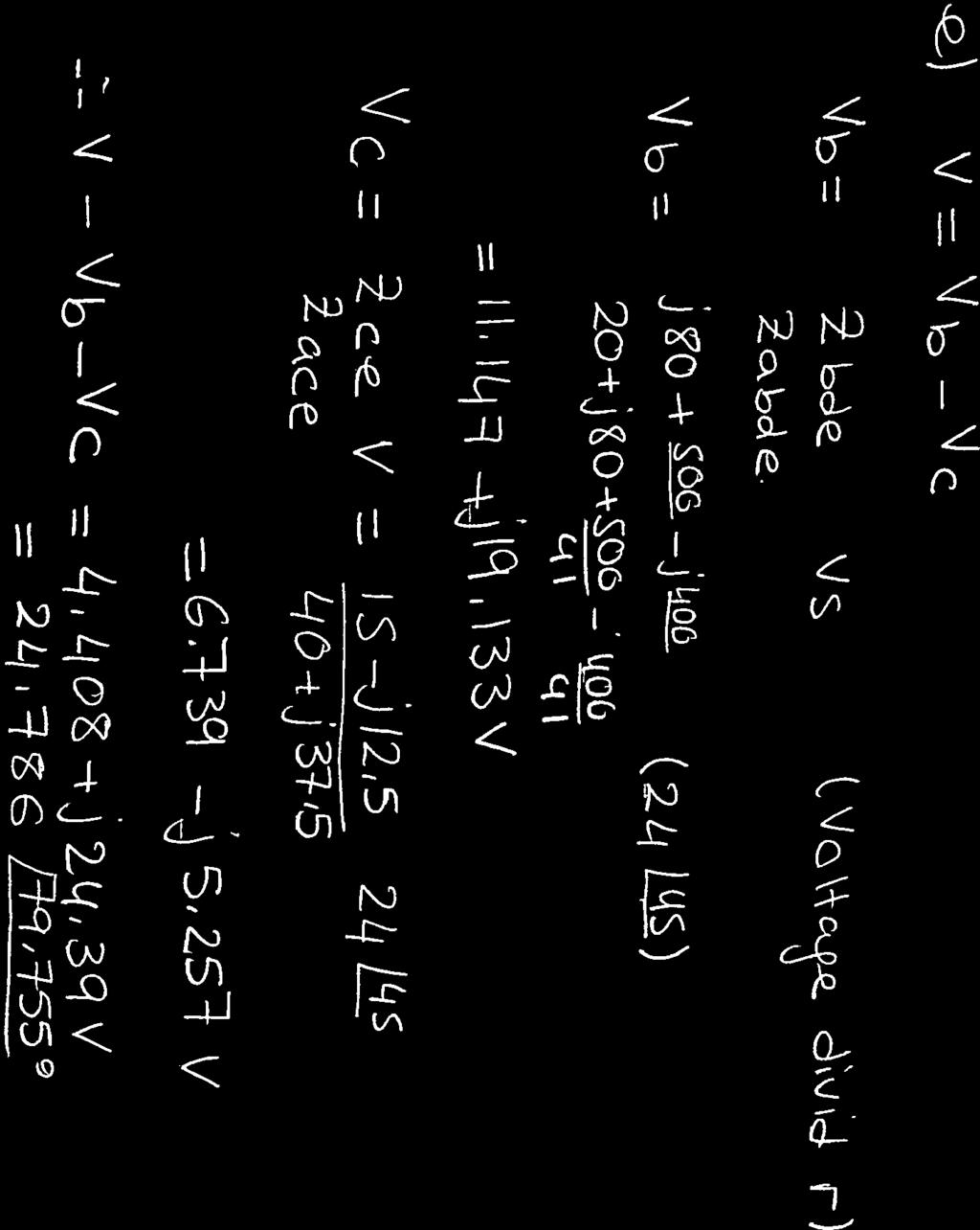
Read each question and its parts carefully before starting. Show all your work. Give units with your answers (where appropriate). 1 / 3 F.
|
|
|
- Poppy Reeves
- 5 years ago
- Views:
Transcription
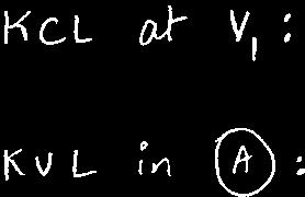
1 ECSE 10 NAME: Quiz 18 May 011 ID: Read each question and its parts carefully before starting. Show all your work. Give units with your answers (where appropriate). 1. Consider the circuit diagram below. [3pt] (a) Find the current phasor I. [3pt] 1 / 3 F 1 / 6 H i i c cos3t V sin3t A _ ¼ i c Solution: 1 / 3 F A 1 / 6 H i i c cos3t V sin3t A _ ¼ i c cos 3t = 0 sin 3t = 1 π [0.5pt] Applying KCL at node A: Z L = jlω = j I c Z C = 1 jcω = j 1 4 jlω 1 π 0 1 jcω = I 1 I c j 1 π j = I [1pt] I = 1 j = π [1pt] 4 I = cos 3t π 4 [1pt] [0.5pt] 1
2 ECSE 10 Quiz 18 May 011. Consider the circuit diagram below. [7pt] (a) Assume that the circuit in steady state, find v(t) [7pt] 4Ω 10μF Ω 4 Ω sin5000t V cos10000t A v 3 V 1mH - Solution: The voltage and current sources have different frequencies, so we use the principle of superposition. Considering the DC voltage source and set other sources to zero (open circuit the current source and short circuit the voltage source). v = 3 4 = v [1pt] 4 Considering the AC voltage source and set other sources to zero (open circuit the current source and short circuit the voltage source). Applying KCL: v 4 j5 v v ( j) 4 j0 = 0 [1pt] v = 10 j8 66 j45 = [1.5pt] Considering the AC current source and set other sources to zero (short circuit the voltage sources). Applying superposition: v 4 j10 v v (1 j0) = 0 [1pt] 4 j10 v = = [1.5pt] v =.6cos(5000t 0.077) 1.76cos(10000t) [1pt]
3 Question 1: [Points: 100] The operational amplifier is ideal. Using phasor method, find the steady-state expression for V ( t ) V t = cos10 tv. when ( ) 6 in out Solution: 1 jωc ( )( ) ( ) = j100k VO VO = j VO 0 VO = 0 j j40 jv V = 0 O O 1 jv = j40 V O O O j40 = = 0 j0 = 8.8R135 1 j 6 ( ) = 8.8cos( ) V t t V
4
5
6
7 ECSE 10 NAME: Quiz September 011 ID: Read each question and its parts carefully before starting. Show all your work. Give units with your answers (where appropriate). 1. Consider the circuit diagram below. The switch is opened at t = 0 after having been closed for a long time. [10pt] (a) Find the second-order differential equation governing v 1 (t) for t 0. [4pt] (b) Find the value of R which makes the circuit behave as an oscillator. [pt] (c) Determine v 1 for t 0.[4pt] t=0 4V 1 F v 1-1 H _ 5i R i 3 Ω Solution: t=0 1 4V i1 1 F v 1 - i 1 H _ 5i R i 3 Ω 1
8 ECSE 10 NAME: Quiz September 011 ID: Applying KCL at node 1: v 1 = di dt Ri The characteristic equation: i i 1 i = 0 i = v 1 5i 3 i 1 = dv 1 dt i = v 1 i = v 1 dv 1 dt d v 1 dt (R 1 )dv 1 dt (1 R )v 1 = 0 [4pt] λ (R 1 )λ (1 R ) = 0 For an oscillator α should be 0 and ω > 0: [1pt] R = 1 [1pt] R = λ = ±j v 1(t) = A cos t B sin t [pt] Initial Conditions: [1pt] v 1 v 1 (0 ) = v 1 (0 ) = 4V i (0 ) = i (0 ) = 8A (0 ) dv 1 dt (0 ) = i (0 ) Applying initial conditions: A = 4 B = v 1 (t) = 4 cos t 4 3 sin dv 1 dt (0 ) = 6 3 t [1pt]
9 SoLUTI()r/~ NAME: _-'- ID#: _ - ECSE 10: Electric Circuits Quiz # Wednesday September 3 rd, Write all of your solutions directly on the question sheet Use the back of the pages if you need more room The quiz is 30 minutes and consists of two problems The exam is out of 10 points. Good luck!
10 Ifit/gnp/{ # JI (g PCI y = 6J<g ~ V:=: 10 j's-:j.j: (7) 'RorlJ-'Jl 8y-" 5"0"4 V I = /0 /(;J. ~~. -= /0M = "',.,f.[ d.f [tj. 5"1 ('i i) J(OT~rE By 'fad ~ I! V = 105'5.)" 'foe =' 10/143./ 0 & 1T,"-== 3L6o~ = J S t-j R!>98 = - 8J6 [O '~l ~= gl-:ltr,s." -::: ] 3CfI -cfg 06J.. -vi t-y z =- 9 gc{/ - JO 1{ 63 ~ 8 QO j- ;l Cf 'i 0 => V, CY~ = g. 'I c»s (R.t - -v: Elts IL t I:>0 # e vj I Til C IlLCI.J J../rTO R.
11 -----=f--"'"\--4--.,----r -t r~ Ecl. ftvesrlpn #... 7' PO /N"T>.. ' y-----.j 4CfJ.$1:. fa u(t).. _ J~Jt. 1i.,- Vc.{ 0) 71(0-) =tvc (ot) = g v. G
12 IE 1RIAL. F(5(J.1-'1 of F"R. CE:!:> ~"L!:!.: tv! ft) = IJ ~jni 1- g ClZ i: c..tl/ li { de :: A usl.t. 9.s in t ; d~vr- ~~.- _ A.5 in-{;- g C OJ 1:. ~ Sv8511TIJrlH G] d1j.j. d?lf 7/jINTO TfJ 7'H~ t3.d-g dt:l dt".j AM]) ];5(\//tTIHev ' COEFFI~ ~,.,r~ I ;(.S-'l.IO\'/t- 1'f./()68 =0 1)(10'1}. ~'1/0 " g =- 1-,.10 t" ~ 1:: / 6;<10 -S- ; 8 = 4. Vc f;t) -= _'.6 )f./os's/n. t it c~s t [v1 / f C ItfH.fK- rz /<J~ TIt: s 1.. f I'!/" G s f ~ "SX1011 =0 6/'1 ~oot3 ; S,:= S.<... = -S-OOI &CtO (Ef(lJAL ~ P. ltl-) ~ C f? I -n CR-LL'I J>A-MP E A [ I]
13 ECSE 10, Summer 010 Quiz Total Points: 10 NAME: Write your solutions directly on the question sheet. need more room. SID: Use the backs of the pages if you Problem 1 (5 points) For the circuit shown in Fig. 1, V 1 = 7.81 of the input current source. 0.9 o V. Find the magnitude and angle Solution 1 j 1 5 I x? 10 V -j5 V 1 0 I x Figure 1: Problem 1 Summing the currents away from node 1 gives: V 1 V 1 j V 1 j5 V 1 0I x 5 = 0 (1) From the figure 1, I x is given by: Substituting I x and V 1 = 7.81 I x = V V 1 1 j 0.9 o = 68 j6 in eqn. 1 gives: () V = j16.80 Now summing the currents away from node yields: Substituting values of V 1 and V in eqn. 3 gives: I V 10 V V 1 1 j = 0 (3) I = o A 1
14 ECSE 10, Summer 010 Quiz Total Points: 10 Problem (5 points) The two loads shown in Fig. can be described as follows: L 1 absorbs an average power of 8kW at a leading power factor of 0.8. L absorbs 0kVA at a lagging power factor of 0.6. a)determine the power factor of two loads in parallel. b)determine the apparent power required to supply the loads. c)determine the magnitude of the current I s and the average power loss in the transmission line. d)given that the frequency of the source is 60Hz, compute the value of the capacitor that would correct the power factor to 1 if placed in parallel with the two loads j0.5 I s Vs 50 0 o V (rms) L1 I 1 L I Figure : Problem Solution a)the total complex power absorbed by the two loads is S = 50Is (4) = 50(I 1 I ) = 50I1 50I S = S 1 S S = P 1 jq 1 P jq (5) Now we know that P = S cos θ and Q = S sin θ, therefore eqn. 5 becomes Substituting values, S = P 1 j P 1 sin θ cos θ S cos θ j S sin θ Now using eqn. 4, S = 8000 j 8000(0.6) 0.8 I s = 0000(0.6) j0000(0.8) S = 0 j10 kva (6) 0000 j = 80 j40
15 ECSE 10, Summer 010 Quiz Total Points: 10 I s = 80 j40 = Therefore power factor of the combined loads: 6.57 o A pf = cos(θ v θ i ) = cos(0 6.57) = lagging b) The apparent power required to supply the loads: S = 0 j10 =.36 kva c)magnitude of the current: I s = 80 j40 = A Therefore, average power loss in the transmission line is: P line = I s R = (89.44) (0.05) = 400 W d)from eqn. 6, capacitor needs to supply 10 kvar to correct the pf to 1. i.e. Q = V rms X c Therefore, X c = = 6.5Ω C = 1 wx c = 1 π(60)( 6.5) = 44.4µF 3
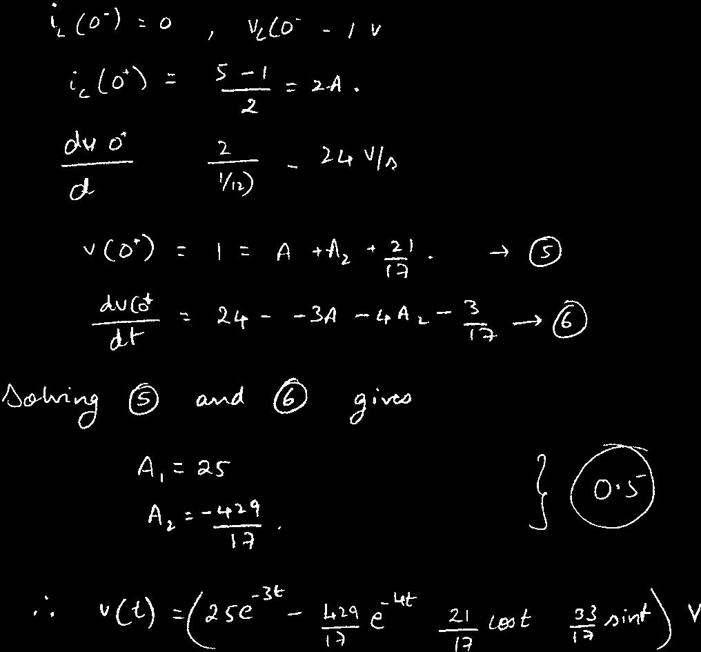
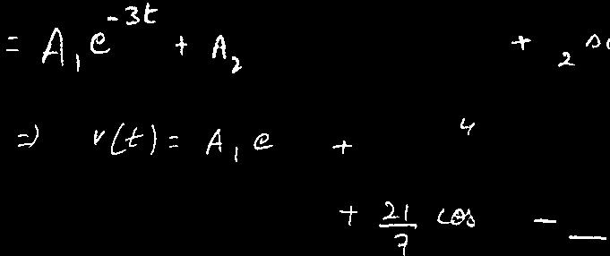
16 ECSE 10: Electric Circuits Quiz # (January 3, 009) Name McGill ID # Question 1: (5 min, Marks) a) Determine the frequency and the phase angle between the two voltages: v ( t) = 10sin(500t 70 ) V v ( t) = 6cos(500t 30 ) V 1 f w 500 = = = π π (1 Mark) v ( t) = 6cos(500t 30 ) V = 6cos(500t 60 ) V = 6cos(500t 10 ) V = 6cos(500t 300 ) V Phase angle between two voltages: 70 ( 60) = 130 (1 Mark) Question : (8 marks, 5 min.) Find v(t) and i(t) for t>0 in this circuit. Solution) i) At t v(0 v(0 i(0 = 0 ) = 1V At t = 0 ) = v(0 ) = i(0 i(0 ) = 1V ) = 0 ) = 0 (1 Mark)
17 ECSE 10: Electric Circuits Quiz # (January 3, 009) ii) Applying KCL at node a v(0 ) i(0 ) = ic (0 ) 1 0 = ic (0 ) ic (0 ) = 6A dv(0 ) 6 = = 1 V/s dt v( ) = i( ) = 4V, i( ) = 4 = A (1 Mark) iii) Applying KCL at node v 1 dv i = (1) dt Left mesh di 4i 1 v = 0 () dt from(1)() a dv v dt 1 dv dt 1 d v v = 0 dt or 6v 5 dv dt d v dt = 0 ( Marks) characteristic equation s v v n f 5s 6 = 0 ==> s =, 3 the natural response ( t) = v( t) = v Ae n t ( t) = v( ) = 4 v f Be 3t the forced response the complete response = 4 Ae t Be (1 Mark) (1 Mark) 3t
18 ECSE 10: Electric Circuits Quiz # (January 3, 009) determine v(0) = 1 ==> taking the A and A B = 8 (1) derivative B using the dv t 3t = Ae 3Be dt t = 0 ==> A 3B = 1 () initial values from(1)() A = 1 v( t) = 4 1e v i = = 6e 1 = 6e B = 4 t t dv dt t e 4e 4e 3t 3t 1e A, 3t V, t t > 0 t > 0 6e 3t (1 Mark) (1 Mark)
19
20
21
22
23
24
25
26
27
28
29


30
31 ECSE 10 NAME: Quiz # September 7, 01 ID: Read each question and its parts carefully before starting. Show all your work. Give units with your answers (where appropriate). 1. Determine the frequency(in Hertz) of and the phase angle between the two following current waveforms. [pt] i 1 (t) = 4 cos(377t 65 ) i (t) = 3 sin(377t 45 ) Solution: freq = 377 π = 60Hz [0.5pt] i 1 (t) = 4 cos(377t 65 ) = 4 cos(377t (65 180) ) = 4 cos(377t 115 ) i (t) = 3 sin(377t 45 ) = 3 cos(377t (45 90) ) = 3 cos(377t 45 ) [0.5pt] [0.5pt] Phase difference= i 1 i = ( ) = 70 i 1 is lagging i by 70. [0.5pt] 1
32 ECSE 10 Quiz # September 7, 01. Consider the circuit diagram below. Assume that i s = 1 tu(t) A. [8pt] (a) Find the second-order differential equation governing v(t) for t 0. [3pt] (b) Find the value of α which makes the circuit behave as an oscillator. [1pt] (c) Determine v for t 0.[4pt] a 8 Ω 1 / F v - 4 Ω b i s a v _ 1 / 4 F v - 56 Ω Solution: Node voltage analysis: KCL at node a: i s = 1 dv dt (1 α)v v 8 KCL at node b: v = 4 dv dt (1 α)v 8i s [1pt] Therefore: v 56 1 dv 4 dt v αv v (1 α)v 4 8 = 0 [1pt] d v dt (1 α )dv dt (1 α )v = 4 3 i s di s dt [1pt] The characteristic equation: For an oscillator 1 α λ ( 1 α 4 97 α )λ ( ) = 0 should be 0 and ω > 0: α = = [1pt]
33 ECSE 10 Quiz # September 7, 01 α = λ = ±j 64 v(t) = v n (t) v f (t) Therefore according to the characteristic equation, the natural response,v n (t) is: And the forced response is: Finding C and D: Initial Conditions: [1pt] v n (t) = A cos t B sin 64 t [1pt] v f (t) = Ct D d v f dt v f = 97 3 i s di s dt 97 (Ct D) = (1 t) C = 13.4, D =.4 [1pt] 3 v(0 ) = v(0 ) = α = 57.94V v (0 ) = v (0 ) = 359.6V v = 4 dv 1 dt (0 ) (1 α)v(0 ) 8i s (0 ) Applying initial conditions [1pt]: dv dt (0 ) = 0 And finally: v(t) = A cos t B sin v(0 ) = A = 35.7 dv dt (0 ) = 0 B = t 13.4t v(t) = 35.7 cos t 13.4 sin t 13.4t
34 ECSE 10 NAME: Quiz 18 May 011 ID: Read each question and its parts carefully before starting. Show all your work. Give units with your answers (where appropriate). 1. Consider the circuit diagram below. [3pt] (a) Find the current phasor I. [3pt] 1 / 3 F 1 / 6 H i i c cos3t V sin3t A _ ¼ i c 1
35 ECSE 10 Quiz 18 May 011. Consider the circuit diagram below. [7pt] (a) Assume that the circuit in steady state, find v(t) [7pt] 4Ω 10μF Ω 4 Ω sin5000t V cos10000t A v 3 V 1mH -
36 ECSE 10, Summer 013 NAME: Quiz # May 17, 013 ID: Read each question and its parts carefully before starting. Show all your work. Give units with your answers (where appropriate). 1. Consider the circuit diagram below. [10pt] (a) Find the equivalent impedance (Z eq ) seen from ab. [5pt] (b) Is it capacitive or inductive? Why? [pt] (c) Find the phasor of the input current, i. [pt] (d) Find i(t). [1pt] i(t) a 1 / 3 H 1 / 6 F 0.5 H 1 / 18 F 1 Ω 5sin(6t45º) V 1 Ω 3 Ω 9 Ω 1 / 1 F b / 3 H Z eq Solution: I a j Ω -j1 Ω j3 Ω -j3 Ω 1 Ω 5 45 V 1 Ω 3 Ω 9 Ω -j Ω b j4 Ω Z eq Z eq = ( j1 1) [(3 j3) (j ( j3) (1 9 j)) j4] 1
37 ECSE 10, Summer 013 NAME: Quiz # May 17, 013 ID: Z eq = 1.5 j0.8ω [5pt] The imaginary part of the impedance is negative, therefore the impedance is capacitive. [pt] v(t) = 5 sin(6t 45 ) = 5 cos(6t ) = 5 cos(6t 45 ) [1pt] I = V Z = j0.8 = A [1pt] i(t) =.94 cos(6t )A [1pt]
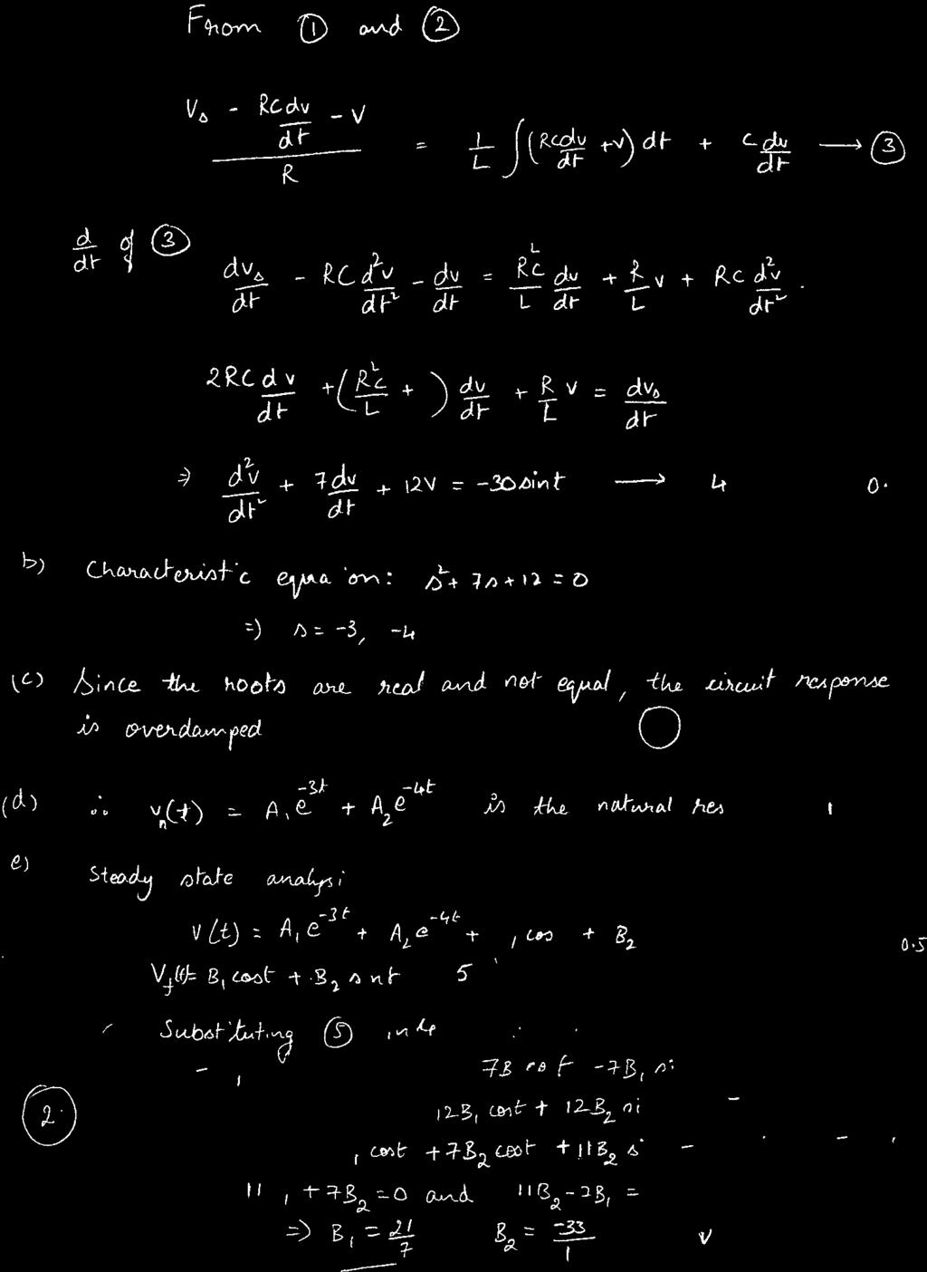
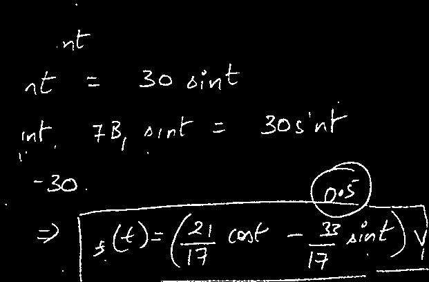
38 ECSE 10, Fall 013 NAME: Quiz # September 4, 013 ID: Read each question and its parts carefully before starting. Show all your work. Give units with your answers (where appropriate). 1. Consider the circuit diagram below. Assume that the circuit is at steady state at t = 0. [10pt] (a) Find the second-order differential equation governing v c (t) for t > 0. [3pt] (b) Is the system over-damped, under-damped, or critically damped? Why? [1pt] (c) Determine v c (t) for t > 0. [6pt] t=0 1 6 Ω 6V 3t V 4 Ω 1 H 1 / 13 F v c - 1
39 ECSE 10, Fall 013 Quiz # September 4, 013 Forcing Function Ke at Table 1: Forced Responses Assumed Response Ce at Kt n, n = 0, 1,,.. C n t n C n 1 t n 1... C 1 t C 0 K cos at C 1 cos at C sin at K sin at C 1 cos at C sin at Ke at cos bt e at (C 1 cos bt C sin bt) Ke ( at sin bt e at (C 1 cos bt C sin bt) n ) (( n ) ( n K i t i e at cos bt e at C i t i cos bt ( i=1 i=1 i=1 n ) (( n ) ( n K i t i e at sin bt e at C i t i cos bt i=1 Solution: Applying KVL at the right mesh: i=1 ) ) D i t i sin bt ) ) D i t i sin bt i=1 For the capacitor: 6i di dt v c = 3t [1pt] 1 dv c 13 dt = i Combining the two equations together: [1pt] d v c dt 6dv c dt 13v c = 39t Characteristic equation of the circuit: [1pt] λ 6λ 13 = 0 λ = 3 ± j under-damped [1pt] v c (t) = v cn (t) v cf (t) According to the characteristic equation, v n is: And the forced response is: v cn (t) = e 3t (A cos t B sin t) [1pt]
40 ECSE 10, Fall 013 Quiz # September 4, 013 t=0 1 i 6 Ω 6V 3t V 4 Ω 1 H 1 / 13 F v c - v f = Ct D [1pt] Finding C and D: Initial conditions: [1pt] d v cf dt 6 dv c f dt 13v cf = 39t 6C 13Ct 13D = 39t C = 3, D = v c (0 ) = v c (0 ) = 6; [1pt] i(0 ) = i(0 ) = 0; 1 dv c 13 dt (0 ) = i(0 ) = 0; dv c dt (0 ) = 0; Applying initial conditions: [1pt] v c (t) = e 3t (A cos t B sin t) 3t v(0 ) = 6 A = 6 A = dv(0 ) = 0 3A B 3 = 0 B = 49 dt 6 3
41 ECSE 10, Fall 013 Quiz # September 4, 013 And for t 0: v = e 3t ( cos t sin t) 3t [1pt] 4
Read each question and its parts carefully before starting. Show all your work. Give units with your answers (where appropriate).
.") ECSE 10, Fall 013 NAME: Quiz #1 September 17, 013 ID: Read each question and its parts carefully before starting. Show all your work. Give units with your answers (where appropriate). 1. Consider the circuit
ECSE 10, Fall 013 NAME: Quiz #1 September 17, 013 ID: Read each question and its parts carefully before starting. Show all your work. Give units with your answers (where appropriate). 1. Consider the circuit
Sinusoidal Steady State Analysis (AC Analysis) Part II
 Part II") Sinusoidal Steady State Analysis (AC Analysis) Part II Amin Electronics and Electrical Communications Engineering Department (EECE) Cairo University elc.n102.eng@gmail.com http://scholar.cu.edu.eg/refky/
Sinusoidal Steady State Analysis (AC Analysis) Part II Amin Electronics and Electrical Communications Engineering Department (EECE) Cairo University elc.n102.eng@gmail.com http://scholar.cu.edu.eg/refky/
EE 3120 Electric Energy Systems Study Guide for Prerequisite Test Wednesday, Jan 18, pm, Room TBA
 EE 3120 Electric Energy Systems Study Guide for Prerequisite Test Wednesday, Jan 18, 2006 6-7 pm, Room TBA First retrieve your EE2110 final and other course papers and notes! The test will be closed book
Sinusoidal Steady State Analysis
 Sinusoidal Steady State Analysis 9 Assessment Problems AP 9. [a] V = 70/ 40 V [b] 0 sin(000t +20 ) = 0 cos(000t 70 ).. I = 0/ 70 A [c] I =5/36.87 + 0/ 53.3 =4+j3+6 j8 =0 j5 =.8/ 26.57 A [d] sin(20,000πt
ECE 201 Fall 2009 Final Exam
 ECE 01 Fall 009 Final Exam December 16, 009 Division 0101: Tan (11:30am) Division 001: Clark (7:30 am) Division 0301: Elliott (1:30 pm) Instructions 1. DO NOT START UNTIL TOLD TO DO SO.. Write your Name,
REACTANCE. By: Enzo Paterno Date: 03/2013
 REACTANCE REACTANCE By: Enzo Paterno Date: 03/2013 5/2007 Enzo Paterno 1 RESISTANCE - R i R (t R A resistor for all practical purposes is unaffected by the frequency of the applied sinusoidal voltage or
EE 40: Introduction to Microelectronic Circuits Spring 2008: Midterm 2
 EE 4: Introduction to Microelectronic Circuits Spring 8: Midterm Venkat Anantharam 3/9/8 Total Time Allotted : min Total Points:. This is a closed book exam. However, you are allowed to bring two pages
Sinusoidal Steady State Analysis (AC Analysis) Part I
 Part I") Sinusoidal Steady State Analysis (AC Analysis) Part I Amin Electronics and Electrical Communications Engineering Department (EECE) Cairo University elc.n102.eng@gmail.com http://scholar.cu.edu.eg/refky/
Sinusoidal Steady State Analysis (AC Analysis) Part I Amin Electronics and Electrical Communications Engineering Department (EECE) Cairo University elc.n102.eng@gmail.com http://scholar.cu.edu.eg/refky/
Chapter 10: Sinusoids and Phasors
 Chapter 10: Sinusoids and Phasors 1. Motivation 2. Sinusoid Features 3. Phasors 4. Phasor Relationships for Circuit Elements 5. Impedance and Admittance 6. Kirchhoff s Laws in the Frequency Domain 7. Impedance
ECE Circuit Theory. Final Examination. December 5, 2008
 ECE 212 H1F Pg 1 of 12 ECE 212 - Circuit Theory Final Examination December 5, 2008 1. Policy: closed book, calculators allowed. Show all work. 2. Work in the provided space. 3. The exam has 3 problems
EE313 Fall 2013 Exam #1 (100 pts) Thursday, September 26, 2013 Name. 1) [6 pts] Convert the following time-domain circuit to the RMS Phasor Domain.
![EE313 Fall 2013 Exam #1 (100 pts) Thursday, September 26, 2013 Name. 1) [6 pts] Convert the following time-domain circuit to the RMS Phasor Domain.](/thumbs/95/123488230.jpg "EE313 Fall 2013 Exam #1 (100 pts) Thursday, September 26, 2013 Name. 1) [6 pts] Convert the following time-domain circuit to the RMS Phasor Domain.") Name If you have any questions ask them. Remember to include all units on your answers (V, A, etc). Clearly indicate your answers. All angles must be in the range 0 to +180 or 0 to 180 degrees. 1) [6 pts]
Name If you have any questions ask them. Remember to include all units on your answers (V, A, etc). Clearly indicate your answers. All angles must be in the range 0 to +180 or 0 to 180 degrees. 1) [6 pts]
Basics of Network Theory (Part-I)
") Basics of Network Theory (PartI). A square waveform as shown in figure is applied across mh ideal inductor. The current through the inductor is a. wave of peak amplitude. V 0 0.5 t (m sec) [Gate 987: Marks]
Basics of Network Theory (PartI). A square waveform as shown in figure is applied across mh ideal inductor. The current through the inductor is a. wave of peak amplitude. V 0 0.5 t (m sec) [Gate 987: Marks]
Sinusoidal Steady State Power Calculations
 10 Sinusoidal Steady State Power Calculations Assessment Problems AP 10.1 [a] V = 100/ 45 V, Therefore I = 20/15 A P = 1 (100)(20)cos[ 45 (15)] = 500W, 2 A B Q = 1000sin 60 = 866.03 VAR, B A [b] V = 100/
Fall 2011 ME 2305 Network Analysis. Sinusoidal Steady State Analysis of RLC Circuits
 Fall 2011 ME 2305 Network Analysis Chapter 4 Sinusoidal Steady State Analysis of RLC Circuits Engr. Humera Rafique Assistant Professor humera.rafique@szabist.edu.pk Faculty of Engineering (Mechatronics)
11. AC Circuit Power Analysis
 . AC Circuit Power Analysis Often an integral part of circuit analysis is the determination of either power delivered or power absorbed (or both). In this chapter First, we begin by considering instantaneous
ECE 421/521 Electric Energy Systems Power Systems Analysis I 2 Basic Principles. Instructor: Kai Sun Fall 2013
 ECE 41/51 Electric Energy Systems Power Systems Analysis I Basic Principles Instructor: Kai Sun Fall 013 1 Outline Power in a 1-phase AC circuit Complex power Balanced 3-phase circuit Single Phase AC System
Sinusoidal Steady-State Analysis
 Sinusoidal Steady-State Analysis Almost all electrical systems, whether signal or power, operate with alternating currents and voltages. We have seen that when any circuit is disturbed (switched on or
To find the step response of an RC circuit
 To find the step response of an RC circuit v( t) v( ) [ v( t) v( )] e tt The time constant = RC The final capacitor voltage v() The initial capacitor voltage v(t ) To find the step response of an RL circuit
Chapter 5 Steady-State Sinusoidal Analysis
 Chapter 5 Steady-State Sinusoidal Analysis Chapter 5 Steady-State Sinusoidal Analysis 1. Identify the frequency, angular frequency, peak value, rms value, and phase of a sinusoidal signal. 2. Solve steady-state
ECE Spring 2017 Final Exam
 ECE 20100 Spring 2017 Final Exam May 2, 2017 Section (circle below) Qi (12:30) 0001 Tan (10:30) 0004 Hosseini (7:30) 0005 Cui (1:30) 0006 Jung (11:30) 0007 Lin (9:30) 0008 Peleato-Inarrea (2:30) 0009 Name
Homework 2 SJTU233. Part A. Part B. Problem 2. Part A. Problem 1. Find the impedance Zab in the circuit seen in the figure. Suppose that R = 5 Ω.
 Homework 2 SJTU233 Problem 1 Find the impedance Zab in the circuit seen in the figure. Suppose that R = 5 Ω. Express Zab in polar form. Enter your answer using polar notation. Express argument in degrees.
EE292: Fundamentals of ECE
 EE292: Fundamentals of ECE Fall 2012 TTh 10:00-11:15 SEB 1242 Lecture 18 121025 http://www.ee.unlv.edu/~b1morris/ee292/ 2 Outline Review RMS Values Complex Numbers Phasors Complex Impedance Circuit Analysis
Sinusoids and Phasors
 CHAPTER 9 Sinusoids and Phasors We now begins the analysis of circuits in which the voltage or current sources are time-varying. In this chapter, we are particularly interested in sinusoidally time-varying
ECE Spring 2015 Final Exam
 ECE 20100 Spring 2015 Final Exam May 7, 2015 Section (circle below) Jung (1:30) 0001 Qi (12:30) 0002 Peleato (9:30) 0004 Allen (10:30) 0005 Zhu (4:30) 0006 Name PUID Instructions 1. DO NOT START UNTIL
Sinusoidal Steady-State Analysis
 Chapter 4 Sinusoidal Steady-State Analysis In this unit, we consider circuits in which the sources are sinusoidal in nature. The review section of this unit covers most of section 9.1 9.9 of the text.
Phasors: Impedance and Circuit Anlysis. Phasors
 Phasors: Impedance and Circuit Anlysis Lecture 6, 0/07/05 OUTLINE Phasor ReCap Capacitor/Inductor Example Arithmetic with Complex Numbers Complex Impedance Circuit Analysis with Complex Impedance Phasor
Lecture (5) Power Factor,threephase circuits, and Per Unit Calculations
 Power Factor,threephase circuits, and Per Unit Calculations") Lecture (5) Power Factor,threephase circuits, and Per Unit Calculations 5-1 Repeating the Example on Power Factor Correction (Given last Class) P? Q? S? Light Motor From source 1000 volts @ 60 Htz 10kW
Lecture (5) Power Factor,threephase circuits, and Per Unit Calculations 5-1 Repeating the Example on Power Factor Correction (Given last Class) P? Q? S? Light Motor From source 1000 volts @ 60 Htz 10kW
= 32.0\cis{38.7} = j Ω. Zab = Homework 2 SJTU233. Part A. Part B. Problem 2. Part A. Problem 1
 Homework 2 SJTU233 Problem 1 Find the impedance Zab in the circuit seen in the figure. Suppose that R = 5 Ω. Express Zab in polar form. Enter your answer using polar notation. Express argument in degrees.
AC Circuits Homework Set
 Problem 1. In an oscillating LC circuit in which C=4.0 μf, the maximum potential difference across the capacitor during the oscillations is 1.50 V and the maximum current through the inductor is 50.0 ma.
EE221 - Practice for the Midterm Exam
 EE1 - Practice for the Midterm Exam 1. Consider this circuit and corresponding plot of the inductor current: Determine the values of L, R 1 and R : L = H, R 1 = Ω and R = Ω. Hint: Use the plot to determine
Figure Circuit for Question 1. Figure Circuit for Question 2
 Exercises 10.7 Exercises Multiple Choice 1. For the circuit of Figure 10.44 the time constant is A. 0.5 ms 71.43 µs 2, 000 s D. 0.2 ms 4 Ω 2 Ω 12 Ω 1 mh 12u 0 () t V Figure 10.44. Circuit for Question
Source-Free RC Circuit
 First Order Circuits Source-Free RC Circuit Initial charge on capacitor q = Cv(0) so that voltage at time 0 is v(0). What is v(t)? Prof Carruthers (ECE @ BU) EK307 Notes Summer 2018 150 / 264 First Order
Three Phase Circuits
 Amin Electronics and Electrical Communications Engineering Department (EECE) Cairo University elc.n102.eng@gmail.com http://scholar.cu.edu.eg/refky/ OUTLINE Previously on ELCN102 Three Phase Circuits Balanced
Chapter 9 Objectives
 Chapter 9 Engr8 Circuit Analysis Dr Curtis Nelson Chapter 9 Objectives Understand the concept of a phasor; Be able to transform a circuit with a sinusoidal source into the frequency domain using phasor
Chapter 10 Sinusoidal Steady State Analysis Chapter Objectives:
 Chapter 10 Sinusoidal Steady State Analysis Chapter Objectives: Apply previously learn circuit techniques to sinusoidal steady-state analysis. Learn how to apply nodal and mesh analysis in the frequency
Chapter 10: Sinusoidal Steady-State Analysis
 Chapter 10: Sinusoidal Steady-State Analysis 1 Objectives : sinusoidal functions Impedance use phasors to determine the forced response of a circuit subjected to sinusoidal excitation Apply techniques
Electric Circuit Theory
 Electric Circuit Theory Nam Ki Min nkmin@korea.ac.kr 010-9419-2320 Chapter 11 Sinusoidal Steady-State Analysis Nam Ki Min nkmin@korea.ac.kr 010-9419-2320 Contents and Objectives 3 Chapter Contents 11.1
Electric Circuit Theory
 Electric Circuit Theory Nam Ki Min nkmin@korea.ac.kr 010-9419-2320 Chapter 8 Natural and Step Responses of RLC Circuits Nam Ki Min nkmin@korea.ac.kr 010-9419-2320 8.1 Introduction to the Natural Response
ECE 212H1F Circuit Analysis October 30, :10-19: Reza Iravani 02 Reza Iravani 03 Piero Triverio. (Non-programmable Calculators Allowed)
") Please Print Clearly Last Name: First Name: Student Number: Your Tutorial Section (CIRCLE ONE): 01 Thu. 9-11 RS211 02 Thu. 9-11 GB119 03 Tue. 10-12 SF2202 04 Tue. 10-12 SF3201 05 Tue. 13-15 GB304 06 Tue.
Please Print Clearly Last Name: First Name: Student Number: Your Tutorial Section (CIRCLE ONE): 01 Thu. 9-11 RS211 02 Thu. 9-11 GB119 03 Tue. 10-12 SF2202 04 Tue. 10-12 SF3201 05 Tue. 13-15 GB304 06 Tue.
mywbut.com Lesson 16 Solution of Current in AC Parallel and Seriesparallel
 esson 6 Solution of urrent in Parallel and Seriesparallel ircuits n the last lesson, the following points were described:. How to compute the total impedance/admittance in series/parallel circuits?. How
ECE 420. Review of Three Phase Circuits. Copyright by Chanan Singh, Panida Jirutitijaroen, and Hangtian Lei, For educational use only-not for sale.
 ECE 40 Review of Three Phase Circuits Outline Phasor Complex power Power factor Balanced 3Ф circuit Read Appendix A Phasors and in steady state are sinusoidal functions with constant frequency 5 0 15 10
BASIC PRINCIPLES. Power In Single-Phase AC Circuit
 BASIC PRINCIPLES Power In Single-Phase AC Circuit Let instantaneous voltage be v(t)=v m cos(ωt+θ v ) Let instantaneous current be i(t)=i m cos(ωt+θ i ) The instantaneous p(t) delivered to the load is p(t)=v(t)i(t)=v
EE292: Fundamentals of ECE
 EE292: Fundamentals of ECE Fall 2012 TTh 10:00-11:15 SEB 1242 Lecture 20 121101 http://www.ee.unlv.edu/~b1morris/ee292/ 2 Outline Chapters 1-3 Circuit Analysis Techniques Chapter 10 Diodes Ideal Model
ENGR 2405 Chapter 8. Second Order Circuits
 ENGR 2405 Chapter 8 Second Order Circuits Overview The previous chapter introduced the concept of first order circuits. This chapter will expand on that with second order circuits: those that need a second
Module 4. Single-phase AC Circuits
 Module 4 Single-phase AC Circuits Lesson 14 Solution of Current in R-L-C Series Circuits In the last lesson, two points were described: 1. How to represent a sinusoidal (ac) quantity, i.e. voltage/current
Electric Circuits I FINAL EXAMINATION
 EECS:300, Electric Circuits I s6fs_elci7.fm - Electric Circuits I FINAL EXAMINATION Problems Points.. 3. 0 Total 34 Was the exam fair? yes no 5//6 EECS:300, Electric Circuits I s6fs_elci7.fm - Problem
EE292: Fundamentals of ECE
 EE292: Fundamentals of ECE Fall 2012 TTh 10:00-11:15 SEB 1242 Lecture 14 121011 http://www.ee.unlv.edu/~b1morris/ee292/ 2 Outline Review Steady-State Analysis RC Circuits RL Circuits 3 DC Steady-State
LO 1: Three Phase Circuits
 Course: EEL 2043 Principles of Electric Machines Class Instructor: Dr. Haris M. Khalid Email: hkhalid@hct.ac.ae Webpage: www.harismkhalid.com LO 1: Three Phase Circuits Three Phase AC System Three phase
Chapter 3 : Linear Differential Eqn. Chapter 3 : Linear Differential Eqn.
 1.0 Introduction Linear differential equations is all about to find the total solution y(t), where : y(t) = homogeneous solution [ y h (t) ] + particular solution y p (t) General form of differential equation
09/29/2009 Reading: Hambley Chapter 5 and Appendix A
 EE40 Lec 10 Complex Numbers and Phasors Prof. Nathan Cheung 09/29/2009 Reading: Hambley Chapter 5 and Appendix A Slide 1 OUTLINE Phasors as notation for Sinusoids Arithmetic with Complex Numbers Complex
Two-Port Networks Admittance Parameters CHAPTER16 THE LEARNING GOALS FOR THIS CHAPTER ARE THAT STUDENTS SHOULD BE ABLE TO:
 CHAPTER16 Two-Port Networks THE LEARNING GOALS FOR THIS CHAPTER ARE THAT STUDENTS SHOULD BE ABLE TO: Calculate the admittance, impedance, hybrid, and transmission parameter for two-port networks. Convert
Introduction to AC Circuits (Capacitors and Inductors)
") Introduction to AC Circuits (Capacitors and Inductors) Amin Electronics and Electrical Communications Engineering Department (EECE) Cairo University elc.n102.eng@gmail.com http://scholar.cu.edu.eg/refky/
Introduction to AC Circuits (Capacitors and Inductors) Amin Electronics and Electrical Communications Engineering Department (EECE) Cairo University elc.n102.eng@gmail.com http://scholar.cu.edu.eg/refky/
Basics of Electric Circuits
 António Dente Célia de Jesus February 2014 1 Alternating Current Circuits 1.1 Using Phasors There are practical and economic reasons justifying that electrical generators produce emf with alternating and
ECE2262 Electric Circuits. Chapter 6: Capacitance and Inductance
 ECE2262 Electric Circuits Chapter 6: Capacitance and Inductance Capacitors Inductors Capacitor and Inductor Combinations Op-Amp Integrator and Op-Amp Differentiator 1 CAPACITANCE AND INDUCTANCE Introduces
GATE 20 Years. Contents. Chapters Topics Page No.
 GATE 0 Years Contents Chapters Topics Page No. Chapter- Chapter- Chapter- Chapter-4 Chapter-5 GATE Syllabus for this Chapter Topic elated to Syllabus Previous 0-Years GATE Questions Previous 0-Years GATE
ECE 476 Power System Analysis Fall 2014 Exam #1, Thursday, October 2, :30AM - 10:50AM
 ECE 476 Power System Analysis Fall 4 Exam #, Thursday, October, 4. 9:3AM - :5AM Name: Problem (5 p) Two balanced 3-phase loads are connected in parallel. One is Y-connected and draws 75 kw (3-phase) at.8
Electric Circuits II Sinusoidal Steady State Analysis. Dr. Firas Obeidat
 Electric Circuits II Sinusoidal Steady State Analysis Dr. Firas Obeidat 1 Table of Contents 1 2 3 4 5 Nodal Analysis Mesh Analysis Superposition Theorem Source Transformation Thevenin and Norton Equivalent
Review of DC Electric Circuit. DC Electric Circuits Examples (source:
 Review of DC Electric Circuit DC Electric Circuits Examples (source: http://hyperphysics.phyastr.gsu.edu/hbase/electric/dcex.html) 1 Review - DC Electric Circuit Multisim Circuit Simulation DC Circuit
Lecture 11 - AC Power
 - AC Power 11/17/2015 Reading: Chapter 11 1 Outline Instantaneous power Complex power Average (real) power Reactive power Apparent power Maximum power transfer Power factor correction 2 Power in AC Circuits
CIRCUIT ANALYSIS II. (AC Circuits)
") Will Moore MT & MT CIRCUIT ANALYSIS II (AC Circuits) Syllabus Complex impedance, power factor, frequency response of AC networks including Bode diagrams, second-order and resonant circuits, damping and
Will Moore MT & MT CIRCUIT ANALYSIS II (AC Circuits) Syllabus Complex impedance, power factor, frequency response of AC networks including Bode diagrams, second-order and resonant circuits, damping and
Sinusoidal Response of RLC Circuits
 Sinusoidal Response of RLC Circuits Series RL circuit Series RC circuit Series RLC circuit Parallel RL circuit Parallel RC circuit R-L Series Circuit R-L Series Circuit R-L Series Circuit Instantaneous
8. Introduction and Chapter Objectives
 Real Analog - Circuits Chapter 8: Second Order Circuits 8. Introduction and Chapter Objectives Second order systems are, by definition, systems whose input-output relationship is a second order differential
Chapter 33. Alternating Current Circuits
 Chapter 33 Alternating Current Circuits 1 Capacitor Resistor + Q = C V = I R R I + + Inductance d I Vab = L dt AC power source The AC power source provides an alternative voltage, Notation - Lower case
Schedule. ECEN 301 Discussion #20 Exam 2 Review 1. Lab Due date. Title Chapters HW Due date. Date Day Class No. 10 Nov Mon 20 Exam Review.
 Schedule Date Day lass No. 0 Nov Mon 0 Exam Review Nov Tue Title hapters HW Due date Nov Wed Boolean Algebra 3. 3.3 ab Due date AB 7 Exam EXAM 3 Nov Thu 4 Nov Fri Recitation 5 Nov Sat 6 Nov Sun 7 Nov Mon
12. Introduction and Chapter Objectives
 Real Analog - Circuits 1 Chapter 1: Steady-State Sinusoidal Power 1. Introduction and Chapter Objectives In this chapter we will address the issue of power transmission via sinusoidal or AC) signals. This
Note 11: Alternating Current (AC) Circuits
 Circuits") Note 11: Alternating Current (AC) Circuits V R No phase difference between the voltage difference and the current and max For alternating voltage Vmax sin t, the resistor current is ir sin t. the instantaneous
Note 11: Alternating Current (AC) Circuits V R No phase difference between the voltage difference and the current and max For alternating voltage Vmax sin t, the resistor current is ir sin t. the instantaneous
04-Electric Power. ECEGR 452 Renewable Energy Systems
 04-Electric Power ECEGR 452 Renewable Energy Systems Overview Review of Electric Circuits Phasor Representation Electrical Power Power Factor Dr. Louie 2 Introduction Majority of the electrical energy
Module 4. Single-phase AC circuits. Version 2 EE IIT, Kharagpur
 Module 4 Single-phase circuits ersion EE T, Kharagpur esson 6 Solution of urrent in Parallel and Seriesparallel ircuits ersion EE T, Kharagpur n the last lesson, the following points were described:. How
ECEN 460 Exam 1 Fall 2018
 ECEN 460 Exam 1 Fall 2018 Name: KEY UIN: Section: Score: Part 1 / 40 Part 2 / 0 Part / 0 Total / 100 This exam is 75 minutes, closed-book, closed-notes. A standard calculator and one 8.5 x11 note sheet
4/27 Friday. I have all the old homework if you need to collect them.
 4/27 Friday Last HW: do not need to turn it. Solution will be posted on the web. I have all the old homework if you need to collect them. Final exam: 7-9pm, Monday, 4/30 at Lambert Fieldhouse F101 Calculator
Lecture 05 Power in AC circuit
 CA2627 Building Science Lecture 05 Power in AC circuit Instructor: Jiayu Chen Ph.D. Announcement 1. Makeup Midterm 2. Midterm grade Grade 25 20 15 10 5 0 10 15 20 25 30 35 40 Grade Jiayu Chen, Ph.D. 2
Solved Problems. Electric Circuits & Components. 1-1 Write the KVL equation for the circuit shown.
 Solved Problems Electric Circuits & Components 1-1 Write the KVL equation for the circuit shown. 1-2 Write the KCL equation for the principal node shown. 1-2A In the DC circuit given in Fig. 1, find (i)
Chapter 10 AC Analysis Using Phasors
 Chapter 10 AC Analysis Using Phasors 10.1 Introduction We would like to use our linear circuit theorems (Nodal analysis, Mesh analysis, Thevenin and Norton equivalent circuits, Superposition, etc.) to
Chapter 1W Basic Electromagnetic Concepts
 Chapter 1W Basic Electromagnetic Concepts 1W Basic Electromagnetic Concepts 1W.1 Examples and Problems on Electric Circuits 1W.2 Examples on Magnetic Concepts This chapter includes additional examples
Power Systems - Basic Concepts and Applications - Part I
 PDHonline Course E104 (1 PDH) Power ystems Basic Concepts and Applications Part I Instructor: hihmin Hsu PhD PE 01 PDH Online PDH Center 57 Meadow Estates Drive Fairfax A 006658 Phone & Fax: 709880088
BFF1303: ELECTRICAL / ELECTRONICS ENGINEERING. Alternating Current Circuits : Basic Law
 BFF1303: ELECTRICAL / ELECTRONICS ENGINEERING Alternating Current Circuits : Basic Law Ismail Mohd Khairuddin, Zulkifil Md Yusof Faculty of Manufacturing Engineering Universiti Malaysia Pahang Alternating
Problem Set 5 Solutions
 University of California, Berkeley Spring 01 EE /0 Prof. A. Niknejad Problem Set 5 Solutions Please note that these are merely suggested solutions. Many of these problems can be approached in different
EIT Quick-Review Electrical Prof. Frank Merat
 CIRCUITS 4 The power supplied by the 0 volt source is (a) 2 watts (b) 0 watts (c) 2 watts (d) 6 watts (e) 6 watts 4Ω 2Ω 0V i i 2 2Ω 20V Call the clockwise loop currents i and i 2 as shown in the drawing
SINUSOIDAL STEADY STATE CIRCUIT ANALYSIS
 SINUSOIDAL STEADY STATE CIRCUIT ANALYSIS 1. Introduction A sinusoidal current has the following form: where I m is the amplitude value; ω=2 πf is the angular frequency; φ is the phase shift. i (t )=I m.sin
Boise State University Department of Electrical and Computer Engineering ECE 212L Circuit Analysis and Design Lab
 Objectives Boise State University Department of Electrical and Computer Engineering ECE 22L Circuit Analysis and Design Lab Experiment #4: Power Factor Correction The objectives of this laboratory experiment
ELECTRONICS E # 1 FUNDAMENTALS 2/2/2011
 FE Review 1 ELECTRONICS E # 1 FUNDAMENTALS Electric Charge 2 In an electric circuit it there is a conservation of charge. The net electric charge is constant. There are positive and negative charges. Like
f = 1 T 6 a.c. (Alternating Current) Circuits Most signals of interest in electronics are periodic : they repeat regularly as a function of time.
 Circuits Most signals of interest in electronics are periodic : they repeat regularly as a function of time.") Analogue Electronics (Aero).66 66 Analogue Electronics (Aero) 6.66 6 a.c. (Alternating Current) Circuits Most signals of interest in electronics are periodic : they repeat regularly as a function of time.
Analogue Electronics (Aero).66 66 Analogue Electronics (Aero) 6.66 6 a.c. (Alternating Current) Circuits Most signals of interest in electronics are periodic : they repeat regularly as a function of time.
Module 4. Single-phase AC Circuits. Version 2 EE IIT, Kharagpur 1
 Module 4 Single-phase A ircuits ersion EE IIT, Kharagpur esson 4 Solution of urrent in -- Series ircuits ersion EE IIT, Kharagpur In the last lesson, two points were described:. How to represent a sinusoidal
An op amp consisting of a complex arrangement of resistors, transistors, capacitors, and diodes. Here, we ignore the details.
 CHAPTER 5 Operational Amplifiers In this chapter, we learn how to use a new circuit element called op amp to build circuits that can perform various kinds of mathematical operations. Op amp is a building
EECE 2150 Circuits and Signals, Biomedical Applications Final Exam Section 3
 EECE 2150 Circuits and Signals, Biomedical Applications Final Exam Section 3 Instructions: Closed book, closed notes; Computers and cell phones are not allowed You may use the equation sheet provided but
Linear Circuits. Concept Map 9/10/ Resistive Background Circuits. 5 Power. 3 4 Reactive Circuits. Frequency Analysis
 Linear Circuits Dr. Bonnie Ferri Professor School of Electrical and Computer Engineering An introduction to linear electric components and a study of circuits containing such devices. School of Electrical
Response of Second-Order Systems
 Unit 3 Response of SecondOrder Systems In this unit, we consider the natural and step responses of simple series and parallel circuits containing inductors, capacitors and resistors. The equations which
GATE : , Copyright reserved. Web:www.thegateacademy.com
 GATE-2016 Index 1. Question Paper Analysis 2. Question Paper & Answer keys : 080-617 66 222, info@thegateacademy.com Copyright reserved. Web:www.thegateacademy.com ANALYSIS OF GATE 2016 Electrical Engineering
Circuit Analysis-III. Circuit Analysis-II Lecture # 3 Friday 06 th April, 18
 Circuit Analysis-III Sinusoids Example #1 ü Find the amplitude, phase, period and frequency of the sinusoid: v (t ) =12cos(50t +10 ) Signal Conversion ü From sine to cosine and vice versa. ü sin (A ± B)
University of Toronto Faculty of Applied Science and Engineering. ECE212H1F - Circuit Analysis. Final Examination December 16, :30am - noon
 , LAST name: First name: Student ID: University of Toronto Faculty of Applied Science and Engineering ECE212H1F - Circuit Analysis Final Examination December 16, 2017 9:30am - noon Guidelines: Exam type:
MAT292 - Calculus III - Fall Solution for Term Test 2 - November 6, 2014 DO NOT WRITE ON THE QR CODE AT THE TOP OF THE PAGES.
 MAT9 - Calculus III - Fall 4 Solution for Term Test - November 6, 4 Time allotted: 9 minutes. Aids permitted: None. Full Name: Last First Student ID: Email: @mail.utoronto.ca Instructions DO NOT WRITE
Designing Information Devices and Systems II Spring 2016 Anant Sahai and Michel Maharbiz Midterm 2
 EECS 16B Designing Information Devices and Systems II Spring 2016 Anant Sahai and Michel Maharbiz Midterm 2 Exam location: 145 Dwinelle (SIDs ending in 1 and 5) PRINT your student ID: PRINT AND SIGN your
ECE 421/521 Electric Energy Systems Power Systems Analysis I 2 Basic Principles. Instructor: Kai Sun Fall 2014
 ECE 41/51 Electric Energy Systems Power Systems Analysis I Basic Princiles Instructor: Kai Sun Fall 014 1 Outline Power in a 1-hase AC circuit Comlex ower Balanced 3-hase circuit Single Phase AC System
R-L-C Circuits and Resonant Circuits
 P517/617 Lec4, P1 R-L-C Circuits and Resonant Circuits Consider the following RLC series circuit What's R? Simplest way to solve for is to use voltage divider equation in complex notation. X L X C in 0
ECE Linear Circuit Analysis II
 ECE 202 - Linear Circuit Analyi II Final Exam Solution December 9, 2008 Solution Breaking F into partial fraction, F 2 9 9 + + 35 9 ft δt + [ + 35e 9t ]ut A 9 Hence 3 i the correct anwer. Solution 2 ft
Circuits. Fawwaz T. Ulaby, Michel M. Maharbiz, Cynthia M. Furse. Solutions to the Exercises
 Circuits by Fawwaz T. Ulaby, Michel M. Maharbiz, Cynthia M. Furse Solutions to the Exercises Chapter 1: Circuit Terminology Chapter 2: Resisitive Circuits Chapter 3: Analysis Techniques Chapter 4: Operational
ECE2262 Electric Circuit
 ECE2262 Electric Circuit Chapter 7: FIRST AND SECOND-ORDER RL AND RC CIRCUITS Response to First-Order RL and RC Circuits Response to Second-Order RL and RC Circuits 1 2 7.1. Introduction 3 4 In dc steady
ELEC 2501 AB. Come to the PASS workshop with your mock exam complete. During the workshop you can work with other students to review your work.
 It is most beneficial to you to write this mock midterm UNDER EXAM CONDITIONS. This means: Complete the midterm in 3 hour(s). Work on your own. Keep your notes and textbook closed. Attempt every question.
ECE2262 Electric Circuits. Chapter 6: Capacitance and Inductance
 ECE2262 Electric Circuits Chapter 6: Capacitance and Inductance Capacitors Inductors Capacitor and Inductor Combinations 1 CAPACITANCE AND INDUCTANCE Introduces two passive, energy storing devices: Capacitors
Revised October 6, EEL , Henry Zmuda. 2. Three-Phase Circuits 1
 Three Phase Circuitsit Revised October 6, 008. Three-Phase Circuits 1 Preliminary Comments and a quick review of phasors. We live in the time domain. We also assume a causal (nonpredictive) world. Real-world