DU67 Tube Microphone
|
|
|
- Amos Claude Newton
- 5 years ago
- Views:
Transcription

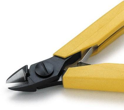
1 DU67 Tube Microphone

2


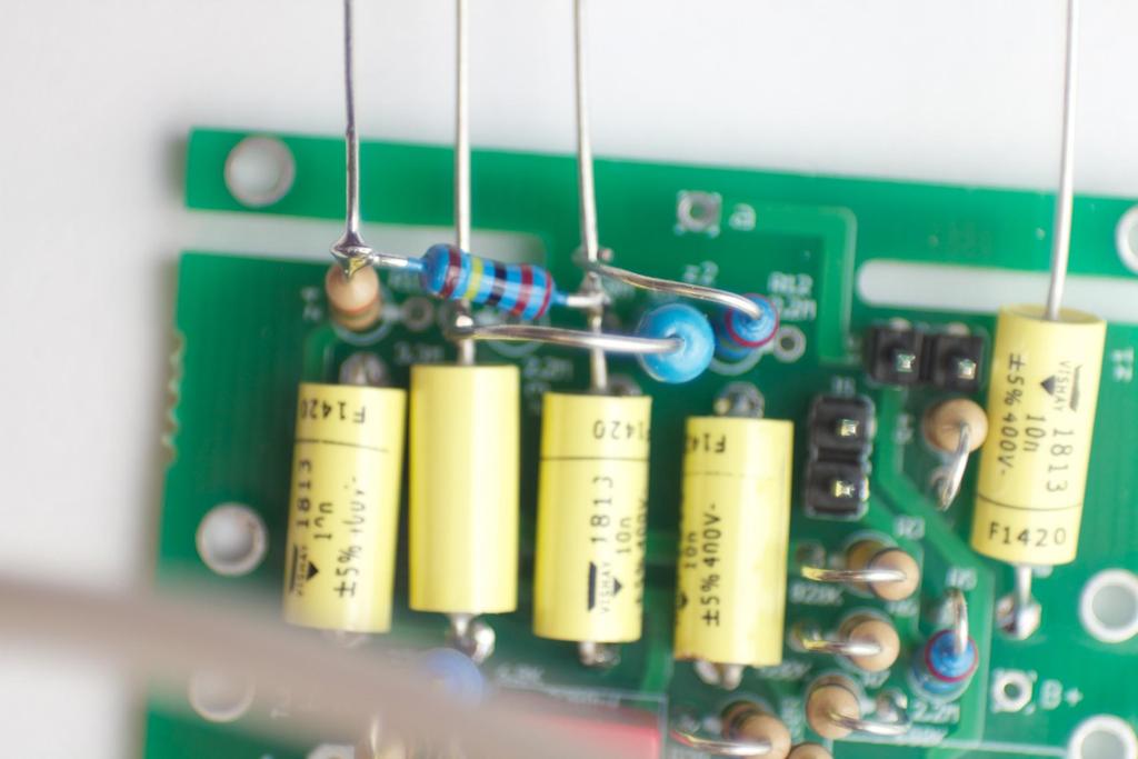
3 M ai n PCB. Don't instal the following parts yet: R1 5,R1 3,R9,R1 2,C7,C4,C2 and C1 7 **** Don 't u se th e h ol es m aked i n red Start By I nstalling the parts that are shown to the left. I like to stuff all the parts, bending the lead s on the bottom such that they are not overlapping other traces to avoid any brid ging. Cl i p al l of th e l ead s of th e i n stal l ed parts, th en sol d er.
 is built in the air.")

4 The next few parts will be installed so that the High Z (impedance) is built in the air. This will ensure a low noise build. I n stal l C7 Leave th e top l ead strai g h t an d u n -sol d ered I n stal l C4 Leave th e top l ead strai g h t an d u n -sol d ered


5 I n stal l C2 Leave th e top l ead strai g h t an d u n soldered I n stal l R1 5 Leave th e top l ead strai g h t an d u n sol d ered

6 Ben d th e lead of R13 Tri m th e lead of R1 3. Do th i s to both si d es.


7 Sol d er R1 3 to C4 an d R1 5 Install R9 in the hole with the circle arou nd it then solder. Bend the lead towards C7


8 Form a Hook on R9 Hook the one end of R9 to the end of C7 and solder.


9 Do the same for R1 2 an d sol der the hooked end to C4
10
11 Use the drawing below to install tube socket parts. The silkscreen may confuse you. Notice that the colors match the colors on the schematic on the following page.


12 I n stal l th e insulated tu rrets by pressi n g th em i n to th e h ol e circled i n red
 to solder the tube")

13 When installing th e parts on th e top si d e of th e Tube Socket PCB, be sure to l eave en ou g h room (¼ or 6mm ) to solder the tube socket. *** N ote: Tu be socket sh own for reference on l y. Don t in stal l tu be socket yet. I n stal l C8 an d R1 clip the leads and solder

14 Prepare R2 by form i n g a h ook on one en d. Leave The Other en d l on g Solder th e hook to th e Turret as shown


15 Prepare C1 Leave the other end long. This will get connected to the Tube socket Install R1 6 but leave one end long. This long lead is coded red on the schematic

 cap until after clean ing the flux off is done I")
16 Prepare R8 by forming a loop on one end around the other turret. Leave the other end long. If you plan on cleaning off the flux, don't install C1 0 (styroflex) cap until after clean ing the flux off is done I n stal l tu be socket an d sol d er


17 Form a 90 d eg re an g l e of C1 toward s the grid pi n Bend th e lead down towards the tube socket pi n


18 Cl i p the lead of C1 and solder to the tube socket pin

19 Form a 90 degree angle of R8 towards the grid pin. Form a hook. trim and solder
20 BLU E RED YELLOW


21 RED BLU E YELLOW BLU E RED GREEN YELLOW GREEN


22 I n sert th e Tu be Socket PCB i n to th e sl ot on th e main PCB Sol d er on e set of pad s su ch th at th e two PCBs form a ri g h t an g l e. ****Don't try to "bend" the angle without reflowing the solder joint. Now solder th e two remaining joints circled i n red


23 Form a 90 d eg re an g l e with R2 toward s C4 (yellow n et) Form a hook. trim and solder

 Tri m an d sol d")
24 Form a 90 d eg re an g l e of C2 toward s th e Backpl ate tu rret. Form a hook around the Backplate tu rret (g reen n et) Tri m an d sol d er

25 Con n ect C7 (bl u e n et) an d R8 by form i n g inter connecting h ooks. Trim an d sol d er. Form a ri g h t an g l e wi th th e l on g l ead of R1 6 toward s R1 5. J oi n R1 5 an d R16 (red n et) by form i n g i n tercon n ecti n g h ooks. Tri m an d sol d er.


26 Solder To Link HZ Bridge Reference

27 Install C10 Solder from top Pad on tube Socket PCB and then to grid turret


28 Find the three position switch and install in the "PAT position and solder. Take care to solder the Switches so they are flush to the PCB and aligned to the silkscreen I n stal l th e rem ai n g swi tch es (two posi \tion ) an d sol d er. Test fi t th e switch PCB i n th e assembled m i c bod y. M ake su re th e pattern switch i n not obstructed by th e m i c bod y


29 Sol d er si x d i fferen t col ored wi res as sh own. (abou t 3 i n ch es l on g ) Solder the rear diaphragm wire to the other side.

30 REFERENCE PAD SWI TCH REAR CAPSU LE M ODI FI ED RAI L LOW CU T SWI TCH COM PON EN T SI DE OF PCB PATTERN SWI TCH FRON T CAPSU LE

31 Backplate Back

32 Feed th e rear capsule wi re through the si n g l e one of th e center h ol es. Attach switch PCB With the 3 screws and standoffs. Install m ai n m i c PCBs i n to m i c bod y on th e Same side of th e rai l th at h as been modified to fit AM I T67 tran sform er.

33 Feed the backplate wire from the Switch PCB and tri m to length. Leave some slack. Strip the en d, tin with solder, an d form a hook.


34 Solder Backplate wire to the insulated turret. Feed th e PAD wi re from th e Swi tch PCB an d tri m to l en g th. Leave som e sl ack. Stri p th e en d, ti n wi th sol d er, an d i n stal l, an d sol d er to PCB


35 Trim the Low Cut wires to length. Strip the ends back, tin with solder. Solder to two pin header labeled "LC" Trim the Omni wire from the "PAT" switch to length. Form a hook and install to the Front diaphragm turret.
36 Tri m th e Bl u e Fi g u re 8 wi re to l en g th. Stri p th e en d s back, tin wi th sol d er. I n stal l an d sol d er to the h ol e ci rcl ed i n red bel ow.


37 Cu t two m ore wi res to abou t 2-3 i n ch es l on g. Sol der one to th e Front d i aph ram capsule tu rret an d ru n u p th rou g h the capsule m ou n ti n g base. Do th i s th e same for th e backplate wi re an d rear capsule wi re. Carefu l l y I n stal l th e capsu l e. Cover the d i aph ram to protect it from th e sol d eri n g process. H eat an d fl u x can ru i n a capsu l e. Th i s i s very important. Now Careful l y sol d er th e three wires to th e capsu l e.


38 Remove the 7 pin XLR connector from the bottom of the mic body by turning the screw clockwise. You may have to push it out from the inside of the mic. You can cut a section from your tube mic cable for the internal wiring. Teflon insulation wire is better because the insulation won' t melt when soldering. Use this wiring chart for XLR pin-out. to tube mic. Cut about 3 inches of wire. Strip, tin and solder to Male XLR connector.


39 It should look similar to this after soldering. I t's a g ood i d ea to h eatsh ri n k th e wi res.


40 The AMI T67 transformer is a tad too big for the mic rails. Remove the head basket. Remove the bottom four screws to remove the XLR/ shock mount base. Use your favorite tool (My favorite is a 4 Inch angle grinder) or Dremel to grind away part of the rail. Test fit the T67 transformer and PCB to the Mic rails. Make sure there is clearance between the laminations and the rails.

41 Install the T67 transformer to the adapter PCB. Be sure to align the black mark on the transformer to the marking circled in red on the PCB.


42 Verify that the black making on the transformer and the marking on the PCB are located inside the red circle. Solder the transformer to the PCB. Screw the transformer PCB to the rails. Feed the wires between the transformer and PCB as shown. Attach the base to the rails with the four screws.


43 Trim and Solder the XLR wires to the Mic PCB


44 Sol d er wires as sh own ~2 i n ch es l on g to th e tran sform er PCB. Solder "1 " on the transf. PCB to "T44" on Main PCB Solder "7" to "T1 01 0" Solder "5" to "T1 21 2" Solder "1 2" to "T55" Solder "1 0" to "T77" Sol d er "4" to "T1 1 "
45 Now you should have eveyth ing soldered on the PSU and the Mic. En su re th at th e m i c i s u n pl u g g ed from th e PSU. Appl y power to th e PSU. Ch eck vol tag es at th e AC i n pu t of th e PSU PCB. 20VAC for th e h eater ~270VAC at th e H T i n pu t N ow Ch eck DC vol tag es. Unloaded, my mic meau sres -1 6VDC at H- and 250VDC at B+ If your Voltages check out, power down the PSU, plug in the Mic Do not install the tube. Turn on the PSU. Check Voltages at H- B+ on the mic. Use the screw mounting holes as Gnd ref. Voltages should be very close to the read ings at the PSU. Verify that there is less than one ohm between the mic body and the chassis of the PSU Turn off the PSU. turn down the pots on the PSU to the highest resistance settings. Install the EF86 tube (you can use a cheap one for setting voltages. Be carefu ll to not disturb the wiring at n ear the
46 Check the voltages at the mic with the tube installed and the PSU turned on. The voltage will start high and drop as the tube warms up. Ch eck th e B+ Vol tag e. I t sh ou l d be j u st u n d er 21 0VDC Check the H- Voltage. It should be arou nd -6.3V (negative) I t's a g ood i d ea to be u n d er vol tag e by a few vol ts. Let the tube warm u p for about 20 minutes N ow ad j u st th e vol tag es u si n g th e pots i n th e PSU. Ad just Rtrim H - until you reach -6. 3VDC Ad j u st Rtri m Pl ate u n ti l B+ read s 21 0VDC Con ti n u e to m on i tor th e vol tag es an d peri od i cl y sm el l th e el ectron i cs for an yth i n g th at sm el l s. Don 't l et th e m ag i c sm oke out! Power off th e m i c. In stall th e bod y Power on the mic and check the LC, Pad, and pattern switches by listen ing through a mic preamp and headphones as you toggle the switches. You should now be pleasantly suprised with the great sound of your voice through a tube mic, Enjoy!
FLT5A FLT5A. abc. abc. Thermometer User Guide. Thermometer User Guide. Internet:
 abc instruments international FLT5A Thermometer Land Instruments International Dronfield, S18 1DJ England Telephone: (1246) 417691 Facsimile: (1246) 41585 Email: infrared.sales@landinst.com Internet: www.landinst.com
OH BOY! Story. N a r r a t iv e a n d o bj e c t s th ea t e r Fo r a l l a g e s, fr o m th e a ge of 9
 OH BOY! O h Boy!, was or igin a lly cr eat ed in F r en ch an d was a m a jor s u cc ess on t h e Fr en ch st a ge f or young au di enc es. It h a s b een s een by ap pr ox i ma t ely 175,000 sp ect at
MAIN PCB R10, 12k R31. 2) Now with the capacitors. C12,C7 C20 C6. 1N4148 D3, D5, D6 Zener 4v7 D1, D D4, D7 ferrites F1+, F2- 4) Transistors
 Now with the capacitors. C12,C7 C20 C6. 1N4148 D3, D5, D6 Zener 4v7 D1, D D4, D7 ferrites F1+, F2- 4) Transistors") Micrón (v.) ASSEMBLY MANUAL Thank you for choosing this kit. Let s go! WARNING: Please, read the instructions completely before start and follow the steps carefully. Some of assembly parts are not so obvious
Micrón (v.) ASSEMBLY MANUAL Thank you for choosing this kit. Let s go! WARNING: Please, read the instructions completely before start and follow the steps carefully. Some of assembly parts are not so obvious
A L A BA M A L A W R E V IE W
 A L A BA M A L A W R E V IE W Volume 52 Fall 2000 Number 1 B E F O R E D I S A B I L I T Y C I V I L R I G HT S : C I V I L W A R P E N S I O N S A N D TH E P O L I T I C S O F D I S A B I L I T Y I N
Thermal-Magnetic Circuit Breaker 2210-S2..
 Thermal-Magnetic Circuit Breaker -S.. Description One, two and three pole thermal-magnetic circuit breakers with trip free mechanism and toggle actuation (S-type TM CBE to EN 6094/IEC 94). Designed for
What You Need to Get Started INSTALLATION GUIDE
 INSTALLATION GUIDE SBS-96F SHIELDED BACKSHELL This guide describes how to assemble and install the SBS-96F shielded backshell with low-voltage SCXI modules, VXI-DAQ modules, or low-voltage TBX terminal
32 Input AC Block I/O Module
 Input AC Module Cat. No. 79-A0 Series B Installation Mount the block I/O module in a vertical (recommended) or horizontal position. Allow sufficient room around the block for cooling air to flow through
16 Input AC Block I/O Module
 6 Input AC Module Cat. No. 79-6A0 Series B Installation Mount the block I/O module in a vertical (recommended) or horizontal position. Allow sufficient room around the block for cooling air flow through
P a g e 5 1 of R e p o r t P B 4 / 0 9
 P a g e 5 1 of R e p o r t P B 4 / 0 9 J A R T a l s o c o n c l u d e d t h a t a l t h o u g h t h e i n t e n t o f N e l s o n s r e h a b i l i t a t i o n p l a n i s t o e n h a n c e c o n n e
Magnetic and Hydraulic-Magnetic Circuit Breaker 8340-T...
 Magnetic and Hydraulic-Magnetic Circuit Breaker 830-T... Description ngle, two and three pole magnetic and hydraulic-magnetic circuit breakers with trip-free mechanism and toggle actuation. A choice of
D. Gillespie Designs. SCA-35 Capacitor Board. PC Board Assembly. D. Gillespie Designs with EFB TM
 SCA- Capacitor Board with EFB TM PC Board Assembly www.tronola.com Thank you for purchasing our SCA- Capacitor Board with *EFB. We feel it is the single most significant upgrade you can make to your SCA-.
TABLE OF CONTENTS. IC Recorder. Model No. RR-US300E. Colour (S)...Silver Type
...Silver Type") ORDER NO. AD1107003CE IC Recorder Model No. RR-US300E Colour (S)...Silver Type TABLE OF CONTENTS PAGE 1 Warning-------------------------------------------------------------- 2 1.1. Prevention of Electrostatic
ORDER NO. AD1107003CE IC Recorder Model No. RR-US300E Colour (S)...Silver Type TABLE OF CONTENTS PAGE 1 Warning-------------------------------------------------------------- 2 1.1. Prevention of Electrostatic
T h e C S E T I P r o j e c t
 T h e P r o j e c t T H E P R O J E C T T A B L E O F C O N T E N T S A r t i c l e P a g e C o m p r e h e n s i v e A s s es s m e n t o f t h e U F O / E T I P h e n o m e n o n M a y 1 9 9 1 1 E T
Thermal-Magnetic Circuit Breaker 2210-S2..
 Thermal-Magnetic Circuit Breaker -S.. Description One, two and three pole thermal-magnetic circuit breakers with trip-free mechanism and toggle actuation (S-type TM CBE to EN 60934/IEC 934). Designed for
Capacitor,Disc. Diode,Silicon P o t e n t i o m e t e r, 1 / 4 " s h a f t Transistor,NPN Transistor,PNP. Re sistor,carbon
 AR36 Ouput and Power Parts Page 1 of 1 Sept. 1975 PARTS LIST * AR-36 * OUTPUT CONTROL MODULE- NUMBER QUANTITY DESCRIPTION VALUE AND RATINGS Cl C C3 Dl thru 4 PI Ql,3 Q Rl R,3,4, 5 R6 R7,13,14 R8 R9,10
Thermal-Magnetic Circuit Breaker 2210-S2..
 Thermal-Magnetic Circuit Breaker -S.. Description One, two and three pole thermal-magnetic circuit breakers with trip free mechanism and toggle actuation (S-type TM CBE to EN 60934/IEC 934). Designed for
ED 701 General Industry Pressure Transmitter
 ED 701 General Industry Pressure Transmitter Standard industrial process connections Complete range of electrical connections 4... 20 ma and Voltage outputs Accuracy: 0.1%, 0.2% and 0.4% FS Quick response
What are S M U s? SMU = Software Maintenance Upgrade Software patch del iv ery u nit wh ich once ins tal l ed and activ ated prov ides a point-fix for
 SMU 101 2 0 0 7 C i s c o S y s t e m s, I n c. A l l r i g h t s r e s e r v e d. 1 What are S M U s? SMU = Software Maintenance Upgrade Software patch del iv ery u nit wh ich once ins tal l ed and activ
Pressure Transmitter ED 701
 Pressure Transmitter ED 701 Hygienic and industrial process connections Zero setting function Accuracy < 0.1% FS Quick response time < 25 ms High long-term stability Excellent repeatability Active compensation
Lab 1: Determination of e/m for the electron
 Lab 1: Determination of e/m for the electron Background Reading: Tipler, Llewellyn pp. 125 130; this covers the original method of Thomson which is somewhat different from that used in this experiment
SECTION 1 - WHAT IS A BTU METER? BTU's = Flow x ΔT Any ISTEC BTU Meter System consists of the following main components:
 SECTION 1 - WHAT IS A BTU METER? ISTEC BTU Meters measure energy usage by multiplying flow rate and temperature difference. As the water (or other liquid) passes through these lines, the multi-wing turbine
INSTRUCTIONS FOR ASSEMBLY AND OPERATION
 diytube Poseidon Driver for the Dynaco Mark III, IV and DIY INSTRUCTIONS FOR ASSEMBLY AND OPERATION Price $0.00 C Star Ground 0VDC J R6 00K 0VDC K R6 K C.uF G KT: blu/wht & grn/wht V AU 6 a a'' R0 6K,
SC125MS. Data Sheet and Instruction Manual. ! Warning! Salem Controls Inc. Stepper Motor Driver. Last Updated 12/14/2004
 SC125MS Stepper Motor Driver Salem Controls Inc. Last Updated 12/14/2004! Warning! Stepper motors and drivers use high current and voltages capable of causing severe injury. Do not operate this product
8D Series Common Section
 MIL-DTL-38999 qualified crimp contacts - 1.27µm gold plated #22D type Part number Ø M39029/58 360 M39029/56 348 Conductor section AWG Conductor section mm² External Ø over insulator Min Max Min Max Min
ISOCON-6. 24V AC or DC POWERED ISOLATING SIGNAL CONVERTER
 ISOCON-6 24V AC or DC POWERED ISOLATING SIGNAL CONVERTER Whilst every effort has been taken to ensure the accuracy of this document, we accept no responsibility for damage, injury, loss or expense resulting
PAGENET88 ZONE PAGING SYSTEM
 SERVIE INFORMTION PGENET ZONE PGING SYSTEM ONTENTS: OPERTION MNUL SHEMTI IGRMS pin WIRING ustralian Monitor lyde Street, Silverwater NSW ustralia + www.australianmonitor.com.au PageNet Zone Paging System
Thermal-Magnetic Circuit Breaker 2210-S2...
 Description One, two and three pole thermal-magnetic circuit breakers with trip free mechanism and toggle actuation (S-type TM CBE to EN 6094/IEC 94). Designed for panel or plug-in mounting. Available
Thermal-Magnetic Circuit Breaker 2210-S2...
 Thermal-Magnetic Circuit Breaker 0-S... Description One, two and three pole thermal-magnetic circuit breakers with trip free mechanism and toggle actuation (S-type TM CBE to EN 60934/IEC 934). Designed
PDM-10. Stereo Preamp Mixer CONTENT S: Connections & Operations:...Page 2-5. Specifications:...Page 5. Parts Lists:...Page 5-6. PCBs:...
 SERVICE MANUAL PDM- Stereo Preamp Mixer CONTENT S: Connections & Operations:...Page - Specifications:...Page Parts Lists:...Page - PCBs:...Page - Schematics:...Page - Gemini Sound Products Corp. 0 Clover
BETA Protecting. Low-Voltage Fuse Systems. LV HRC fuse links. 3/36 Siemens ET B1 2008
 LV HRC fuse links Overview LV HRC fuses are used for installation systems in non-residential, commercial and industrial buildings as well as in switchboards of power supply companies. They therefore protect
Gen ova/ Pavi a/ Ro ma Ti m i ng Count er st at Sep t. 2004
 Ti m i ng Count er st at us @ Sep t. 2004 1 Ti m i n g Cou n t er act i vi t i es Ti m i n g r esol u t i on : 100 p s FWHM h ave b een ach i eved. PM s ch ar act er ised i n t h e COBRA m ag n et f or
Experiment ES Estimating a Second
 Introduction: About Estimating Experiment ES Estimating a Second Before measuring and calculating comes estimation; a chance to exercise ingenuity. Often it's a matter of organizing your rough knowledge
Tie Bar Extension Measuring Chain
 Force Tie Bar Extension Measuring Chain Type 9827A... for Clamped or Screwed Installation in Injection Molding Machines Tie bar ex ten sion meas ur ing chain con sist ing of a quartz longi tu di nal meas
Study of Resistance Components
 Study of Resistance Components Purpose: The purpose of this exercise is to apply fundamental electrical circuit concepts to determine the response of electrical components subjected to a mechanical input
Blue Comet REV
 -028-1 Blue Comet -6-2 REV.01101 Boiler Parts 1.) Shell ( blue & gray ) FB-1100055 *10.00 ( boiler )( # 8 ) 2.) Cab ( blue & dark blue ) FB-1100056 *0.00 ( # 8 ).) Handrail ( right )( nickel ) FB-111001
ST-32 SURFACE MOUNT CERMET TRIMMERS (SINGLE TURN) S T E T A ( 1 2 ) FEATURES PART NUMBER DESIGNATION
 S T E T A ( 1 2 ) FEATURES PART NUMBER DESIGNATION") SURFACE MOUNT CERMET TRIMMERS (SINGLE TURN) ST- RoHS compliant INTERNAL STRUCTURE 7 6 5 4 9 8 FEATURES 4 5 6 7 8 9 Part name Wiper Cover Housing Terminal pin Base element O ring Rotor Electrode Resistive
SURFACE MOUNT CERMET TRIMMERS (SINGLE TURN) ST- RoHS compliant INTERNAL STRUCTURE 7 6 5 4 9 8 FEATURES 4 5 6 7 8 9 Part name Wiper Cover Housing Terminal pin Base element O ring Rotor Electrode Resistive
ASTRO-PHYSICS, INC. POLAR ALIGNMENT TELESCOPE (PASILL2)
") OBJECTIVE LENS ASTRO-PHYSICS, INC. POLAR ALIGNMENT TELESCOPE (PASILL2) This model shipped from January 2001 through July 2002. It fits all 400, 600, 600E, 800, 900 and 1200 models (except the original
OBJECTIVE LENS ASTRO-PHYSICS, INC. POLAR ALIGNMENT TELESCOPE (PASILL2) This model shipped from January 2001 through July 2002. It fits all 400, 600, 600E, 800, 900 and 1200 models (except the original
P8X32A-Q44 SchmartBoard (#27150)
") Web Site: www.parallax.com Forums: forums.parallax.com Sales: sales@parallax.com Technical: support@parallax.com Office: (9) - Fax: (9) -00 Sales: () -0 Tech Support: () 99- PXA-Q SchmartBoard (#0) Want
Web Site: www.parallax.com Forums: forums.parallax.com Sales: sales@parallax.com Technical: support@parallax.com Office: (9) - Fax: (9) -00 Sales: () -0 Tech Support: () 99- PXA-Q SchmartBoard (#0) Want
Finding e/m. Purpose. The purpose of this lab is to determine the charge to mass ratio of the electron. Equipment
 Finding e/m Purpose The purpose of this lab is to determine the charge to mass ratio of the electron. Equipment Pasco Model SE-9638 E/M Apparatus Digital Multi-Meter, DMM Power Supply, Elenco Lead, Banana/Banana
AK-47/74 Barrel and Front Trunnion Rivet Removal
 AK-47/74 Barrel and Front Trunnion Rivet Removal The following steps are used for barrel center pin, barrel and front trunnion rivet removal on AK- 47/74 type rifles. Special jigs and fixtures were used
MAGNETIC DEFLECTION. OBJECTIVE: To observe the effect of a magnetic field on an electron beam. To measure the Earth s magnetic field.
 MAGNETIC DEFLECTION OBJECTIVE: To observe the effect of a magnetic field on an electron beam. To measure the Earth s magnetic field. THEORY: Moving charges exert forces on one another that are not observed
S P E C I F I C A T I O N S
 F I N E L I T E S P E R S O N A L L I G H T I N G S Y S T E M S P E C I F I C A T I O N S 2.5 0.8 A C T U A L S I Z E ld 3 W D E S K L A M P Initial illuminance values in footcandles calculated using LM79
a a a a. S-2 Turbine Rev
 30-4037-1a 30-4037-0a 30-4038-1a 30-4038-0a S-2 Turbine 6-8-6 Rev. 01-24-01 6-8-6 Turbine Steam Engine Engine Parts 1.) Stanchion ( black ) FB-1200024 0.25 2.) Handrail ( nickel ) FB-12040 2.00 ( 20.0x207.0mm
Chip Inductors. LCCM Series Chip Common Mode Filter FEATURES CONSTRUCTION
 FEATURES Small wire wound chip inductor with ferrite core and 2 common mode lines. Highly effective in noise suppression High common-mode impedance at noise band an low differential mode impedance at signal
POINTS OF CAUTION BEFORE USE...
 INSTRUCTION MANUAL NPN DISCRETE INPUT & NPN TRANSISTOR OUTPUT MODULE, 6 points each (-I/-II, e-con connector) MODEL BEFORE USE... Thank you for choosing M-System. Before use, check the contents of the
Impedance relay and protection assemblies
 RXZK 21H, 22H, 23H 509 006-BEN Page 1 Issued June 1999 Changed since July 1998 Data subject to change without notice (SE970175) (SE970184) Features Micro-processor based impedance relay with R and X settings
ISOCON-3 MAINS POWERED ISOLATING SIGNAL CONVERTER
 ISOCON-3 MAINS POWERED ISOLATING SIGNAL CONVERTER CAUTION: This equipment is designed for connection to mains voltages and must be used in accordance with this guide. If it is not, the safety protection
e/m APPARATUS Instruction Manual and Experiment Guide for the PASCO scientific Model SE D 5/ PASCO scientific $5.
 Includes Teacher's Notes and Typical Experiment Results Instruction Manual and Experiment Guide for the PASCO scientific Model SE9638 020347D 5/94 e/m APPARATUS 987 PASCO scientific $5.00 020347D e/m
3mm Surface Mount, Single-Turn, Sealed Cermet Trimmers
 TOCOS POTENTIOMETERS 3mm Surface Mount, Single-Turn, Sealed Cermet Trimmers RoHS Compliant IMPROVED DESIGN Pb-Free and Cd-Free Features 3mm square SMD, single-turn, sealed cermet trimmers Available in
Electric Field Mapping Lab 2. Precautions
 TS 2-12-12 Electric Field Mapping Lab 2 1 Electric Field Mapping Lab 2 Equipment: mapping board, U-probe, resistive boards, templates, dc voltmeter (431B), 4 long leads, 16 V dc for wall strip Reading:
Blower Motor 3P Connector
 1. Scope Blower Motor P Connector 1.1 Content This specification covers the requirements for product performance, test methods and quality assurance provisions of Blower Motor P connector. Applicable product
Proximity Sensor Ideal for High Temperatures and Cleaning Processes. Applicable to 120 C
 ASH & ALAIN INDIA PVT LTD S-00, F.I.E.E., Okhla Industrial Area, Phase-ii, New Delhi-000(India) Tel : 0-797575 Fax : 0-79757 E-mail : sales@ashalain.com Proximity Ideal for High Temperatures and Cleaning
RECON. How to Setup the Telescope to Observe. This guide will show you how to setup your telescope for observing. Written By: Brittany McCrigler
 RECON How to Setup the Telescope to Observe This guide will show you how to setup your telescope for observing. Written By: Brittany McCrigler 2017 recon.dozuki.com Page 1 of 30 INTRODUCTION This guide
P E R S O N A L L I G H T I N G S Y S T E M
 ld3 W D E S K L A M P P E R S O N A L L I G H T I N G S Y S T E M All measurements in footcandles based on the distance between the lamp head to the desk surface at 10, 12 and 14. 11 17 10-42 12-34 14-27
Connector~Tech Providing Harsh Environment Connector
 Connector~Tech www.connectortech.com.au Providing Harsh Environment Connector SOLUTIONS Tajimi TC18 series connectors are water-pro up to 30 meters in depth. Economical and highly reliable construction
Thermal-Magnetic Circuit Breaker 2210-T2...
 Thermal-Magnetic Circuit Breaker 0-T... Description One, two and three pole thermal-magnetic circuit breakers with trip-free mechanism and toggle actuation (S-type TM CBE to EN 6094/IEC 94). Featuring
Domi Mega Phone Exhaust Norton 961
 This section shows how to install the Domi Mega Phones IF YOU`RE A DEALER, Consider a donation as this Manual just made your life a lot easier! If you have the Standard exhaust or the Motad Shorties and
ASTRO-PHYSICS, INC. POLAR ALIGNMENT TELESCOPE
 Polar Alignment Telescope ASTRO-PHYSICS, INC. POLAR ALIGNMENT TELESCOPE This polar axis telescope will help you align your mount with the Celestial Poles. When your mount is properly aligned, your telescope's
Assembly Manual for the Brevard Astronomical Society 16 inch F4.5 Dobsonian Telescope Brevard Astronomical Society P.O. Box 1084 Cocoa, FL 32922
 BAS 16 Telescope Manual Rev 1 Assembly Manual for the Brevard Astronomical Society 16 inch F4.5 Dobsonian Telescope Brevard Astronomical Society P.O. Box 1084 Cocoa, FL 32922 TABLE OF CONTENTS SECTION
PLAY OFF 48" FOOSBALL TABLE ASSEM BLY I NSTRU CTI ONS
 PLAY OFF 48" FOOSBALL TABLE ASSEM BLY I NSTRU CTI ONS NG1031F THANK Y OU! Th a n k yo u f o r p u r ch a si n g t h i s p r o d u ct. We w o r k a r o u n d t h e cl o ck a n d a r o u n d t h e g l o
HUSTLER 7' & 8' POOL TABLE ASSEM BLY I NSTRUCTI ONS
 HUSTLER 7' & 8' POOL TABLE ASSEM BLY I NSTRUCTI ONS NG2515PB/NG2520PB THANK Y OU! Th a n k yo u f o r p u r ch a si n g t h i s p r o d u ct. We w o r k a r o u n d t h e cl o ck a n d a r o u n d t h
Reducing EMI Noise by Suppressing Power-Distribution Resonances. Istvan Novak Distinguished Engineer, Signal and Power Integrity Sun Microsystems 1
 Reducing EMI Noise by Suppressing Power-Distribution Resonances Istvan Novak Distinguished Engineer, Signal and Power Integrity Sun Microsystems 1 Outline Introduction: revisiting the definition of EMI
SD-1000/2000 ROTARY CODED SWITCHES S D T B FEATURES PART NUMBER DESIGNATION. Please refer to the LIST OF PART NUMBERS when placing orders.
 SD-00/2000 RoHS compliant INTERNAL STRUCTURE SD-00 / 2000 series Part name Material Flammability FEATURES Housing Polyphenylenesulphide UL9V-0 Metallic spring O ring Insert rotor Base Stainless (SUS 30)
SC-1000/2000 ROTARY CODED SWITCHES S C T B FEATURES PART NUMBER DESIGNATION. Please refer to the LIST OF PART NUMBERS when placing orders.
 SC-00/2000 RoHS compliant INTERNAL STRUCTURE SC-00 / 2000 series 4 2 3 6 7 5 FEATURES Part name Material Flammability Housing Metallic spring O ring Insert rotor Polyphenylenesulphide Stainless (SUS 30)
Repair guide for V260B1-L04 ( P/N : BN A )
") Repair guide for V260B1-L04 ( P/N : BN07-00364A ) In case of panel failure of LCD-TV using BN07-00364A ( V260B1-L04 ) - LE26R32, LE26R81, we usually met below symptoms : - blanc image (white) at startup,
Repair guide for V260B1-L04 ( P/N : BN07-00364A ) In case of panel failure of LCD-TV using BN07-00364A ( V260B1-L04 ) - LE26R32, LE26R81, we usually met below symptoms : - blanc image (white) at startup,
Distinctive Characteristics
 Distinctive Characteristics Three methods of panel mounting: flat frame for flush with face or subpanel, snap-in, and PCB. Miniature Rockers Series M High insulating barriers increase isolation of circuits
Display counter electromechanical
 Micro Display counter K 04... K 07, shock resistant 4-, 5-, 6- and 7 digit Micro adding counter High shock resistance Low power consumption; suitable for battery consumption small dimensions Large optical
Physics 476LW Advanced Physics Laboratory The Faraday Effect
 Physics 476LW Advanced Physics Laboratory The Faraday Effect Introduction In 1845 Michael Faraday suspected that there were connections between light and electromagnetism. He conducted a series of experiments
ø6, ø10, ø15, ø20, ø25, ø32, ø40, ø50, ø63 How to Order Switch rail Nil Standard stroke Refer to page 12 for standard stroke.
 Magnetically Coupled Rodless Cylinder: Direct Mount ype Series ø, ø, ø, ø, ø, ø, ø, ø0, ø Direct mount type mm mm mm mm mm mm mm 0 0 mm mm 00 MB Piping type Both sides piping type Centralized piping type
Fusible Resistors Ambient Temperature ( )
") Fusible Resistors RATING: C.1 Rated power is the value of max. load voltage specified at the ambient temperature of 70. When the ambient temperature surpasses the above mentioned temperature, the value
Fusible Resistors RATING: C.1 Rated power is the value of max. load voltage specified at the ambient temperature of 70. When the ambient temperature surpasses the above mentioned temperature, the value
BEFORE USE... POINTS OF CAUTION COMPONENT IDENTIFICATION INSTRUCTION MANUAL MODEL R7K4DH-1-DAC32D R7K4DH-1-DAC32D
 INSTRUCTION MANUAL PNP DISCRETE INPUT & PNP TRANSISTOR OUTPUT MODULE, 6 points each (High-speed Link System, e-con connector) R7KDH--DACD MODEL R7KDH--DACD BEFORE USE... Thank you for choosing M-System.
American Zettler AZ742 RELAY Datasheet
 American Zettler AZ74 RELAY Datasheet http://www.manuallib.com/american-zettler/az74-relay-datasheet.html FEATURES Dielectric strength 000 Vrms Low height:.7 mm Epoxy sealed version available 0 Amp switching
Ÿ 9-50-way std density Ÿ way high Density Ÿ Mixed layout constructions ( e.g. 7W2, 9W4, 17W5) Ÿ Power constructions in 20A -40A ( e.g.
 Ÿ Power constructions in 20A -40A ( e.g.") Ÿ 9-50-way std density Ÿ 15-78 way high Density Ÿ Mixed layout constructions ( e.g. 7W2, 9W4, 17W5) Ÿ Power constructions in 20A -40A ( e.g., 3W3, 5W5, 8W8) Ÿ Feed-through capacitor & pi filter constructions
Ÿ 9-50-way std density Ÿ 15-78 way high Density Ÿ Mixed layout constructions ( e.g. 7W2, 9W4, 17W5) Ÿ Power constructions in 20A -40A ( e.g., 3W3, 5W5, 8W8) Ÿ Feed-through capacitor & pi filter constructions
MAGNETIC DEFLECTION. OBJECTIVE: To observe the effect of a magnetic field on an electron beam. To measure the Earth s magnetic field.
 MAGNETIC DEFLECTION OBJECTIVE: To observe the effect of a magnetic field on an electron beam. To measure the Earth s magnetic field. THEORY: Moving charges exert forces on one another that are not observed
Digital display Pressure range ON/OFF output Linear output Model No Positive pressure 0 to 98 kpa (0 to 1 kgf/cm 2 ) NPN open collector o 1 to o5
 NPN open collector o 1 to o5") Pressure Sensor E8CC with Built-in Microcomputer and Digital Display and New E8CB General-purpose Model Withstands a of 490 kpa (5 kgf/cm 2 ) and highly reliable. Incorporates a two-turn adjuster ensuring
Pressure Sensor E8CC with Built-in Microcomputer and Digital Display and New E8CB General-purpose Model Withstands a of 490 kpa (5 kgf/cm 2 ) and highly reliable. Incorporates a two-turn adjuster ensuring
RTAC104 AFM References in Package
 Radiant Technologies, Inc. 2835D Pan American Freeway NE Albuquerque, NM 87107 Tel: 505-842-8007 Fax: 505-842-0366 e-mail: radiant@ferrodevices.com www.ferrodevices.com RTAC104 AFM References in Package
LD-LP-LL-LC Rope Safety Switches with reset for emergency stop
 TECHNICA DATASHEET D-P--C Rope Safety Switches with reset for emergency stop Metal or polymer housing, from one or three conduit entries Protection degree IP6 In conformity with EN ISO 13850 contact blocks
DATA RACK BUSBAR. Data Rack Busbar Systems A.
 Data Rack Busbar Systems 250...1000 A www.eae.com.tr Overview Overview To power the mission critical IT infrastructures on the Data Rack Cabinets, EAE offers a highly flexible and reliable Busbar System
SMD Switch SI-C3436A General specification. Soldering conditions Reflow Soldering condition. Standard Reel Dimensions (mm) Packing specification
 Packing specification") SMD Switch SI - C3436A - 7017 Features External Dimensions : 3.4mm x 3.6mm, Height 0.70mm Suitable for thinner and lighter portable devices Suitable for water proof devices Reflow soldering Package With
SMD Switch SI - C3436A - 7017 Features External Dimensions : 3.4mm x 3.6mm, Height 0.70mm Suitable for thinner and lighter portable devices Suitable for water proof devices Reflow soldering Package With
Snork Synthesis Lab Lab Directions
 Snork Synthesis Lab Lab Directions This activity, modified from the original at The Biology Corner, will help you practice your understanding of protein synthesis. Submit your lab answers according to
Product Data Sheet PD-0053-A
 Product Data Sheet PD-0053-A 3M Mini D Ribbon (MDR) Connector MDR Surface Mount 102XX-1210 XE 102XX-1S10 XE Page: 1 of 11 Table of Contents 1.0 SCOPE...2 2.0 PRODUCT TESTED...2 3.0 GENERAL CONDITIONS...2
Solid Tantalum Chip Capacitors TANTAMOUNT, Low Profile, Conformal Coated, Maximum CV
 Solid Tantalum Chip Capacitors TANTAMOUNT, Low Profile, Conformal Coated, Maximum CV FEATURES New case size offerings. 2mm height Terminations: Tin (2) standard. Low ESR 8mm, 12mm tape and reel packaging
ENSC387: Introduction to Electromechanical Sensors and Actuators LAB 3: USING STRAIN GAUGES TO FIND POISSON S RATIO AND YOUNG S MODULUS
 ENSC387: Introduction to Electromechanical Sensors and Actuators LAB 3: USING STRAIN GAUGES TO FIND POISSON S RATIO AND YOUNG S MODULUS 1 Introduction... 3 2 Objective... 3 3 Supplies... 3 4 Theory...
USRA Steam Engine
 USRA Steam Engine --- 0-5- 0-5-0 0-57- 0-57-0 USRA --- Steam Engine (top section) Engine Parts.) Shell (Pennsylvania)(# 7) FB-00 *5.00 ( Brunswick green, Tuscan red & graphite ) ( gold numbers ).) Shell
Electric Deflection of Electrons
 Electric Deflection of Electrons Objective The purpose of this experiment is to observe that the spacial deflection of an electron in a cathode ray tube is directly proportional to the deflection potential.
Racal RA-117 Receiver Section: Notes, Layout, Tube List Page: 1 Dwg. Rev.: 2013 Jan 17
 Notes Early version retains the 0.- setting on RANGE, along with the accompanying L & C, from the RA-. Later version replaces this with the WIDEBAND Ω setting. Early version takes the socket (SK) off SK00
Qualification Test Report
 Qualification Test Report 501-97 28Jun10 Rev E Connector, Shielded, Miniature Circular DIN, PCB Mounted 1. INTRODUCTION 1.1. Purpose Testing was performed on Tyco Electronics Mini DIN Printed Circuit Board
AC Synchronous Motors
 AC Synchronous Motors A C S Y N C H R O N O U S M O T O R S AC Synchronous Motors Kollmorgen AC synchronous motors are high pole count motors that naturally turn at slower speeds (72 or 60 rpm). at 72
Electric Field Mapping
 Electric Field Mapping Equipment: mapping board, U-probe, 5 resistive boards, templates, 4 long leads, Phywe 07035.00 voltmeter, DC wall voltage output, 3 pieces of paper Precautions 1. Before turning
HMS-5000 Manual. Product Name: HMS-5000 Hall Effect Measurement System with variable temperature from 80K to 350K. - Manual version: ver 5.
 HMS-5000 Manual Product Name: HMS-5000 Hall Effect Measurement System with variable temperature from 80K to 350K - Manual version: ver 5.01- www.ecopia21.co.kr - Table of contents - 1. Hardware Installation
Electric Field Mapping
 Electric Field Mapping Equipment: mapping board, U-probe, 5 resistive boards, templates, knob adjustable DC voltmeter, 4 long leads, 16 V DC for wall strip, 8 1/2 X 11 sheets of paper Reading: Topics of
Alco PA AA Diesel Set
 30-15-1 30--1 Alco PA AA Diesel Set GL0901 PA A Unit ( lead ) Diesel Engine 1.) Shell ( blue, yellow, silver ) FC-000 *5.00 ( A unit )( Delaware & Hudson )( # 17 ) Shell ( orange, black, silver ) FC-001
Distributing Tomorrow s Technologies For Today s Designs Toll-Free:
 2W, Ultra-High Isolation DIP, Single & DC/DC s Key Features Low Cost 6 Isolation MTBF > 6, Hours Short Circuit Protection Input, and 24 Output,, 1, {, { and {1 Regulated Outputs Low Isolation Capacitance
Experiment #6. Thevenin Equivalent Circuits and Power Transfer
 Experiment #6 Thevenin Equivalent Circuits and Power Transfer Objective: In this lab you will confirm the equivalence between a complicated resistor circuit and its Thevenin equivalent. You will also learn
Physics 476LW. Advanced Physics Laboratory - Faraday Rotation
 Physics 476LW Advanced Physics Laboratory The Faraday Effect Introduction In 1845 Michael Faraday suspected that there were connections between light and electromagnetism. He conducted a series of experiments
Samples. Symbol Parameter Test Conditions Value Unit RMS on-state current T C = 90 C 55 A I T(AV) Average on-state current T C
 Average on-state current T C") Sxx55x Series RoHS Description Excellent unidirectional switches for phase control applications such as heating and motor speed controls. Standard phase control SCRs are triggered with few milliamperes
Sxx55x Series RoHS Description Excellent unidirectional switches for phase control applications such as heating and motor speed controls. Standard phase control SCRs are triggered with few milliamperes
PHYS320 ilab (O) Experiment 2 Instructions Conservation of Energy: The Electrical Equivalent of Heat
 Experiment 2 Instructions Conservation of Energy: The Electrical Equivalent of Heat") PHYS320 ilab (O) Experiment 2 Instructions Conservation of Energy: The Electrical Equivalent of Heat Objective: The purpose of this activity is to determine whether the energy dissipated by a heating resistor
PHYS320 ilab (O) Experiment 2 Instructions Conservation of Energy: The Electrical Equivalent of Heat Objective: The purpose of this activity is to determine whether the energy dissipated by a heating resistor
Type Plunger Height x pitch Operating force (OF) Without ground terminal Flat type 4.3 x 6.5 mm General 0.98 N (100 gf) B3F-6000 B3F-6100
 Without ground terminal Flat type 4.3 x 6.5 mm General 0.98 N (100 gf) B3F-6000 B3F-6100") Mechanical Key Switch (Ral) B3F- Taped Ral Switches Automatic mounting possible via general- ral taped component inserters. Conform to EIAJ RC 1008A Electronic Component Taping Dimensions. The same snap-action
Mechanical Key Switch (Ral) B3F- Taped Ral Switches Automatic mounting possible via general- ral taped component inserters. Conform to EIAJ RC 1008A Electronic Component Taping Dimensions. The same snap-action
MODEL: WB009GMFI19HLD (120V) Wall Mount DC Inverter Fan Coil Unit 9,000 BTUH
 Wall Mount DC Inverter Fan Coil Unit 9,000 BTUH") MODEL: WB009GMFI19HLD (120V) Wall Mount DC Inverter Fan Coil Unit 9,000 BTUH No. Part Name Quantity BOM code List Price Remark 1 Panel assembly 1 201132890609 2 Air filter 2 201132890704 5 Display box
MODEL: WB009GMFI19HLD (120V) Wall Mount DC Inverter Fan Coil Unit 9,000 BTUH No. Part Name Quantity BOM code List Price Remark 1 Panel assembly 1 201132890609 2 Air filter 2 201132890704 5 Display box
Name Date Time to Complete
 Name Date Time to Complete h m Partner Course/ Section / Grade Complex Circuits In this laboratory you will connect electric lamps together in a variety of circuits. The purpose of these exercises is to