CS/COE0447: Computer Organization and Assembly Language
|
|
|
- Cynthia Baldwin
- 5 years ago
- Views:
Transcription
1 CS/COE0447: Computer Organization and Assembly Language Logic Design Introduction (Brief?) Appendix B: The Basics of Logic Design Dept. of Computer Science
2 Logic design? Digital hardware is implemented by way of logic design Digital circuits process and produce two discrete values: 0 and 1 Example: 1-bit full adder (FA) 2

3 Layered design approach Logic design is done using logic gates Often we design a desired hardware function using high-level languages (HDLs) and somewhat higher level than logic gates Two approaches in design Top down Bottom up Microarchitecture Function blocks Logic gates Transistors We ll do logic bottom up 3
4 Transistor as a switch X ON X OFF X G G=1 G=0 N -type TR Y Y Y X X X G G=0 G=1 P -type TR Y Y Y 4
5 An inverter 1 P -type TR A Y N -type TR 0 5
6 When A = 1 1 P -type TR OFF A=1 Y=0 N -type TR ON 0 6
7 When A = 0 1 P -type TR ON A=0 Y=1 N -type TR OFF 0 7
8 Abstraction 1 P -type TR A Y A Y N -type TR 0 8
9 Logic gates 2-input AND A B Y Y=A & B 2-input OR A B Y Y=A B 2-input NAND A B Y Y=~(A & B) 2-input NOR A B Y Y=~(A B) 9
10 Describing a function Output A = F(Input 0, Input 1,, Input N 1 ) Output B = F (Input 0, Input 1,, Input N 1 ) Output C = F (Input 0, Input 1,, Input N 1 ) Methods Truth table Sum of products Product of sums 10
11 Truth table Input Output A B C in S C out
12 Sum of products Input Output A B C in S C out S = A B C in + A BC in + AB C in + ABC in C out = A BC in + AB C in + ABC in + ABC in OR two minterms Minterm NOT(A) AND NOT(B) AND Cin 12
13 Combinational vs. sequential logic Combinational logic = function A function whose outputs are dependent only on the current inputs As soon as inputs are known, outputs can be determined Sequential logic = combinational logic + memory Some memory elements (i.e., state ) Outputs are dependent on the current state and the current inputs Next state is dependent on the current state and the current inputs 13
14 Combinational logic delay (it takes time to compute) inputs outputs Outputs are uniquely determined by the inputs at any moment 14
15 Combinational logic delay (it takes time to compute) inputs outputs Outputs are uniquely determined by the inputs at any moment 15
16 Sequential logic delay (it takes time to compute, matched to clock) inputs outputs current state next state clock Outputs are determined by current & past inputs (past is state ) 16
 17")
17 Sequential logic delay (it takes time to compute, matched to clock) inputs outputs current state next state clock Outputs are determined by current & past inputs (past is state ) 17

18 Combinational logic Any combinational logic can be implemented using sum of products (OR-AND) or product of sums (AND-OR) Input-output relationship can be defined in a truth table format From truth table, derive each output function And then we can derive a circuit!! Let s try it! Example: Write circuit for an 1-bit ADDER Boolean expressions can be further manipulated (e.g., to reduce cost) using various Boolean algebraic rules 18
19 Boolean algebra Boole, George (1815~1864): mathematician and philosopher; inventor of Boolean Algebra, the basis of all computer arithmetic Binary values: {0,1} Two binary operations: AND ( / ), OR (+) One unary operation: NOT (~) 19
20 Boolean algebra Binary operations: AND ( / ), OR (+) Idempotent a a = a+a = a Commutative a b = b a a+b = b+a Associative a (b c) = (a b) c a+(b+c) = (a+b)+c Distributive a (b+c) = a b + a c a+(b c) = (a+b) (a+c) 20
21 Boolean algebra De Morgan s laws ~(a b) = ~a + ~ b ~(a+b) = ~a ~b More a+(a b) = a a (a+b) = a ~~a = a a+~a = 1 a (~a) = 0 It is not true I ate the sandwich and the soup. same as: I didn t eat the sandwich or I didn t eat the soup. It is not true that I went to the store or the library. same as: I didn t go to the store and I didn t go to the library. 21
22 Expressive power With AND/OR/NOT, we can express any function in Boolean algebra Sum (+) of products ( ) What if we have NAND/NOR/NOT? What if we have NAND only? What if we have NOR only? 22

23 Using NAND only 23
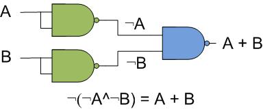
24 Using NOR only (your turn) Can you do it? NOR is (A + B) I.e., We need to write NOT, AND, and OR in terms of NOR NOT = (A + A) = A ^ A = A AND = ( (A + A) + (B + B)) = ( A ^ A + B ^ B) = ( A + B) = ( A) ^ ( B) = A ^ B OR = ( (A + B) + (A + B)) = (A + B) ^ (A + B) = A + B 24
25 Using NOR only (your turn) 25
26 Now, it s really your turn. How about XOR? A B C C = A B + AB 26
27 Now, it s really your turn. How about XOR? A B C C = A B + AB
28 Simplifying expressions Input Output A B C in S C out C out = A BC in + AB C in + ABC in + ABC in C out = BC in + AC in + AB Simplification reduces complexity: faster, smaller circuit! 28
29 Karnaugh map C out = A BC in + AB C in + ABC in + ABC in BC in A 0 1 A tool to help simplify boolean expressions Like a slide rule : Useful but limited A truth table listing minterms Minterms written in Gray code order One var value changes betw. col/row Build from the initial boolean expr. Put a 1 where a minterm is true AC in E.g.., AB C in has a BC in AB Now, to simplify: Look for adjacent max rectangular groups with power of 2 elements. In such a group, some var is {0,1} Eliminate that variable C out = BC in +AB+AC in Here s another one! Groups can be vertical too. They can even wrap around They can also overlap Diagonals aren t allowed 29
30 C out = A BC in + AB C in + ABC in + ABC in S = A B C in + A BC in + AB C in + ABC in BC in A 0 1 BC in A AC in BC in AB C out = BC in +AB+AC in S = A B C in + A BC in + AB C in + ABC in 30
31 Four (or more?) Variables AB AB CD CD Can you minimize this one? In AB: B is both {0,1} In CD: C is both {0,1} Eliminate B, C Thus, we have just AD Can you minimize this one? C,D both have {0,1} A has {0,1} Eliminate A,C,D Thus, we have just B 31
32 Four (or more?) Variables AB CD Can you minimize this one? Combine on top row Combine on bottom row A B D AB D These terms can now combine Thus, we have B D Karnaugh Maps (K-Maps) are a simple calculation tool. In practice, sophisticated logic synthesis algorithms/tools are used. 32

33 In-class Example A device called a 7 segment LED digit There are 8 LEDs one for seven segments of a numeral and 1 for a decimal point Problem Given a 3-bit number, draw the corresponding numeral E.g., 000 is the numeral 0, 001 is numeral 1 and so forth Solution Create a Boolean function for each segment. Ignore the decimal point. Boolean function over three inputs for the 3-bit number. Let s try it!! 33
34 d0 d1 d2 d3 Segments numbered d0 to d7 Hex Digit LED 7 segments, 1 decimal point Turn each segment on/off State: 0=OFF, 1=ON Draw numbers 0 to 9 d7 d6 d5 d4
35 d0 d1 d2 d3 Numeral d0 d7 Hex Digit LED 7 segments, 1 decimal point Turn each segment on/off State: 0=OFF, 1=ON Draw numbers 0 to 9 d7 d6 d5 d4
36 d0 d1 d2 d3 Numeral d0 d7 Hex Digit LED 7 segments, 1 decimal point Turn each segment on/off State: 0=OFF, 1=ON Draw numbers 0 to 9 d7 d6 d5 d4
37 d0 d1 d2 d3 Numeral d0 d7 Hex Digit LED 7 segments, 1 decimal point Turn each segment on/off State: 0=OFF, 1=ON Draw numbers 0 to 9 d7 d6 d5 d4
38 d0 d1 d2 d3 Numeral d0 d7 Hex Digit LED 7 segments, 1 decimal point Turn each segment on/off State: 0=OFF, 1=ON Draw numbers 0 to 9 d7 d6 d5 d4
39 d0 d1 d2 d3 Numeral d0 d7 Hex Digit LED 7 segments, 1 decimal point Turn each segment on/off State: 0=OFF, 1=ON Draw numbers 0 to 9 d7 d6 d5 d4
40 d0 d1 d2 d3 Numeral d0 d7 Hex Digit LED 7 segments, 1 decimal point Turn each segment on/off State: 0=OFF, 1=ON Draw numbers 0 to 9 d7 d6 d5 d4
41 d0 d1 d2 d3 Numeral d0 d7 Hex Digit LED 7 segments, 1 decimal point Turn each segment on/off State: 0=OFF, 1=ON Draw numbers 0 to 9 d7 d6 d5 d4
42 d0 d1 d2 d3 Numeral d0 d7 Hex Digit LED 7 segments, 1 decimal point Turn each segment on/off State: 0=OFF, 1=ON Draw numbers 0 to 9 d7 d6 d5 d4
43 In-class Example Create a truth table Inputs are numbered i0 to i2 (3 bits) Outputs are numbered d0 to d7, corresponding to segments Draw the numerals by setting d0 to d7 to 1s or 0s. 43
44 inputs outputs i2 i1 i0 d0 d1 d2 d3 d4 d5 d6 d Input: 3-bit number Outputs: Segments for the LED hex digit
45 inputs outputs i2 i1 i0 d0 d1 d2 d3 d4 d5 d6 d Fill in the truth table for each numeral Numerals 0 to 2 are shown. Can you complete 3 to 7?
46 inputs outputs i2 i1 i0 d0 d1 d2 d3 d4 d5 d6 d Completed truth table Now, write down the minimal (simplified) Boolean functions Use a K-map to minimize each one!
47 inputs outputs i2 i1 i0 d0 d1 d2 d3 d4 d5 d6 d Completed truth table Now, write down the minimal (simplified) Boolean functions Use a K-map to minimize each one!
48 i1, i i2 0 1 Use a K-map for each output function d0 to d7 Let s start with d0 We ll only do a few d0, d3 and d5 Can you do the rest on your own???
49 Function d0 i1, i i i2 i1 i0 d0 d1 d2 d3 d4 d5 d6 d
50 Function d0 i1, i i i2 i1 i0 d0 d1 d2 d3 d4 d5 d6 d terms i2 i1 i2i1 I2i0 d0=i2i1 + i2i1 + i2i0
51 Function d3 i1, i i i2 i1 i0 d0 d1 d2 d3 d4 d5 d6 d
52 Function d3 i1, i i i2 i1 i0 d0 d1 d2 d3 d4 d5 d6 d d3=i2 + i1i0 + i1i0
53 Function d5 i1, i i i2 i1 i0 d0 d1 d2 d3 d4 d5 d6 d
54 Function d5 i1, i i i2 i1 i0 d0 d1 d2 d3 d4 d5 d6 d d5=i1 + i0 + i2
55 Completed Circuit with all functions d0 to d7 Inputs Outputs to the LED hex digit See example: LEDhexdigit.circ
?")
56 Multiplexor (aka MUX) An example, yet VERY useful circuit! A B 0 1 Y S A B Y 0 0 x x 1 1 x x 1 1 S=1 S=0 Y = (S)? B:A; Y=S A+SB when S = 0: output A 1: output B 56
57 A 32-bit MUX Use 32 1-bit muxes Each mux selects 1 bit S is connected to each mux 57
58 Building a 1-bit ALU ALU = arithmetic logic unit = arithmetic unit + logic unit 58
59 Building a 32-bit ALU 59
60 Implementing sub Binvert=1 CarryIn=1 for 1 st 1-bit ALU Operation=2 60
61 Implementing NAND and NOR NOR: NOT (A OR B) by DeMorgan s Law: (NOT A) AND (NOT B) Thus, Operation=0, Ainvert=1, Binvert=1 And, NAND??? 61
62 Implementing SLT (set-less-than) 1-bit ALU for bits 0~30 1-bit ALU for bit 31 62
63 Implementing SLT (set-less-than) SLT uses subtraction slt $t0,$t1,$t2 $t1<$t2: $t1-$t2 gives negative result set is 1 when negative 1 0 Setting the control perform subtraction (Cin=1,Binvert=1) select Less as output (Operation=3) ALU31 s Set connected to ALU0 Less 0 Consider Suppose $t1=10 and $t2=11 $t1 - $t2 = -1 = binary $t0 =
64 Implementing SLT (set-less-than) SLT uses subtraction slt $t0,$t1,$t2 $t1<$t2: $t1-$t2 gives negative result set is 1 when negative Setting the control perform subtraction (Cin=1,Binvert=1) select Less as output (Operation=3) ALU31 s Set connected to ALU0 Less Why do we need Set? Could we use just the Result31? 64
65 Supporting BEQ and BNE BEQ uses subtraction beq $t0,$t1,label perform $t0-$t1 result=0 è equality zero detector Setting the control subtract (Cin=1,Binvert=1) select result (operation=2) detect zero result 65
66 Abstracting ALU Note that ALU is a combinational logic 66
CS/COE1541: Introduction to Computer Architecture. Logic Design Review. Sangyeun Cho. Computer Science Department University of Pittsburgh
 CS/COE54: Introduction to Computer Architecture Logic Design Review Sangyeun Cho Computer Science Department Logic design? Digital hardware is implemented by way of logic design Digital circuits process
CS/COE0447: Computer Organization
 CS/COE0447: Computer Organization and Assembly Language Logic Design Review Sangyeun Cho Dept. of Computer Science Logic design? Digital hardware is implemented by way of logic design Digital circuits
CS/COE0447: Computer Organization
 Logic design? CS/COE0447: Computer Organization and Assembly Language Logic Design Review Digital hardware is implemented by way of logic design Digital circuits process and produce two discrete values:
Logic design? Transistor as a switch. Layered design approach. CS/COE1541: Introduction to Computer Architecture. Logic Design Review.
 Logic design? CS/COE54: Introduction to Computer rchitecture Digital hardware is implemented by way of logic design Digital circuits process and produce two discrete values: and Example: -bit full adder
Digital Logic. CS211 Computer Architecture. l Topics. l Transistors (Design & Types) l Logic Gates. l Combinational Circuits.
 l Logic Gates. l Combinational Circuits.") CS211 Computer Architecture Digital Logic l Topics l Transistors (Design & Types) l Logic Gates l Combinational Circuits l K-Maps Figures & Tables borrowed from:! http://www.allaboutcircuits.com/vol_4/index.html!
CS211 Computer Architecture Digital Logic l Topics l Transistors (Design & Types) l Logic Gates l Combinational Circuits l K-Maps Figures & Tables borrowed from:! http://www.allaboutcircuits.com/vol_4/index.html!
Digital Logic (2) Boolean Algebra
 Boolean Algebra") Digital Logic (2) Boolean Algebra Boolean algebra is the mathematics of digital systems. It was developed in 1850 s by George Boole. We will use Boolean algebra to minimize logic expressions. Karnaugh
Digital Logic (2) Boolean Algebra Boolean algebra is the mathematics of digital systems. It was developed in 1850 s by George Boole. We will use Boolean algebra to minimize logic expressions. Karnaugh
EE40 Lec 15. Logic Synthesis and Sequential Logic Circuits
 EE40 Lec 15 Logic Synthesis and Sequential Logic Circuits Prof. Nathan Cheung 10/20/2009 Reading: Hambley Chapters 7.4-7.6 Karnaugh Maps: Read following before reading textbook http://www.facstaff.bucknell.edu/mastascu/elessonshtml/logic/logic3.html
Boolean Algebra and Digital Logic 2009, University of Colombo School of Computing
 IT 204 Section 3.0 Boolean Algebra and Digital Logic Boolean Algebra 2 Logic Equations to Truth Tables X = A. B + A. B + AB A B X 0 0 0 0 3 Sum of Products The OR operation performed on the products of
Number System. Decimal to binary Binary to Decimal Binary to octal Binary to hexadecimal Hexadecimal to binary Octal to binary
 Number System Decimal to binary Binary to Decimal Binary to octal Binary to hexadecimal Hexadecimal to binary Octal to binary BOOLEAN ALGEBRA BOOLEAN LOGIC OPERATIONS Logical AND Logical OR Logical COMPLEMENTATION
Chapter 7 Logic Circuits
 Chapter 7 Logic Circuits Goal. Advantages of digital technology compared to analog technology. 2. Terminology of Digital Circuits. 3. Convert Numbers between Decimal, Binary and Other forms. 5. Binary
ECE/CS 250 Computer Architecture
 ECE/CS 250 Computer Architecture Basics of Logic Design: Boolean Algebra, Logic Gates (Combinational Logic) Tyler Bletsch Duke University Slides are derived from work by Daniel J. Sorin (Duke), Alvy Lebeck
EEE130 Digital Electronics I Lecture #4
 EEE130 Digital Electronics I Lecture #4 - Boolean Algebra and Logic Simplification - By Dr. Shahrel A. Suandi Topics to be discussed 4-1 Boolean Operations and Expressions 4-2 Laws and Rules of Boolean
ECE 250 / CPS 250 Computer Architecture. Basics of Logic Design Boolean Algebra, Logic Gates
 ECE 250 / CPS 250 Computer Architecture Basics of Logic Design Boolean Algebra, Logic Gates Benjamin Lee Slides based on those from Andrew Hilton (Duke), Alvy Lebeck (Duke) Benjamin Lee (Duke), and Amir
Logic Design. Chapter 2: Introduction to Logic Circuits
 Logic Design Chapter 2: Introduction to Logic Circuits Introduction Logic circuits perform operation on digital signal Digital signal: signal values are restricted to a few discrete values Binary logic
EECS150 - Digital Design Lecture 19 - Combinational Logic Circuits : A Deep Dive
 EECS150 - Digital Design Lecture 19 - Combinational Logic Circuits : A Deep Dive March 30, 2010 John Wawrzynek Spring 2010 EECS150 - Lec19-cl1 Page 1 Boolean Algebra I (Representations of Combinational
Lecture 22 Chapters 3 Logic Circuits Part 1
 Lecture 22 Chapters 3 Logic Circuits Part 1 LC-3 Data Path Revisited How are the components Seen here implemented? 5-2 Computing Layers Problems Algorithms Language Instruction Set Architecture Microarchitecture
Why digital? Overview. Number Systems. Binary to Decimal conversion
 Why digital? Overview It has the following advantages over analog. It can be processed and transmitted efficiently and reliably. It can be stored and retrieved with greater accuracy. Noise level does not
ECE/CS 250: Computer Architecture. Basics of Logic Design: Boolean Algebra, Logic Gates. Benjamin Lee
 ECE/CS 250: Computer Architecture Basics of Logic Design: Boolean Algebra, Logic Gates Benjamin Lee Slides based on those from Alvin Lebeck, Daniel Sorin, Andrew Hilton, Amir Roth, Gershon Kedem Admin
CHAPTER1: Digital Logic Circuits Combination Circuits
 CS224: Computer Organization S.KHABET CHAPTER1: Digital Logic Circuits Combination Circuits 1 PRIMITIVE LOGIC GATES Each of our basic operations can be implemented in hardware using a primitive logic gate.
Digital Logic Appendix A
 Digital Logic Appendix A Boolean Algebra Gates Combinatorial Circuits Sequential Circuits 1 Boolean Algebra George Boole ideas 1854 Claude Shannon, apply to circuit design, 1938 Describe digital circuitry
COSC 243. Introduction to Logic And Combinatorial Logic. Lecture 4 - Introduction to Logic and Combinatorial Logic. COSC 243 (Computer Architecture)
") COSC 243 Introduction to Logic And Combinatorial Logic 1 Overview This Lecture Introduction to Digital Logic Gates Boolean algebra Combinatorial Logic Source: Chapter 11 (10 th edition) Source: J.R. Gregg,
COSC 243 Introduction to Logic And Combinatorial Logic 1 Overview This Lecture Introduction to Digital Logic Gates Boolean algebra Combinatorial Logic Source: Chapter 11 (10 th edition) Source: J.R. Gregg,
Introduction to Karnaugh Maps
 Introduction to Karnaugh Maps Review So far, you (the students) have been introduced to truth tables, and how to derive a Boolean circuit from them. We will do an example. Consider the truth table for
Combinational Logic. Review of Combinational Logic 1
 Combinational Logic! Switches -> Boolean algebra! Representation of Boolean functions! Logic circuit elements - logic gates! Regular logic structures! Timing behavior of combinational logic! HDLs and combinational
CSC9R6 Computer Design. Practical Digital Logic
 CSC9R6 Computer Design Practical Digital Logic 1 References (for this part of CSC9R6) Hamacher et al: Computer Organization App A. In library Floyd: Digital Fundamentals Ch 1, 3-6, 8-10 web page: www.prenhall.com/floyd/
Fundamentals of Digital Design
 Fundamentals of Digital Design Digital Radiation Measurement and Spectroscopy NE/RHP 537 1 Binary Number System The binary numeral system, or base-2 number system, is a numeral system that represents numeric
ENG2410 Digital Design Combinational Logic Circuits
 ENG240 Digital Design Combinational Logic Circuits Fall 207 S. Areibi School of Engineering University of Guelph Binary variables Binary Logic Can be 0 or (T or F, low or high) Variables named with single
Boolean Algebra & Logic Gates. By : Ali Mustafa
 Boolean Algebra & Logic Gates By : Ali Mustafa Digital Logic Gates There are three fundamental logical operations, from which all other functions, no matter how complex, can be derived. These Basic functions
EECS150 - Digital Design Lecture 4 - Boolean Algebra I (Representations of Combinational Logic Circuits)
") EECS150 - Digital Design Lecture 4 - Boolean Algebra I (Representations of Combinational Logic Circuits) September 5, 2002 John Wawrzynek Fall 2002 EECS150 Lec4-bool1 Page 1, 9/5 9am Outline Review of
EECS150 - Digital Design Lecture 4 - Boolean Algebra I (Representations of Combinational Logic Circuits) September 5, 2002 John Wawrzynek Fall 2002 EECS150 Lec4-bool1 Page 1, 9/5 9am Outline Review of
Number System conversions
 Number System conversions Number Systems The system used to count discrete units is called number system. There are four systems of arithmetic which are often used in digital electronics. Decimal Number
Outline. EECS150 - Digital Design Lecture 4 - Boolean Algebra I (Representations of Combinational Logic Circuits) Combinational Logic (CL) Defined
 Combinational Logic (CL) Defined") EECS150 - Digital Design Lecture 4 - Boolean Algebra I (Representations of Combinational Logic Circuits) January 30, 2003 John Wawrzynek Outline Review of three representations for combinational logic:
EECS150 - Digital Design Lecture 4 - Boolean Algebra I (Representations of Combinational Logic Circuits) January 30, 2003 John Wawrzynek Outline Review of three representations for combinational logic:
MC9211 Computer Organization
 MC92 Computer Organization Unit : Digital Fundamentals Lesson2 : Boolean Algebra and Simplification (KSB) (MCA) (29-2/ODD) (29 - / A&B) Coverage Lesson2 Introduces the basic postulates of Boolean Algebra
Boolean Algebra. Digital Logic Appendix A. Postulates, Identities in Boolean Algebra How can I manipulate expressions?
 Digital Logic Appendix A Gates Combinatorial Circuits Sequential Circuits Other operations NAND A NAND B = NOT ( A ANDB) = AB NOR A NOR B = NOT ( A ORB) = A + B Truth tables What is the result of the operation
UNIVERSITI TENAGA NASIONAL. College of Information Technology
 UNIVERSITI TENAGA NASIONAL College of Information Technology BACHELOR OF COMPUTER SCIENCE (HONS.) FINAL EXAMINATION SEMESTER 2 2012/2013 DIGITAL SYSTEMS DESIGN (CSNB163) January 2013 Time allowed: 3 hours
4 Switching Algebra 4.1 Axioms; Signals and Switching Algebra
 4 Switching Algebra 4.1 Axioms; Signals and Switching Algebra To design a digital circuit that will perform a required function, it is necessary to manipulate and combine the various input signals in certain
XI STANDARD [ COMPUTER SCIENCE ] 5 MARKS STUDY MATERIAL.
![XI STANDARD [ COMPUTER SCIENCE ] 5 MARKS STUDY MATERIAL.](/thumbs/81/84726747.jpg "XI STANDARD [ COMPUTER SCIENCE ] 5 MARKS STUDY MATERIAL.") 2017-18 XI STANDARD [ COMPUTER SCIENCE ] 5 MARKS STUDY MATERIAL HALF ADDER 1. The circuit that performs addition within the Arithmetic and Logic Unit of the CPU are called adders. 2. A unit that adds two
2017-18 XI STANDARD [ COMPUTER SCIENCE ] 5 MARKS STUDY MATERIAL HALF ADDER 1. The circuit that performs addition within the Arithmetic and Logic Unit of the CPU are called adders. 2. A unit that adds two
Review for Test 1 : Ch1 5
 Review for Test 1 : Ch1 5 October 5, 2006 Typeset by FoilTEX Positional Numbers 527.46 10 = (5 10 2 )+(2 10 1 )+(7 10 0 )+(4 10 1 )+(6 10 2 ) 527.46 8 = (5 8 2 ) + (2 8 1 ) + (7 8 0 ) + (4 8 1 ) + (6 8
ENGG 1203 Tutorial - 2 Recall Lab 2 - e.g. 4 input XOR. Parity checking (for interest) Recall : Simplification methods. Recall : Time Delay
 Recall : Simplification methods. Recall : Time Delay") ENGG 23 Tutorial - 2 Recall Lab 2 - e.g. 4 input XOR Parity checking (for interest) Parity bit Parity checking Error detection, eg. Data can be Corrupted Even parity total number of s is even Odd parity
ENGG 23 Tutorial - 2 Recall Lab 2 - e.g. 4 input XOR Parity checking (for interest) Parity bit Parity checking Error detection, eg. Data can be Corrupted Even parity total number of s is even Odd parity
Chapter 2 Combinational logic
 Chapter 2 Combinational logic Chapter 2 is very easy. I presume you already took discrete mathemtics. The major part of chapter 2 is boolean algebra. II - Combinational Logic Copyright 24, Gaetano Borriello
Boolean algebra. Examples of these individual laws of Boolean, rules and theorems for Boolean algebra are given in the following table.
 The Laws of Boolean Boolean algebra As well as the logic symbols 0 and 1 being used to represent a digital input or output, we can also use them as constants for a permanently Open or Closed circuit or
Hakim Weatherspoon CS 3410 Computer Science Cornell University
 Hakim Weatherspoon CS 3410 Computer Science Cornell University The slides are the product of many rounds of teaching CS 3410 by Professors Weatherspoon, Bala, Bracy, and Sirer. memory inst 32 register
CS 226: Digital Logic Design
 CS 226: Digital Logic Design 0 1 1 I S 0 1 0 S Department of Computer Science and Engineering, Indian Institute of Technology Bombay. 1 of 29 Objectives In this lecture we will introduce: 1. Logic functions
Switches: basic element of physical implementations
 Combinational logic Switches Basic logic and truth tables Logic functions Boolean algebra Proofs by re-writing and by perfect induction Winter 200 CSE370 - II - Boolean Algebra Switches: basic element
Week-I. Combinational Logic & Circuits
 Week-I Combinational Logic & Circuits Overview Binary logic operations and gates Switching algebra Algebraic Minimization Standard forms Karnaugh Map Minimization Other logic operators IC families and
Philadelphia University Student Name: Student Number:
 Philadelphia University Student Name: Student Number: Faculty of Engineering Serial Number: Final Exam, First Semester: 2017/2018 Dept. of Computer Engineering Course Title: Logic Circuits Date: 29/01/2018
COS 140: Foundations of Computer Science
 COS 140: Foundations of Computer Science Boolean Algebra Fall 2018 Introduction 3 Problem................................................................. 3 Boolean algebra...........................................................
Propositional Logic. Logical Expressions. Logic Minimization. CNF and DNF. Algebraic Laws for Logical Expressions CSC 173
 Propositional Logic CSC 17 Propositional logic mathematical model (or algebra) for reasoning about the truth of logical expressions (propositions) Logical expressions propositional variables or logical
S C F F F T T F T T S C B F F F F F T F T F F T T T F F T F T T T F T T T
 EECS 270, Winter 2017, Lecture 1 Page 1 of 6 Use pencil! Say we live in the rather black and white world where things (variables) are either true (T) or false (F). So if S is Mark is going to the Store
Gates and Logic: From switches to Transistors, Logic Gates and Logic Circuits
 Gates and Logic: From switches to Transistors, Logic Gates and Logic Circuits Hakim Weatherspoon CS 3410, Spring 2013 Computer Science Cornell University See: P&H ppendix C.2 and C.3 (lso, see C.0 and
211: Computer Architecture Summer 2016
 211: Computer Architecture Summer 2016 Liu Liu Topic: Storage Project3 Digital Logic - Storage: Recap - Review: cache hit rate - Project3 - Digital Logic: - truth table => SOP - simplification: Boolean
Ch 2. Combinational Logic. II - Combinational Logic Contemporary Logic Design 1
 Ch 2. Combinational Logic II - Combinational Logic Contemporary Logic Design 1 Combinational logic Define The kind of digital system whose output behavior depends only on the current inputs memoryless:
Possible logic functions of two variables
 ombinational logic asic logic oolean algebra, proofs by re-writing, proofs by perfect induction logic functions, truth tables, and switches NOT, ND, OR, NND, NOR, OR,..., minimal set Logic realization
Logic Simplification. Boolean Simplification Example. Applying Boolean Identities F = A B C + A B C + A BC + ABC. Karnaugh Maps 2/10/2009 COMP370 1
 Digital Logic COMP370 Introduction to Computer Architecture Logic Simplification It is frequently possible to simplify a logical expression. This makes it easier to understand and requires fewer gates
Digital Logic: Boolean Algebra and Gates. Textbook Chapter 3
 Digital Logic: Boolean Algebra and Gates Textbook Chapter 3 Basic Logic Gates XOR CMPE12 Summer 2009 02-2 Truth Table The most basic representation of a logic function Lists the output for all possible
Sample Test Paper - I
 Scheme G Sample Test Paper - I Course Name : Computer Engineering Group Marks : 25 Hours: 1 Hrs. Q.1) Attempt any THREE: 09 Marks a) Define i) Propagation delay ii) Fan-in iii) Fan-out b) Convert the following:
Logic and Boolean algebra
 Computer Mathematics Week 7 Logic and Boolean algebra College of Information Science and Engineering Ritsumeikan University last week coding theory channel coding information theory concept Hamming distance
Systems I: Computer Organization and Architecture
 Systems I: Computer Organization and Architecture Lecture 6 - Combinational Logic Introduction A combinational circuit consists of input variables, logic gates, and output variables. The logic gates accept
UNIT 4 MINTERM AND MAXTERM EXPANSIONS
 UNIT 4 MINTERM AND MAXTERM EXPANSIONS Spring 2 Minterm and Maxterm Expansions 2 Contents Conversion of English sentences to Boolean equations Combinational logic design using a truth table Minterm and
BOOLEAN ALGEBRA. Introduction. 1854: Logical algebra was published by George Boole known today as Boolean Algebra
 BOOLEAN ALGEBRA Introduction 1854: Logical algebra was published by George Boole known today as Boolean Algebra It s a convenient way and systematic way of expressing and analyzing the operation of logic
Chap 2. Combinational Logic Circuits
 Overview 2 Chap 2. Combinational Logic Circuits Spring 24 Part Gate Circuits and Boolean Equations Binary Logic and Gates Boolean Algebra Standard Forms Part 2 Circuit Optimization Two-Level Optimization
Combinational Logic. By : Ali Mustafa
 Combinational Logic By : Ali Mustafa Contents Adder Subtractor Multiplier Comparator Decoder Encoder Multiplexer How to Analyze any combinational circuit like this? Analysis Procedure To obtain the output
Slide Set 3. for ENEL 353 Fall Steve Norman, PhD, PEng. Electrical & Computer Engineering Schulich School of Engineering University of Calgary
 Slide Set 3 for ENEL 353 Fall 2016 Steve Norman, PhD, PEng Electrical & Computer Engineering Schulich School of Engineering University of Calgary Fall Term, 2016 SN s ENEL 353 Fall 2016 Slide Set 3 slide
ECE 545 Digital System Design with VHDL Lecture 1. Digital Logic Refresher Part A Combinational Logic Building Blocks
 ECE 545 Digital System Design with VHDL Lecture Digital Logic Refresher Part A Combinational Logic Building Blocks Lecture Roadmap Combinational Logic Basic Logic Review Basic Gates De Morgan s Law Combinational
Prove that if not fat and not triangle necessarily means not green then green must be fat or triangle (or both).
.") hapter : oolean lgebra.) Definition of oolean lgebra The oolean algebra is named after George ool who developed this algebra (854) in order to analyze logical problems. n example to such problem is: Prove
hapter : oolean lgebra.) Definition of oolean lgebra The oolean algebra is named after George ool who developed this algebra (854) in order to analyze logical problems. n example to such problem is: Prove
Simplifying Logic Circuits with Karnaugh Maps
 Simplifying Logic Circuits with Karnaugh Maps The circuit at the top right is the logic equivalent of the Boolean expression: f = abc + abc + abc Now, as we have seen, this expression can be simplified
2. Associative Law: A binary operator * on a set S is said to be associated whenever (A*B)*C = A*(B*C) for all A,B,C S.
*C = A*(B*C) for all A,B,C S.") BOOLEAN ALGEBRA 2.1 Introduction Binary logic deals with variables that have two discrete values: 1 for TRUE and 0 for FALSE. A simple switching circuit containing active elements such as a diode and transistor
BOOLEAN ALGEBRA 2.1 Introduction Binary logic deals with variables that have two discrete values: 1 for TRUE and 0 for FALSE. A simple switching circuit containing active elements such as a diode and transistor
Boolean Algebra and logic gates
 Boolean Algebra and logic gates Luis Entrena, Celia López, Mario García, Enrique San Millán Universidad Carlos III de Madrid 1 Outline l Postulates and fundamental properties of Boolean Algebra l Boolean
Review. EECS Components and Design Techniques for Digital Systems. Lec 06 Minimizing Boolean Logic 9/ Review: Canonical Forms
 Review EECS 150 - Components and Design Techniques for Digital Systems Lec 06 Minimizing Boolean Logic 9/16-04 David Culler Electrical Engineering and Computer Sciences University of California, Berkeley
ELCT201: DIGITAL LOGIC DESIGN
 ELCT2: DIGITAL LOGIC DESIGN Dr. Eng. Haitham Omran, haitham.omran@guc.edu.eg Dr. Eng. Wassim Alexan, wassim.joseph@guc.edu.eg Lecture 2 Following the slides of Dr. Ahmed H. Madian ذو الحجة 438 ه Winter
Floating Point Representation and Digital Logic. Lecture 11 CS301
 Floating Point Representation and Digital Logic Lecture 11 CS301 Administrative Daily Review of today s lecture w Due tomorrow (10/4) at 8am Lab #3 due Friday (9/7) 1:29pm HW #5 assigned w Due Monday 10/8
Logic Gate Level. Part 2
 Logic Gate Level Part 2 Constructing Boolean expression from First method: write nonparenthesized OR of ANDs Each AND is a 1 in the result column of the truth table Works best for table with relatively
 vidyarthiplus.com vidyarthiplus.com vidyarthiplus.com ANNA UNIVERSITY- COMBATORE B.E./ B.TECH. DEGREE EXAMINATION - JUNE 2009. ELECTRICAL & ELECTONICS ENGG. - FOURTH SEMESTER DIGITAL LOGIC CIRCUITS PART-A
Contents. Chapter 3 Combinational Circuits Page 1 of 36
 Chapter 3 Combinational Circuits Page of 36 Contents Combinational Circuits...2 3. Analysis of Combinational Circuits...3 3.. Using a Truth Table...3 3..2 Using a Boolean Function...6 3.2 Synthesis of
Boolean Algebra. Digital Logic Appendix A. Boolean Algebra Other operations. Boolean Algebra. Postulates, Identities in Boolean Algebra
 Digital Logic Appendix A Gates Combinatorial Circuits Sequential Circuits George Boole ideas 1854 Claude Shannon, apply to circuit design, 1938 (piirisuunnittelu) Describe digital circuitry function programming
Boolean Algebra, Gates and Circuits
 Boolean Algebra, Gates and Circuits Kasper Brink November 21, 2017 (Images taken from Tanenbaum, Structured Computer Organization, Fifth Edition, (c) 2006 Pearson Education, Inc.) Outline Last week: Von
T02 Tutorial Slides for Week 6
 T02 Tutorial Slides for Week 6 ENEL 353: Digital Circuits Fall 2017 Term Steve Norman, PhD, PEng Electrical & Computer Engineering Schulich School of Engineering University of Calgary 17 October, 2017
Combinational logic. Possible logic functions of two variables. Minimal set of functions. Cost of different logic functions.
 Combinational logic Possible logic functions of two variables Logic functions, truth tables, and switches NOT, ND, OR, NND, NOR, OR,... Minimal set xioms and theorems of oolean algebra Proofs by re-writing
Chapter 4. Combinational: Circuits with logic gates whose outputs depend on the present combination of the inputs. elements. Dr.
 Chapter 4 Dr. Panos Nasiopoulos Combinational: Circuits with logic gates whose outputs depend on the present combination of the inputs. Sequential: In addition, they include storage elements Combinational
EECS Variable Logic Functions
 EECS150 Section 1 Introduction to Combinational Logic Fall 2001 2-Variable Logic Functions There are 16 possible functions of 2 input variables: in general, there are 2**(2**n) functions of n inputs X
Lecture 2 Review on Digital Logic (Part 1)
") Lecture 2 Review on Digital Logic (Part 1) Xuan Silvia Zhang Washington University in St. Louis http://classes.engineering.wustl.edu/ese461/ Grading Engagement 5% Review Quiz 10% Homework 10% Labs 40%
Lecture 2 Review on Digital Logic (Part 1) Xuan Silvia Zhang Washington University in St. Louis http://classes.engineering.wustl.edu/ese461/ Grading Engagement 5% Review Quiz 10% Homework 10% Labs 40%
Combinatorial Logic Design Principles
 Combinatorial Logic Design Principles ECGR2181 Chapter 4 Notes Logic System Design I 4-1 Boolean algebra a.k.a. switching algebra deals with boolean values -- 0, 1 Positive-logic convention analog voltages
Chapter 2: Switching Algebra and Logic Circuits
 Chapter 2: Switching Algebra and Logic Circuits Formal Foundation of Digital Design In 1854 George Boole published An investigation into the Laws of Thoughts Algebraic system with two values 0 and 1 Used
Unit 8A Computer Organization. Boolean Logic and Gates
 Unit 8A Computer Organization Boolean Logic and Gates Announcements Bring ear buds or headphones to lab! 15110 Principles of Computing, Carnegie Mellon University - CORTINA 2 Representing and Manipulating
10/14/2009. Reading: Hambley Chapters
 EE40 Lec 14 Digital Signal and Boolean Algebra Prof. Nathan Cheung 10/14/2009 Reading: Hambley Chapters 7.1-7.4 7.4 Slide 1 Analog Signals Analog: signal amplitude is continuous with time. Amplitude Modulated
Principles of Computer Architecture. Appendix B: Reduction of Digital Logic. Chapter Contents
 B-1 Principles of Computer Architecture Miles Murdocca and Vincent Heuring Appendix B: Reduction of Digital Logic B-2 Chapter Contents B.1 Reduction of Combinational Logic and Sequential Logic B.2 Reduction
CS61c: Representations of Combinational Logic Circuits
 CS61c: Representations of Combinational Logic Circuits J. Wawrzynek March 5, 2003 1 Introduction Recall that synchronous systems are composed of two basic types of circuits, combination logic circuits,
Appendix B. Review of Digital Logic. Baback Izadi Division of Engineering Programs
 Appendix B Review of Digital Logic Baback Izadi Division of Engineering Programs bai@engr.newpaltz.edu Elect. & Comp. Eng. 2 DeMorgan Symbols NAND (A.B) = A +B NOR (A+B) = A.B AND A.B = A.B = (A +B ) OR
Binary Logic and Gates. Our objective is to learn how to design digital circuits.
 Binary Logic and Gates Introduction Our objective is to learn how to design digital circuits. These circuits use binary systems. Signals in such binary systems may represent only one of 2 possible values
Vidyalankar S.E. Sem. III [CMPN] Digital Logic Design and Analysis Prelim Question Paper Solution
![Vidyalankar S.E. Sem. III [CMPN] Digital Logic Design and Analysis Prelim Question Paper Solution](/thumbs/90/103673562.jpg "Vidyalankar S.E. Sem. III [CMPN] Digital Logic Design and Analysis Prelim Question Paper Solution") . (a) (i) ( B C 5) H (A 2 B D) H S.E. Sem. III [CMPN] Digital Logic Design and Analysis Prelim Question Paper Solution ( B C 5) H (A 2 B D) H = (FFFF 698) H (ii) (2.3) 4 + (22.3) 4 2 2. 3 2. 3 2 3. 2 (2.3)
. (a) (i) ( B C 5) H (A 2 B D) H S.E. Sem. III [CMPN] Digital Logic Design and Analysis Prelim Question Paper Solution ( B C 5) H (A 2 B D) H = (FFFF 698) H (ii) (2.3) 4 + (22.3) 4 2 2. 3 2. 3 2 3. 2 (2.3)
Chapter 2 Combinational Logic Circuits
 Logic and Computer Design Fundamentals Chapter 2 Combinational Logic Circuits Part 1 Gate Circuits and Boolean Equations Chapter 2 - Part 1 2 Chapter 2 - Part 1 3 Chapter 2 - Part 1 4 Chapter 2 - Part
Computer Science 324 Computer Architecture Mount Holyoke College Fall Topic Notes: Digital Logic
 Computer Science 324 Computer Architecture Mount Holyoke College Fall 2007 Topic Notes: Digital Logic Our goal for the next few weeks is to paint a a reasonably complete picture of how we can go from transistor
II. COMBINATIONAL LOGIC DESIGN. - algebra defined on a set of 2 elements, {0, 1}, with binary operators multiply (AND), add (OR), and invert (NOT):
, add (OR), and invert (NOT):") ENGI 386 Digital Logic II. COMBINATIONAL LOGIC DESIGN Combinational Logic output of digital system is only dependent on current inputs (i.e., no memory) (a) Boolean Algebra - developed by George Boole
ENGI 386 Digital Logic II. COMBINATIONAL LOGIC DESIGN Combinational Logic output of digital system is only dependent on current inputs (i.e., no memory) (a) Boolean Algebra - developed by George Boole
Every time has a value associated with it, not just some times. A variable can take on any value within a range
 Digital Logic Circuits Binary Logic and Gates Logic Simulation Boolean Algebra NAND/NOR and XOR gates Decoder fundamentals Half Adder, Full Adder, Ripple Carry Adder Analog vs Digital Analog Continuous»
Ex: Boolean expression for majority function F = A'BC + AB'C + ABC ' + ABC.
 Boolean Expression Forms: Sum-of-products (SOP) Write an AND term for each input combination that produces a 1 output. Write the input variable if its value is 1; write its complement otherwise. OR the
This form sometimes used in logic circuit, example:
 Objectives: 1. Deriving of logical expression form truth tables. 2. Logical expression simplification methods: a. Algebraic manipulation. b. Karnaugh map (k-map). 1. Deriving of logical expression from
Numbers & Arithmetic. Hakim Weatherspoon CS 3410, Spring 2012 Computer Science Cornell University. See: P&H Chapter , 3.2, C.5 C.
 Numbers & Arithmetic Hakim Weatherspoon CS 3410, Spring 2012 Computer Science Cornell University See: P&H Chapter 2.4-2.6, 3.2, C.5 C.6 Example: Big Picture Computer System Organization and Programming
UC Berkeley College of Engineering, EECS Department CS61C: Representations of Combinational Logic Circuits
 2 Wawrzynek, Garcia 2004 c UCB UC Berkeley College of Engineering, EECS Department CS61C: Representations of Combinational Logic Circuits 1 Introduction Original document by J. Wawrzynek (2003-11-15) Revised
Unit 2 Session - 6 Combinational Logic Circuits
 Objectives Unit 2 Session - 6 Combinational Logic Circuits Draw 3- variable and 4- variable Karnaugh maps and use them to simplify Boolean expressions Understand don t Care Conditions Use the Product-of-Sums
COMP2611: Computer Organization. Introduction to Digital Logic
 1 OMP2611: omputer Organization ombinational Logic OMP2611 Fall 2015 asics of Logic ircuits 2 its are the basis for binary number representation in digital computers ombining bits into patterns following
Digital Techniques. Figure 1: Block diagram of digital computer. Processor or Arithmetic logic unit ALU. Control Unit. Storage or memory unit
 Digital Techniques 1. Binary System The digital computer is the best example of a digital system. A main characteristic of digital system is its ability to manipulate discrete elements of information.
Review Getting the truth table
 Digital Circuits Review Getting the truth table The first step in designing a digital circuit usually is to get the truth table. That is, for every input combination, figure out what an output bit should