Principles of Finite Element for Design Engineers and Analysts. Ayman Shama, Ph.D., P.E., F.ASCE
|
|
|
- Milton Lester Robinson
- 5 years ago
- Views:
Transcription
1 Principles of Finite Element for Design Engineers and Analysts Ayman Shama, Ph.D., P.E., F.ASCE
2 Outline Principles of Engineering Analysis The development of the finite element method Types of elements Types of analyses Applications of the method in: failure investigations Construction Design
3 Basic Principles of Engineering Analysis Analysis of an Engineering system Formulation of mathematical model Lumped-parameter (discrete systems) Response is described by solution of a set of algebraic equations Continuum-mechanics (continuous systems) Response is described by Solution of a set of differential equations Matrix stiffness method Finite element method
4 The Predecessor of the Finite Element Method The matrix stiffness method was first developed by Collar and Duncan between 1934 and 1938 Further contributions by John Argyris between 1952 and 1958 Limited to one dimensional elements only Deals with discrete mathematical models
5 Overview of the Matrix Stiffness Method A structure consists of one dimensional line elements each has two nodes
6 We define the stiffness as the force applied at a certain node to produce a unit deformation at this node or at another node. Therefore: P = the applied force P K K= the stiffness = the displacement For a two node member with only one degree of freedom P 1 K11 1 K12 2 P K K P P 1 2 K K K K
7 Step 1: Determine the stiffness matrices of all elements EA/L EI z L EI z L 2 K 11 12EI 0 0 y 6EI L 3 0 y L GJ/L EI y L 2 0 4EI y /L 0 0 6EI z L EI z /L EA/L EI z L EI z L 2 K 12 12EI 0 0 y 6EI L 3 0 y L GJ/L EI y L 2 0 2EI y /L 0 0 6EI z L EI z /L
8 Step 2: Build up the overall structure stiffness matrix for the whole structure Step 3: Solve for the nodal displacements K 11 K 12 K K 21 K 22 K K 31 K 32 K 33 K 34 K K 43 K 44 K K 53 K 54 K 55 K K 65 K 66 Step 4: Knowing nodal displacements, determine internal forces in each member and reactions
9 The Boeing Project Collaboration between Berkley and Boeing One-dimensional elements failed to model the experimental behavior of wing structures Jon Turner proposed 2-dimensional elements Ray Clough provided analysis and calculations The study resulted in a formulation of the constant strain triangular membrane element
10 The Birth of the Finite Element Method Clough coined the terminology finite element method in his paper Presented a FE approach of two-dimensional elements to solve problems in continuum mechanics
11 How Finite Element Method Works? Step 1: The continuum is idealized as an assemblage of a number of discrete elements connected at the nodes only
12 Step 2: Assume a displacement field: Polynomials used to specify the relationship between the internal displacements of each element and its nodal displacements The displacement field is used as a basis for the element stiffness matrix Example (triangular element): u x, y v x, y = a 0 + a 1 x + a 2 y = b 0 + b 1 x + b 2 y Constant stress element Provides stresses, strains, and displacements at one point inside the element
13 Displacements: In matrix form Apply at nodes u x, y v x, y u i n v i n u j n v j n u k n v k n u v = a 0 + a 1 x + a 2 y = b 0 + b 1 x + b 2 y = 1 x y x y = φ { } = 1 x i y i x i y i 1 x j y j x j y j 1 x k y k x k y k a 0 a 1 a 2 b 0 b 1 b 2 a 0 a 1 a 2 b 0 b 1 b 2 n = A { } = A 1 { n } or Therefore = φ A 1 { n } or = N { n } N
14 Strain: From theory of elasticity strain is evaluated ε = ε = Stain displacement transformation matrix ε x ε y γ xy = u x v y u y + v x 1 x i y i x j y i 1 x j y j x j y j 1 x k y k x k y k {ε} = B {Δ n } 1 u i n v i n u j n v j n u k n v k n
15 Stress: In isotropic material of Young s modulus E and Poisson s ν ratio stresses and strains are related by σ x σ y = E 1 υ 0 σ 1 v υ ε x 0 x E υ 1 0 σ υ τ xy 1 υ υ vε y 0 y = τ γ xy xy (1 + v)(1 2v) 1 2υ {σ} = D {ε} The stiffness matrix of the plate element is obtained using the principle of virtual displacements The virtual work done by the external forces is equal to the virtual work done by internal stresses P = ε x ε y γ xy x P i P i y P j x P j y P k x P k y


16 Evaluate element stiffness matrix: The virtual work done by nodal external forces W e = { n v } T {P} The virtual work done by internal stresses Therefore Element stiffness matrix
17 Step 3: Build up the overall structure stiffness matrix for the whole assemblage Step 4: Solve for the nodal displacements Step 5: {Δ n } = K 1 P Knowing nodal displacements, determine internal displacements, strains, and stresses in each element = [N] { n } {ε} = B {Δ n } {σ} = D {ε} [N]= φ A 1
18 urther Developments of the Finite Element Method The Isoparametric element formulation (B. Irons 1966) X = r X r X 2 X = h i X i 2 i=1 2 U = h i U i i=1 The formulation is achieved through the use of shape functions (interpolation functions) and natural coordinate system for the element
19 Shape functions of four to nine nodes two dimensional elements n n X = h i X i Y = h i Y i Coordinate interpolations i=1 i=1 n n U = h i U i V = h i V i i=1 i=1 Element displacements
20 Advantages of isoparametric elements provides the relationship between the element displacement at any point inside the element and the element nodal points displacements No need to evaluate the transformation matrix A -1 Matrix [N] is obtained directly in terms of the shape functions The elements can have curved boundaries
21 Further Developments in the Formulation of Finite Element Equations Melosh (1963) showed that the finite element formulation can be expressed using variational and energy methods using the principle of the minimum potential Barna and Lee (1969) showed that finite element nodal equations can be derived and solved numerically using Galerkin s method. Zienkiewiczs (1971) applied the energy and Galerkin methods to a class of physical problems including structural mechanics, heat transfer, and fluid mechanics. These methods are very powerful for major physical problems that can be idealized in the form of differential equations
22 Types of Elements Used in Finite Element Analysis Truss Element The truss element is usually a 2- node element Subjected to axial loads either tension or compression One degree of freedom, axial displacement Beam Element 2-node element with 6 degrees of freedom Comes with moment release and rigid-end capabilities
23 Two-Dimensional Solid Elements Also called plane element Two translational in plan degrees of freedom at each node, i.e., no rotations or moments Two options either plane stress elements or plane strain elements Plane stress element: Thin plates that are free to move in the direction normal to the plane of the plate Plane strain element: A slice of a very long solid structure such as dams, and retaining walls
24 Axisymmetric Elements Used to model cylindrical structures Both the structure and loading are axisymmetric Provides for the stiffness of one radian of the structure
25 Three-Dimensional Solid Elements Three translational degrees of freedom at each node. i.e. no rotations
26 Shell Elements Carry plate bending, shear and membrane loadings Forces per unit length or stresses can be reported on mid-surface Care has to be taken in selecting the element to avoid locking Plate Elements Special case of shell elements
27 Spring Elements It is used to connect two nodes or to attach a node to ground Forces are calculated in terms of the spring s stiffness and the relative deformation between the element end nodes A damper element provides the same purpose but the relationship is between relative velocities and damping
28 Types of Analyses Linear static analysis Solution of K =P Nonlinear static analysis The analysis is undertaken incrementally in time steps At each step equilibrium satisfies K (t+δt) (i 1) ΔU (i) = P (t+δt) F (t+δt) (i 1) U (t+δt) (i) = U (t+δt) (i 1) + ΔU (i) Dynamic analysis-time domain Linear on nonlinear Newmark method or Wilson method
29 Types of Analyses Dynamic analysis-frequency domain Fourier methods Spectral analysis method (probabilistic) Response spectrum methods Heat transfer analysis Temperature displacement Conductivity modulus of elasticity Heat flux stress or pressure Computational fluid dynamics analysis Principles of conservation of mass, momentum, and energy govern
30 Applications in Failure Investigations
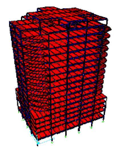
31 Investigation of the Failure of Welded Steel Moment Frame Connections During Northridge Earthquake Inspection of several buildings after the Northridge Earthquake demonstrated damage of the connection. damage occurred in or near the welded joint of the girder bottom flange to the supporting column flange The connection has undergone considerable research under SAC program. A damaged building was subject of this investigation
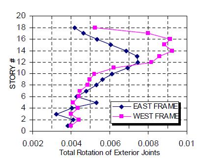
32 Building Subject Investigation A comprehensive survey of the building showed that it was leaning 6 to the north at roof level
33 Building Subject Investigation Inspection of moment frame connections indicated fracture damage at 29 locations in the east and west frames.


34 FE Model of the Connection Stress A36 Beam A572 Grade 50 Column 10 E70 Weld Strain
35 Connection Damage Assessment Triaxiality: T=s H /s eff Hydrostatic stress: s H = (s 1 + s 2 + s 3 )/3 von Mises (effective) stress: (stress)/(yield stress) s y s max triaxial stress state (T=1.5) uniaxial tension test, or s e in any general stress state strain s ult s eff 2 2 s s s s s s 1

36 Triaxiality- q p = Symmetry Plane W36x170 beam, W14x342 column

37 Triaxiality Stress- q p = Through column flange W36x170 beam, W14x342 column

38 Triaxiality Stress- q p = Through Beam Bottom Flange W36x170 beam, W14x342 column

39 Triaxiality Stress- q p = in Weld Trillium-W36x170 beam, W14x342 column
40 Triaxiality Evaluation Capacity of an exterior connection located at 14th floor as dictated by stress triaxiality
41 Triaxiality demand Triaxiality limits
 Pipe 4 SCH 40 (OD 4.5 -wall thickness 0.")
42 Investigation of Failure of Barrier Gates during Sandy Aluminum sections: 3.5 OD wall thickness Pipe 3.5 SCH 40 (OD 4 -wall thickness ) Pipe 4 SCH 40 (OD 4.5 -wall thickness ) ASTM B241, aluminum alloy 6061-T6


43 Performance during Sandy Barrier gate arms fractured during storm Sandy when wind gusts in the NJ area exceeded 70 mph.


44 Performance during Sandy weld 3.5 in. outer diameter pipe on each section had fractured at the same distance (approximately in.) from the weld.


45 FE Investigation Three-Dimensional FE model 0.2 inch 3-node shell element Analysis for wind load of 70 mph

46 FE Investigation-continued the plastic strain reached the ultimate value at the row of elements right above the weld, i.e. at approximately 0.15 in. to 0.20 in. from the weld.
47 Solve issues During Construction

 open sockets each")
48 Suspension System/Superstructure Connection Suspender brackets are designed to transfer the load of the suspended deck to the suspender ropes. The connection consists of four (4) open sockets each with 3-1/16 diameter pin
49 Suspension System/Superstructure Connection Connection consists of one ¾ pin plate and two 1 doubling plates. Effective weld throat 8 mm. Doubling plate Pin Plate
50 Problem Encountered During Fabrication Ultrasonic testing illustrated that the effective weld throat was not kept at the minimum size of 8 mm (5/16 inches). The reduced weld throat size ranges from 3 mm (1/8 inches) to 8 mm (5/16 inches).
 was assumed as a worst case scenario contact gap elements for the interface of the pin with the sockets and the")
51 Finite element model 8-node brick elements to represent the plates, pin, suspender socket, and welds Constant effective weld throat of 3 mm (1/8 inches) was assumed as a worst case scenario contact gap elements for the interface of the pin with the sockets and the plates.
. The non-linear material properties for steel.")
52 Sources of non-linearity in the model The nonlinear boundaries at the pin-plates interface (contact elements). The non-linear material properties for steel. Plastic multi-linear model with isotropic hardening


53 Analysis Results Effective stresses at the Pin plate PJP weld
54 Applications in Design

55 FE Verification of Radome Structure design Radome is a dome that protects radar equipment. The radome subject this study is located on top of an Air Port Control Tower The main purpose of the study is to independently check the design provided by the manufacturer
56 Summary of Radome Design The manufacturer used an in-house shell stress program The radome is constructed of polygonal panels The Panels program are made uses of sandwich input construction: wind speed: Skins are of fiberglass reinforced resin laminate. to determine the wind pressure on the radome Foam core (polyisocyanurate) to calculate membrane stress resultant Panels are assembled by bolting through reinforced panel edges
57 Independent study strategy Evaluate the distribution of wind pressures on the radome structure. Use basic principles of computational fluid dynamics (CFD) as implemented in the FE method simulate a boundary layer that includes the radome as located on top of the control tower.
58 Independent study strategy-continued The wind pressures as obtained from the CFD analysis are applied to the radome structure in a subsequent FE stress analysis Determine the maximum principle stresses, loads and moments of the structure due to wind loads. Check the design of the radome structure

59 FE Wind Tunnel Analysis The control tower and its adjacent structures were included in the CFD-FE wind analysis study.

60 FE Wind Tunnel Analysis-continued The wind computational flow domain employed: was 2,000 ft long; 1,000 ft wide; ft high. Design wind velocity of 150 mph was used at the radome base E W S N

61 FE Wind Tunnel model parameters


62 FE Wind Tunnel Results Velocity vectors of the wind approaching the tower (ft/s)


63 FE Wind Tunnel Results-(continued) Rotational velocity and vortices growth

64 FE Wind Tunnel Results-(continued) Distribution of pressure on radome (psi)

65 FE Wind Tunnel Results-(continued) Distribution of kinetic energy (lb ft)

66 Analysis of the Radome structure to Wind Pressure A maximum tensile stress of 9,018 psi less than the 38,000 psi tensile strength of the fiberglass reinforced resin laminate factor of safety is 4.2 for tension stresses.

 FOS for shear and tension 2.7 and 2.")
67 Analysis of the Radome structure to Wind Pressure Maximum values of principal membrane force and shear Used to check the capacity of connecting bolts (3/8 diameter steel bolts spaced at 5 ) and base bolts (32-1/2 diameter ASTM A325 bolts FOS for shear and bearing 7.3 and 3.7 (connecting bolts) FOS for shear and tension 2.7 and 2.8 (base bolts)


68 Acknowledgement Ray Clough Robert Melosh Bruce Irons Olek Zienkiewicz Edward Wilson Klaus Jurgen Bathe David Hibbitt John Swanson
69 Thank you
Theoretical Manual Theoretical background to the Strand7 finite element analysis system
 Theoretical Manual Theoretical background to the Strand7 finite element analysis system Edition 1 January 2005 Strand7 Release 2.3 2004-2005 Strand7 Pty Limited All rights reserved Contents Preface Chapter
FLEXIBILITY METHOD FOR INDETERMINATE FRAMES
 UNIT - I FLEXIBILITY METHOD FOR INDETERMINATE FRAMES 1. What is meant by indeterminate structures? Structures that do not satisfy the conditions of equilibrium are called indeterminate structure. These
Table of Contents. Preface...xvii. Part 1. Level
 Preface...xvii Part 1. Level 1... 1 Chapter 1. The Basics of Linear Elastic Behavior... 3 1.1. Cohesion forces... 4 1.2. The notion of stress... 6 1.2.1. Definition... 6 1.2.2. Graphical representation...
The University of Melbourne Engineering Mechanics
 The University of Melbourne 436-291 Engineering Mechanics Tutorial Four Poisson s Ratio and Axial Loading Part A (Introductory) 1. (Problem 9-22 from Hibbeler - Statics and Mechanics of Materials) A short
EMA 3702 Mechanics & Materials Science (Mechanics of Materials) Chapter 2 Stress & Strain - Axial Loading
 Chapter 2 Stress & Strain - Axial Loading") MA 3702 Mechanics & Materials Science (Mechanics of Materials) Chapter 2 Stress & Strain - Axial Loading MA 3702 Mechanics & Materials Science Zhe Cheng (2018) 2 Stress & Strain - Axial Loading Statics
MA 3702 Mechanics & Materials Science (Mechanics of Materials) Chapter 2 Stress & Strain - Axial Loading MA 3702 Mechanics & Materials Science Zhe Cheng (2018) 2 Stress & Strain - Axial Loading Statics
Static & Dynamic. Analysis of Structures. Edward L.Wilson. University of California, Berkeley. Fourth Edition. Professor Emeritus of Civil Engineering
 Static & Dynamic Analysis of Structures A Physical Approach With Emphasis on Earthquake Engineering Edward LWilson Professor Emeritus of Civil Engineering University of California, Berkeley Fourth Edition
Mechanical Properties of Materials
 Mechanical Properties of Materials Strains Material Model Stresses Learning objectives Understand the qualitative and quantitative description of mechanical properties of materials. Learn the logic of
University of Sheffield The development of finite elements for 3D structural analysis in fire
 The development of finite elements for 3D structural analysis in fire Chaoming Yu, I. W. Burgess, Z. Huang, R. J. Plank Department of Civil and Structural Engineering StiFF 05/09/2006 3D composite structures
D : SOLID MECHANICS. Q. 1 Q. 9 carry one mark each. Q.1 Find the force (in kn) in the member BH of the truss shown.
 in the member BH of the truss shown.") D : SOLID MECHANICS Q. 1 Q. 9 carry one mark each. Q.1 Find the force (in kn) in the member BH of the truss shown. Q.2 Consider the forces of magnitude F acting on the sides of the regular hexagon having
D : SOLID MECHANICS Q. 1 Q. 9 carry one mark each. Q.1 Find the force (in kn) in the member BH of the truss shown. Q.2 Consider the forces of magnitude F acting on the sides of the regular hexagon having
MECE 3321 MECHANICS OF SOLIDS CHAPTER 3
 MECE 3321 MECHANICS OF SOLIDS CHAPTER 3 Samantha Ramirez TENSION AND COMPRESSION TESTS Tension and compression tests are used primarily to determine the relationship between σ avg and ε avg in any material.
MATERIAL PROPERTIES. Material Properties Must Be Evaluated By Laboratory or Field Tests 1.1 INTRODUCTION 1.2 ANISOTROPIC MATERIALS
 . MARIAL PROPRIS Material Properties Must Be valuated By Laboratory or Field ests. INRODUCION he fundamental equations of structural mechanics can be placed in three categories[]. First, the stress-strain
Special edition paper
 Development of New Aseismatic Structure Using Escalators Kazunori Sasaki* Atsushi Hayashi* Hajime Yoshida** Toru Masuda* Aseismatic reinforcement work is often carried out in parallel with improvement
CIVL 8/7117 Chapter 12 - Structural Dynamics 1/75. To discuss the dynamics of a single-degree-of freedom springmass
 CIV 8/77 Chapter - /75 Introduction To discuss the dynamics of a single-degree-of freedom springmass system. To derive the finite element equations for the time-dependent stress analysis of the one-dimensional
EDEM DISCRETIZATION (Phase II) Normal Direction Structure Idealization Tangential Direction Pore spring Contact spring SPRING TYPES Inner edge Inner d
 Normal Direction Structure Idealization Tangential Direction Pore spring Contact spring SPRING TYPES Inner edge Inner d") Institute of Industrial Science, University of Tokyo Bulletin of ERS, No. 48 (5) A TWO-PHASE SIMPLIFIED COLLAPSE ANALYSIS OF RC BUILDINGS PHASE : SPRING NETWORK PHASE Shanthanu RAJASEKHARAN, Muneyoshi
Institute of Industrial Science, University of Tokyo Bulletin of ERS, No. 48 (5) A TWO-PHASE SIMPLIFIED COLLAPSE ANALYSIS OF RC BUILDINGS PHASE : SPRING NETWORK PHASE Shanthanu RAJASEKHARAN, Muneyoshi
ME FINITE ELEMENT ANALYSIS FORMULAS
 ME 2353 - FINITE ELEMENT ANALYSIS FORMULAS UNIT I FINITE ELEMENT FORMULATION OF BOUNDARY VALUE PROBLEMS 01. Global Equation for Force Vector, {F} = [K] {u} {F} = Global Force Vector [K] = Global Stiffness
UNIVERSITY OF SASKATCHEWAN ME MECHANICS OF MATERIALS I FINAL EXAM DECEMBER 13, 2008 Professor A. Dolovich
 UNIVERSITY OF SASKATCHEWAN ME 313.3 MECHANICS OF MATERIALS I FINAL EXAM DECEMBER 13, 2008 Professor A. Dolovich A CLOSED BOOK EXAMINATION TIME: 3 HOURS For Marker s Use Only LAST NAME (printed): FIRST
Samantha Ramirez, MSE. Stress. The intensity of the internal force acting on a specific plane (area) passing through a point. F 2
 passing through a point. F 2") Samantha Ramirez, MSE Stress The intensity of the internal force acting on a specific plane (area) passing through a point. Δ ΔA Δ z Δ 1 2 ΔA Δ x Δ y ΔA is an infinitesimal size area with a uniform force
Samantha Ramirez, MSE Stress The intensity of the internal force acting on a specific plane (area) passing through a point. Δ ΔA Δ z Δ 1 2 ΔA Δ x Δ y ΔA is an infinitesimal size area with a uniform force
Strength of Material. Shear Strain. Dr. Attaullah Shah
 Strength of Material Shear Strain Dr. Attaullah Shah Shear Strain TRIAXIAL DEFORMATION Poisson's Ratio Relationship Between E, G, and ν BIAXIAL DEFORMATION Bulk Modulus of Elasticity or Modulus of Volume
ENG1001 Engineering Design 1
 ENG1001 Engineering Design 1 Structure & Loads Determine forces that act on structures causing it to deform, bend, and stretch Forces push/pull on objects Structures are loaded by: > Dead loads permanent
Finite Element Method in Geotechnical Engineering
 Finite Element Method in Geotechnical Engineering Short Course on + Dynamics Boulder, Colorado January 5-8, 2004 Stein Sture Professor of Civil Engineering University of Colorado at Boulder Contents Steps
Practice Final Examination. Please initial the statement below to show that you have read it
 EN175: Advanced Mechanics of Solids Practice Final Examination School of Engineering Brown University NAME: General Instructions No collaboration of any kind is permitted on this examination. You may use
Impact Simulation of Extreme Wind Generated Missiles on Radioactive Waste Storage Facilities
 Impact Simulation of Extreme Wind Generated Missiles on Radioactive Waste Storage Facilities Gianluca Barbella Sogin S.p.A. Structural Design Department barbella@sogin.it Rotterdam - october 24, 2013 Outline
EQUIVALENT FRACTURE ENERGY CONCEPT FOR DYNAMIC RESPONSE ANALYSIS OF PROTOTYPE RC GIRDERS
 EQUIVALENT FRACTURE ENERGY CONCEPT FOR DYNAMIC RESPONSE ANALYSIS OF PROTOTYPE RC GIRDERS Abdul Qadir Bhatti 1, Norimitsu Kishi 2 and Khaliq U Rehman Shad 3 1 Assistant Professor, Dept. of Structural Engineering,
[5] Stress and Strain
![[5] Stress and Strain](/thumbs/95/123344550.jpg "[5] Stress and Strain") [5] Stress and Strain Page 1 of 34 [5] Stress and Strain [5.1] Internal Stress of Solids [5.2] Design of Simple Connections (will not be covered in class) [5.3] Deformation and Strain [5.4] Hooke s Law
[5] Stress and Strain Page 1 of 34 [5] Stress and Strain [5.1] Internal Stress of Solids [5.2] Design of Simple Connections (will not be covered in class) [5.3] Deformation and Strain [5.4] Hooke s Law
Nomenclature. Length of the panel between the supports. Width of the panel between the supports/ width of the beam
 omenclature a b c f h Length of the panel between the supports Width of the panel between the supports/ width of the beam Sandwich beam/ panel core thickness Thickness of the panel face sheet Sandwich
Experimental Study and Numerical Simulation on Steel Plate Girders With Deep Section
 6 th International Conference on Advances in Experimental Structural Engineering 11 th International Workshop on Advanced Smart Materials and Smart Structures Technology August 1-2, 2015, University of
five Mechanics of Materials 1 ARCHITECTURAL STRUCTURES: FORM, BEHAVIOR, AND DESIGN DR. ANNE NICHOLS SUMMER 2017 lecture
 ARCHITECTURAL STRUCTURES: FORM, BEHAVIOR, AND DESIGN DR. ANNE NICHOLS SUMMER 2017 lecture five mechanics www.carttalk.com of materials Mechanics of Materials 1 Mechanics of Materials MECHANICS MATERIALS
A METHOD OF LOAD INCREMENTS FOR THE DETERMINATION OF SECOND-ORDER LIMIT LOAD AND COLLAPSE SAFETY OF REINFORCED CONCRETE FRAMED STRUCTURES
 A METHOD OF LOAD INCREMENTS FOR THE DETERMINATION OF SECOND-ORDER LIMIT LOAD AND COLLAPSE SAFETY OF REINFORCED CONCRETE FRAMED STRUCTURES Konuralp Girgin (Ph.D. Thesis, Institute of Science and Technology,
Finite Element Method
 Finite Element Method Finite Element Method (ENGC 6321) Syllabus Objectives Understand the basic theory of the FEM Know the behaviour and usage of each type of elements covered in this course one dimensional
INTRODUCTION TO STRAIN
 SIMPLE STRAIN INTRODUCTION TO STRAIN In general terms, Strain is a geometric quantity that measures the deformation of a body. There are two types of strain: normal strain: characterizes dimensional changes,
Purpose of this Guide: To thoroughly prepare students for the exact types of problems that will be on Exam 3.
 ES230 STRENGTH OF MTERILS Exam 3 Study Guide Exam 3: Wednesday, March 8 th in-class Updated 3/3/17 Purpose of this Guide: To thoroughly prepare students for the exact types of problems that will be on
ME 243. Mechanics of Solids
 ME 243 Mechanics of Solids Lecture 2: Stress and Strain Ahmad Shahedi Shakil Lecturer, Dept. of Mechanical Engg, BUET E-mail: sshakil@me.buet.ac.bd, shakil6791@gmail.com Website: teacher.buet.ac.bd/sshakil
FE-Analysis of Stringer-to-floor-beam Connections in Riveted Railway Bridges
 FE-Analysis of Stringer-to-floor-beam Connections in Riveted Railway Bridges By Mohammad Al-Emrani 1 and Robert Kliger 2 Department of Structural Engineering Chalmers University of Technology, SE-412 96
2. Rigid bar ABC supports a weight of W = 50 kn. Bar ABC is pinned at A and supported at B by rod (1). What is the axial force in rod (1)?
. What is the axial force in rod (1)?") IDE 110 S08 Test 1 Name: 1. Determine the internal axial forces in segments (1), (2) and (3). (a) N 1 = kn (b) N 2 = kn (c) N 3 = kn 2. Rigid bar ABC supports a weight of W = 50 kn. Bar ABC is pinned at
IDE 110 S08 Test 1 Name: 1. Determine the internal axial forces in segments (1), (2) and (3). (a) N 1 = kn (b) N 2 = kn (c) N 3 = kn 2. Rigid bar ABC supports a weight of W = 50 kn. Bar ABC is pinned at
CHAPTER 2 Failure/Fracture Criterion
 (11) CHAPTER 2 Failure/Fracture Criterion (12) Failure (Yield) Criteria for Ductile Materials under Plane Stress Designer engineer: 1- Analysis of loading (for simple geometry using what you learn here
ME Final Exam. PROBLEM NO. 4 Part A (2 points max.) M (x) y. z (neutral axis) beam cross-sec+on. 20 kip ft. 0.2 ft. 10 ft. 0.1 ft.
 M (x) y. z (neutral axis) beam cross-sec+on. 20 kip ft. 0.2 ft. 10 ft. 0.1 ft.") ME 323 - Final Exam Name December 15, 2015 Instructor (circle) PROEM NO. 4 Part A (2 points max.) Krousgrill 11:30AM-12:20PM Ghosh 2:30-3:20PM Gonzalez 12:30-1:20PM Zhao 4:30-5:20PM M (x) y 20 kip ft 0.2
ME 323 - Final Exam Name December 15, 2015 Instructor (circle) PROEM NO. 4 Part A (2 points max.) Krousgrill 11:30AM-12:20PM Ghosh 2:30-3:20PM Gonzalez 12:30-1:20PM Zhao 4:30-5:20PM M (x) y 20 kip ft 0.2
KINGS COLLEGE OF ENGINEERING DEPARTMENT OF MECHANICAL ENGINEERING QUESTION BANK. Subject code/name: ME2254/STRENGTH OF MATERIALS Year/Sem:II / IV
 KINGS COLLEGE OF ENGINEERING DEPARTMENT OF MECHANICAL ENGINEERING QUESTION BANK Subject code/name: ME2254/STRENGTH OF MATERIALS Year/Sem:II / IV UNIT I STRESS, STRAIN DEFORMATION OF SOLIDS PART A (2 MARKS)
STRUCTURAL SURFACES & FLOOR GRILLAGES
 STRUCTURAL SURFACES & FLOOR GRILLAGES INTRODUCTION Integral car bodies are 3D structures largely composed of approximately subassemblies- SSS Planar structural subassemblies can be grouped into two categories
Solution: T, A1, A2, A3, L1, L2, L3, E1, E2, E3, P are known Five equations in five unknowns, F1, F2, F3, ua and va
 ME 323 Examination # 1 February 18, 2016 Name (Print) (Last) (First) Instructor PROBLEM #1 (20 points) A structure is constructed from members 1, 2 and 3, with these members made up of the same material
D : SOLID MECHANICS. Q. 1 Q. 9 carry one mark each.
 GTE 2016 Q. 1 Q. 9 carry one mark each. D : SOLID MECHNICS Q.1 single degree of freedom vibrating system has mass of 5 kg, stiffness of 500 N/m and damping coefficient of 100 N-s/m. To make the system
k 21 k 22 k 23 k 24 k 31 k 32 k 33 k 34 k 41 k 42 k 43 k 44
 CE 6 ab Beam Analysis by the Direct Stiffness Method Beam Element Stiffness Matrix in ocal Coordinates Consider an inclined bending member of moment of inertia I and modulus of elasticity E subjected shear
INTERNATIONAL JOURNAL OF APPLIED ENGINEERING RESEARCH, DINDIGUL Volume 2, No 1, 2011
 Interlaminar failure analysis of FRP cross ply laminate with elliptical cutout Venkateswara Rao.S 1, Sd. Abdul Kalam 1, Srilakshmi.S 1, Bala Krishna Murthy.V 2 1 Mechanical Engineering Department, P. V.
For ASME Committee use only.
 ð15þ KD-232 PROTECTION AGAINST LOCAL FAILURE In addition to demonstrating protection against plastic collapse as defined in KD-231, the local failure criteria below shall be satisfied. KD-232.1 Elastic
Review of Strain Energy Methods and Introduction to Stiffness Matrix Methods of Structural Analysis
 uke University epartment of Civil and Environmental Engineering CEE 42L. Matrix Structural Analysis Henri P. Gavin Fall, 22 Review of Strain Energy Methods and Introduction to Stiffness Matrix Methods
Post Graduate Diploma in Mechanical Engineering Computational mechanics using finite element method
 9210-220 Post Graduate Diploma in Mechanical Engineering Computational mechanics using finite element method You should have the following for this examination one answer book scientific calculator No
Mechanics of Materials MENG 270 Fall 2003 Exam 3 Time allowed: 90min. Q.1(a) Q.1 (b) Q.2 Q.3 Q.4 Total
 Q.1 (b) Q.2 Q.3 Q.4 Total") Mechanics of Materials MENG 70 Fall 00 Eam Time allowed: 90min Name. Computer No. Q.(a) Q. (b) Q. Q. Q.4 Total Problem No. (a) [5Points] An air vessel is 500 mm average diameter and 0 mm thickness, the
Mechanics of Materials MENG 70 Fall 00 Eam Time allowed: 90min Name. Computer No. Q.(a) Q. (b) Q. Q. Q.4 Total Problem No. (a) [5Points] An air vessel is 500 mm average diameter and 0 mm thickness, the
1. A pure shear deformation is shown. The volume is unchanged. What is the strain tensor.
 Elasticity Homework Problems 2014 Section 1. The Strain Tensor. 1. A pure shear deformation is shown. The volume is unchanged. What is the strain tensor. 2. Given a steel bar compressed with a deformation
Cone-shaped socket connections for cylindrical members
 NSCC2009 Cone-shaped socket connections for cylindrical members H. Kuwamura 1 & T. Ito 2 1 Department of Architecture, The University of Tokyo, Tokyo, Japan 2 Department of Architecture, Tokyo University
JEPPIAAR ENGINEERING COLLEGE
 JEPPIAAR ENGINEERING COLLEGE Jeppiaar Nagar, Rajiv Gandhi Salai 600 119 DEPARTMENT OFMECHANICAL ENGINEERING QUESTION BANK VI SEMESTER ME6603 FINITE ELEMENT ANALYSIS Regulation 013 SUBJECT YEAR /SEM: III
Lecture 8. Stress Strain in Multi-dimension
 Lecture 8. Stress Strain in Multi-dimension Module. General Field Equations General Field Equations [] Equilibrium Equations in Elastic bodies xx x y z yx zx f x 0, etc [2] Kinematics xx u x x,etc. [3]
Using MATLAB and. Abaqus. Finite Element Analysis. Introduction to. Amar Khennane. Taylor & Francis Croup. Taylor & Francis Croup,
 Introduction to Finite Element Analysis Using MATLAB and Abaqus Amar Khennane Taylor & Francis Croup Boca Raton London New York CRC Press is an imprint of the Taylor & Francis Croup, an informa business
Mechanical Engineering Ph.D. Preliminary Qualifying Examination Solid Mechanics February 25, 2002
 student personal identification (ID) number on each sheet. Do not write your name on any sheet. #1. A homogeneous, isotropic, linear elastic bar has rectangular cross sectional area A, modulus of elasticity
Pressure Vessels Stresses Under Combined Loads Yield Criteria for Ductile Materials and Fracture Criteria for Brittle Materials
 Pressure Vessels Stresses Under Combined Loads Yield Criteria for Ductile Materials and Fracture Criteria for Brittle Materials Pressure Vessels: In the previous lectures we have discussed elements subjected
Dynamic Analysis of a Reinforced Concrete Structure Using Plasticity and Interface Damage Models
 Dynamic Analysis of a Reinforced Concrete Structure Using Plasticity and Interface Damage Models I. Rhee, K.J. Willam, B.P. Shing, University of Colorado at Boulder ABSTRACT: This paper examines the global
Finite Element Analysis Prof. Dr. B. N. Rao Department of Civil Engineering Indian Institute of Technology, Madras. Module - 01 Lecture - 13
 Finite Element Analysis Prof. Dr. B. N. Rao Department of Civil Engineering Indian Institute of Technology, Madras (Refer Slide Time: 00:25) Module - 01 Lecture - 13 In the last class, we have seen how
Basics of Finite Element Analysis. Strength of Materials, Solid Mechanics
 Basics of Finite Element Analysis Strength of Materials, Solid Mechanics 1 Outline of Presentation Basic concepts in mathematics Analogies and applications Approximations to Actual Applications Improvisation
IDE 110 Mechanics of Materials Spring 2006 Final Examination FOR GRADING ONLY
 Spring 2006 Final Examination STUDENT S NAME (please print) STUDENT S SIGNATURE STUDENT NUMBER IDE 110 CLASS SECTION INSTRUCTOR S NAME Do not turn this page until instructed to start. Write your name on
EMA 3702 Mechanics & Materials Science (Mechanics of Materials) Chapter 3 Torsion
 Chapter 3 Torsion") EMA 3702 Mechanics & Materials Science (Mechanics of Materials) Chapter 3 Torsion Introduction Stress and strain in components subjected to torque T Circular Cross-section shape Material Shaft design Non-circular
EMA 3702 Mechanics & Materials Science (Mechanics of Materials) Chapter 3 Torsion Introduction Stress and strain in components subjected to torque T Circular Cross-section shape Material Shaft design Non-circular
Mechanical Design in Optical Engineering. For a prismatic bar of length L in tension by axial forces P we have determined:
 Deformation of Axial Members For a prismatic bar of length L in tension by axial forces P we have determined: σ = P A δ ε = L It is important to recall that the load P must act on the centroid of the cross
Multi Linear Elastic and Plastic Link in SAP2000
 26/01/2016 Marco Donà Multi Linear Elastic and Plastic Link in SAP2000 1 General principles Link object connects two joints, i and j, separated by length L, such that specialized structural behaviour may
Unit 18 Other Issues In Buckling/Structural Instability
 Unit 18 Other Issues In Buckling/Structural Instability Readings: Rivello Timoshenko Jones 14.3, 14.5, 14.6, 14.7 (read these at least, others at your leisure ) Ch. 15, Ch. 16 Theory of Elastic Stability
The Finite Element Method for Mechonics of Solids with ANSYS Applicotions
 The Finite Element Method for Mechonics of Solids with ANSYS Applicotions ELLIS H. DILL 0~~F~~~~"P Boca Raton London New Vork CRC Press is an imprint 01 the Taylor & Francis Group, an Informa business
CHAPTER 5. 1:6-Scale Frame: Northridge Ground-Motion Modeling and Testing
 CHAPTER 5 :6-Scale Frame: Northridge Ground-Motion Modeling and Testing 5. OVERVIEW This Chapter was organized with the intent of concisely presenting pertinent aspects of analytical and experimental results
DUCTILITY BEHAVIOR OF A STEEL PLATE SHEAR WALL BY EXPLICIT DYNAMIC ANALYZING
 The 4 th World Conference on arthquake ngineering October -7, 008, Beijing, China ABSTRACT : DCTILITY BHAVIOR OF A STL PLAT SHAR WALL BY XPLICIT DYNAMIC ANALYZING P. Memarzadeh Faculty of Civil ngineering,
Level 7 Postgraduate Diploma in Engineering Computational mechanics using finite element method
 9210-203 Level 7 Postgraduate Diploma in Engineering Computational mechanics using finite element method You should have the following for this examination one answer book No additional data is attached
VORONOI APPLIED ELEMENT METHOD FOR STRUCTURAL ANALYSIS: THEORY AND APPLICATION FOR LINEAR AND NON-LINEAR MATERIALS
 The 4 th World Conference on Earthquake Engineering October -7, 008, Beijing, China VORONOI APPLIED ELEMENT METHOD FOR STRUCTURAL ANALYSIS: THEORY AND APPLICATION FOR LINEAR AND NON-LINEAR MATERIALS K.
Application of pseudo-symmetric technique in dynamic analysis of concrete gravity dams
 Application of pseudo-symmetric technique in dynamic analysis of concrete gravity dams V. Lotfi Department of Civil and Environmental Engineering, Amirkabir University, Iran Abstract A new approach is
If the number of unknown reaction components are equal to the number of equations, the structure is known as statically determinate.
 1 of 6 EQUILIBRIUM OF A RIGID BODY AND ANALYSIS OF ETRUCTURAS II 9.1 reactions in supports and joints of a two-dimensional structure and statically indeterminate reactions: Statically indeterminate structures
ME 2570 MECHANICS OF MATERIALS
 ME 2570 MECHANICS OF MATERIALS Chapter III. Mechanical Properties of Materials 1 Tension and Compression Test The strength of a material depends on its ability to sustain a load without undue deformation
NUMERICAL ANALYSIS OF SANDWICH PANELS SUBJECTED TO POINT LOADS
 ECCOMAS Congress 216 VII European Congress on Computational Methods in Applied Sciences and Engineering M. Papadrakakis, V. Papadopoulos, G. Stefanou, V. Plevris (eds.) Crete Island, Greece, 5 1 June 216
Downloaded from Downloaded from / 1
 PURWANCHAL UNIVERSITY III SEMESTER FINAL EXAMINATION-2002 LEVEL : B. E. (Civil) SUBJECT: BEG256CI, Strength of Material Full Marks: 80 TIME: 03:00 hrs Pass marks: 32 Candidates are required to give their
Quintic beam closed form matrices (revised 2/21, 2/23/12) General elastic beam with an elastic foundation
 General elastic beam with an elastic foundation") General elastic beam with an elastic foundation Figure 1 shows a beam-column on an elastic foundation. The beam is connected to a continuous series of foundation springs. The other end of the foundation
General elastic beam with an elastic foundation Figure 1 shows a beam-column on an elastic foundation. The beam is connected to a continuous series of foundation springs. The other end of the foundation
and F NAME: ME rd Sample Final Exam PROBLEM 1 (25 points) Prob. 1 questions are all or nothing. PROBLEM 1A. (5 points)
 Prob. 1 questions are all or nothing. PROBLEM 1A. (5 points)") ME 270 3 rd Sample inal Exam PROBLEM 1 (25 points) Prob. 1 questions are all or nothing. PROBLEM 1A. (5 points) IND: In your own words, please state Newton s Laws: 1 st Law = 2 nd Law = 3 rd Law = PROBLEM
ME 270 3 rd Sample inal Exam PROBLEM 1 (25 points) Prob. 1 questions are all or nothing. PROBLEM 1A. (5 points) IND: In your own words, please state Newton s Laws: 1 st Law = 2 nd Law = 3 rd Law = PROBLEM
Name (Print) ME Mechanics of Materials Exam # 1 Date: October 5, 2016 Time: 8:00 10:00 PM
 ME Mechanics of Materials Exam # 1 Date: October 5, 2016 Time: 8:00 10:00 PM") Name (Print) (Last) (First) Instructions: ME 323 - Mechanics of Materials Exam # 1 Date: October 5, 2016 Time: 8:00 10:00 PM Circle your lecturer s name and your class meeting time. Gonzalez Krousgrill
Name (Print) (Last) (First) Instructions: ME 323 - Mechanics of Materials Exam # 1 Date: October 5, 2016 Time: 8:00 10:00 PM Circle your lecturer s name and your class meeting time. Gonzalez Krousgrill
DESCRIBING THE PLASTIC DEFORMATION OF ALUMINUM SOFTBALL BATS
 DESCRIBING THE PLASTIC DEFORMATION OF ALUMINUM SOFTBALL BATS E. BIESEN 1 AND L. V. SMITH 2 Washington State University, 201 Sloan, Spokane St, Pullman, WA 99164-2920 USA 1 E-mail: ebiesen@gonzaga.edu 2
Institute of Structural Engineering Page 1. Method of Finite Elements I. Chapter 2. The Direct Stiffness Method. Method of Finite Elements I
 Institute of Structural Engineering Page 1 Chapter 2 The Direct Stiffness Method Institute of Structural Engineering Page 2 Direct Stiffness Method (DSM) Computational method for structural analysis Matrix
Back Matter Index The McGraw Hill Companies, 2004
 INDEX A Absolute viscosity, 294 Active zone, 468 Adjoint, 452 Admissible functions, 132 Air, 294 ALGOR, 12 Amplitude, 389, 391 Amplitude ratio, 396 ANSYS, 12 Applications fluid mechanics, 293 326. See
Esben Byskov. Elementary Continuum. Mechanics for Everyone. With Applications to Structural Mechanics. Springer
 Esben Byskov Elementary Continuum Mechanics for Everyone With Applications to Structural Mechanics Springer Contents Preface v Contents ix Introduction What Is Continuum Mechanics? "I Need Continuum Mechanics
Tuesday, February 11, Chapter 3. Load and Stress Analysis. Dr. Mohammad Suliman Abuhaiba, PE
 1 Chapter 3 Load and Stress Analysis 2 Chapter Outline Equilibrium & Free-Body Diagrams Shear Force and Bending Moments in Beams Singularity Functions Stress Cartesian Stress Components Mohr s Circle for
Chapter 5 Structural Elements: The truss & beam elements
 Institute of Structural Engineering Page 1 Chapter 5 Structural Elements: The truss & beam elements Institute of Structural Engineering Page 2 Chapter Goals Learn how to formulate the Finite Element Equations
S E C T I O N 1 2 P R O D U C T S E L E C T I O N G U I D E - H E L I C A L S C R E W P I L E F O U N D A T I O N S
 1. P R O D U C T S E L E C T I O N G U I D E - H E L I C A L S C R E W P I L E F O U N D A T I O N S Helical foundation pile includes a lead and extension(s). The lead section is made of a central steel
NUMERICAL ANALYSIS OF A PILE SUBJECTED TO LATERAL LOADS
 IGC 009, Guntur, INDIA NUMERICAL ANALYSIS OF A PILE SUBJECTED TO LATERAL LOADS Mohammed Younus Ahmed Graduate Student, Earthquake Engineering Research Center, IIIT Hyderabad, Gachibowli, Hyderabad 3, India.
MECHANICS OF MATERIALS. Prepared by Engr. John Paul Timola
 MECHANICS OF MATERIALS Prepared by Engr. John Paul Timola Mechanics of materials branch of mechanics that studies the internal effects of stress and strain in a solid body. stress is associated with the
PLATE GIRDERS II. Load. Web plate Welds A Longitudinal elevation. Fig. 1 A typical Plate Girder
 16 PLATE GIRDERS II 1.0 INTRODUCTION This chapter describes the current practice for the design of plate girders adopting meaningful simplifications of the equations derived in the chapter on Plate Girders
Plasticity R. Chandramouli Associate Dean-Research SASTRA University, Thanjavur
 Plasticity R. Chandramouli Associate Dean-Research SASTRA University, Thanjavur-613 401 Joint Initiative of IITs and IISc Funded by MHRD Page 1 of 9 Table of Contents 1. Plasticity:... 3 1.1 Plastic Deformation,
Lecture 4 Honeycombs Notes, 3.054
 Honeycombs-In-plane behavior Lecture 4 Honeycombs Notes, 3.054 Prismatic cells Polymer, metal, ceramic honeycombs widely available Used for sandwich structure cores, energy absorption, carriers for catalysts
NAME: Given Formulae: Law of Cosines: Law of Sines:
 NME: Given Formulae: Law of Cosines: EXM 3 PST PROBLEMS (LESSONS 21 TO 28) 100 points Thursday, November 16, 2017, 7pm to 9:30, Room 200 You are allowed to use a calculator and drawing equipment, only.
INTRODUCTION TO THE EXPLICIT FINITE ELEMENT METHOD FOR NONLINEAR TRANSIENT DYNAMICS
 INTRODUCTION TO THE EXPLICIT FINITE ELEMENT METHOD FOR NONLINEAR TRANSIENT DYNAMICS SHEN R. WU and LEI GU WILEY A JOHN WILEY & SONS, INC., PUBLICATION ! PREFACE xv PARTI FUNDAMENTALS 1 1 INTRODUCTION 3
Rigid and Braced Frames
 RH 331 Note Set 12.1 F2014abn Rigid and raced Frames Notation: E = modulus of elasticit or Young s modulus F = force component in the direction F = force component in the direction FD = free bod diagram
The LAT Electronics consists of five distinct box assemblies as follows:
 I. SYNOPSIS The preliminary stress analyses for the DAQ Electronics assemblies have been performed per the conditions specified in the Environmental Specification LAT-SS-00778. The analysis considered
Mechanics of Materials
 Mechanics of Materials Notation: a = acceleration = area (net = with holes, bearing = in contact, etc...) SD = allowable stress design d = diameter of a hole = calculus symbol for differentiation e = change
Prepared by M. GUNASHANKAR AP/MECH DEPARTMENT OF MECHANICAL ENGINEERING
 CHETTINAD COLLEGE OF ENGINEERING AND TECHNOLOGY-KARUR FINITE ELEMENT ANALYSIS 2 MARKS QUESTIONS WITH ANSWER Prepared by M. GUNASHANKAR AP/MECH DEPARTMENT OF MECHANICAL ENGINEERING FINITE ELEMENT ANALYSIS
The science of elasticity
 The science of elasticity In 1676 Hooke realized that 1.Every kind of solid changes shape when a mechanical force acts on it. 2.It is this change of shape which enables the solid to supply the reaction
Steel Post Load Analysis
 Steel Post Load Analysis Scope The steel posts in 73019022, 73019024, and 73019025, are considered to be traditional building products. According to the 2015 International Building Code, this type of product
Analysis of a portal steel frame subject to fire by use of a truss model
 Analysis of a portal steel frame subject to fire by use of a truss model P. G. Papadopoulos & A. Mathiopoulou Department of Civil Engineering, Aristotle University of Thessaloniki, Greece Abstract A plane
INFLUENCE OF FLANGE STIFFNESS ON DUCTILITY BEHAVIOUR OF PLATE GIRDER
 International Journal of Civil Structural 6 Environmental And Infrastructure Engineering Research Vol.1, Issue.1 (2011) 1-15 TJPRC Pvt. Ltd.,. INFLUENCE OF FLANGE STIFFNESS ON DUCTILITY BEHAVIOUR OF PLATE
STRUCTURAL ANALYSIS OF A WESTFALL 2800 MIXER, BETA = 0.8 GFS R1. By Kimbal A. Hall, PE. Submitted to: WESTFALL MANUFACTURING COMPANY
 STRUCTURAL ANALYSIS OF A WESTFALL 2800 MIXER, BETA = 0.8 GFS-411519-1R1 By Kimbal A. Hall, PE Submitted to: WESTFALL MANUFACTURING COMPANY OCTOBER 2011 ALDEN RESEARCH LABORATORY, INC. 30 Shrewsbury Street
Lab Exercise #5: Tension and Bending with Strain Gages
 Lab Exercise #5: Tension and Bending with Strain Gages Pre-lab assignment: Yes No Goals: 1. To evaluate tension and bending stress models and Hooke s Law. a. σ = Mc/I and σ = P/A 2. To determine material
Determine the resultant internal loadings acting on the cross section at C of the beam shown in Fig. 1 4a.
 E X M P L E 1.1 Determine the resultant internal loadings acting on the cross section at of the beam shown in Fig. 1 a. 70 N/m m 6 m Fig. 1 Support Reactions. This problem can be solved in the most direct
Contents as of 12/8/2017. Preface. 1. Overview...1
 Contents as of 12/8/2017 Preface 1. Overview...1 1.1 Introduction...1 1.2 Finite element data...1 1.3 Matrix notation...3 1.4 Matrix partitions...8 1.5 Special finite element matrix notations...9 1.6 Finite