OPCION 1 - ROCIADORES BULBO ALMACEN ACOPIO - REV A PAGE 1
|
|
|
- Violet Merritt
- 5 years ago
- Views:
Transcription
1 OPCION 1 - ROCIADORES BULBO ALMACEN ACOPIO - REV A PAGE 1 HYDRAULIC CALCULATIONS AT SPECIFIED DENSITY THE FOLLOWING SPRINKLERS ARE OPERATING IN: [ ] TEST AREA 1 [ ] TEST AREA 2 [ ] TEST AREA 3 [ ] REMOTE AREA Elevation of sprinklers = Elevation above water test. REF. PT. K ELEV. FLOW PRESSURE ft gpm psi THE SPRINKLER SYSTEM FLOW IS gpm THE OUTSIDE HOSE FLOW AT REFERENCE POINT N0. 1 IS 0.00 gpm [ ] THE INSIDE HOSE [ ] RACK SPKLR'S. [ ] YARD HYDT. FLOW IS gpm THE MINIMUM DENSITY PROVIDED BY THIS SYSTEM IS gpm/sq. ft. THE FOLLOWING PRESSURES & FLOWS OCCUR ---> AT REF. PT. 1 <--- STATIC PRESSURE psi RESIDUAL PRESSURE psi AT gpm TOTAL SYSTEM FLOW gpm AVAILABLE PRESSURE psi AT gpm OPERATING PRESSURE psi AT gpm PRESSURE REMAINING psi
2 OPCION 1 - ROCIADORES BULBO ALMACEN ACOPIO - REV A PAGE 2 FITTING Equivalent Length per NFPA , '-' Indicates Equivalent Length. 'T' Indicates Threaded Fitting 1=45 Elbow, 2=90 Elbow, 3='T'/Cross, 4=Butterfly Valve, 5=Gate Valve, 6=Swing Check Valve ============================================================================================= FROM TO FLOW PIPE FITS EQV. H-W PIPE DIA. FRIC. ELEV. FROM TO DIFF (gpm) (ft) (ft) C TYPE (in) (psi) (psi) (psi) (psi) (psi) A MAX. VELOCITY OF ft./sec. OCCURS BETWEEN REF. PT. 2 AND 100 Sprinkler-CALC Release 7.2 Win By Walsh Engineering Inc. North Kingstown R.I. U.S.A.
3 H Y D R A U L I C C A L C U L A T I O N S C O V E R S H E E T OPCION 1 - ROCIADORES BULBO ALMACEN ACOPIO - REV A STATIC PRESSURE (psi) RESIDUAL PRESSURE (psi) RESIDUAL FLOW (gpm) 750 NUMBER OF BOOSTER PUMPS 0 W A T E R S U P P L Y B O O S T E R P U M P S S P R I N K L E R S MAXIMUM SPACING OF SPRINKLERS (ft) MAXIMUM SPACING OF SPRINKLER LINES (ft) 8.2 SPECIFIED DISCHARGE DENSITY (gpm/sq. ft.).4 THIS SPRINKLER SYSTEM WILL DELIVER A DENSITY OF.4 gpm/sq. ft. FOR A DESIGN AREA OF 3000 SQ. FT. OF FLOOR AREA THIS SYSTEM OPERATES AT A FLOW OF gpm AT A PRESSURE OF psi AT THE BASE OF THE RISER (REF. PT. %100) PIPES USED FOR THIS SYSTEM ====================================== 001 SCHEDULE 40
4
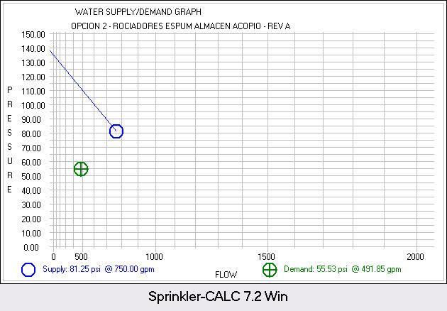
5 OPCION 2 - ROCIADORES ESPUM ALMACEN ACOPIO - REV A PAGE 1 HYDRAULIC CALCULATIONS AT SPECIFIED DENSITY THE FOLLOWING SPRINKLERS ARE OPERATING IN: [ ] TEST AREA 1 [ ] TEST AREA 2 [ ] TEST AREA 3 [ ] REMOTE AREA Elevation of sprinklers = Elevation above water test. REF. PT. K ELEV. FLOW PRESSURE ft gpm psi THE SPRINKLER SYSTEM FLOW IS gpm THE OUTSIDE HOSE FLOW AT REFERENCE POINT N0. 1 IS 0.00 gpm [ ] THE INSIDE HOSE [ ] RACK SPKLR'S. [ ] YARD HYDT. FLOW IS gpm THE MINIMUM DENSITY PROVIDED BY THIS SYSTEM IS gpm/sq. ft. THE FOLLOWING PRESSURES & FLOWS OCCUR ---> AT REF. PT. 1 <--- STATIC PRESSURE psi RESIDUAL PRESSURE psi AT gpm TOTAL SYSTEM FLOW gpm AVAILABLE PRESSURE psi AT gpm OPERATING PRESSURE psi AT gpm PRESSURE REMAINING psi THE ABOVE RESULTS INCLUDE psi FRICTION LOSS AT REF. PT. # 50 FOR A [ ] BACKFLOW PREVENTER [ ] METER [ ] DETECTOR CHECK VALVE [ ] OTHER DEVICE
6 OPCION 2 - ROCIADORES ESPUM ALMACEN ACOPIO - REV A PAGE 2 FITTING Equivalent Length per NFPA , '-' Indicates Equivalent Length. 'T' Indicates Threaded Fitting 1=45 Elbow, 2=90 Elbow, 3='T'/Cross, 4=Butterfly Valve, 5=Gate Valve, 6=Swing Check Valve ============================================================================================= FROM TO FLOW PIPE FITS EQV. H-W PIPE DIA. FRIC. ELEV. FROM TO DIFF (gpm) (ft) (ft) C TYPE (in) (psi) (psi) (psi) (psi) (psi) A MAX. VELOCITY OF ft./sec. OCCURS BETWEEN REF. PT. 51 AND 100 Sprinkler-CALC Release 7.2 Win By Walsh Engineering Inc. North Kingstown R.I. U.S.A.
7 H Y D R A U L I C C A L C U L A T I O N S C O V E R S H E E T OPCION 2 - ROCIADORES ESPUM ALMACEN ACOPIO - REV A STATIC PRESSURE (psi) RESIDUAL PRESSURE (psi) RESIDUAL FLOW (gpm) 750 NUMBER OF BOOSTER PUMPS 0 W A T E R S U P P L Y B O O S T E R P U M P S S P R I N K L E R S MAXIMUM SPACING OF SPRINKLERS (ft) 10 MAXIMUM SPACING OF SPRINKLER LINES (ft) 10 SPECIFIED DISCHARGE DENSITY (gpm/sq. ft.).3 THIS SPRINKLER SYSTEM WILL DELIVER A DENSITY OF.3 gpm/sq. ft. FOR A DESIGN AREA OF 3000 SQ. FT. OF FLOOR AREA THIS SYSTEM OPERATES AT A FLOW OF gpm AT A PRESSURE OF psi AT THE BASE OF THE RISER (REF. PT. %100) PIPES USED FOR THIS SYSTEM ====================================== 001 SCHEDULE 40
8
9 OPCION 3 - ALTA EXPANSION ALMACEN ACOPIO - REV A PAGE 1 HYDRAULIC CALCULATIONS AT SPECIFIED FLOW THE FOLLOWING SPRINKLERS ARE OPERATING IN: [ ] TEST AREA 1 [ ] TEST AREA 2 [ ] TEST AREA 3 [ ] REMOTE AREA Elevation of sprinklers = Elevation above water test. REF. PT. K ELEV. FLOW PRESSURE ft gpm psi THE SPRINKLER SYSTEM FLOW IS gpm THE OUTSIDE HOSE FLOW AT REFERENCE POINT N0. 1 IS 0.00 gpm [ ] THE INSIDE HOSE [ ] RACK SPKLR'S. [ ] YARD HYDT. FLOW IS 0.00 gpm THE FOLLOWING PRESSURES & FLOWS OCCUR ---> AT REF. PT. 1 <--- STATIC PRESSURE psi RESIDUAL PRESSURE psi AT gpm TOTAL SYSTEM FLOW gpm AVAILABLE PRESSURE psi AT gpm OPERATING PRESSURE psi AT gpm PRESSURE REMAINING psi THE ABOVE RESULTS INCLUDE psi FRICTION LOSS AT REF. PT. # 50 FOR A [ ] BACKFLOW PREVENTER [ ] METER [ ] DETECTOR CHECK VALVE [ ] OTHER DEVICE
10 OPCION 3 - ALTA EXPANSION ALMACEN ACOPIO - REV A PAGE 2 FITTING Equivalent Length per NFPA , '-' Indicates Equivalent Length. 'T' Indicates Threaded Fitting 1=45 Elbow, 2=90 Elbow, 3='T'/Cross, 4=Butterfly Valve, 5=Gate Valve, 6=Swing Check Valve ============================================================================================= FROM TO FLOW PIPE FITS EQV. H-W PIPE DIA. FRIC. ELEV. FROM TO DIFF (gpm) (ft) (ft) C TYPE (in) (psi) (psi) (psi) (psi) (psi) A MAX. VELOCITY OF 6.61 ft./sec. OCCURS BETWEEN REF. PT. 102 AND 901 Sprinkler-CALC Release 7.2 Win By Walsh Engineering Inc. North Kingstown R.I. U.S.A.
11 H Y D R A U L I C C A L C U L A T I O N S C O V E R S H E E T OPCION 3 - ALTA EXPANSION ALMACEN ACOPIO - REV A STATIC PRESSURE (psi) RESIDUAL PRESSURE (psi) RESIDUAL FLOW (gpm) 750 NUMBER OF BOOSTER PUMPS 0 W A T E R S U P P L Y B O O S T E R P U M P S S P R I N K L E R S MINIMUM FLOW PER SPRINKLER (gpm) 42 MINIMUM PRESSURE PER SPRINKLER (psi) THIS SYSTEM OPERATES AT A FLOW OF gpm AT A PRESSURE OF psi AT THE BASE OF THE RISER (REF. PT. %100) PIPES USED FOR THIS SYSTEM ====================================== 001 SCHEDULE 40
12
Calculation of Pipe Friction Loss
 Doc.No. 6122-F3T071 rev.2 Calculation of Pipe Friction Loss Engineering Management Group Development Planning Department Standard Pump Business Division EBARA corporation October 16th, 2013 1 / 33 2 /
Hydraulic Considerations for Citrus Microirrigation Systems 1
 Cir1425 Hydraulic Considerations for Citrus Microirrigation Systems 1 Brian Boman and Sanjay Shukla 2 Introduction Hydraulics is the study of the behavior of liquids as they move through channels or pipes.
TOTAL HEAD, N.P.S.H. AND OTHER CALCULATION EXAMPLES Jacques Chaurette p. eng., June 2003
 TOTAL HEAD, N.P.S.H. AND OTHER CALCULATION EXAMPLES Jacques Chaurette p. eng., www.lightmypump.com June 2003 Figure 1 Calculation example flow schematic. Situation Water at 150 F is to be pumped from a
Guidelines for the Installation of SYGEF Pipes, Fittings and Valves
 Guidelines for the Installation of SYGEF Pipes, Fittings and Valves Calculation of Length Changes Length changes which occur in SYGEF can be calculated in the usual manner, taking into consideration the
PIPING SYSTEMS. Pipe and Tubing Standards Sizes for pipes and tubes are standardized. Pipes are specified by a nominal diameter and a schedule number.
 PIPING SYSTEMS In this chapter we will review some of the basic concepts associated with piping systems. Topics that will be considered in this chapter are - Pipe and tubing standards - Effective and hydraulic
Purpose of Today s Presentation
 Chilled Water Distribution Systems APPA Institute for Facilities Management Dallas, TX January 19, 2017 1 Purpose of Today s Presentation To provide a broad understanding of chilled water distribution
Northern Lesson 2 Gear Pump Terminology. Gear Pump 101. Lesson 2: Gear Pump Terminology. When your reputation depends on it!
 Gear Pump 101 Lesson 2: Gear Pump Terminology When your reputation depends on it! Symbol Term Metric Unit Abbreviation US Customary Unit Abbreviation Conversion factor a A Area square millimeter mm2 square
LECTURE 6- ENERGY LOSSES IN HYDRAULIC SYSTEMS SELF EVALUATION QUESTIONS AND ANSWERS
 LECTURE 6- ENERGY LOSSES IN HYDRAULIC SYSTEMS SELF EVALUATION QUESTIONS AND ANSWERS 1. What is the head loss ( in units of bars) across a 30mm wide open gate valve when oil ( SG=0.9) flow through at a
Sprinkler Irrigation
 Sprinkler Irrigation Definition Pressurized irrigation through devices called sprinklers Sprinklers are usually located on pipes called laterals Water is discharged into the air and hopefully infiltrates
CVE 372 HYDROMECHANICS EXERCISE PROBLEMS
 VE 37 HYDROMEHNIS EXERISE PROLEMS 1. pump that has the characteristic curve shown in the accompanying graph is to be installed in the system shown. What will be the discharge of water in the system? Take
PumpTech Customer Education
 PumpTech Customer Education http://www.pumptechnw.com Bellevue Moses Lake Canby PumpTech Product Lines UL Listed Packaged Systems Two full time Mechanical Engineers Licensed in OR, WA & ID SolidWorks &
Chapter 6. Hydraulic cylinders/rams (linear motors), and Lines/fittings. - Transforms the flow of a pressurized fluid into a push or pull of a rod.
, and Lines/fittings. - Transforms the flow of a pressurized fluid into a push or pull of a rod.") Chapter 6. Hydraulic cylinders/rams (linear motors), and Lines/fittings - Transforms the flow of a pressurized fluid into a push or pull of a rod. 6. Single cting Rams Gravity, spring, etc. can force piston
Chapter 6. Hydraulic cylinders/rams (linear motors), and Lines/fittings - Transforms the flow of a pressurized fluid into a push or pull of a rod. 6. Single cting Rams Gravity, spring, etc. can force piston
Water Circuit Lab. The pressure drop along a straight pipe segment can be calculated using the following set of equations:
 Water Circuit Lab When a fluid flows in a conduit, there is friction between the flowing fluid and the pipe walls. The result of this friction is a net loss of energy in the flowing fluid. The fluid pressure
LECTURE 8. Hydraulic machines and systems II 2002 MIT PSDAM LAB
 LECTURE 8 Hydraulic machines and systems II Basic hydraulic machines & components Graphical Nomenclature Arrows show direction of flow Control Volume Pipe or hose with fluid flow Pipe or hose without fluid
ERRATA TO THE 2000 INTERNATIONAL PLUMBING CODE. Fourth Printing, October 2002
 ERRATA TO THE 2000 INTERNATIONAL PLUMBING CODE F i f t h P r i n t i n g, A u g u s t, 2 0 0 3 (Updated December 17, 2003) T a b l e 7 0 2. 2 U n d e r g r o u n d B u i l d i n g D r a i n a g e a n d
Chapter Four Hydraulic Machines
 Contents 1- Introduction. - Pumps. Chapter Four Hydraulic Machines (لفرع الميكانيك العام فقط ( Turbines. -3 4- Cavitation in hydraulic machines. 5- Examples. 6- Problems; sheet No. 4 (Pumps) 7- Problems;
WATER DISTRIBUTION NETWORKS
 WATER DISTRIBUTION NETWORKS CE 370 1 Components of Water Supply System 2 1 Water Distribution System Water distribution systems are designed to adequately satisfy the water requirements for a combinations
3301 East 120 th Avenue Assited Living & Memory Care
 UTILITY REPORT FOR 3301 East 120 th Avenue Assited Living & Memory Care 1 st Submittal January 23, 2016 2 nd Submittal March 04, 2016 Prepared for: 3301 E. 120 th Ave, LLC. 8200 E. Maplewood Ave., Suite
ME 309 Fluid Mechanics Fall 2010 Exam 2 1A. 1B.
 Fall 010 Exam 1A. 1B. Fall 010 Exam 1C. Water is flowing through a 180º bend. The inner and outer radii of the bend are 0.75 and 1.5 m, respectively. The velocity profile is approximated as C/r where C
Experiment (4): Flow measurement
: Flow measurement") Experiment (4): Flow measurement Introduction: The flow measuring apparatus is used to familiarize the students with typical methods of flow measurement of an incompressible fluid and, at the same time
Experiment (4): Flow measurement Introduction: The flow measuring apparatus is used to familiarize the students with typical methods of flow measurement of an incompressible fluid and, at the same time
Chapter 6. Losses due to Fluid Friction
 Chapter 6 Losses due to Fluid Friction 1 Objectives ä To measure the pressure drop in the straight section of smooth, rough, and packed pipes as a function of flow rate. ä To correlate this in terms of
Chapter Four fluid flow mass, energy, Bernoulli and momentum
 4-1Conservation of Mass Principle Consider a control volume of arbitrary shape, as shown in Fig (4-1). Figure (4-1): the differential control volume and differential control volume (Total mass entering
Chapter Four Hydraulic Machines
 Contents 1- Introduction. 2- Pumps. Chapter Four Hydraulic Machines (لفرع الميكانيك العام فقط ( Turbines. -3 4- Cavitation in hydraulic machines. 5- Examples. 6- Problems; sheet No. 4 (Pumps) 7- Problems;
Pumping Stations Design For Infrastructure Master Program Engineering Faculty-IUG
 umping Stations Design For Infrastructure Master rogram Engineering Faculty-IUG Lecture : umping Hydraulics Dr. Fahid Rabah Water and environment Engineering frabah@iugaza.edu The main items that will
Analysis Methods for Water Distribution Systems-3 rd Class )طرق تحليل أنظمة توزيع المياه( Dr. Sataa A. Al-Bayati (10-11)
طرق تحليل أنظمة توزيع المياه( Dr. Sataa A. Al-Bayati (10-11)") تسم هللا الزحمه الزحيم Analysis Methods for Water Distribution Systems-3 rd Class )طرق تحليل أنظمة توزيع المياه( Dr. Sataa A. Al-Bayati (10-11) Methods of analysis are: )المقاطغ( Sectioning.1 )االوثىب
تسم هللا الزحمه الزحيم Analysis Methods for Water Distribution Systems-3 rd Class )طرق تحليل أنظمة توزيع المياه( Dr. Sataa A. Al-Bayati (10-11) Methods of analysis are: )المقاطغ( Sectioning.1 )االوثىب
PUMP PERFORMANCE MEASUREMENTS Jacques Chaurette p. eng. April 2003
 PUMP PERFORMANCE MEASUREMENTS Jacques Chaurette p. eng. www.lightmypump.com April 003 Synopsis This article examines how to take flow and pressure measurement and then calculate the total head of a pump
Fluid Properties: := 1.35 cp liquid viscosoty. m 3 density of the flowing liquid. sg:= specific gravity of the flowing liquid. Pipe System Conditions:
 Control Valve Selection August 17 th 1997 Andrés Felipe Ortega Montoya Chemical Engineer - Universidad Pontificia Bolivariana - Medellín, Colombia. E - Mail: aortega@janua.upb.edu.co I originally obtained
Hydraulics and hydrology
 Hydraulics and hydrology - project exercises - Class 4 and 5 Pipe flow Discharge (Q) (called also as the volume flow rate) is the volume of fluid that passes through an area per unit time. The discharge
Fachgesprach 12. HVAC Pumps. For Project Managers
 Fachgesprach 12 HVAC Pumps For Project Managers WTF Philosophy: If you don t remember a certain formula, it's OK - you can always GoogleTheS h i t. But bad engineering CONCEPTS can hurt you. WTF Institute
Pipe Flow. Lecture 17
 Pipe Flow Lecture 7 Pipe Flow and the Energy Equation For pipe flow, the Bernoulli equation alone is not sufficient. Friction loss along the pipe, and momentum loss through diameter changes and corners
Applied Fluid Mechanics
 Applied Fluid Mechanics 1. The Nature of Fluid and the Study of Fluid Mechanics 2. Viscosity of Fluid 3. Pressure Measurement 4. Forces Due to Static Fluid 5. Buoyancy and Stability 6. Flow of Fluid and
405 Compact Orifice Series and 1595 Conditioning Orifice Plate Flow Test Data Book and Flow Handbook
 Reference Manual 405 Compact Orifice Series and 1595 Conditioning Orifice Plate Flow Test Book and Flow Handbook www.rosemount.com Reference Manual 405 and 1595 405 Compact Orifice Series and 1595 Conditioning
405 Compact Orifice Series and 1595 Conditioning Orifice Plate Flow Test Data Book and Flow Handbook
 405 Compact Orifice Series and 1595 Conditioning Orifice Plate Flow Test Book and Flow Handbook www.rosemount.com 405 Compact Orifice Series and 1595 Conditioning Orifice Plate Flow Test Book NOTICE Read
Eastlake Assited Living & Memory Care
 UTILITY REPORT FOR Eastlake Assited Living & Memory Care 1 st Submittal January 23, 2016 2 nd Submittal March 04, 2016 June 7, 2016 Final Submittal August 08, 2016 Prepared for: 3301 E. 120 th Ave, LLC.
Properties and Definitions Useful constants, properties, and conversions
 Properties and Definitions Useful constants, properties, and conversions gc = 32.2 ft/sec 2 [lbm-ft/lbf-sec 2 ] ρwater = 1.96 slugs/ft 3 γwater = 62.4 lb/ft 3 1 ft 3 /sec = 449 gpm 1 mgd = 1.547 ft 3 /sec
TECHNICAL IRRIGATION INFORMATION
 HANDBOOK TECHNICAL IRRIGATION INFORMATION THETHE HANDBOOK OFOFTECHNICAL A C oirrigation m p l e t e R e f e rinformation ence Source for the Professional A Complete Reference Source for the Professional
ME3560 Tentative Schedule Spring 2019
 ME3560 Tentative Schedule Spring 2019 Week Number Date Lecture Topics Covered Prior to Lecture Read Section Assignment Prep Problems for Prep Probs. Must be Solved by 1 Monday 1/7/2019 1 Introduction to
Backflow Prevention. Rule Update. Water Distribution Systems Workshop December 10, 2014
 Backflow Prevention Rule Update Water Distribution Systems Workshop December 10, 2014 Maria Lucente, P.E. Ohio Environmental Protection Agency Division of Drinking and Ground Waters Backflow Prevention
Flowmeter Discharge Coefficient Estimation
 Bankston 1 Flowmeter Discharge Coefficient Estimation Elizabeth Bankston Team 1 Abstract An Edibon FME18 Flow Meter demonstration system was used to obtain experimental values for this experiment. The
EXPERIMENT NO: F5. Losses in Piping Systems
 SJSU ME115 - THERMAL ENGINEERING LAB EXPERIMENT NO: F5 Losses in Piping Systems Objective One of the most common problems in fluid mechanics is the estimation of pressure loss. It is the objective of this
ME3560 Tentative Schedule Fall 2018
 ME3560 Tentative Schedule Fall 2018 Week Number 1 Wednesday 8/29/2018 1 Date Lecture Topics Covered Introduction to course, syllabus and class policies. Math Review. Differentiation. Prior to Lecture Read
P & I Design Limited. 2 Reed Street, Gladstone Industrial Estate, Thornaby, TS17 7AF. Tel: +44 (0) Fax: +44 (0)
 Fax: +44 (0)") ump Sizing & Rating USER MANUAL & I Design Limited Reed Street, Gladstone Industrial Estate, Thornaby, TS7 7AF. Tel: +44 (0) 64 67444 Fax: +44 (0) 64 66447 www.pidesign.co.uk Support: sales@pidesign.co.uk
ump Sizing & Rating USER MANUAL & I Design Limited Reed Street, Gladstone Industrial Estate, Thornaby, TS7 7AF. Tel: +44 (0) 64 67444 Fax: +44 (0) 64 66447 www.pidesign.co.uk Support: sales@pidesign.co.uk
Exam #2: Fluid Kinematics and Conservation Laws April 13, 2016, 7:00 p.m. 8:40 p.m. in CE 118
 CVEN 311-501 (Socolofsky) Fluid Dynamics Exam #2: Fluid Kinematics and Conservation Laws April 13, 2016, 7:00 p.m. 8:40 p.m. in CE 118 Name: : UIN: : Instructions: Fill in your name and UIN in the space
Pressure and Flow Characteristics
 Pressure and Flow Characteristics Continuing Education from the American Society of Plumbing Engineers August 2015 ASPE.ORG/ReadLearnEarn CEU 226 READ, LEARN, EARN Note: In determining your answers to
2.The lines that are tangent to the velocity vectors throughout the flow field are called steady flow lines. True or False A. True B.
 CHAPTER 03 1. Write Newton's second law of motion. YOUR ANSWER: F = ma 2.The lines that are tangent to the velocity vectors throughout the flow field are called steady flow lines. True or False 3.Streamwise
THE HANDBOOK OF TECHNICAL IRRIGATION INFORMATION
 THE HANDBOOK OF TECHNICAL IRRIGATION INFORMATION A Complete Reference Source for the Professional RESIDENTIAL & COMMERCIAL IRRIGATION Built on Innovation hunterindustries.com PREFACE Hunter s Handbook
Lesson 6 Review of fundamentals: Fluid flow
 Lesson 6 Review of fundamentals: Fluid flow The specific objective of this lesson is to conduct a brief review of the fundamentals of fluid flow and present: A general equation for conservation of mass
Basic Math Concepts for Water and Wastewater Operators. Daniel B. Stephens & Associates, Inc.
 Basic Math Concepts for Water and Wastewater Operators Topics Hierarchy of operations Manipulating equations Unit/dimensional analysis and conversion factors Electricity Temperature Geometry Flow hydraulics
Modeling of Head Loss Components in Water Distribution to a Group of Buildings
 J. Basic. Appl. Sci. Res., 3(1)34-351, 013 013, TextRoad Publication ISSN 090-4304 Journal of Basic and Applied Scientific Research www.textroad.com Modeling of Head Components in Water Distribution to
Chapter (6) Energy Equation and Its Applications
 Energy Equation and Its Applications") Chapter (6) Energy Equation and Its Applications Bernoulli Equation Bernoulli equation is one of the most useful equations in fluid mechanics and hydraulics. And it s a statement of the principle of conservation
Chapter (6) Energy Equation and Its Applications Bernoulli Equation Bernoulli equation is one of the most useful equations in fluid mechanics and hydraulics. And it s a statement of the principle of conservation
Plant Design LECTURE 8: REBOILER CIRCUIT DESIGN. Daniel R. Lewin Department of Chemical Engineering Technion, Haifa, Israel
 054410 Plant Design LECTURE 8: REBOILER CIRCUIT DESIGN Daniel R. Lewin Department of Chemical Engineering Technion, Haifa, Israel Ref: Kern, R. Thermosyphon Reboiler Piping Simplified, Hydrocarbon Processing,
405 Compact Orifice Series and 1595 Conditioning Orifice Plate Flow Test Data Book and Flow Handbook
 405 Compact Orifice Series and 1595 Conditioning Orifice Plate Flow Test Book and Flow Handbook www.rosemount.com 405 and 1595 405 Compact Orifice Series and 1595 Conditioning Orifice Plate Flow Test
THE APPLICATION OF THERMODYNAMICS TO PUMP SYSTEMS
 THE APPLICATION OF THERMODYNAMICS TO PUMP SYSTEMS.0 ENERGY AND THERMODYNAMIC PROPERTIES This chapter requires some introduction to thermodynamic properties and states. No need to panic, we will use only
TECHNICAL INFORMATION
 RMATION This section includes conversion factors, equivalents and formulas as they apply to golf course irrigation. The information is arranged by category to simplify and speed the process when making
FE Fluids Review March 23, 2012 Steve Burian (Civil & Environmental Engineering)
") Topic: Fluid Properties 1. If 6 m 3 of oil weighs 47 kn, calculate its specific weight, density, and specific gravity. 2. 10.0 L of an incompressible liquid exert a force of 20 N at the earth s surface.
Topic: Fluid Properties 1. If 6 m 3 of oil weighs 47 kn, calculate its specific weight, density, and specific gravity. 2. 10.0 L of an incompressible liquid exert a force of 20 N at the earth s surface.
LOSSES DUE TO PIPE FITTINGS
 LOSSES DUE TO PIPE FITTINGS Aim: To determine the losses across the fittings in a pipe network Theory: The resistance to flow in a pipe network causes loss in the pressure head along the flow. The overall
Fluid Flow Analysis Penn State Chemical Engineering
 Fluid Flow Analysis Penn State Chemical Engineering Revised Spring 2015 Table of Contents LEARNING OBJECTIVES... 1 EXPERIMENTAL OBJECTIVES AND OVERVIEW... 1 PRE-LAB STUDY... 2 EXPERIMENTS IN THE LAB...
Mechanical Engineering Programme of Study
 Mechanical Engineering Programme of Study Fluid Mechanics Instructor: Marios M. Fyrillas Email: eng.fm@fit.ac.cy SOLVED EXAMPLES ON VISCOUS FLOW 1. Consider steady, laminar flow between two fixed parallel
COURSE CODE : 3072 COURSE CATEGORY : B PERIODS/ WEEK : 5 PERIODS/ SEMESTER : 75 CREDIT : 5 TIME SCHEDULE
 COURSE TITLE : FLUID MECHANICS COURSE CODE : 307 COURSE CATEGORY : B PERIODS/ WEEK : 5 PERIODS/ SEMESTER : 75 CREDIT : 5 TIME SCHEDULE MODULE TOPIC PERIOD 1 Properties of Fluids 0 Fluid Friction and Flow
Big Hanaford Combined Cycle Plant. Calculation for Cooling Water System Transient Load Analysis. 6 November, 2001
 PAGE 1 OF Big Hanaford Combined Cycle Plant Calculation for Cooling Water System Transient Load Analysis 6 November, 2001 PAGE 2 OF CLIENT Transalta Energy Corporation PROJECT Big Hanaford Combined Cycle
Flow Switches. Liquid Flow Switches. McDonnell & Miller. Mounting Methods
 Liquid Flow Switches The flow of liquids in pipelines plays an important role in industry and commerce. Under most circumstances it is essential to know whether or not there is a flow in a pipeline, and
An Expression for Obtaining Total Heads for Lift Pump Selection
 American Journal of Engineering Research (AJER) e-issn : 2320-0847 p-issn : 2320-0936 Volume-03, Issue-06, pp-169-176 www.ajer.org Research Paper Open Access An Expression for Obtaining Total Heads for
Name: 10/21/2014. NE 161 Midterm. Multiple choice 1 to 10 are 2 pts each; then long problems 1 through 4 are 20 points each.
 NE 161 Midterm Multiple choice 1 to 10 are 2 pts each; then long problems 1 through 4 are 20 points each. 1. Which would have a higher mass flow rate out of a 1 ft 2 break, a. 200 psia subcooled water
CIVE HYDRAULIC ENGINEERING PART I Pierre Julien Colorado State University
 CIVE 401 - HYDRAULIC ENGINEERING PART I Pierre Julien Colorado State University Problems with and are considered moderate and those with are the longest and most difficult. In 2018 solve the problems with
Review of pipe flow: Friction & Minor Losses
 ENVE 204 Lecture -1 Review of pipe flow: Friction & Minor Losses Assist. Prof. Neslihan SEMERCİ Marmara University Department of Environmental Engineering Important Definitions Pressure Pipe Flow: Refers
Reynolds, an engineering professor in early 1880 demonstrated two different types of flow through an experiment:
 7 STEADY FLOW IN PIPES 7.1 Reynolds Number Reynolds, an engineering professor in early 1880 demonstrated two different types of flow through an experiment: Laminar flow Turbulent flow Reynolds apparatus
Fluid Mechanics II 3 credit hour. Fluid flow through pipes-minor losses
 COURSE NUMBER: ME 323 Fluid Mechanics II 3 credit hour Fluid flow through pipes-minor losses Course teacher Dr. M. Mahbubur Razzaque Professor Department of Mechanical Engineering BUET 1 Losses in Noncircular
1.060 Engineering Mechanics II Spring Problem Set 4
 1.060 Engineering Mechanics II Spring 2006 Due on Monday, March 20th Problem Set 4 Important note: Please start a new sheet of paper for each problem in the problem set. Write the names of the group members
EXPERIMENT No.1 FLOW MEASUREMENT BY ORIFICEMETER
 EXPERIMENT No.1 FLOW MEASUREMENT BY ORIFICEMETER 1.1 AIM: To determine the co-efficient of discharge of the orifice meter 1.2 EQUIPMENTS REQUIRED: Orifice meter test rig, Stopwatch 1.3 PREPARATION 1.3.1
SIZING 2 E DEFINITIONS AND UNITS OF MEASUREMENT 2.1 CALCULATION OF THE ACCUMULATOR 2.2
 SIZING 2 E 01-12 DEFINITIONS AND UNITS OF MEASUREMENT 2.1 CALCULATION OF THE ACCUMULATOR 2.2 DEFINITIONS AND UNITS OF MEASUREMENT 2.1 E 01-12 2.1.1 DEFINITIONS Po = nitrogen pre-charge pressure (relative
M E 320 Professor John M. Cimbala Lecture 24
 M E 30 Professor John M. Cimbala Lecture 4 Today, we will: Discuss pump performance curves Discuss how to match a pump and a piping system, and do some example problems. Pump Performance a. Pump performance
Backflow Prevention Rule Update
 Backflow Prevention Rule Update OTCO Compliance Workshop October 26, 2015 Maria Lucente, P.E. Ohio Environmental Protection Agency Division of Drinking and Ground Waters Backflow Prevention Rule Update
Information and slides provided by RFD
 Information and slides provided by RFD OBJECTIVES Define: Velocity Discharge Nozzle pressure Nozzle reaction OBJECTIVES Find Velocity when head is known Velocity when NP is known GPM using the discharge
INTERNAL FLOWS / FLOWS IN DUCTS
 Fluid and Particulate systems 4451 /018 INTERNAL FLOWS / FLOWS IN DUCTS Ron Zevenhoven ÅA Thermal and Flow Engineering ron.zevenhoven@abo.fi.1 Flow tube sections in series, in parallel, or branched RoNz
Frictional Losses in Straight Pipe
 2/2/206 CM325 Fundamentals of Chemical Engineering Laboratory Prelab Preparation for Frictional Losses in Straight Pipe Professor Faith Morrison Department of Chemical Engineering Michigan Technological
Fluid Statics, Hydrodynamics and Hydraulic Machines
 Fluid Statics, Hydrodynamics and Hydraulic Machines Bobby Rauf 1 Fluid Facts 1) Liquids and gases can both be categorized as fluids. 2) Liquid fluids are assumed be incompressible. 3) Gaseous fluids are
The Expansibility Factor Equations in ISO and ISO : Do They Deliver What They Promise?
 The Expansibility Factor Equations in ISO 567-2 and ISO 567-4: Do They Deliver What They Promise? Michael Reader-Harris, NEL INTRODUCTION The expansibility factor equations in ISO 567-2:2003 [] and ISO
Viscous Flow in Ducts
 Dr. M. Siavashi Iran University of Science and Technology Spring 2014 Objectives 1. Have a deeper understanding of laminar and turbulent flow in pipes and the analysis of fully developed flow 2. Calculate
Heating, Ventilating, Air Conditioning and Refrigerating, Sixth Edition, First Printing ERRATA
 1 Heating, Ventilating, Air Conditioning and Refrigerating, Sixth Edition, First Printing ERRATA (Items in blue added August 14, 2007; previous revision was December 3, 2004) Inside Front Cover: Conversion
Piping Systems and Flow Analysis (Chapter 3)
") Piping Systems and Flow Analysis (Chapter 3) 2 Learning Outcomes (Chapter 3) Losses in Piping Systems Major losses Minor losses Pipe Networks Pipes in series Pipes in parallel Manifolds and Distribution
Piping Systems and Flow Analysis (Chapter 3) 2 Learning Outcomes (Chapter 3) Losses in Piping Systems Major losses Minor losses Pipe Networks Pipes in series Pipes in parallel Manifolds and Distribution
V-Cone Flowmeter DATASHEET
 V-Cone Flowmeter ATASHEET JUNHO 013 IntraCone Cone Flow Meter Type: ICM etail: Cone-Element Technical Information 05/011 FLOW THE SPECIALIST IN LEVEL AN FLOW Cone Flow Meter Technical Information Intra-Automation
STEADY FLOW THROUGH PIPES DARCY WEISBACH EQUATION FOR FLOW IN PIPES. HAZEN WILLIAM S FORMULA, LOSSES IN PIPELINES, HYDRAULIC GRADE LINES AND ENERGY
 STEADY FLOW THROUGH PIPES DARCY WEISBACH EQUATION FOR FLOW IN PIPES. HAZEN WILLIAM S FORMULA, LOSSES IN PIPELINES, HYDRAULIC GRADE LINES AND ENERGY LINES 1 SIGNIFICANCE OF CONDUITS In considering the convenience
Sourabh V. Apte. 308 Rogers Hall
 Sourabh V. Apte 308 Rogers Hall sva@engr.orst.edu 1 Topics Quick overview of Fluid properties, units Hydrostatic forces Conservation laws (mass, momentum, energy) Flow through pipes (friction loss, Moody
An overview of the Hydraulics of Water Distribution Networks
 An overview of the Hydraulics of Water Distribution Networks June 21, 2017 by, P.E. Senior Water Resources Specialist, Santa Clara Valley Water District Adjunct Faculty, San José State University 1 Outline
FLOW MEASUREMENT IN PIPES EXPERIMENT
 University of Leicester Engineering Department FLOW MEASUREMENT IN PIPES EXPERIMENT Page 1 FORMAL LABORATORY REPORT Name of the experiment: FLOW MEASUREMENT IN PIPES Author: Apollin nana chaazou Partner
Chapter 3 Bernoulli Equation
 1 Bernoulli Equation 3.1 Flow Patterns: Streamlines, Pathlines, Streaklines 1) A streamline, is a line that is everywhere tangent to the velocity vector at a given instant. Examples of streamlines around
Lecture 4. Lab this week: Cartridge valves Flow divider Properties of Hydraulic Fluids. Lab 8 Sequencing circuit Lab 9 Flow divider
 91 Lecture 4 Lab this week: Lab 8 Sequencing circuit Lab 9 Flow divider Cartridge valves Flow divider Properties of Hydraulic Fluids Viscosity friction and leakage Bulk modulus Inertance Cartridge Valves
CIVE HYDRAULIC ENGINEERING PART II Pierre Julien Colorado State University
 1 CIVE 401 - HYDRAULIC ENGINEERING PART II Pierre Julien Colorado State University Problems with and are considered moderate and those with are the longest and most difficult. In 2018 solve the problems
University of Minnesota St. Anthony Falls Hyd.rauJ.ic Laboratory. Project Report No. 174 MODEL STUDY OF TEE VAN LARE OVERFLOW DISTRIBUTION STRUCTURE
 University of Minnesota St. Anthony Falls Hyd.rauJ.ic Laboratory Project Report No. 174 MODEL STUDY OF TEE VAN LARE OVERFLOW DISTRIBUTION STRUCTURE by John M. Killen a:nd.,_. Charles C. s. Song Prepared
Tanjung Priok GFPPEP. Presentation and discussion, 22 October 2009 PT. PLN (Persero) Jasa Enjiniring Office Jl. KS Tubun I/2 Petamburan, Jakarta
 Jasa Enjiniring Office Jl. KS Tubun I/2 Petamburan, Jakarta") Tanjung Priok GFPPEP Presentation and discussion, 22 October 2009 PT. PLN (Persero) Jasa Enjiniring Office Jl. KS Tubun I/2 Petamburan, Jakarta prepared by Department of Civil and Environmental Engineering
Tanjung Priok GFPPEP Presentation and discussion, 22 October 2009 PT. PLN (Persero) Jasa Enjiniring Office Jl. KS Tubun I/2 Petamburan, Jakarta prepared by Department of Civil and Environmental Engineering
LEAKLESS COOLING SYSTEM V.2 PRESSURE DROP CALCULATIONS AND ASSUMPTIONS
 CH-1211 Geneva 23 Switzerland EDMS No. ST/CV - Cooling of Electronics & Detectors GUIDE LEAKLESS COOLING SYSTEM V.2 PRESSURE DROP CALCULATIONS AND ASSUMPTIONS Objectives Guide to Leakless Cooling System
FLUID MECHANICS D203 SAE SOLUTIONS TUTORIAL 2 APPLICATIONS OF BERNOULLI SELF ASSESSMENT EXERCISE 1
 FLUID MECHANICS D203 SAE SOLUTIONS TUTORIAL 2 APPLICATIONS OF BERNOULLI SELF ASSESSMENT EXERCISE 1 1. A pipe 100 mm bore diameter carries oil of density 900 kg/m3 at a rate of 4 kg/s. The pipe reduces
Signature: (Note that unsigned exams will be given a score of zero.)
") Neatly print your name: Signature: (Note that unsigned exams will be given a score of zero.) Circle your lecture section (-1 point if not circled, or circled incorrectly): Prof. Dabiri Prof. Wassgren Prof.
Neatly print your name: Signature: (Note that unsigned exams will be given a score of zero.) Circle your lecture section (-1 point if not circled, or circled incorrectly): Prof. Dabiri Prof. Wassgren Prof.
CEE 481 Midterm Exam 1b, Aut 2008
 CEE 481 Midterm Exam 1b, Aut 8 Name: how all your work. If you can answer a question by inspection of the data, write a sentence stating your reasoning. A NUMERICAL ANWER WITHOUT ANY EXPLANATION WILL RECEIVE
PVC - WHITE PRESSURE FITTINGS PRODUCTS PRICE LIST INCLUDES: PVC SCHEDULE 40, CLASS 125, POOL/SPA, LASCOTITE, ULTRAFIX REPAIR COUPLINGS PRICE GROUP
 PRICE GROUP DESCRIPTION 01 SCH 40 PVC through 8 91 SCH 40 PVC 10" AND LARGER 96 CLASS 125 10 & 12 09 POOL AND SPA 14 LASCOTITE 15 ULTRAFIX REPAIR COUPLING DISCOUNT MULTIPLIER PRODUCTS PVC - WHITE PRESSURE
EGN 3353C Fluid Mechanics
 Lecture 8 Bernoulli s Equation: Limitations and Applications Last time, we derived the steady form of Bernoulli s Equation along a streamline p + ρv + ρgz = P t static hydrostatic total pressure q = dynamic
n = Kinematic viscosity (cst) SG = specific gravity or 1 Poise = 100 cp 1 Stoke = 100 cst Q = capacity (m 3 /s) A = tube area (m 2 ) or
 SG = specific gravity or 1 Poise = 100 cp 1 Stoke = 100 cst Q = capacity (m 3 /s) A = tube area (m 2 ) or") Fmulas Designation Fmula Comments Product Viscosity n = m r n = Kinematic viscosity (mm /s) m = Absolute viscosity (mpa.s) n = m SG n = Kinematic viscosity (cst) m = Absolute viscosity (cp) m = n SG 1
Fmulas Designation Fmula Comments Product Viscosity n = m r n = Kinematic viscosity (mm /s) m = Absolute viscosity (mpa.s) n = m SG n = Kinematic viscosity (cst) m = Absolute viscosity (cp) m = n SG 1
PUMP SYSTEM ANALYSIS AND SIZING. BY JACQUES CHAURETTE p. eng.
 PUMP SYSTEM ANALYSIS AND SIZING BY JACQUES CHAURETTE p. eng. 5 th Edition February 2003 Published by Fluide Design Inc. www.fluidedesign.com Copyright 1994 I TABLE OF CONTENTS Introduction Symbols Chapter
4 Mechanics of Fluids (I)
") 1. The x and y components of velocity for a two-dimensional flow are u = 3.0 ft/s and v = 9.0x ft/s where x is in feet. Determine the equation for the streamlines and graph representative streamlines in
1. The x and y components of velocity for a two-dimensional flow are u = 3.0 ft/s and v = 9.0x ft/s where x is in feet. Determine the equation for the streamlines and graph representative streamlines in
CEE 3310 Control Volume Analysis, Oct. 7, D Steady State Head Form of the Energy Equation P. P 2g + z h f + h p h s.
 CEE 3310 Control Volume Analysis, Oct. 7, 2015 81 3.21 Review 1-D Steady State Head Form of the Energy Equation ( ) ( ) 2g + z = 2g + z h f + h p h s out where h f is the friction head loss (which combines