IR status. 2009/3/19 M. Iwasaki For Super-KEKB MDI group U. Tokyo, Tohoku U., and KEK
|
|
|
- Maximilian Miles
- 5 years ago
- Views:
Transcription
1 IR status 2009/3/19 M. Iwasaki For Super-KEKB MDI group U. Tokyo, Tohoku U., and KEK
2 Introduction 2 Super-KEKB High luminosity experiment To increase the luminosity, machine parameters will drastically change Issues of the IR design: 1. Beam background High beam current / High power SR emission 2. Heating of IR components Short bunch length / High current / High power SR 3. Assembly of inner detectors, beam pipe, and final magnets Place final Q magnets closer to IP IR design is very important in Super-KEB

3 From KEKB to Super-KEKB 1 Y.Funakoshi Kick off meeting 3
4 From KEKB to Super-KEKB 2 4 Y.Funakoshi Kick off meeting IP QCS distance : ~60cm ~40cm (L side) ~75cm ~65cm (R side) There is little space in L-side We must think about the detector assembly
5 Two machine parameter options To avoid the beam instability by Coherent Synchrotron Radiation (CSR), we must design the longer bunch length for LER Oide-san s talk Currently 2 machine options are considered: High-current and Nano-beam High current option (LER/HER) Nano-beam option (LER/HER) Beam current I (A) High current : 9.4/ /1.55 Bunch length σ z (mm) Short bunch length : 5/3 6/6 Emittance ε x (nm) ε y (nm) 24/ /0.09 Low emittance : 1/ /0.025 β x β y (nm) 200/200 3/6 Small β : 35/ /0.22 Beam size σ y 0.85/0.73 (µm) Small beam size : 35/71 (nm) Distance btw IP and QCS ~40cm (L) / ~65cm (R) 30-40cm each?? High-current option Higher SR BG / HOM heating Nano-beam option IR assembly is difficult 5
6 Current status of the IR studies Detector IR group status 1. Beam Background SR BG simulation studies (Tokyo / KEK) Other BG sources not yet 2. Heating of IR components HOM heating studies (Tohoku / KEK) SR heating calculation (KEK) H. Yamaoka-san s talk 3. Detector assembly Must consider the detector support / assembly design We also ask machine talks directly related to the detector: - IR optics - QCS design - IR region assembly 6
7 Machine talks IR optics QCS design IR region assembly H.Koiso (KEK) N.Ohuchi (KEK) K.Kanazawa(KEK) 7
8 IR Optics 2nd Open Meeting of the SuperKEKB Collaboration Meeting Mar. 17, 2009 Haruyo Koiso 8
9 High Current Option H.Koiso (KEK) K. Ohmi Y. Funakoshi
 - To take care of the beam-beam effect, βx* 20 40cm Luminosity will decrease by ~20%, very large beam size - βx* 40")

10 Optics with New Quads H.Koiso (KEK) - To take care of the beam-beam effect, βx* 20 40cm Luminosity will decrease by ~20%, very large beam size - βx* 40 20cm again with new quads / reduce β at QC2 1.9K superconducting and permanent quads. Additional horizontal focusing quads for HER. At present, only L-side is acceptable from the view point of σ x and SR fan. Old: HER BX*/BY*= 40/0.3 cm R-side New:HER BX*/BY*= 20/0.5 cm L-side HER beam QC2L QC1L QCSLF QCSLD QCSRD QCSRF QC1R QC2R QC2L QC1L QCSL QCSR QC1R QC2R
11 Present Layout H.Koiso (KEK) QC2RE QC2LP QC1RE QCSL (1.9K) QCSR LER beam HER beam QC2LE QC1LE QCSLFE (permanent) QC2RP L-side: New 1.9K quadrupole (QCSL), and Additional horizontal focusing permanent quadrupole (QCSLF) in HER


12 LER Optics H.Koiso (KEK) βx* is still 40 cm, which is limited by R-side. Only L-side with a new superconducting quadrupole. ( 1.9K QCSL) Field gradient of QCS s is optimized for LER. IR: BX*/BY*= 40/0.3 cm Tsukuba: BX*/BY*= 40/0.3 cm R-side L-side IP QC2R QCSR QCSL QC2L QCSL Field gradient 53.0 T/m Distance (IP-Mag. center) 0.66 m Effective length 0.44 m
 - βx* is 40 cm - Only L-side with new quadrupoles.")

13 HER Optics H.Koiso (KEK) - βx* is 40 cm - Only L-side with new quadrupoles. ( 1.9K QCSL + permanent QCSLF) IR: BX*/BY*= 40/0.5 cm Tsukuba: BX*/BY*= 40/0.5 cm R-side R-side L-side IP QC2R QC1R QCSRD QCSLD QCSLF QC1L QC2L QCSLF Field gradient 44.3 T/m
14 Low Emittance Option H.Koiso (KEK) Y. Funakoshi
15 Italian version of IP BX*/BY* = 20 /.200 mm H.Koiso (KEK) LER SD pair SD pair for local chromaticity correction A. Morita Distance between IP and final-q 40cm in both L and R sides
16 Summary H.Koiso (KEK) For high current option, we have not yet found a realistic solution of β x * =20 cm. At present, β x * remains 40 cm. Design of low emittance option has just started. Geometry of IR beam lines New layout with 60 mrad crossing angle
17 17
18 N.Ohuchi (KEK) 18
19 N.Ohuchi (KEK)
20 N.Ohuchi (KEK)
21 N.Ohuchi (KEK) 21
22 IP Region Assembly Ken-ichi Kanazawa KEK 18 March

23 KEKB K.Kanazawa (KEK) Condition: Vacuum chambers are separate from QCS cryostats. Step 1: Connect the front half of QCSL chamber and QCSR chamber to IP chamber that is already set at the interaction point. (The end flange of QCSR chamber is temporally removed.) Step 2: Move forward QCS cryostats. Step 3: Connect the end half of QCSL chamber with a magic flange to the front half. Attach the end flange to QCSR chamber.
24 KEKB Condition: Vacuum chambers are separate from QCS cryostats. CDC SVD+IP chamber
25 KEKB Condition: Vacuum chambers are separate from QCS cryostats. CDC QCS chamber Step 1: Connect the front half of QCSL chamber and QCSR chamber to IP chamber that is already set at the interaction point. (The end flange of QCSR chamber is temporally removed.)
26 KEKB Condition: Vacuum chambers are separate from QCS cryostats. CDC QCS chamber Step 1: Connect the front half of QCSL chamber and QCSR chamber to IP chamber that is already set at the interaction point. (The end flange of QCSR chamber is temporally removed.)
27 KEKB Condition: Vacuum chambers are separate from QCS cryostats. QCS cryostat CDC Step 2: Move forward QCS cryostats. Step 3: Connect the end half of QCSL chamber with a magic flange to the front half. Attach the end flange to QCSR chamber.
28 KEKB Condition: Vacuum chambers are separate from QCS cryostats. CDC Step 2: Move forward QCS cryostats. Step 3: Connect the end half of QCSL chamber with a magic flange to the front half. Attach the end flange to QCSR chamber.

29 SuperKEKB high-current option K.Kanazawa (KEK) Condition: QCSLD cryostat and QCSL chamber forms a single body to ensure a thermal insulation space. Connecting flanges between QCSLD cryostat and IP chamber becomes inaccessible in CDC. Step 1: Assemble IP chamber and SVD in the front face of QCSLD cryostat in the retreat position. Step 2: Move forward QCSLD cryostat and SVD assembly. Step 3: Connect QCSR chamber. Step 4: Move forward QCSR cryostat.
30 SuperKEKB nano-beam option K.Kanazawa (KEK) Condition: In both QCSL and QCSR, their cryostat and the vacuum chamber (will) form a single body. Connecting flanges between both cryostats and IP chamber becomes inaccessible in CDC. Off-site assembly will include both cryostats, IP chamber, SVD, and CDC.!! OR A sort of automatic flange connecting system must be invented.??? (If this is invented, IP chamber and SVD can be always set at the IP beforehand.)
31 Summary K.Kanazawa (KEK) Design of QCS cryostat Both QCS cryostats are separate from vacuum chambers. In one QCS, the cryostat forms a single body with the vacuum chamber. Solution to assemble KEKB procedure. Assemble IP chamber and SVD in the front face of one QCS cryostat in the retreat position. OR In both QCS s, the cryostat forms a single body with the vacuum chamber. Automatic flange connecting system. Off-site assembly including both cryostats, IP chamber, SVD, and CDC. OR Automatic flange connecting system.
32 Detector BG / heating Upstream SR simulation SR Heating Calculation Backscattering SR simulation M.Iwasaki (Tokyo) H.Yamaoka (KEK) C.Ng (Tokyo)
33 Upstream SR simulation studies SR power is much higher than current KEKB, then we start from SR BG estimation 1. Design the IP beam-pipe to avoid HER SR direct hits to the detector 2. Study of the energy deposit to the IP beam-pipe For the SR BG study, we construct the beam line simulation based on GEANT4. Simple beam pipe + 1 st layer SVD + B-field of Q-magnets
34 Beam pipe design S.Uno LER Be part Au 10µm t Be 2mm t Inner diameter 30mm We put the beam pipe in our simulation SR Mask Au Base length 4mm Height 4mm Inner diameter 22mm HER 30mrad 30 IP Au straight part Au 5mm t Inner diameter 30mm Length 20mm Au Taper part Au 5mmt 30mrad taper Length 300mm
35 MAC Feb.10, 2009 Based on the GEANT4 simulation, SR BG has been studied 1. Upstream SR - Design of the IP beam-pipe to avoid SR from HER To avoid the SR direct hit, we should Locate the beam pipe parallel to HER (22mrad from Belle solenoid), and Put a 4mm height SR mask - Study of the energy deposit to the IP beam-pipe The energy deposit from HER SR will be ~1kW (SR mask) ~1kW (taper) 1kW deposit to the 4mm mask makes ~500 degree temperature rise It is very hard to cool the beam pipe 2. Backscattered SR We need more MC statistics to study in detail. We try to minimize the BG effect in our beam-pipe design, but SR power is so high that we cannot cool the beam-pipe New super-kekb machine parameters with lower SR power are highly appreciated
36 New super-kekb optics(1012a) New super-kekb optics has just been delivered - Beam size at the Q-magnet QC1L / QC2L : ½ of the current one - B-field of the Q-magnet QC1L : x1.6 of the current one QC2L : same - Same magnet length In total, SR power is reduced to 80% (QC1L) or 25% (QC2L) of the current one We ll re-estimate the SR BG based on the new optics
37 Energy deposit from SR HER SR Mask 82W HER taper 60W New optics (1012a) Gaussian beam 5σ tail cut LER SR Mask 18W LER taper 97W IP beam-pipe 17W - We still have 100W Energy deposit at SR mask. See heating calculation by Yamaoka-san OLD optics (sqrt 2σ beam) HER: SR Mask 0.73kW HER taper 0.69kW LER : SR Mask 20W LER taper 75W IP beam-pipe 15W
38 SR Heating calculation Temperature on the B.P. due to an influence of SR has been calculated. Configuration-A (Single Be-pipe) H.Yamaoka (KEK) Configuration-B (Double Be-pipe tube) Au: t5mm Gap 0.5mm Be:t0.35mm Be:t0.5mm Au: t0.01mm I.D O.D I.D O.D
39 Calculation-B (Double Be-tube) H.Yamaoka (KEK) Au: t5mm Gap 0.5mm Be:t0.35mm Be:t0.5mm Au: t0.01mm I.D O.D I.D O.D Outer surface of the Au-Beam Pipe. 3000W/m In the Be-gap. 3000W/m Outer surface of Be-gap. 5W/m Inside of the B.P. 0W/m 2 1. Outer surface of the Au-Beam Pipe. 3000W/m 2 25 Assumption: Cooling position (Be-Gap + Outer surface of the Au-pipe) 39
 Heat convection -")


40 Results (Double Be-tube) H.Yamaoka (KEK) Heat convection - Outer surface of the Au-B.P. 3000W/m Inside of Be-gap. 3000W/m Inside of the B.P. 0W/m 2 Max. temp. vs. Cooling ability. Max
 In case of 3000W/m 2 C, 25degC; - The maximum temperature is appeared on the SR mask.")
41 Conclusion H.Yamaoka (KEK) Temperature rise on the B.P. has been calculated with two kinds of (Double Be-pipe) Au: t5mm Gap 0.5mm Be:t0.35mm Be:t0.5mm Au: t0.01mm I.D O.D I.D O.D Max. temp. vs. Cooling ability. (Double Be-pipe) In case of 3000W/m 2 C, 25degC; - The maximum temperature is appeared on the SR mask. 87degC - Temperature at other SR hit positions are around 30-35degC. 5-10degC of temperature rise. 41
 By constructing the realistic beam pipe in our simulation, we have studied the back scattered SR BG effect.")
42 Back scattered SR simulation Clement Ng (U. Tokyo) By constructing the realistic beam pipe in our simulation, we have studied the back scattered SR BG effect. - Beam Pipe material 6mm Cu + 10um Au - Construct ±10m from IP - Input SR data generated in the upstream SR studies
 E deposit (kev) C.")
 z (mm) E (kev) New optics")
43 x (mm) HER SR simulation Hit position z vs x (mm) E deposit (kev) C.Ng (Tokyo) 43 Old optics QC1R QCSR HER taper IP HER beam 200keV x (mm) z (mm) E (kev) New optics SR mask 200keV z (mm) E (kev)
 Vertical scale is scaled for 1-bunch beam, Scale factor = 100 New optics Hit")

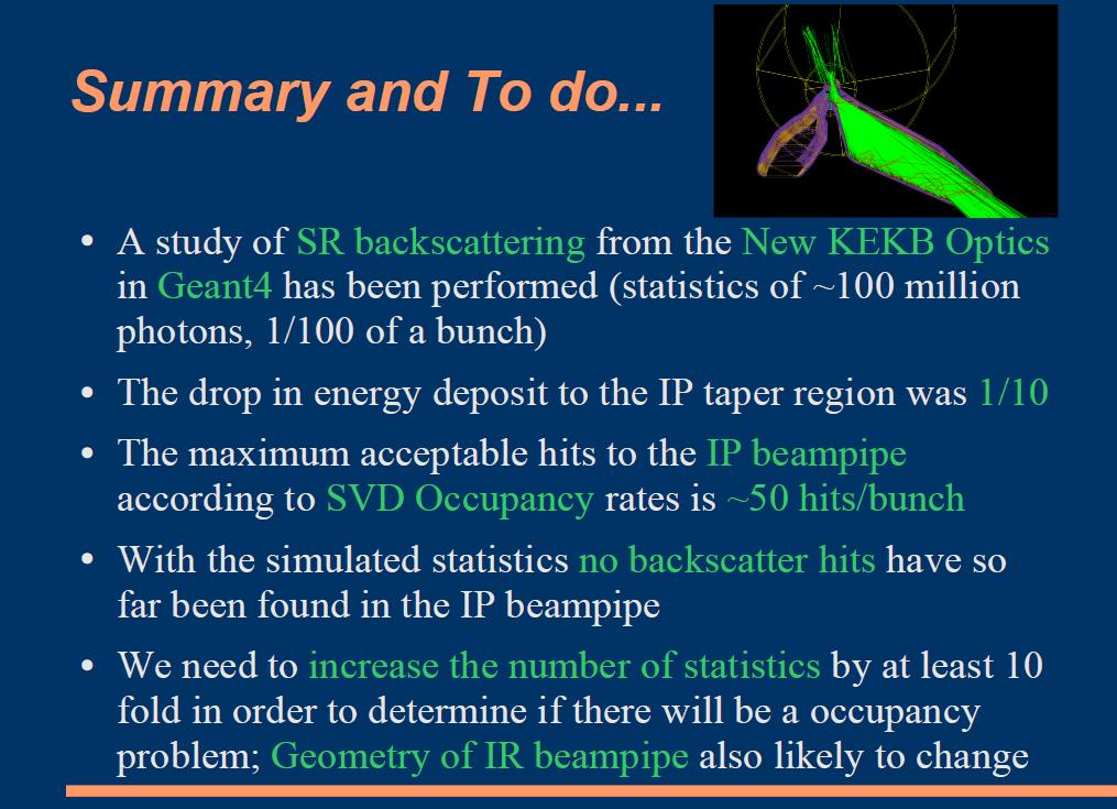
44 Back scattered photons at IP HER IP region (E SR >20keV) C.Ng (Tokyo) Vertical scale is scaled for 1-bunch beam, Scale factor = 100 New optics Hit position z(mm) Energy (kev) There are no entries in the IP Be region We cannot evaluate the SVD occupancy because MC statistics is too small. After increasing the statistics, we ll study the SVD occupancy
45 Summary Machine status - Designing of the nano-beam option is just started - New 1.9K QCS design has been developed - Little space in L-side (High-current) or both (nano-beam) 2. Must consider the detector/machine assembly QCS cryostat, beam pipe, and SVD might be integrated 3. SR simulations / heating calculation have been carried out Design of the cooling system, other sources of the BG There are many things to do for the MDI group New contributions are highly appreciated!!
46 Back up
47 Relationship between s-belle and Super-KEKB In Super-KEKB, crossing angle will be increased : 22mrad 30mrad e - KEKB / Super-KEKB HER(e - ) axis will not change 8mrad 22mrad HER LER e + KEKB, Belle solenoid Belle solenoid will not change e + Super KEKB LER(e + ) axis will rotate by 8mrad (QCS magnets will be set parallel to Belle solenoid) Belle beam pipe (and SVD??) axis at Super-KEKB - Belle solenoid - Center of the LER and HER (7mrad from Belle solenoid) - HER axis (22mrad from Belle solenoid)
48 Dynamic beam-beam effect at Super-KEKB Y.Funakoshi Emittance ε (wo dynamic effect) β (wo dynamic effect) ε (with dynamic effect) β (with dynamic effect) 5 times higher ε, 10 times smaller β in x Dynamic effect at Super-KEKB is very strong
49 Tow Options High current, crab crossing, large beam-beam parameter. A solution for β*x = cm Low emittance, low β*, nano-beam. Just started. Crossing angle mrad


50 Large Dynamic Effects The beam-beam effect must be taken into account in evaluation of physical apertures. Horizontal beam parameters change significantly with ξ x0 = and ν x =.505, β x * cm ε x nm Example: HER BX*/BY*= 20/0.5 cm w/o beam-beam y Y. Funakoshi w beam-beam ~1491m X ~148m HER beam
51 Physical Aperture Requirement : 5 σ x with beam-beam effect Larger than injection aperture. σ x must be decreased at QC2LE (HER) and QC2RE (HER). SR fan from 3σ x and 3σ x should also be considered. Increased β x * cm Luminosity will decrease by ~20 %.
52 Injection Acceptance Injection acceptance is evaluated: HER/LER 4.5E-6/7.5E-6 m w/o Damping Ring HER/LER 1.9E-6/2.6E-6 ~1.0E-6 m with Damping Ring M. Kikuchi
53 Dynamic aperture Italian version of IP A. Morita
54 Copper duct 50 µm gold plating LER Overview (1) Bellows BPM SR on the chamber wall ~25 kw (~1m) Bellows BPM? Bellows (no space!) HER Warm bore, the vacuum chambers are independent from the cryostat. Warm bore, the vacuum chamber is fixed to the cryostat Pumps are not fixed yet. Kanazawa
55 Copper duct 50 micron gold plating Bellows BPM Overview (2) Bellows BPM in the cryostat HER vacuum chamber must have a clearance against the direct SR from QCSR as far as 10 m from the IP. HER Warm bore ~80K cold bore Bellows between the cryostat and the vacuum ducts Kanazawa

56 HER simulation QCSR Taper QCSL e+ e- γ SR mask Beam pipe QC1L SVD HER beam
57 E (GeV) Energy deposit from upstream SR HER SR mask 2σ beam HER taper HER beam E (GeV) LER LER taper SR mask LER beam Total E deposit to the IP beam pipe HER ~18000GeV/bunch 1.4kW LER ~1400GeV/bunch 110W z (cm)
58 Energy deposit from SR HER SR Mask 0.73kW HER taper 0.69kW 2σ beam LER SR Mask 20W LER taper 75W IP beam-pipe 15W We have ~1kW Energy deposit at 4mm height SR mask...

59 HER beam-line simulation QC2R QC1R Taper e+ e- γ QCSR SR mask QCSL Beam pipe QC1L QC2L SVD HER beam
60 E (GeV) Energy deposit from upstream SR HER SR mask Tail cut : 5σ HER taper HER beam E (GeV) LER LER taper SR mask LER beam Total E deposit to the IP beam pipe HER ~1750GeV/bunch 140W (old: 1.4kW) LER ~1650GeV/bunch 130W (old: 110W) z (cm)
61 Beam IR Q-magnets IP HER Beam HER QC2R QC1R QCSR QCSL QC1L QC2L OLD optics New optics 74.5mm (5σ x ) 69.0 (5σ x ) LER Beam LER QC2R QC1R QCSR QCSL QC1L QC2L OLD New 63.9 (5σ x ) 66.3 (5σ x ) mm

62 LER beam-line simulation QC2L QCSR QCSL LER beam QC2R e+ e- γ
63 HER upstream SR energy 5σ beam QC1 New optics QC2 New optics 100 kev 100 kev Energy(keV) Energy(keV) QC1 Old optics QC2 Old optics The SR energy from HER is still high We don t want the direct hits from HER SR (Vertical scale: Scaled for 1-bunch beam)
64 SR hit to the IP beam pipe LER HER x (cm) LER beam LER taper IP beam pipe SR mask x (cm) HER taper HER beam z (cm) SR mask z (cm) y (cm) y (cm) RMS y = 0.5mm RMS y = 1.2mm z (cm) z (cm)
65 Summary 1. Simulation studies for the Super-KEKB high-current option - There expected huge energy deposit of ~1kW from HER SR in the old version Super-KEKB design - With the current new optics, it is decreased to ~100W (which is x10 of the current KEKB) - Detailed heating calculation / simulation is needed to design the cooling system (see Yamaoka-san s talk) - We need to start the other BG source studies 2. We will start the Super-KEKB nano-beam option studies Lower SR BG and HOM power are expected Is it possible to use the smaller radius beam-pipe?

66 Distribution of heat load 50W 18W 35W ϕ=±π 40W 17W ϕ=0 18W 35W 25W 60W 50W 35W 66

 1. 2.")
67 Configuration of B.P. Be-pipe)
: 319 216 Specific heat (J/kg ): 128 1925 68")
68 Other assumptions Outer surface of the B.P. is cooled by liquid. Heat convection - Outer surface of the B.P. 3000W/m 2, 25 Boundaries are ideally connected Inside of the B.P. 0W/m Au Be Thermal conductivity (W/m ): Specific heat (J/kg ):
 If no")


69 Results Be-pipe) If no cooling were done, Outer surface of the B.P. 3000W/m 2, 25 Max. 80 Max. 700degC Max. temp. vs. Cooling ability. 69
70
71 IR studies IR group meeting is held every other week U. Tokyo, Tohoku U., KEK Belle and KEKB team 71
Design of Superconducting Magnet System for SuperKEKB Interaction Region
 Design of Superconducting Magnet System for SuperKEKB Interaction Region Norihito Ohuchi On behalf of SuperKEKB Accelerator Gp and BNL SC Magnet Gp 2013/9/29-10/4 NA-PAC 2013 1 Contents 1. SC magnet system
Final-Focus Superconducting Magnets for SuperKEKB
 Final-Focus Superconducting Magnets for SuperKEKB N. Ohuchi KEK: Y. Arimoto, K. Aoki, M. Kawai, T. Kawamoto, H. Koiso, Y. Kondo, M. Masuzawa, A. Morita, S. Nakamura, Y. Ohnishi, T. Oki, Y. Ohsawa, H. Sugimoto,
NEXT GENERATION B-FACTORIES
 NEXT GENERATION B-FACTORIES M. Masuzawa, KEK, Tsukuba, Japan Abstract The KEKB and PEP-II B factories have achieved world record luminosities while doubling or tripling their original design luminosities.
Construction Status of SuperKEKB
 Construction Status of SuperKEKB KEK Norihito Ohuchi, Kazunori Akai, Haruyo Koiso On behalf of the SuperKEKB Accelerator Team 2014/6/18 IPAC'14 1 Contents 1. Overview of SuperKEKB accelerator 2. Commissioning
Status of Optics Design
 17th B2GM, February 5, 2014 Status of Optics Design Y. Ohnishi /KEK 17th B2GM KEK, February 5, 2014 Contents! Lattice parameters! Dynamic aperture under influence of beam-beam effect! Lattice preparation
Status of SuperKEKB Design: Lattice and IR
 Status of SuperKEKB Design: Lattice and IR Y. Ohnishi July 7, 2009 3rd Open Mee8ng of the Belle II collabora8on Tanabata : Festival of the Weaver? KEK Contents Nano-beam scheme: Design concept Machine
News from the KEK Meetings
 News from the KEK Meetings Belle-II General Meeting 7.-9. July C. Kiesling, EVO Meeting, July 21, 2009 1 New Belle-II Spokesperson: Opening remarks Peter Križan University of Ljubljana and J. Stefan Institute
Next Generation B-factories
 Next Generation B-factories Mika Masuzawa (KEK) Introduction PEP-II & KEKB Contents What we have achieved Next Generation B-factories Strategies for higher luminosity Design concept SuperB SuperKEKB Summary
Electron cloud mitigation strategy in SuperKEKB
 Electron cloud mitigation strategy in SuperKEKB Y. Suetsugu on behalf of KEKB Vacuum Group Super KEKB Project Electron cloud issue in positron ring Mitigation strategy Drift section (incl. Q magnet sections)
Letter of Intent for KEK Super B Factory
 Letter of Intent for KEK Super B Factory Part III: Accelerator Design edited by J. W. Flanagan and Y. Ohnishi August 9, 2004 Contents Executive Summary 341 1 Machine Parameters 344 1.1 Luminosity...................................
Beam Dynamics Studies in SuperKEKB. K. Ohmi (KEK) SuperB workshop at INFN-Frascati March 19-24, 2012
 SuperB workshop at INFN-Frascati March 19-24, 2012") Beam Dynamics Studies in SuperKEKB K. Ohmi (KEK) SuperB workshop at INFN-Frascati March 19-24, 2012 Contents Strong-strong beam-beam simulation, synchro-beta resonances Tolerance of IP parameter Electron
Beam Dynamics Studies in SuperKEKB K. Ohmi (KEK) SuperB workshop at INFN-Frascati March 19-24, 2012 Contents Strong-strong beam-beam simulation, synchro-beta resonances Tolerance of IP parameter Electron
Beam Dynamics Issues in SuperKEKB
 Beam Dynamics Issues in SuperKEKB D. Zhou With contributions from KEK: T. Ishibashi, K. Ohmi, K. Oide, Y. Ohnishi, K. Shibata, H. Sugimoto,... Cornell Univ.: D. Sagan IHEP: Y. Zhang SLAC: Y. Cai The 20th
The HERA ep Interaction Regions Learned Lessons
 The HERA ep Interaction Regions Learned Lessons Uwe Schneekloth DESY Electron-Ion Collider Workshop Hampton University May 2008 Outline HERA Overview HERA I interaction region HERA II interaction region
STATUS OF KEKB PROJECT
 STATUS OF KEKB PROJECT Shin-ichi Kurokawa KEK, High Energy Accelerator Research Organization 1-1 Oho, Tsukuba-shi, Ibaraki-ken, 305-0801, Japan Abstract The KEK B-Factory, KEKB, is an asymmetric-energy,
Colliders and the Machine Detector Interface
 Colliders and the Machine Detector Interface M. Sullivan SLAC National Accelerator Laboratory for the Hong Kong University of Science and Technology Jockey Club Institute for Advanced Study High Energy
Interaction Region Designs for Electron Colliders
 Interaction Region Designs for Electron Colliders M. Sullivan SLAC National Accelerator Laboratory 1 A Brief History of e+e- Colliders and Backgrounds The very first e+e- collider was AdA made here at
The interaction region of KEKB
 Nuclear Instruments and Methods in Physics Research A 499 (23) 75 99 The interaction region of KEKB K. Kanazawa, H. Nakayama, T. Ogitsu, N. Ohuchi, T. Ozaki, K. Satoh, R. Sugahara, M. Tawada, N. Toge,
Higgs Factory Magnet Protection and Machine-Detector Interface
 Higgs Factory Magnet Protection and Machine-Detector Interface Nikolai Mokhov Fermilab MAP Spring Workshop May 27-31, 2014 Outline MDI Efforts Building Higgs Factory Collider, Detector and MDI Unified
IR and backgrounds of ILC and Super KEKB. Hitoshi Yamamoto
 IR and backgrounds of ILC and Super KEKB Hitoshi Yamamoto ILC configuration 500 GeV CM 14mrad crossing angle 3000 bunches/train, 1ms/train 5 trains/sec IR design of typical ILC detector (SiD, GLD, LDC,
Upstream Polarimetry with 4-Magnet Chicane
 2005 International Linear Collider Workshop Stanford, U.S.A. Upstream Polarimetry with 4-Magnet Chicane N. Meyners, V. Gharibyan, K.P. Schüler DESY, Hamburg, Germany We have extended an earlier polarimeter
SuperB Status M. Sullivan ARD seminar March 17, 2009
 SuperB Status M. Sullivan March 17, 2009 Outline SuperB parameters DAFNE results using a crab waist Lattice Polarization IR design Topics not covered Plans Summary Drawn from talks presented at the SuperB
STATUS OF BEPC AND PLAN OF BEPCII
 STATUS OF BEPC AND PLAN OF BEPCII C. Zhang for BEPCII Team Institute of High Energy Physics, P.O.Box 918, Beijing 139, China Abstract The status of the Beijing Electron-Positron Collider (BEPC) and plans
e + e Factories M. Sullivan Presented at the Particle Accelerator Conference June 25-29, 2007 in Albuquerque, New Mexico e+e- Factories
 e + e Factories M. Sullivan Presented at the Particle Accelerator Conference June 25-29, 2007 in Albuquerque, New Mexico 1 Outline Factory Running KEKB PEP-II DAFNE CESR-c BEPCII 2 Summary Factory Running
Beam Backgrounds and IR Design
 Beam Backgrounds and IR Design - Belle experiences - Hitoshi Yamamoto Tohoku University 3/26/02 IHEP, Beijing 1. Experience with SVD1.x and SVD2.0 Upgrade (a) Synchrotron radiation background (b) Particle
Accelerator Vacuum Technology Challenges for Next-Generation Synchrotron-Light Sources
 Accelerator Vacuum Technology Challenges for Next-Generation P. He (IHEP) 14-19 May 2017, IPAC 2017, Copenhagen, Denmark 14-19 May 2017, IPAC 2017, Copenhagen, Denmark Content 1. Introduction: Goals and
CSR calculation by paraxial approximation
 CSR calculation by paraxial approximation Tomonori Agoh (KEK) Seminar at Stanford Linear Accelerator Center, March 3, 2006 Short Bunch Introduction Colliders for high luminosity ERL for short duration
Lattice Design for the Taiwan Photon Source (TPS) at NSRRC
 at NSRRC") Lattice Design for the Taiwan Photon Source (TPS) at NSRRC Chin-Cheng Kuo On behalf of the TPS Lattice Design Team Ambient Ground Motion and Civil Engineering for Low Emittance Electron Storage Ring Workshop
Lattice Design for the Taiwan Photon Source (TPS) at NSRRC Chin-Cheng Kuo On behalf of the TPS Lattice Design Team Ambient Ground Motion and Civil Engineering for Low Emittance Electron Storage Ring Workshop
Single-Bunch Effects from SPX Deflecting Cavities
 Single-Bunch Effects from SPX Deflecting Cavities Yong-Chul Chae and Louis Emery Accelerator Operation Group Accelerator System Division Measurements March 13, 2013 Introduction The single bunch current
The TESLA Dogbone Damping Ring
 The TESLA Dogbone Damping Ring Winfried Decking for the TESLA Collaboration April 6 th 2004 Outline The Dogbone Issues: Kicker Design Dynamic Aperture Emittance Dilution due to Stray-Fields Collective
A PHOTON-STOP FOR THE VLHC-2 ENGINEERING DESIGN PART 1
 TD-01-023 04/01 A PHOTON-STOP FOR THE VLHC-2 ENGINEERING DESIGN PART 1 P. Bauer, K. Ewald, C. Darve, P. Limon, J.M. Rey, I. Terechkine, L. Imbasciati Fermilab, Technical Division Keywords: VLHC, photon-stop,
Operational Experience with HERA
 PAC 07, Albuquerque, NM, June 27, 2007 Operational Experience with HERA Joachim Keil / DESY On behalf of the HERA team Contents Introduction HERA II Luminosity Production Experiences with HERA Persistent
Vacuum and mechanical design of ILC DR
 Vacuum and mechanical design of ILC DR O. B. Malyshev ASTeC Vacuum Science Group, STFC Daresbury Laboratory, UK Low Emittance Ring Workshop 2010 12-15 January 2010 Integration design: usual consideration
Commissioning of PETRA III. Klaus Balewski on behalf of the PETRA III Team IPAC 2010, 25 May, 2010
 Commissioning of PETRA III Klaus Balewski on behalf of the PETRA III Team IPAC 2010, 25 May, 2010 PETRA III Parameters Circumference (m) Energy (GeV) ε x (nm rad) ε y (pm rad) Current (ma) # bunches Straight
LCWS 05 Machine Detector Interface Design Updates. Tom Markiewicz SLAC 22 March 2005
 LCWS 05 Machine Detector Interface Design Updates SLAC 22 March 2005 ILC WG4 Strawman Layout of BDS with 20 mrad and 2 mrad IRs logically complete P P P E E P E E 2/ 20 Warm LC Collimation System Design
Simulation of the ILC Collimation System using BDSIM, MARS15 and STRUCT
 Simulation of the ILC Collimation System using BDSIM, MARS5 and STRUCT J. Carter, I. Agapov, G. A. Blair, L. Deacon, A. I. Drozhdin, N. V. Mokhov, Y. Nosochkov, A. Seryi August, 006 Abstract The simulation
Lattice Design and Performance for PEP-X Light Source
 Lattice Design and Performance for PEP-X Light Source Yuri Nosochkov SLAC National Accelerator Laboratory With contributions by M-H. Wang, Y. Cai, X. Huang, K. Bane 48th ICFA Advanced Beam Dynamics Workshop
Review of proposals of ERL injector cryomodules. S. Belomestnykh
 Review of proposals of ERL injector cryomodules S. Belomestnykh ERL 2005 JLab, March 22, 2005 Introduction In this presentation we will review injector cryomodule designs either already existing or under
Superconducting Magnets for Future Electron-Ion Collider. Yuhong Zhang Thomas Jefferson National Accelerator Facility, USA
 Superconducting Magnets for Future Electron-Ion Collider Yuhong Zhang Thomas Jefferson National Accelerator Facility, USA Mini-workshop on Accelerator, IAS, HKUST, Hong Kong, January 18-19, 2018 1 Outline
Electron Cloud Studies for KEKB and ATF KEK, May 17 May 30, 2003
 Electron Cloud Studies for KEKB and ATF KEK, May 17 May 3, 23 F. Zimmermann April 12, 23 Abstract I describe a few recent electron-cloud simulations for KEKB and the ATF. For KEKB the dependence of the
DAΦNE upgrade with large Piwinski angle and Crab Waist scheme
 DAΦNE upgrade with large Piwinski angle and Crab Waist scheme M.E. Biagini, LNF/INFN For the DAΦNE Upgrade Team PAC7, Albuquerque, June 25 th DAΦNE Upgrade Team D. Alesini, D. Babusci, S. Bettoni, M. E.
Electron-Cloud Theory & Simulations
 (1) e cloud build up Electron-Cloud Theory & Simulations Frank Zimmermann,, SL/AP distribution, line & volume density, dose ( scrubbing), energy spectrum, LHC heat load, various fields (dipole, solenoids,
WG2 on ERL light sources CHESS & LEPP
 Charge: WG2 on ERL light sources Address and try to answer a list of critical questions for ERL light sources. Session leaders can approach each question by means of (a) (Very) short presentations (b)
Luminosity Considerations for erhic
 Luminosity Considerations for erhic Fuhua Wang MIT-Bates Linear Accelerator Center Second Electron-Ion Collider Workshop Jefferson Lab March 15-17, 2004 1 Thanks BNL: V.Ptitsyn, C.Montag, S. Peggs, T.Roser
Interaction Region Magnets. Eugenio Paoloni INFN & Università di Pisa
 Interaction Region Magnets Eugenio Paoloni INFN & Università di Pisa 1 Forewords & Talk Outline Caveat: my experience comes from SuperB (i.e. 4 GeV on 7 GeV) which is a quite different regime w.r.t. a
Synchrotron Radiation a Tool for Precise Beam Energy Measurements at the ILC
 Synchrotron Radiation a Tool for Precise Beam Energy Measurements at the ILC K.Hiller, R.Makarov, H.J.Schreiber, E.Syresin and B.Zalikhanov a BPM based magnetic spectrometer example E b see LC-DET-2004-031
Nonlinear Perturbations for High Luminosity e+e Collider Interaction Region
 Nonlinear Perturbations for High Luminosit e+e Collider Interaction Region A.Bogomagkov, E.Levichev, P.Piminov Budker Institute of Nuclear Phsics Novosibirsk, RUSSIA IAS HEP Conference, 18-1 Jan 016, Hong
First propositions of a lattice for the future upgrade of SOLEIL. A. Nadji On behalf of the Accelerators and Engineering Division
 First propositions of a lattice for the future upgrade of SOLEIL A. Nadji On behalf of the Accelerators and Engineering Division 1 SOLEIL : A 3 rd generation synchrotron light source 29 beamlines operational
PROGRESS OF SuperKEKB
 PROGRESS OF SuperKEKB T. Miura #, T. Abe, T. Adachi, K. Akai, M. Akemoto, A. Akiyama, D. Arakawa, Y. Arakida, Y. Arimoto, M. Arinaga, K. Ebihara, K. Egawa, A. Enomoto, J. W. Flanagan, S. Fukuda, H. Fukuma,
CEPC and FCCee parameters from the viewpoint of the beam-beam and electron cloud effects. K. Ohmi (KEK) IAS-HEP, HKUST, Hong Kong Jan.
 IAS-HEP, HKUST, Hong Kong Jan.") CEPC and FCCee parameters from the viewpoint of the beam-beam and electron cloud effects K. Ohmi (KEK) IAS-HEP, HKUST, Hong Kong Jan. 22-25, 2018 CEPC Parameters Y. Zhang, CEPC conference Nov. 2017, IHEP
CEPC and FCCee parameters from the viewpoint of the beam-beam and electron cloud effects K. Ohmi (KEK) IAS-HEP, HKUST, Hong Kong Jan. 22-25, 2018 CEPC Parameters Y. Zhang, CEPC conference Nov. 2017, IHEP
Lattice design and dynamic aperture optimization for CEPC main ring
 Lattice design and dynamic aperture optimization for CEPC main ring Yiwei Wang, Feng Su, Sha Bai, Yuan Zhang, Dou Wang, Huiping Geng, Chenghui Yu, Jie Gao HKUST IAS conference, 23-26 Jan 2017 Outline Fully
1.1 Electron-Cloud Effects in the LHC
 11 1.1 Electron-Cloud Effects in the LHC F. Zimmermann, E. Benedetto 1 mail to: frank.zimmermann@cern.ch CERN, AB Department, ABP Group 1211 Geneva 23, Switzerland 1.1.1 Introduction The LHC is the first
III. CesrTA Configuration and Optics for Ultra-Low Emittance David Rice Cornell Laboratory for Accelerator-Based Sciences and Education
 III. CesrTA Configuration and Optics for Ultra-Low Emittance David Rice Cornell Laboratory for Accelerator-Based Sciences and Education Introduction Outline CESR Overview CESR Layout Injector Wigglers
Preliminary Design of m + m - Higgs Factory Machine-Detector Interface
 Fermilab Accelerator Physics Center Preliminary Design of m + m - Higgs Factory Machine-Detector Interface Nikolai Mokhov Y. Alexahin, V. Kashikhin, S. Striganov, I. Tropin, A. Zlobin Fermilab Higgs Factory
MAGNET INSTALLATION AND ALIGNMENT FOR THE FUJI TEST BEAM LINE AT KEKB
 MAGNET INSTALLATION AND ALIGNMENT FOR THE FUJI TEST BEAM LINE AT KEKB M. Masuzawa, K.Egawa and Y. Ohsawa, KEK, Tsukuba, Japan Abstract Since the 12 GeV Proton Synchrotron ended its operation in March 2006,
Status of linear collider designs:
 Status of linear collider designs: Main linacs Design overview, principal open issues G. Dugan March 11, 2002 Linear colliders: main linacs The main linac is the heart of the linear collider TESLA, NLC/JLC,
The Electron-Ion Collider
 The Electron-Ion Collider C. Tschalaer 1. Introduction In the past year, the idea of a polarized electron-proton (e-p) or electron-ion (e-a) collider of high luminosity (10 33 cm -2 s -1 or more) and c.m.
Beam Optics design for CEPC collider ring
 Beam Optics design for CEPC collider ring, Yuan Zhang, Yuanyuan Wei, Sha Bai, Dou Wang, Huiping Geng, Chenghui Yu, Jie Gao IHEP, Beijing 1st workshop on applications of high energy Circular Electron-Positron
CesrTA Status Report Mark Palmer for the CesrTA Collaboration March 4, 2009 ESR
 CesrTA Status Report Mark Palmer for the CesrTA Collaboration March 4, 2009 ESR Outline Recent Updates January run/february Down Overview Optics & LET xbsm Electron Cloud Studies Tune Data-Simulation Comparisons
3.2.2 Magnets. The properties of the quadrupoles, sextupoles and correctors are listed in tables t322_b,_c and _d.
 3.2.2 Magnets The characteristics for the two types of combined function magnets,bd and BF, are listed in table t322_a. Their cross-sections are shown, together with the vacuum chamber, in Figure f322_a.
E. Gianfelice-Wendt, for the Luminosity Upgrade Group, DESY, Hamburg, Germany
 HERA UPGRADE PLANS E. Gianfelice-Wendt, for the Luminosity Upgrade Group, DESY, Hamburg, Germany Abstract HERA is a 6.3 km long p=e +=, double ring collider located at DESY (Hamburg). The proton and the
Electron cloud effects in KEKB and ILC
 Electron cloud effects in KEKB and ILC K. OhmiKEK Joint DESY and University of Hamburg Accelerator Physics Seminar 21, August, 2007, DESY Thanks for the hospitality and GuoXing, Rainer and Eckhard. Contents
Beam-Beam Simulation for PEP-II
 Beam-Beam Simulation for PEP-II Yunhai Cai Accelerator Research Department-A, SLAC e + e Factories 2003, SLAC October 14, 2003 Outline Method of simulation: - Boundary condition - Parallel computing -
Preliminary design study of JUICE. Joint Universities International Circular Electronsynchrotron
 Preliminary design study of JUICE Joint Universities International Circular Electronsynchrotron Goal Make a 3th generation Synchrotron Radiation Lightsource at 3 GeV Goal Make a 3th generation Synchrotron
Full-Acceptance Detector Integration at MEIC
 Full-Acceptance Detector Integration at MEIC Vasiliy Morozov for MEIC Study Group Electron Ion Collider Users Meeting, Stony Brook University June 27, 2014 Lattice design of geometrically-matched collider
ThomX Machine Advisory Committee. (LAL Orsay, March ) Ring Beam Dynamics
 Ring Beam Dynamics") ThomX Machine Advisory Committee (LAL Orsay, March 20-21 2017) Ring Beam Dynamics A. Loulergue, M. Biagini, C. Bruni, I. Chaikovska I. Debrot, N. Delerue, A. Gamelin, H. Guler, J. Zang Programme Investissements
ThomX Machine Advisory Committee (LAL Orsay, March 20-21 2017) Ring Beam Dynamics A. Loulergue, M. Biagini, C. Bruni, I. Chaikovska I. Debrot, N. Delerue, A. Gamelin, H. Guler, J. Zang Programme Investissements
Transverse dynamics Selected topics. Erik Adli, University of Oslo, August 2016, v2.21
 Transverse dynamics Selected topics Erik Adli, University of Oslo, August 2016, Erik.Adli@fys.uio.no, v2.21 Dispersion So far, we have studied particles with reference momentum p = p 0. A dipole field
Linear Collider Workshop 2017, Strasbourg
 Linear Collider Workshop 2017, Strasbourg Characterisation of the SuperKEKB induced background with PLUME ladders D.Cuesta on behalf of the BEAST II collaboration October 24th 2017 Daniel Cuesta LCWS 2017
Beam Dynamics. Gennady Stupakov. DOE High Energy Physics Review June 2-4, 2004
 Beam Dynamics Gennady Stupakov DOE High Energy Physics Review June 2-4, 2004 Beam Dynamics Research in ARDA Broad expertise in many areas: lattice design, collective effects, electron cloud, beam-beam
Upstream Polarimetry with 4-Magnet Chicane
 Vahagn Gharibyan,, Peter Schuler Introduction & Overview O Compton polarimetry basics I, II, III O laser parameters O Tesla design & chicane design 4-Magnet Chicane O general layout & properties O movable
BABAR Beam Background Simulation Steven Robertson
 BABAR Beam Background Simulation Steven Robertson 2nd Hawaii Super B Factory Workshop April 21, 2005 Beam background conditions result in detector occupancy, radiation damage and degradation of data quality
Machine Detector Interface at Electron Colliders. Hongbo Zhu (IHEP, Beijing)
") Machine Detector Interface at Electron Colliders Hongbo Zhu (IHEP, Beijing) Outline Introduction Interaction Regions Single ring, pretzel scheme, head-on collision Radiation Backgrounds Final Focusing
Machine Detector Interface at Electron Colliders Hongbo Zhu (IHEP, Beijing) Outline Introduction Interaction Regions Single ring, pretzel scheme, head-on collision Radiation Backgrounds Final Focusing
Machine-Detector Interface for the CEPC
 Machine-Detector Interface for the CEPC Hongbo ZHU (IHEP) Joint effort of the Detector and Accelerator Groups Machine-Detector Interface Machine Detector Interface (MDI) covers all aspects that are common
R&D ON FUTURE CIRCULAR COLLIDERS
 R&D ON FUTURE CIRCULAR COLLIDERS Double Chooz ALICE Edelweiss HESS Herschel CMS Detecting radiations from the Universe. Conseil Scientifique de l Institut 2015 Antoine Chance and Maria Durante MOTIVATIONS
HERA STATUS AND UPGRADE PLANS
 HERA STATUS AND UPGRADE PLANS F. Willeke, Deutsches Elektronen-Synchrotron, Notkestr.85, 22603 Hamburg, Germany Abstract The HERA electron-proton collider at Hamburg Germany, designed for collisions of
2008 JINST 3 S Main machine layout and performance. Chapter Performance goals
 Chapter 2 Main machine layout and performance 2.1 Performance goals The aim of the LHC is to reveal the physics beyond the Standard Model with centre of mass collision energies of up to 14 TeV. The number
FCC-hh Final-Focus for Flat-Beams: Parameters and Energy Deposition Studies
 FCC-hh Final-Focus for Flat-Beams: Parameters and Energy Deposition Studies Jose L. Abelleira, Leon Van Riesen Haupt, Andrei Seryi, Emilia Cruz Alaniz (JAI-FCC team) Thanks to the CERN FLUKA team 10 th
Choosing the Baseline Lattice for the Engineering Design Phase
 Third ILC Damping Rings R&D Mini-Workshop KEK, Tsukuba, Japan 18-20 December 2007 Choosing the Baseline Lattice for the Engineering Design Phase Andy Wolski University of Liverpool and the Cockcroft Institute
1.1 Machine-Detector Interface
 FERMILAB-PUB-11-535-APC 1 1.1 Machine-Detector Interface 1.1.1 Introduction Nikolai V. Mokhov, Fermilab, Batavia, IL, USA Mail to: mokhov@fnal.gov In order to realize the high physics potential of a Muon
SABER Optics. Y. Nosochkov, K. Bane, P. Emma, R. Erickson. SABER Workshop, SLAC, March 15-16, /25
 SABER Optics Y. Nosochkov, K. Bane, P. Emma, R. Erickson SABER Workshop, SLAC, March 15-16, 2006 1/25 Outline White paper optics design Beam tracking for SABER and for the old South Arc Magnet overlap
ILC November ILC08 Chicago November 2008
 Summary of Recent Results from SLAC M. Pivi, J. Ng, D. Arnett, G. Collet, T. Markiewicz, D. Kharakh, R. Kirby, F. Cooper, C. Spencer, B. Kuekan, J. Seeman, P. Bellomo, J.J. Lipari, J. Olzewski, L. Wang,
2.6 Electron transport lines
 2.6 Electron transport lines 2.6 Electron transport lines Overview The electron transport lines consist of all of the electron beamline segments that are neither part of the Linacs nor part of the injector.
Accelerator Design of High Luminosity Electron-Hadron Collider erhic
 Accelerator Design of High Luminosity Electron-Hadron Collider erhic V. PTITSYN ON BEHALF OF ERHIC DESIGN TEAM: E. ASCHENAUER, M. BAI, J. BEEBE-WANG, S. BELOMESTNYKH, I. BEN-ZVI, M. BLASKIEWICZ, R. CALAGA,
The 2015 erhic Ring-Ring Design. Christoph Montag Collider-Accelerator Department Brookhaven National Laboratory
 The 2015 erhic Ring-Ring Design Christoph Montag Collider-Accelerator Department Brookhaven National Laboratory The Relativistic Heavy Ion Collider RHIC Two superconducting storage rings 3833.845 m circumference
(4) vacuum pressure & gas desorption in the IRs ( A.
 vacuum pressure & gas desorption in the IRs ( A.") Electron Cloud Effects in the LHC Frank Zimmermann,, SL/AP (1) heat load on the beam screen inside the s.c. magnets (4 20 K) (2) heat load on the cold bore (1.9 K) (3) beam instability at injection (4)
Electron Cloud Effects in the LHC Frank Zimmermann,, SL/AP (1) heat load on the beam screen inside the s.c. magnets (4 20 K) (2) heat load on the cold bore (1.9 K) (3) beam instability at injection (4)
LHC operation in 2015 and prospects for the future
 LHC operation in 2015 and prospects for the future Moriond Workshop La Thuile March 2016 Jörg Wenninger CERN Beams Department Operation group / LHC For the LHC commissioning and operation teams 1 Moriond
Application of Differential Evolution Algorithm in Future Circular Colliders
 Application of Differential Evolution Algorithm in Future Circular Colliders Yuan Zhang(zhangy@ihep.ac.cn), IHEP, Beijing Demin Zhou, KEK, Ibaraki, Japan Presented at IPAC 16, May 8-13, 2016, BEXCO, Busan
6 Bunch Compressor and Transfer to Main Linac
 II-159 6 Bunch Compressor and Transfer to Main Linac 6.1 Introduction The equilibrium bunch length in the damping ring (DR) is 6 mm, too long by an order of magnitude for optimum collider performance (σ
Part V Undulators for Free Electron Lasers
 Part V Undulators for Free Electron Lasers Pascal ELLEAUME European Synchrotron Radiation Facility, Grenoble V, 1/22, P. Elleaume, CAS, Brunnen July 2-9, 2003. Oscillator-type Free Electron Laser V, 2/22,
Coherent Synchrotron Radiation and Short Bunches in Electron Storage Rings. G. Wüstefeld, BESSY, Berlin (Germany)
") Coherent Synchrotron Radiation and Short Bunches in Electron Storage Rings G. Wüstefeld, BESSY, Berlin (Germany) Content content 1. Introduction 2. Low alpha optics for short bunches 3. Coherent radiation
Coherent Synchrotron Radiation and Short Bunches in Electron Storage Rings G. Wüstefeld, BESSY, Berlin (Germany) Content content 1. Introduction 2. Low alpha optics for short bunches 3. Coherent radiation
Very Large Hadron Collider - phase 2 Optimization of the beam screen cooling & Impact of the photon stop on the cryogenic system
 Very Large Hadron Collider - phase 2 Optimization of the beam screen cooling & Impact of the photon stop on the cryogenic system VLHC workshop on the beam tube vacuum Saturday June 23, 21 - Christine Darve
In vacuum ID beam line shielding commissioning and direct gasbremsstrahlung measurements at Synchrotron SOLEIL
 In vacuum ID beam line shielding commissioning and direct gasbremsstrahlung measurements at Synchrotron SOLEIL J-B. Pruvost 1, P. Berkvens 2, F. Justine 1, C. Mage 1 1: Synchrotron SOLEIL BP.48, 91192
THE ILC BEAM DELIVERY SYSTEM DESIGN AND R&D PROGRAMME
 THE ILC BEAM DELIVERY SYSTEM DESIGN AND R&D PROGRAMME T. Tauchi, KEK, 1-1 Oho, Tsukuba, Ibaraki, 306-0801, Japan Abstract The International Linear Collider (ILC) beam delivery system (BDS) has been designed
ERHIC - A PRECISION ELECTRON-PROTON/ION COLLIDER FACILITY AT BROOKHAVEN NATIONAL LABORATORY
 ERHIC - A PRECISION ELECTRON-PROTON/ION COLLIDER FACILITY AT BROOKHAVEN NATIONAL LABORATORY B. SURROW Massachusetts Institute of Technology 77 Massachusetts Avenue Cambridge, MA 02139, USA E-mail: surrow@mit.edu
Overview of Acceleration
 Overview of Acceleration R B Palmer, Scott Berg, Steve Kahn (presented by Steve Kahn) Nufact-04 RF Frequency Acc types and System Studies Linacs RLA s FFAG s Injection/Extraction US Study 2a acceleration
LAST YEAR OF PEP-II B-FACTORY OPERATION*
 LAST YEAR OF PEP-II B-FACTORY OPERATION* J. T. Seeman, SLAC, Menlo Park, CA 94025 USA Abstract The PEP-II B-Factory [1] at SLAC (3.1 GeV e + x 9.0 GeV e - ) operated from 1999 to 2008, delivering luminosity
LHC. LHC Crabs, Status. Brief Overview. Status of Technology R&D. Status of Simulations & Experiments. Rama Calaga RFTECH, Dec 2-3, 2010
 LHC Crabs, Status Rama Calaga RFTECH, Dec 2-3, 2010 Brief Overview Status of Technology R&D Status of Simulations & Experiments LHC Thanks to all LHC-CC collaborators X-Angle & Crab X-ing Long-Range Beam-Beam
Introduction to particle accelerators
 Introduction to particle accelerators Walter Scandale CERN - AT department Lecce, 17 June 2006 Introductory remarks Particle accelerators are black boxes producing either flux of particles impinging on
Plans for CESR (or Life Without CLEO)
") CESR-c Plans for CESR (or Life Without CLEO) Mark A. Palmer David L. Rubin Second ILC Accelerator Workshop August 18, 2005 2 Outline CESR-c/CLEO-c Schedule Preliminary Concept Possibilities for CESR as
CESR-c Plans for CESR (or Life Without CLEO) Mark A. Palmer David L. Rubin Second ILC Accelerator Workshop August 18, 2005 2 Outline CESR-c/CLEO-c Schedule Preliminary Concept Possibilities for CESR as
ILC Beam Dynamics Studies Using PLACET
 ILC Beam Dynamics Studies Using PLACET Andrea Latina (CERN) July 11, 2007 John Adams Institute for Accelerator Science - Oxford (UK) Introduction Simulations Results Conclusions and Outlook PLACET Physical
Super-c-tau factory in Novosibirsk (WP7)
") Super-c-tau factory in Novosibirsk (WP7) E. Levichev Budker Institute of Nuclear Physics Novosibirsk, RUSSIA CREMLIN kick-off meeting, 6-7 October 2015 NRC Kurchatov Institute Budker Institute Founded
Super-c-tau factory in Novosibirsk (WP7) E. Levichev Budker Institute of Nuclear Physics Novosibirsk, RUSSIA CREMLIN kick-off meeting, 6-7 October 2015 NRC Kurchatov Institute Budker Institute Founded