Uppsala University. Access to the published version may require subscription.
|
|
|
- Jerome Newton
- 5 years ago
- Views:
Transcription
1 Uppsala University This is an accepted version of a paper published in Annals of Nuclear Energy. This paper has been peer-reviewed but does not include the final publisher proof-corrections or journal pagination. Citation for the published paper: Noack, K., Moiseenko, V., Ågren, O., Hagnestål, A. (2011) "Neutronic model of a mirror based fusion-fission hybrid for the incineration of the transuranic elements from spent nuclear fuel and energy amplification" Annals of Nuclear Energy, 38(2-3): URL: Access to the published version may require subscription. Permanent link to this version:
2 Neutronic model of a mirror based fusion-fission hybrid for the incineration of the transuranic elements from spent nuclear fuel and energy amplification K. Noack 1, V.E. Moiseenko 2, O. Ågren 1, A. Hagnestål 1 1 Uppsala University, Ångström laboratory, Division of Electricity, Box 534, SE-7512 Uppsala, Sweden 2 Institute of Plasma Physics, National Science Center Kharkiv Institute of Physics and Technology, Akademichna st. 1, Kharkiv, Ukraine Abstract The Georgia Institute of Technology has developed several design concepts of tokamak based fusion-fission hybrids for the incineration of the transuranic elements of spent nuclear fuel from Light-Water-Reactors. The present paper presents a model of a mirror hybrid. Concerning its main operation parameters it is in several aspects analogous to the first tokamak based version of a fusion transmutation of waste reactor. It was designed for a criticality k eff <0.95 in normal operation state. Results of neutron transport calculations carried out with the MCNP5 code and with the JEFF-3.1 nuclear data library show that the hybrid generates a fission power of 3 GW th requiring a fusion power between 35 and 75 MW, has a tritium breeding ratio per cycle of TBR cycle =1.9 and a first wall lifetime of cycles of 311 effective full power days. Its total energy amplification factor was roughly estimated at 2.1. Special calculations showed that the blanket remains in a deep subcritical state in case of accidents causing partial or total voiding of the lead-bismuth eutectic coolant. Aiming at the reduction of the required fusion power, a near-term hybrid option was identified which is operated at higher criticality k eff <0.97 and produces less fission power of 1.5 GW th. Its main performance parameters turn out substantially better. Keywords: fusion-fission hybrid, mirror, spent nuclear fuel, power generation, MCNP5 calculations, JEFF-3.1 data library.
3 1. Introduction Already in the eighties various concepts of fusion-fission hybrids have been intensively studied by the fusion community. Following proposals of Bethe (1979), these studies aimed at two objectives: To gain energy more efficiently than by means of a fusion reactor alone. To breed additionally new fissile material either U-233 from Th-232 or Pu-239 from U-238. A revival of hybrid research activities started in the middle of the nineties after Bowman et al. (1992) proposed to use so-called accelerator driven subcritical systems (ADS) for the incineration of nuclear waste from fission reactors and Rubbia (1994) proposed an ADS as energy amplifier with great potential for reducing nuclear waste. Since then, newly developed concepts of fusion-fission hybrids include the objective of reducing the nuclear waste of fission reactors too. Two different design concepts are pursued. One is based on the molten salt reactor technology which already has been tested in an 8 MW th reactor that was constructed at Oak Ridge National Laboratory and ran from 1965 to These concepts use the molten salt Flibe (Li 2 BeF 4 ) as both coolant and fuel carrier (Cheng and Cherbone, 1996; Ridikas et al., 2006; Plukiene et al., 2006; Übeyli, 2008). With this option it could be possible to remove fission products and to refuel online so that the capability of neutron multiplication by the blanket can be held constant and hence, the required fusion power P fus would be less. The other line of concepts proposes solid fuel together with liquid metal or gas cooling (Stacey et al., 2002, 2006, 2008; Hoffman and Stacey, 2002; Mauer et al., 2004). Especially this line was advanced at Georgia Institute of Technology (Georgia Tech) by developing tokamak hybrids. By basing the concept of the neutron source on the existing tokamak physics and fusion technology databases and by basing the concept of the blanket on the nuclear and processing technology that is being developed in the US Accelerator Transmutation of Waste program a fusion transmutation of waste reactor (FTWR) has been designed which could become realistic after ITER. Georgia Tech developed several types of tokamak based hybrids in deep technical detail. The first version uses Li17Pb83 eutectic as coolant and spent nuclear fuel from Light-Water- Reactors (LWR s) (Stacey et al., 2002). It produces a fission power P fis of 3 GW th and fulfills self-sufficiency in both electricity and tritium. With an improved modification using superconducting magnets the energy efficiency could be increased even to Q e =4.9 (Mauer et al., 2004). Transmutation calculations showed that such a FTWR would reduce the high-level waste to be stored of three LWR s generating 3 GW th each by more than 99%. In order to reach this, repeated reprocessing and recycling of the transuranic (TRU) fuel are necessary. Compared to tokamaks, the geometry of mirror plasma devices is essentially simpler which will result in much easier access and manufacturing and therefore, promises substantial cost savings. Moreover, the operation of mirrors is naturally steady whereas this problem has still to be solved for tokamaks. On the other hand, their plasma confinement is considerably worse. Thus, the question arises whether a mirror could serve as neutron source for a power hybrid or not and how it would compare to a tokamak hybrid. Early studies of this objective were made by Taczanowski et al. (1998). Recently, Noack et al. (2007, 2008) studied a possible use of the GDT based fusion neutron source as driver of a minor actinide burner and Moiseenko et al. (2010) considered a stellarator-mirror based fusion-fission hybrid. This article presents a rough scientific design concept of a mirror driven hybrid composed of axisymmetric homogeneous material zones. As well as in the case of the FTWR, its purpose is the incineration of transuranium isotopes. Of course, the mirror hybrid could also be designed for breeding fissile isotopes for fission reactors by adding fertile isotopes to its
4 fuel however this option is not addressed in this work. The derived model contains the main neutronic components but does not yet include the shielding of the magnet system. A straight field line mirror (SFLM, Ågren and Savenko, 2005) has been proposed as a driver by Ågren et al. (2010). A preliminary theoretical design of its superconducting magnet system has been devised by Hagnestål et al. (2010). To maintain analogy to the FTWR as far as possible the following demands were initially put to the model: The fission blanket (core) should use solid fuel consisting of transuranic isotopes from spent nuclear fuel without added fertile isotopes. The core should contain no neutron absorbers, i.e. no control rods and no burning absorbers. The criticality of the blanket should be limited to k eff <0.95 during normal operation. The tritium breeding and the power production should fulfill at least selfsufficiency. The subcriticality of the blanket should be guaranteed in accidents resulting in partial or full voiding of the coolant and in cases of substantial fuel temperature changes. Concerning the nuclear safety of the blanket, the present study is restricted such as specified in the last item. Severe accidents in course of which melt-down of the core and of the other blanket structure could occur are not yet covered by the present study. Taczanowski et al. (1998) pointed out that the hollow geometry of fusion-fission hybrids poses a special risk that such accidents could result in supercriticality k eff >1.0. They identified a certain collapsed configuration of a mirror hybrid as the worst case and calculated a criticality increase of k eff =0.03 for a normal state of k eff =0.94. For the present design of a mirror hybrid, possible severe accident scenarios and counteractions to prevent the inadmissible consequence of supercriticality must still be examined. In addition, the following conditions given by the fusion driver should be taken into account: The length of the neutron producing D-T plasma should be 25 m where the axial distribution of the neutron emission density is predefined. The diameter of the vacuum chamber should not be less than 1.80 m. The neutron transport calculations were carried out by means of the Monte Carlo code MCNP5 (X-5 Team, 2005). The nuclear data were taken from the library JEFF-3.1 released by the OECD NEA Data Bank (OECD NEA, 2006). This library contains data files for a set of discrete temperatures so that appropriate temperatures could be assigned to the materials. In section 2., the geometry of the system is described, the selected materials and their assigned temperatures are given and the model of the neutron source is illustrated. Like in case of the FTWR, the metallic fuel is of dispersion type. The actual fuel particles are zirconium alloy containing TRU-elements of the same isotopic composition as the transmuter feed composition specified for the FTWR. The particles are embedded in a zirconium matrix. In contrast to the FTWR, for the mass ratio of the alloy to the matrix the same value as adopted for the project HYPER was selected. HYPER is an accelerator driven system (ADS) for transmutation of nuclear waste and energy production (Park et al., 2003). An essential difference to the FTWR is that the fission blanket is not cooled with Li17Pb83-eutectic but with Pb-Bi eutectic (LBE). This change was made in order to obtain a better neutron economy within the core which makes possible to reduce the fuel inventory. Moreover, positive reactivity effects caused by loss or boiling of the coolant could thereby be reduced. On the other hand, the Li17Pb83 is used in the radial reflector for both cooling and tritium breeding.
5 Section 3. presents the main results of the MCNP-calculations. At first, the thicknesses of the buffer, the fission blanket (core) and the core expansion zone are determined so that the static reactor eigenvalue k eff (Bell and Glasstone, 1970), which is also called criticality, is very close to the same value supposed for the FTWR: k eff =0.95. This nominal value of criticality represents its maximum which is assumed at the beginning of an operation cycle. Really, this value must be derived from an in-depth safety analysis of the whole system involving neutron source as well as all components of the blanket. In order to obtain information on the maximal range over which the criticality of the blanket could vary in course of loss-of-coolant accidents and in accidents resulting in local coolant boiling, calculations were carried out for special model configurations. The main figures characterizing the normal operation state of the hybrid are derived from results obtained from calculations with fusion neutron source and with the system in the state at the beginning of an operation cycle when the core is loaded with the original isotopic composition and hence, the criticality is very close to k eff =0.95. In view of a possible increase of the nominal criticality up to k eff =0.97, several results are assessed or approximately extrapolated to this case. In section 4., the most important parameters of power hybrid options generating fission powers of 3 GW th or 1.5 GW th, respectively, for both nominal criticalities k eff =0.95 and k eff =0.97 are derived. To this end, the length of their operation cycles was firstly fixed to 311 effective full power days which is just half of the FTWR-cycle. The associated criticality drops are interpolated in burn-up data which are quoted for the FTWR. 2. Calculation model of the blanket 2.1. Geometry, materials and temperatures Geometry The blanket model developed has a two-dimensional (2d) cylindrical geometry with a horizontal axis. Figure 1 shows its radial and axial structures. The vacuum chamber contains the D-T plasma which supplies the fusion neutron source. Its wall, the so-called first wall, suffers from high-energy neutron load and from heat load produced mainly by the plasma. In contrast to pure fusion devices, in case of a fusion-fission hybrid the neutron load, which deteriorates the wall material, results from fusion as well as from fission neutrons. In order to get a longer lifetime of the first wall, its damage rate must be held low. Therefore, the chamber radius should be large. On the other hand, its radius should be small to get a minimal inventory of fission fuel for economic reasons. Considering both opposed tendencies, the inner radius of the vacuum chamber was fixed to 90 cm. For the first wall a thickness of 3 cm was chosen. In order to protect the first wall against the high-energy fission neutrons, a buffer has been introduced between the chamber wall and the fission blanket. Based on calculation results, its thickness was finally put to 15 cm (see subsection 3.1.). The fission blanket is surrounded by the core expansion zone which is subsequently also called expansion zone. Its thickness was put to 15 cm (see subsection 3.1.). The first wall, the buffer, the core, the expansion zone and both axial reflectors should be cooled by a common LBE-loop. In the neutronic model presented in this article, a 50 cm thick radial reflector is the outermost material zone. With fixed materials for all zones, which will be discussed in next subsection, the thickness of the core was determined from results of criticality calculations (see subsection 3.2.). Finally, a thickness of 21.3 cm was chosen since the associated effective multiplication factor k eff was closest to the predefined value of 0.95 for this thickness.
6 Materials and temperatures The first wall is made of HT-9 steel with a mass density of 7.7 g/cm 3. Its isotopic composition was taken from the ORNL Fusion materials data bank (ORNL, 1999) and its temperature was put to 600 K. The LBE was modeled as a mixture of 44.5 wt% lead and 55.5 wt% bismuth with the mass density of g/cm 3 (OECD NEA, 2007). Its temperature was put to 700 K which corresponds to the specified density. The fission blanket was modeled as a homogenized mixture of fuel, structure/cladding and coolant. HT-9 and LBE were used as structure/cladding and coolant materials, respectively. An important difference to the FTWR is the use of LBE as coolant medium instead of the Li17Pb83-eutectic. In this way, a smaller TRU-inventory and reduced coolant temperature density and void effects can be expected. Both effects are relevant concerning the nuclear safety of the blanket. Like in case of the FTWR, the fuel is of dispersion type. The actual fuel material is the zirconium alloy (TRU-10Zr) which consists of the transuranic elements with 10 wt% of zirconium. The alloy has a mass density of g/cm 3. The isotopic composition of the TRU is the same as assumed for the FTWR as transmuter feed actinide composition given by Stacey et al. (2002). The isotopic fractions in wt% are: U , U , U , Np , Pu , Pu , Pu , Pu , Am , Am-242m , Am , Cm , Cm , Cm , Cm The authors have assumed this composition to be representative of the material they would expect the FTWR to receive from a fleet of light water reactors. The very low fractions of the uranium isotopes result from the uranium extraction process for which an efficiency of % has been assumed. So, the fuel is practically free of fertile isotopes. The alloy particles are dispersed in a zirconium matrix. The fuel slug material was then composed of 45 wt% (TRU-10Zr) and 55 wt% Zr as adopted for the HYPER-project. In order to take into account a possible gap between the fuel slug and the cladding a smear factor of 85% was applied for the slug material. Finally, the following volume fractions were used for the homogenized fission blanket: fuel slug material 0.14, structure/cladding 0.103, coolant Hence, the TRU-mass density in the homogenized blanket material amounts to g/cm 3. The cross-sections of the materials were taken for the following temperatures: TRU 900 K, structure/cladding 800 K, LBE 700 K. The material which has been used for the reflector in the NEA-benchmark for ADS was chosen for the axial reflectors: a homogeneous mixture of HT-9 steel and LBE-coolant with the volume fractions 70% and 30%, respectively. The isotope concentrations were taken from (OECD NEA, 2001). The LBE mass density in the composition is g/cm 3 which is in correspondence with the temperature of 700 K assigned to the material. The radial reflector was made of the same material as the axial reflectors however, the eutectic Li17Pb83 with 20% enriched Li-6 substituted the LBE-coolant. This change was made for breeding tritium. The temperature of the mixture was set to 600 K. The isotopic concentrations of Li17Pb83 and the density of 9.66 g/cm 3 were calculated on the base of data given in (Fusion Network, 2010) D-T Fusion neutron source In the calculations, a simplified model of a D-T fusion neutron source was used. The emission density was distributed within a cylindrical volume of radius 10 cm and with a length of 25 m. Its radial distribution was assumed as uniform. The axial dependency of the source intensity was modeled as representative for a mirror plasma device with sloshing ions density peaks. High-energy sloshing ions could be produced by ion cyclotron resonance
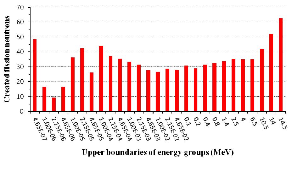
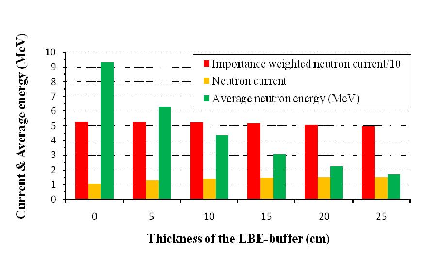
7 heating (Ågren et al., 2010). Figure 2 shows the assumed distribution function which is symmetrical in z. At a selected source point, the fusion neutrons were emitted with a fixed kinetic energy of 14.1 MeV in a flight direction which was isotropically selected. 3. Calculation results and discussion 3.1. Thickness of the buffer The first series of calculations with the fusion neutron source was devoted to a blanket design without a buffer between the first wall and the core. The results showed that this configuration would result in a first wall lifetime clearly shorter than that specified for the FTWR. The calculation results revealed that the biggest portion of the material damage was caused by the fission neutrons produced in the core and not by the fusion source neutrons. Therefore, the effect of introducing a neutron buffer was studied. In analogy to the design of the NEA-benchmark ADS, the LBE-coolant of the core was chosen as material. This idea was supported by the known fact that the lead-bismuth eutectic is a good neutron multiplier for fusion neutrons due to its high rate of n,2n-reactions (Noack et al., 2008). So, by means of calculations an optimal thickness of the buffer should be determined which, on the one hand, sufficiently shields the first wall against the fission neutrons and, on the other hand, delivers a neutron influx into the core which produces a maximal fission rate. The buffer thickness was approximately determined as follows. At first, the dependency of the neutron multiplication on the buffer thickness was studied with the help of a onedimensional model of the blanket. For these calculations the core thickness was kept constant equal to 20.5 cm. This value has been determined to give a k eff close to 0.95 for the case without buffer. A negative effect of a LBE-buffer on the neutron multiplication by the core could be that the moderation of the fusion neutrons leads to a reduction of their probability to initiate a fission reaction. To be able to consider this effect an energy dependent importance function g has been calculated on the inner core surface which then was used as a weighting function for the neutron influx into the core. In the calculation of the importance function for an energy group g, neutrons were started on this surface with outward flight directions which were selected linearly anisotropic according to p( ), where is the cosine between the flight direction and the surface normal vectors, and with a kinetic energy E n equally distributed within the energy interval g. As importance g of all simulated neutrons started in group g the number of secondary fission neutrons produced in the fission cascade initiated by the source neutron was scored. The result is shown in Fig. 3. One can see that the high-energy neutrons with E n > 6.5 MeV are essentially more advantageous for the production of fission neutrons than strongly moderated source neutrons. After this, 1d transport simulations were carried out with the geometry model comprising the fusion source in the vacuum chamber, the first wall and the buffer with varying thickness. The neutron current leaking through the outer surface of the buffer was calculated with three weighting options with the importance function g, 1 and E n. Both last variants represent the energy integrated neutron current and the average energy En of neutrons entering the core, respectively. The dependencies of these three quantities on the buffer thickness are shown in Fig. 4. The diagram illustrates the following tendencies: The neutron current flowing into the core increases up to the buffer thickness of 25 cm.
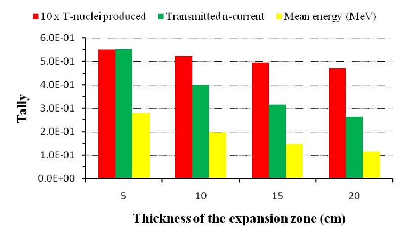
8 However, at the same time the mean energy of neutrons leaving the buffer decreases considerably indicating the stronger spectrum softening with increasing buffer thickness. As sum of both tendencies, the importance weighted neutron current shows a slightly reducing ability of a source neutron to creating fission neutrons. This result makes clear that the buffer thickness should be chosen in such a way that it sufficiently shields the first wall against the fission neutrons produced in the core. From this point of view, the buffer thickness was put to 15 cm which finally leads to a neutron load of the first wall comparable with that of the FTWR (see subsection 4.2.) Thicknesses of the expansion zone and of the core From the results of some trial criticality calculations an approximate value of the core thickness was derived. After this, calculations with special 1d-geometry models were carried out to approximately examining the impact of the expansion zone thickness on the tritium breeding rate within the 50 cm thick radial reflector. The geometry comprised only the expansion zone and the radial reflector as material zones. The core and the other inner zones were filled with perfect neutron absorber. In these calculations, neutrons were started at a point on the inner surface of the expansion zone in outward directions which were linearly anisotropic selected (quite analog as in subsection 3.1.) and with energies randomly selected according to a core averaged flux spectrum which has been estimated in a test calculation with fusion source for a system with the approximate core thickness, with the 50 cm thick radial reflector and with a guessed thickness of 5 cm for the expansion zone. The results of three quantities (tallies per started neutron) are represented in Fig. 5. The statistical errors are far below 1%. The decisive quantity is the tritium production rate. The diagram shows that it moderately drops with increasing expansion zone thickness, though the current of the neutrons flowing for the first time into the radial reflector decreases essentially steeper. The reason for this is the stronger energy moderation of these neutrons with growing zone thickness as indicated by their mean energy. Due to the fact that the cross-section of the n,t-reaction at Li-6 increases with falling neutron energy, the reduction of the neutron inflow in the radial reflector is partly compensated. The positive effect of the expansion zone is twofold: Having free space available for loading the core with more fuel if necessary and for installing absorbers or special irradiation assemblies. The expansion zone filled with LBE also acts as outer reflector of the core. Therefore, in case of falling coolant level, at first this reflector is partly removed producing a drop of the capability of the system to multiply neutrons. Concerning reactor safety, this is a positive effect (see subsection 3.3.). On the other hand, the zone thickness should not be chosen too large since this gives an unnecessary increase of volume and mass of the radial reflector. Considering the different effects, the conclusion was drawn that 15 cm should be a suitable thickness of the expansion zone. After fixing the thicknesses of the buffer and the expansion zone, criticality calculations with the 2d geometry model were carried out to find the core thickness giving an effective multiplication factor very close to Finally, its thickness was put to 21.3 cm which gave k eff = for the operation state outlined in subsection 2.1. With this thickness follows a core volume of 39.7 m 3 containing 20.8 tonnes of TRU-isotopes. Calculation results 1 The errors given for calculated values of k eff are the standard deviations.
9 presented below are not downscaled but are assumed to be valid for the case with the exact value k eff = Criticality analysis of coolant void effects In fission reactors with fast neutron fields the loss of the coolant in core regions can result in an increase of the criticality. This could occur in succession of a break in the coolant loop or of local blocking of the coolant flow through the core. Hence, one has to know which maximal value the criticality could reach in such accidents. For this reason, two series of criticality calculations were carried out for several hypothetically assumed states of the present hybrid model loaded with fresh fuel. The first calculations were carried out for several coolant levels. In the voided core regions, the cross-section sets which are given for 1800 K in Jeff-3.1 were used for the TRU- and Zr-isotopes of the fuel. The same temperature was assumed in the calculation of the Doppler-effect the result of which is presented in the following subsection. This measure implicates that the calculated criticality effects contain the void effect as well as the Doppler-effect. However, it turned out that the latter is negligibly small. The results of the calculations for different coolant levels are shown in Fig. 6 as criticality effects relative to the operation state. The standard deviations are or less. The x-coordinate indicates the coolant levels on the vertical axis of the hybrid. The lowest level means just complete voiding of the LBE-loop. From this figure one can conclude that there is no indication of a positive effect. Evidently, this is due to the strong negative effect of voiding the expansion zone and the buffer which leave the core unreflected. In the other series of calculations several configurations were calculated which could be hypothetically assumed to appear in consequence of local coolant boiling. For this purpose, in several co-axial cylindrical rings the LBE-coolant was removed and the fuel temperature increased as described above. The obtained results are shown in Fig. 7. The diagram illustrates a fact which is well known from liquid-metal cooled fast reactors, namely that coolant voiding in central parts of the core produces a positive reactivity effect. It is caused by the hardening of the neutron spectrum which yields a bigger ratio of fission neutron production rate to neutron absorption rate. With larger extension of the voided area an opposite effect starts to work the loss of a neutron-reflecting outer core region which adds a negative contribution to the total effect. Therefore, the largest effect appears in case 3 and not for the complete voiding. The calculation results show that any local boiling will indeed result in a positive reactivity effect. However, it remains limited to low tolerable values an effect of larger than 0.02 seems to be very unlikely. Obviously, this limitation of the reactivity effect is due to the thin radial extension of the core. The favorable fact that the blanket remains in deep sub-criticality even in case of maximal criticality increase should be especially pointed out. Moreover, this fact suggests that an increase of the nominal criticality up to k eff =0.97 could be possible without noticeable loss of reactor safety Reactivity temperature coefficients Concerning reactor safety of the blanket not only hypothetical states as considered in the previous subsection are of importance but also temperature effects which cause changes of the criticality. So, excursions of the fission power P fis could lead to temperature increases which then could result in partial disintegration of fuel rods. For the present hybrid one can expect two main components of the total temperature effect: The so-called Doppler-effect which is the response of the criticality to changes of the fuel temperature. The coolant temperature effect which acts via the coolant density.
10 It is known that the Doppler-effect is very small for fuel compositions which are free of fertile isotopes. Since the nuclear effect grows with increasing temperature, a criticality calculation was carried out where we used for the TRU- and Zr-isotopes of the fuel the crosssection sets for the highest temperature of 1800 K available in the library JEFF-3.1. One can expect that the bigger effect can be calculated with higher statistical precision. In this way, the result k eff = relative to the nominal operation state was obtained. As expected, concerning reactor safety the effect is favorable, i.e. negative, and its magnitude is small a fact which is due to the very small amount of U-238 in the fuel. Generally, in reactor dynamic calculations so-called reactivity temperature coefficients are used. The reactivity of a fission system relates to its criticality according to: ρ k 1 eff. (1) keff The reactivity temperature coefficient is C T = / T. Assuming linear dependency (T) one can approximately calculate the reactivity coefficient from the criticalities in two states with temperatures T 1 and T 2 according to: C T Δk eff 1. (2) k k ΔT eff,1 eff,2 In this way, one obtains C T,Doppler /K 30%. The absolute value is one order of magnitude bigger than calculated for the FTWR (Hoffman and Stacey, 2002). The reason for this could consist in the fact that the fuel of the FTWR has a higher TRU to Zr ratio which produces a harder neutron flux spectrum and so reduces the Doppler-effect. In order to achiev a higher statistical precision, attempts were also made to calculate the Doppler-effect by means of the differential perturbation method offered by MCNP5. However, a calculation regime, which delivered reasonable results with acceptable precision, could not be established. By means of the perturbation option two results of the coolant temperature density effect (CTD) were derived. This effect consists in a reactivity change due to the density variation of the LBE-coolant caused by a variation of its temperature. Assuming an increase of the LBEtemperature from 700 to 1000 K its density decreases from to 9.78 g/cm 3. The total effect was split in two components: density variation within the core only and density variation in the buffer as well as in the expansion zone. The associated temperature coefficients C T,CTD (1/K) were derived from the calculated reactivity effects: Core Buffer and expansion zone Total effect The results qualitatively harmonize with those obtained for the corresponding void effects. However, the coefficient of the total effect is substantially bigger than the value quoted for the FTWR (Hoffman and Stacey, 2002). The impacts of the calculated coefficients on the dynamical behavior of a power hybrid have still to be studied Results of calculations with the fusion neutron source Specific integral parameters Integral parameters which are important for the fusion-fission hybrid as a whole were either derived from data given in the list of certain events that occurred during the neutron
11 transport, which is delivered by default with the output of a MCNP-run, or estimated as regular tallies. The results are given in Table 1. By means of calculated primary data and of the effective multiplication factor k eff further secondary parameters can be derived. The quantity: M eff keff (3) (1 k ) eff represents the fission neutron multiplication factor per fission source neutron in the framework of the static reactor eigenvalue equation. Equations (1) and (3) give the relationship M eff =-1/. For the designed hybrid it follows M eff =19. The ADS-community introduced the so called φ * -parameter as ratio between both neutron multiplication factors: M S. (4) M eff It characterizes the relation between external neutron source and fission blanket (Gandini and Salvatores, 2002). In the present case one obtains φ * = Of big practical importance is the amplification ratio of the power P fus delivered from the fusion driver to the total power released in the whole blanket P tot. Because of exothermic neutron reactions other than fission, the power P tot is generally a few percents bigger than the fission power P fis. Considering that one source neutron is connected with the energy release of E fus =17.6 MeV from the fusion reaction one can define power amplification factors (PAF) by means of h fis and h tot : PAF fis h h fis tot, PAFtot. (5) E fus E fus So, one obtains for the mirror hybrid PAF fis =86.0 and PAF tot =89.2. These amplification factors give the relationships: P fis PAF P, P PAF P. (6) fis fus tot tot fus The power amplification factor takes the decisive part concerning the power performance of the whole fusion-fission hybrid (see subsection 4.4.). It is necessary to point out to the following fact. All those parameters which are normalized per fusion source neutron contain the neutron multiplication by the cascade of fission reactions and therefore, they scale approximately in proportion to M eff. Hence, they vary with the burn-up during an operation cycle. So, the relationship: PAF (7) fis M eff is valid for the present mirror hybrid (Ågren et al., 2010). Of certain interest is the averaged neutron current per fusion source neutron consisting of those neutrons entering the core for the first time (see also subsection 3.1.). A special calculation gave the following results for the entrances through the different core surfaces: Through the inner cylindrical core surface 1.37 Through both front faces
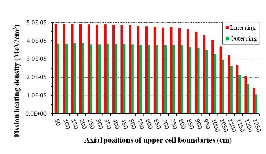
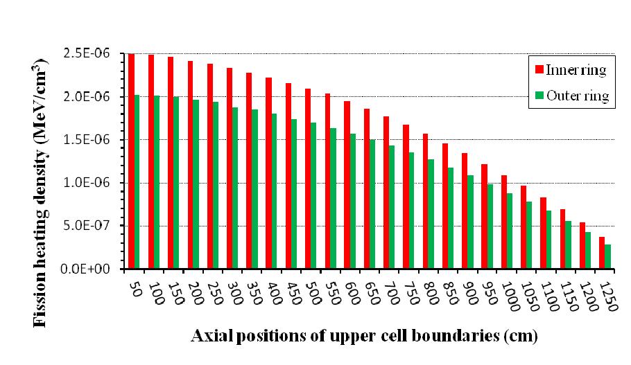
12 Through the outer cylindrical core surface The total current of 1.37 results from the n,2n-reactions which are initiated by the fusion neutrons especially in collisions with the nuclei of lead and bismuth. For the proposed concept SABR of a tokamak based fusion-fission hybrid with geometry similar to the FTWR the authors found out that 39% of the fusion source neutrons would reach the core (Stacey et al., 2008). The difference between both figures points out the advantageous geometrical arrangement of the neutron source and the fission core in case of the mirror hybrid Space dependency of the fission power generation By means of the FMESH-tally option axial and radial dependencies of several neutron flux integrals were estimated. The axial extension of the mesh cells was z=50 cm. In radial direction the core was divided in 7 equally thick cells. Figure 8 shows the axial dependencies of the fission energy deposition density (fission heating) per fusion source neutron within the inner and outer rings. In the diagram the cell averaged values per source fusion neutron are applied. The statistical errors are less than 1.6%. Figure 9 shows the fission heating density per fission source neutron obtained from the corresponding criticality calculation. Here, the statistical errors are less than 1%. Both figures make clear an important difference: in case of the hybrid the fission heating exhibits a flat plateau up to about z=850 cm whereas in case of the static reactor equation such a plateau does not appear. The source of fission neutrons is more strongly accumulated around the centre and continuously drops off in the directions of the front faces of the core. Evidently, the difference is the result of the axial structure of the fusion neutron source. Regarding the burn-up of fuel and its transmutation this characteristic of the designed hybrid is a favorable one. Figure 10 illustrates the radial dependencies of the fission heating in both cases. In order to obtain a common scaling for the diagram the heating of the fission neutrons was multiplied by M eff. One can see that both radial dependencies are quite similar and show only a weak decrease in outward direction. Evidently, this is a result of the narrow core and the good neutron reflection by the LBE of the buffer and the expansion zone. The radial flatness of the fission heating is also a favorable peculiarity of the present hybrid design Neutron flux spectrum and microscopic fission rates Concerning burn-up and transmutation of the fuel not only the amplitude but also the spectrum of the neutron flux is of importance. The diagram of Fig. 11 shows the energy group fluxes (neutron flux integrated over energy intervals) per fusion source neutron (their sums were normalized to 1) averaged over three volumes over the entire core, the inner ring and the outer ring where both have a thickness of 5 cm. One can identify noticeable deviations only in the low energy range E n < 1 kev and in the high-energy range E n > 1 MeV although they are very small. Evidently, there are still some fusion neutrons in the inner ring but no in the outer one. Likewise, one can see a larger fraction of neutrons which are stronger moderated by the LBE-buffer. Altogether one can conclude that the neutron flux spectrum only very weakly varies within the core. It is mainly determined by its material composition and the impact from the outside remains negligibly small. Hence, one can expect that almost equal burn-up and transmutation characteristics are valid within the whole core volume. Concerning the incineration of long-lived fissionable fuel isotopes, fission is the ultimate nuclear reaction. Thus, it is of particular interest to know which fission rate the neutron spectrum of the core produces with the nuclei of a single isotope. The diagram of Fig. 12 shows the calculated microscopic fission rates for isotopes contained in the fuel of the present hybrid. The represented quantity is the averaged number of fission reactions produced per fusion source neutron and per nucleus of the considered isotope. The statistical errors are around 1%. The diagram clearly shows that the well fissionable isotopes like U-235, Pu-239,
13 Pu-241, Am-242m, Cm-243 and Cm-242 have the highest fission rates, whereas the hardly fissionable isotopes give fission rates which are about one order of magnitude less. In a harder neutron spectrum the latter isotopes would give higher fission rates. By means of these calculation results and of the fractions of delayed fission neutrons for each isotope one obtains for the composition of the spent fuel an averaged effective delayed neutron fraction of β eff = This parameter is of great importance concerning the nuclear safety of the blanket Neutron load of the first wall A serious technological problem of fusion power reactor concepts which has to be solved is the deterioration of the first wall caused by the high-energy neutron irradiation. In this case the main contribution comes from the fusion source neutrons striking directly the wall. Depending on the design, the situation can be another in case of fusion-fission hybrids. Here, the neutron load resulting from the fission neutrons produced in the core must be considered too. It was already explained in subsection 3.1., that just for better shielding against the fission neutrons a buffer with a thickness of 15 cm filled with LBE had to be introduced between the first wall and the core. In the following, the neutron load of the first wall will be analyzed and in section 4., the obtained results will be transferred to hybrid options operating with nominal criticalities k eff <0.95 or k eff <0.97 and generating thermal fission powers of 3 GW th or 1.5 GW th. Usually, the neutron load of fusion devices is characterized by two parameters. These are: The 14 MeV neutron wall load (MW/m 2 ). The radiation damage of the first wall material measured in DPA (displacements per atom). In the range of the neutron source, the contribution of neutrons to the surface heat load of the first wall is unsubstantial (see subsection 4.2.). At first, both quantities were calculated for the idealized case of irradiation of the first wall by the fusion source neutrons alone, i.e. all other material zones of the model were removed. To really find the maximum of the DPA-rate in the calculations, the wall was divided into two rings of equal thickness 1.5 cm. Figure 13 shows both the calculated energy current transported by fusion source neutrons through the axial intervals of the inner wall surface which was estimated using the *F1-tally of MCNP5 and the cell averaged DPA-rates in the outer ring of the wall. The statistical errors are far below 1%. Both profiles reflect a little bit smeared the profile of the source distribution (see subsection 2.2.). The total energy current is MeV per source neutron. The difference to the source energy of 14.1 MeV is lost through the front ends of the vacuum chamber. This small amount of the direct loss of fusion neutrons is a consequence of the long stretched geometry of the blanket with relatively tight holes at the ends. The DPA-rates in the inner wall ring turn out to be about 30% larger than those in the outer ring. However, further below it will become clear that the maximum of the total DPA-rate appears in the outer ring. By means of further calculations with certain geometry models the DPA-rates produced in the cells of the outer wall ring were finally split up in accordance with following sets of neutrons: Fusion neutrons coming directly from the source. Fusion neutrons which were backscattered by buffer and/or axial reflector. Fission neutrons produced in the core. Figure 14 shows the calculation results per fusion source neutron. The statistical errors are less than 2%. One can see that the fission neutrons give the by far biggest contribution. This is the reason why the maximal DPA-rate appears in the outer ring of the first wall. Here, it should be pointed out that the relations shown in the diagram are valid for the defined state of
14 the system. In a power hybrid they will change with the burn-up of the fuel (see subsection 4.2.). 4. Extrapolations to power hybrids 4.1. Cycle length and the required fusion powers The first version of the FTWR has been proposed with a fission power output of 3 GW th. In order to let the designed mirror hybrid generate the same amount of fission power, the required fusion power can be calculated with the help of the power amplification factor PAF fis specified in subsection However, the obtained value of fusion power is valid only in the state when the fuel is of original composition, i.e. if k eff =0.95 at the beginning of an operation cycle (BOC). In case of a power hybrid, the burn-up of the fuel results in a drop of its criticality k eff which reduces its power amplification factor in accordance with Eqs. (3) and (7). Hence, in order to keep the fission power output constant the power of the fusion neutron source must be continuously increased up to the end of the cycle (EOC). This fusion power swing between BOC and EOC grows with the cycle length. Thus, to hold the fusion power minimal a shorter cycle length is advantageous. For this reason, the cycle lengths of all hybrid options considered in the following were fixed to 311 effective full power days (EFPD) which is just half of the FTWR-cycle. To be able to calculate the maximal fusion power required at EOC, one has to know the criticality of the blanket at this moment. Because own burn-up calculations were not yet carried out, the EOC-criticality was determined by linear interpolation between the burn-up data given for the FTWR which led to k eff =0.90. This approach can be considered as an acceptable approximation since the actinide compositions of both fuels are identical at BOC. The power amplification factor PAF fis at EOC can now be calculated according to Eq. (7). The fusion powers obtained in this way for the mirror hybrid are given in Table 2. Because of its analogy to the FTWR, this option subsequently will be called analog mirror hybrid. In addition, in order to assess other options with respect to further reduction of the fusion power the consequences of two measures were considered. The numerical results are given in Table 2. Reduction of the fission power output of the hybrid: this trivial way does not require any modifications of the blanket. As an example, the results of a hybrid generating 1.5 GW th are given. In the calculation of the fusion power at EOC it was considered that the burn-up rate of the fuel now is reduced by a factor two and correspondingly the criticality drop-off over an operation cycle too. Increase of the nominal criticality at BOC to k eff =0.97: calculation results show that for achieving this criticality with the same core composition its radial thickness must be extended about 1 cm only. The TRU-mass would then amount to 21.9 tonnes. Due to the higher neutron multiplication in the core, the power amplification factor at BOC would be PAF fis = The fusion power was approximately calculated by the same approach as used for the analog hybrid. Both options superimposed: the required fusion power was also calculated for a hybrid operated with nominal criticality of k eff =0.97 and generating 1.5 GW th. From today s point of view, at least the option with reduced power output and increased nominal criticality seems to be achievable for mirror plasma devices in near future. Assuming for the plasma-q defined by Q p =P fus /P heat a value of Q p = 0.15, which is assessed to be realistic for mirrors, it follows that a power P heat of 70 to 130 MW has to be launched into the plasma. This should be realizable by ion cyclotron resonance heating. So, this version could be considered as a near-term option of a mirror driven hybrid. Its neutron load of the first wall
15 and the tritium breeding ratio will be estimated in the subsequent subsections. Likewise, a rough estimate of its overall energy performance will be made Heat load and the accumulated neutron load of the first wall Concerning the heat load of the first wall in the area of the confinement region, the analog hybrid identified in the previous subsection at the moment EOC represents the worst case. Taking P fus from Table 2 and Q p =0.15 as before one obtains P heat =494 MW, a figure which seems to be non-achievable. Nevertheless, supposing typical 5% radial losses then the maximal heat load of the first wall would result in 0.2 MW/m 2 which is clearly below critical values. These are assumed to be substantially greater than 1 MW/m 2. For the FTWR a value of 0.34 MW/m 2 has been quoted. This fact makes clear that the plasma heat load does not represent any problem for the first wall in the range of the confinement region. In addition to the heat of about 25 MW supplied by the plasma, the power deposited from all types of neutrons was calculated to 5.1 MW only. Since the neutron energy is rather homogeneously deposited over the wall thickness, the neutron heating does not change the picture essentially. In mirror devices the problem of the deposition of the plasma heat concentrates on the plasma dumps installed in two tanks which are attached to the ends of the cylindrical vacuum chamber. Plane plasma dump plates with a radius of 4 meters or alternatively with smaller radius but with W-shaped surfaces would result in averaged heat loads of 5 MW/m 2 and 1.3 MW/m 2 for the analog and the near-term mirror options, respectively. These values are clearly below the permissible limit of 10 MW/m 2 which is assumed for the divertor of the ITERproject. The DPA-rate produced in the first wall over the range of the confinement region varies during an operation cycle. The fraction of fission neutrons is proportional to the fission power of the hybrid and hence, it is steady-state. On the other hand, the fraction of the fusion neutrons grows with the rising fusion power. One can derive an approximate estimate of the DPA accumulated during an operation cycle. Considering the fusion powers given in Table 2 for the analog hybrid, one obtains the macroscopic DPA-rate of the fission neutrons and the total rates from all neutrons at BOC and EOC which are shown in Fig. 15 from the calculation results presented in subsection Regarding the steady contribution of the fission neutrons, it is assumed that the space-dependency of the fission source remains unchanged that calculated for the state BOC. Then, assuming a linear drop of k eff between BOC and EOC and considering that the fusion source intensity S grows with 1/M eff one can calculate the accumulated number of DPA. The results are presented in Fig. 16. One can see that the maximum appears in the interval 750 < z (cm) < 900. At the maximum, the first wall accumulates 12.3 DPA during a 311 EFPD-cycle. This is close to the value quoted for the FTWR: 21 DPA during a 623 EFPD-cycle. Assuming that the HT-9 steel can withstand an accumulated DPA of about , as predicted for DEMO, the first wall of the analog hybrid would have a lifetime of cycles. It is of interest to inspect the consequences of the same measures considered in the previous subsection on the driver power now on the maximal DPA per cycle. In the same way as for the analog hybrid before, one can calculate the DPA for the modified hybrid versions too where the data of Table 2 have to be used. The increase of the nominal criticality of the analog hybrid results in a decrease of the DPA but merely by about 7%. This is the consequence of the reduced fusion power. Because the DPA-fracture caused by fission neutrons is dominating, the reduction of the fission power is substantially more efficient. So, for the first wall of the near-term mirror hybrid both measures result in a maximal DPA-value per cycle of 5.7 only. Thus, its lifetime is considerably extended up to the range between 26 and 35 cycles.
16 4.3. Tritium reproduction An unconditional design objective of the present hybrid model was its tritium selfsufficiency. It should be reached under the more complicated condition to use the radial reflector for tritium breeding and not the core itself. For the analog mirror hybrid at BOC a tritium breeding ratio of TBR=2.95 was calculated (see Table 1). Because the fusion neutron source intensity rises during the cycle, really the tritium balance per cycle must be considered. The amount of tritium produced is determined by the neutron field in the core, i.e. approximately by the fission power which is held steady-state. On the other hand, the tritium consumption grows with the fusion source intensity. The same approach as used in subsection 4.2. for the calculation of the neutron wall load leads finally to the tritium breeding ratio per cycle TBR cycle =1.91. So, the tritium production essentially surmounts self-sufficiency and thus would make possible a reduction of the Li-6 enrichment. The tritium reproduction balances of the modified versions of the mirror hybrid can easily be estimated by analog extrapolations and assuming that the tritium production in the radial reflector is proportional to the fission power and does not depend on the fusion power. The obtained results show that both the increase of the nominal criticality and the decrease of the fission power rise the tritium breeding ratio per cycle: increasing the nominal criticality of the analog hybrid to k eff =0.97 results in TBR cycle =2.65 and the additional power decrease for the near-term hybrid results in TBR cycle =3.60. In the latter case, the Li-6 enrichment could be substantially reduced Total power performance The engineering Q Q e of a fusion-fission hybrid is defined as ratio of the gross electric power produced to the gross electric power inputted for operating the whole device (Stacey et al., 2002) and can be approximately expressed in our case by: Q e P P prod oper η th PAF P fis P fis fis ( Q p ) (1 ) PAF icr Q p P pump fis P magn. (8) In this equation are: th the thermal-to-electrical conversion efficiency assumed to be 0.4, icr the electric efficiency of the ion cyclotron resonance heating assumed to be 0.7, P pump the sum of all coolant pumping powers, P magn the power required for cooling the magnetic coils. For the main component of the produced power the fission power P fis is approximately inserted instead of P tot. The full dependency of Q e on the criticality of the hybrid is contained in the fission power amplification factor PAF fis according to Eqs. (3) and (7). The power amplification of the FTWR has been estimated to be merely Q e 1. Later, the improved concept FTWR-SC has been devised. For this version Q e =4.9 has been quoted (Mauer et al., 2004). Analogously as for the neutron load and for the tritium breeding, the appropriate characteristic for the energetic performance of a cycle-wise operated hybrid is the ratio of the amounts of energy produced and consumed during a cycle: cycle E cycle prod Qe. (9) E cycle oper
17 In order to calculate this ratio one has to specify the power components P pump and P magn. In this stage of design, these quantities were not yet analyzed. However, rough estimates can be made with the help of the data quoted for the FTWR and the FTWR-SC as follows. Superconducting magnets are foreseen for the present mirror hybrids (Hagnestål et al. 2010). In case of the FTWR-SC, the cooling power for the magnets proved to be negligibly small (Stacey, 2010). The same fact is supposed for the mirror hybrids. Moreover, it seems reasonable in a preliminary estimate to assume that the sum of pumping powers required for all coolant loops should be close to the value specified for the FTWR, P pump =131 MW el. With both assumptions and with Q p =0.15 one can calculate both energy terms of Eq. (9). So, for the cycle analog mirror hybrid one obtains Q e Supposing for the near-term option that the pumping power amounts just to half of the FTWR-value because the produced power is only cycle the half, then one obtains Q e For the same case but with the improved value Q p =0.3 cycle evenq 4. 5 follows. e 5. Summary and conclusions By means of neutron transport calculations a cylindrical model of a mirror fusion-fission hybrid was devised. The calculations were carried out with the Monte Carlo code MCNP5 and with nuclear data from the Evaluated Nuclear Data Library JEFF-3.1. According to the calculation results, the model fulfills all demands listed in Section 1. In more detail, the most important features can be summarized as follows: 1) As opposed to the FTWR, the system has two coolant loops an inner loop with lead-bismuth eutectic cooling the first wall and the core and an outer loop with the eutectic Li17Pb83 which cools the radial reflector. Even in this case, the tritium breeding in the outer loop turned out to be essentially higher than necessary for self-sufficiency. The transfer of the T-breeding in the radial reflector mainly results in two advantages for the core: The absence of the Li-6 results in a better neutron economy. Thus, the dispersed fuel (TRU-10Zr)/Zr can be used just in the composition as planned for the HYPER-project. As consequence, the TRU-content of the fresh fuel loading was reduced to 20.8 tonnes. Concerning nuclear safety, the use of LBE instead of Li17Pb83 in the core results in lowered reactivity gains in cases of coolant temperature rise or of local coolant boiling. In this way, power peaks caused by accidents or operation malfunctions remain lower. 2) It turned out that the first wall should be shielded against the fission neutrons produced in the core to get a longer lifetime of the wall. For this purpose, the core was shifted outwardly and a buffer filled with LBE of the inner coolant loop was inserted between the core and the first wall. The radial thickness of the buffer was chosen to diminish the maximum neutron load at least close to the value specified for the FTWR. Assuming that the HT-9 steel can withstand DPA as supposed for DEMO, the lifetime of the first wall would amount to cycles of 311 EFPDs for the analog mirror hybrid. 3) In addition, another zone filled with the LBE of the inner coolant loop was inserted between the core and the radial reflector. The reason for this was twofold: first, to leave free space for core expansion which could be necessary for core loadings with fuels of other TRU-composition and for installing absorbers or irradiation assemblies. Second, in case of an accident leading to loss of the coolant from the inner loop the voiding of this zone produces a strong drop of the criticality. Due to
18 this fact, no increase of criticality was observed for different height levels of the LBE-coolant. 4) From liquid metal cooled fast reactors it is known that strong criticality increases can appear in accident situations leading to local boiling of the coolant in internal regions of the core. Since the geometry of the present model is completely different from that of such a reactor, this result must not be transferred ad hoc to the mirror hybrid. Therefore, it was of great interest to obtain estimates for several selected states. In fact, voiding of the LBE-coolant in central core regions results in an increase of the criticality. However, the maximum increase of criticality that was found was clearly less than 2%. This result shows that such events leave the fission blanket in a deep subcritical state with high reliability. Moreover, this result suggests that an operation with a nominal criticality of k eff =0.97 would also have a sufficient safety margin. 5) For the power dynamics of the hybrid so-called reactivity temperature coefficients are of special importance. The coefficients of two main effects were calculated. As expected, the Doppler-coefficient of the fuel is negative and has a small absolute value: /K 30%. The coefficient of the LBE-coolant temperature density effect was calculated to /K 2%. The effects of these values on the dynamics of power transients still have to be studied in detail. 6) Several specific integral parameters of the analog mirror hybrid were calculated for the nominal state at the beginning of a cycle. The neutron multiplication factor of a fusion neutron is The neutron multiplication by fission reactions implies an amplification factor from fission to fusion power PAF fis =86.0 and the φ * -parameter of the hybrid amounts to At this moment of operation, the tritium breeding ratio is ) Because of the special axial dependency of the neutron emission density which is representative for a mirror with sloshing high-energy ions, the generated fission power density shows a rather flat profile up to the distance from the centre of about 8.5 m. Quite similarly, its radial dependency turns out to be rather flat which is evidently caused by the small radial core thickness. Both features are favorable regarding power generation and incineration of TRU-isotopes. 8) In order to obtain reduced fusion power requirements for the mirror, the length of an operation cycle was put to 311 full power days which corresponds to half of a FTWR-cycle. Burn-up calculations for the mirror hybrid have not yet been carried out. Referring to burn-up data given for the FTWR, one can estimate that this mirror hybrid analog to the FTWR reaches the criticality k eff =0.90 at the end of a cycle. Then, considering the scaling of the power amplification factor according to Eq. (7) it can be shown that the steady generation of 3 GW th of fission power over the whole cycle requires the supply of fusion power in the range between ~35 and ~75 MW. 9) With respect to further reduction of the required fusion power, the consequences of increasing the nominal criticality to k eff =0.97 and of decreasing the fission power to 1.5 GW th on the main parameters were approximately estimated. From the results obtained a hybrid version was identified which could be considered as a near-term option. It requires a fusion power between 11 and 20 MW only. 10) Compared to the analog mirror hybrid, the near-term option gives substantial improvements: the lifetime of the first wall is extended to cycles and the cycle integrated tritium breeding ratio increased from 1.9 to 3.6. With the reference to data quoted for the FTWR and the FTWR-SC rough estimates of cycle related energy amplification factors Q e cycle for the different mirror hybrids were made. So, for the analog mirror hybrid Q e cycle =2.1 and for the near-term option Q e cycle =3.1
19 were obtained. These values point out a potential for electric power production even with a plasma-q of Q p =0.15 only. Increasing this parameter to Q p =0.3 would actually result in Q e cycle =4.5. However, one has to consider that both latter options are accompanied by the drawbacks of half of the rates of power production and TRU-incineration delivered by the analog mirror hybrid. 11) In addition to the dependencies of k eff on the burn-up, future burn-up calculations for the power hybrids should address the macroscopic burning and transmutation rates of the individual transuranium isotopes. For the FTWR these results are given in Ref. (Stacey et al., 2002). Acknowledgement The authors are grateful for financial support from the Swedish Institute. References Abagjan, L.P., et al., Group constants for calculations of reactors and shielding, Moscow, Energoisdat. Ågren, O., Savenko, N., Theoretical study of increased electron temperature in mirror machines by tuned ion cyclotron resonance cycles, Phys. Plasmas 12, ID Ågren, O., et al., Studies of a Straight Field Line Mirror with emphasis on fusionfission hybrids, Fusion Science and Technology 57, 326. Bell, G.I., Glasstone, S., Nuclear Reactor Theory, Van Nostrand Reinhold Company. Bethe, H.A., The fusion hybrid, Physics Today 44. Bowman, C.D. et al., Nuclear energy generation and waste transmutation using an accelerator-driven intense thermal neutron source, Nuclear Instr. Methods Phys. Res. A320, Issues 1-2, 336. Cheng, E.T., Cerbone, R.J., Prospect of Nuclear Waste Transmutation and Power Production in Fusion Reactors, Fusion Technology 30, Fusion Network, Gandini, A., Salvatores, M., The physics of subcritical multiplying systems, J. Nucl. Sci. Technol. 39, 673. Hagnestål, A., et al., A study on theoretical field and coil design for a single cell minimum-b mirror-based fusion-fission reactor, submitted to Fusion Engineering and Design. Hoffman, E.A., Stacey, W.M., Nuclear and Fuel Cycle Analysis for a Fusion Transmutation of Waste Reactor, Fusion Engineering and Design 63-64, 87. Mauer, A.N., et al., A Superconducting Tokamak Fusion Transmutation of Waste Reactor, Fusion Science and Technology 45, 55. Moiseenko, V.E., Noack, K., Ågren, O., Stellarator-mirror based fusion driven fission reactor, J. Fusion Energy 29, 65. Noack, K., et al., The GDT as neutron source in a subcritical system for transmutation, Trans. of Fusion Sci. and Technol. 51, 65. Noack, K., et al., The GDT-based fusion neutron source as driver of a minor actinides burner, Ann. Nucl. Energy 35, OECD NEA, pdf. OECD NEA Data Bank, NEA-document NEA/NSC/DOC(2001)13. OECD NEA Data Bank, NEA-document NEA/NSC/DOC(2006)18. ORNL, Fusion materials, Park, W.S., et al., Design Progress of HYPER System, IAEA-Tecdoc 1348, 195.
20 Plukiene, R. et al., Fusion-fission hybrid system for nuclear waste transmutation (II): From the burn-up optimization to the tests of different data libraries, Progress in Nuclear Energy 48, 247. Ridikas, D. et al., Fusion-fission hybrid system for nuclear waste transmutation (I): Characterization of the system and burn-up calculations, Progress in Nuclear Energy 48, 235. Rubbia, C., A High Gain Energy Amplifier Operated with Fast Neutrons, AIP Conference Proceedings 346, International Conference on Accelerator-Driven Transmutation Technologies and Applications, Las Vegas. Stacey, W.M. et al., A Fusion Transmutation of Waste Reactor, Fusion Science and Technology 41, 116. Stacey, W.M., et al., A Subcritical, Helium Cooled Fast Reactor for the Transmutation of Spent Nuclear Fuel, Nuclear Technology 156, 99. Stacey, W.M., et al., A TRU-Zr Metal-Fuel Sodium-Cooled Fast Subcritical Advanced Burner Reactor, Nuclear Technology 162, 53. Stacey, W.M., Personal communication. Taczanowski, St., Domanska, G., Cetnar, J., Fusion-driven transmutation of nuclear waste a misconception or an incentive for promotion of fusion energy?, Fusion Engineering and Design 41, 455. X-5 Monte Carlo Team, MCNP A General Monte Carlo N-Particle Transport Code, Version 5 (Rev. 2005), Los Alamos report LA-CP Übeyli, M., Potential use of molten salt bearing plutonium fluorides in a magnetic fusion energy reactor, Ann. Nucl. Energy 35, 1087.
21 Figure 1 (revised): Zoom area 1.8 m Vacuum chamber Blanket End zone 0.5 m 26 m Zoom area Radial reflector Core expansion zone (LBE) Fission blanket (core) Buffer (LBE) First wall Axial reflector r=1.943 m r=1.443 m r=1.293 m r=1.08 m r=0.93 m r=0.9 m
22 Figure 2:
23 Figure 3:
24 Figure 4:
25 Figure 5:
26 Figure 6:
27 Figure 7:
28 Figure 8:
29 Figure 9:

30 Figure 10:

31 Figure 11:
32 Figure 12:
33 Figure 13:

34 Figure 14:

35 Figure 15:

36 Figure 16:
Adaptation of Pb-Bi Cooled, Metal Fuel Subcritical Reactor for Use with a Tokamak Fusion Neutron Source
 Adaptation of Pb-Bi Cooled, Metal Fuel Subcritical Reactor for Use with a Tokamak Fusion Neutron Source E. Hoffman, W. Stacey, G. Kessler, D. Ulevich, J. Mandrekas, A. Mauer, C. Kirby, D. Stopp, J. Noble
Transmutation of Minor Actinides in a Spherical
 1 Transmutation of Minor Actinides in a Spherical Torus Tokamak Fusion Reactor Feng Kaiming Zhang Guoshu Fusion energy will be a long-term energy source. Great efforts have been devoted to fusion research
Fusion/transmutation reactor studies based on the spherical torus concept
 FT/P1-7, FEC 2004 Fusion/transmutation reactor studies based on the spherical torus concept K.M. Feng, J.H. Huang, B.Q. Deng, G.S. Zhang, G. Hu, Z.X. Li, X.Y. Wang, T. Yuan, Z. Chen Southwestern Institute
A SUPERCONDUCTING TOKAMAK FUSION TRANSMUTATION OF WASTE REACTOR
 A SUPERCONDUCTING TOKAMAK FUSION TRANSMUTATION OF WASTE REACTOR A.N. Mauer, W.M. Stacey, J. Mandrekas and E.A. Hoffman Fusion Research Center Georgia Institute of Technology Atlanta, GA 30332 1. INTRODUCTION
3.12 Development of Burn-up Calculation System for Fusion-Fission Hybrid Reactor
 3.12 Development of Burn-up Calculation System for Fusion-Fission Hybrid Reactor M. Matsunaka, S. Shido, K. Kondo, H. Miyamaru, I. Murata Division of Electrical, Electronic and Information Engineering,
Progress in Conceptual Research on Fusion Fission Hybrid Reactor for Energy (FFHR-E)
") Progress in Conceptual Research on Fusion Fission Hybrid Reactor for Energy (FFHR-E) Xue-Ming Shi Xian-Jue Peng Institute of Applied Physics and Computational Mathematics(IAPCM), BeiJing, China December
Progress in Conceptual Research on Fusion Fission Hybrid Reactor for Energy (FFHR-E) Xue-Ming Shi Xian-Jue Peng Institute of Applied Physics and Computational Mathematics(IAPCM), BeiJing, China December
USA HTR NEUTRONIC CHARACTERIZATION OF THE SAFARI-1 MATERIAL TESTING REACTOR
 Proceedings of HTR2008 4 th International Topical Meeting on High Temperature Reactors September 28-October 1, 2008, Washington, D.C, USA HTR2008-58155 NEUTRONIC CHARACTERIZATION OF THE SAFARI-1 MATERIAL
MA/LLFP Transmutation Experiment Options in the Future Monju Core
 MA/LLFP Transmutation Experiment Options in the Future Monju Core Akihiro KITANO 1, Hiroshi NISHI 1*, Junichi ISHIBASHI 1 and Mitsuaki YAMAOKA 2 1 International Cooperation and Technology Development Center,
Progress in Conceptual Research on Fusion Fission Hybrid Reactor for Energy
 Progress in Conceptual Research on Fusion Fission Hybrid Reactor for Energy Xueming Shi 1, Xi Wang, Xianjue Peng 1) Institute of Applied Physics and Computational Mathematics Corresponding author: sxm_shi@iapcm.ac.cn
The GDT-based fusion neutron source as a driver of subcritical nuclear fuel systems
 The GDT-based fusion neutron source as a driver of subcritical nuclear fuel systems Presented by A.A.Ivanov Budker Institute, FZD Rossendorf, Joint Institute for Nuclear,, VNIITF, Snejinsk Layout of the
Fuel cycle studies on minor actinide transmutation in Generation IV fast reactors
 Fuel cycle studies on minor actinide transmutation in Generation IV fast reactors M. Halász, M. Szieberth, S. Fehér Budapest University of Technology and Economics, Institute of Nuclear Techniques Contents
Available online at ScienceDirect. Energy Procedia 71 (2015 )
") Available online at www.sciencedirect.com ScienceDirect Energy Procedia 71 (2015 ) 97 105 The Fourth International Symposium on Innovative Nuclear Energy Systems, INES-4 High-Safety Fast Reactor Core Concepts
Available online at www.sciencedirect.com ScienceDirect Energy Procedia 71 (2015 ) 97 105 The Fourth International Symposium on Innovative Nuclear Energy Systems, INES-4 High-Safety Fast Reactor Core Concepts
REACTOR PHYSICS ASPECTS OF PLUTONIUM RECYCLING IN PWRs
 REACTOR PHYSICS ASPECTS OF PLUTONIUM RECYCLING IN s Present address: J.L. Kloosterman Interfaculty Reactor Institute Delft University of Technology Mekelweg 15, NL-2629 JB Delft, the Netherlands Fax: ++31
TRANSMUTATION PERFORMANCE OF MOLTEN SALT VERSUS SOLID FUEL REACTORS (DRAFT)
") 15 th International Conference on Nuclear Engineering Nagoya, Japan, April 22-26, 2007 ICONE15-10515 TRANSMUTATION PERFORMANCE OF MOLTEN SALT VERSUS SOLID FUEL REACTORS (DRAFT) Björn Becker University
15 th International Conference on Nuclear Engineering Nagoya, Japan, April 22-26, 2007 ICONE15-10515 TRANSMUTATION PERFORMANCE OF MOLTEN SALT VERSUS SOLID FUEL REACTORS (DRAFT) Björn Becker University
A SAFETY AND DYNAMICS ANALYSIS OF THE SUBCRITICAL ADVANCED BURNER REACTOR: SABR
 A SAFETY AND DYNAMICS ANALYSIS OF THE SUBCRITICAL ADVANCED BURNER REACTOR: SABR A Thesis Presented to The Academic Faculty by Tyler S. Sumner In Partial Fulfillment of the Requirements for the Degree Master
Lesson 14: Reactivity Variations and Control
 Lesson 14: Reactivity Variations and Control Reactivity Variations External, Internal Short-term Variations Reactivity Feedbacks Reactivity Coefficients and Safety Medium-term Variations Xe 135 Poisoning
NUCLEAR MISSIONS FOR FUSION (TRANSMUTATION, FISSILE BREEDING & Pu DISPOSITION) W. M. Stacey June 18, 2003
 W. M. Stacey June 18, 2003") NUCLEAR MISSIONS FOR FUSION (TRANSMUTATION, FISSILE BREEDING & Pu DISPOSITION) W. M. Stacey June 18, 2003 SUMMARY There are potential applications of fusion neutron sources to drive sub-critical fission
NUCLEAR MISSIONS FOR FUSION (TRANSMUTATION, FISSILE BREEDING & Pu DISPOSITION) W. M. Stacey June 18, 2003 SUMMARY There are potential applications of fusion neutron sources to drive sub-critical fission
NEUTRONIC ANALYSIS STUDIES OF THE SPALLATION TARGET WINDOW FOR A GAS COOLED ADS CONCEPT.
 NEUTRONIC ANALYSIS STUDIES OF THE SPALLATION TARGET WINDOW FOR A GAS COOLED ADS CONCEPT. A. Abánades, A. Blanco, A. Burgos, S. Cuesta, P.T. León, J. M. Martínez-Val, M. Perlado Universidad Politecnica
External neutrons sources for fissionbased
 External neutrons sources for fissionbased reactors S. David, CNRS/IN2P3/IPN Orsay sdavid@ipno.in2p3.fr S. David,external neutron source for fission-based reactors, IZEST, Orsay, Nov 2017 1 World Energy
Troitsk ADS project S.Sidorkin, E.Koptelov, L.Kravchuk, A.Rogov
 Troitsk ADS project S.Sidorkin, E.Koptelov, L.Kravchuk, A.Rogov Institute for Nuclear Research RAS, Moscow, Russia Outline Linac and experimental complex Pulse neutron sources and its infrastructure Development
Comparison of 2 Lead-Bismuth Spallation Neutron Targets
 Comparison of 2 Lead-Bismuth Spallation Neutron Targets Keith Woloshun, Curtt Ammerman, Xiaoyi He, Michael James, Ning Li, Valentina Tcharnotskaia, Steve Wender Los Alamos National Laboratory P.O. Box
Advanced Heavy Water Reactor. Amit Thakur Reactor Physics Design Division Bhabha Atomic Research Centre, INDIA
 Advanced Heavy Water Reactor Amit Thakur Reactor Physics Design Division Bhabha Atomic Research Centre, INDIA Design objectives of AHWR The Advanced Heavy Water Reactor (AHWR) is a unique reactor designed
Nuclear Fission. 1/v Fast neutrons. U thermal cross sections σ fission 584 b. σ scattering 9 b. σ radiative capture 97 b.
 Nuclear Fission 1/v Fast neutrons should be moderated. 235 U thermal cross sections σ fission 584 b. σ scattering 9 b. σ radiative capture 97 b. Fission Barriers 1 Nuclear Fission Q for 235 U + n 236 U
Compact, spheromak-based pilot plants for the demonstration of net-gain fusion power
 Compact, spheromak-based pilot plants for the demonstration of net-gain fusion power Derek Sutherland HIT-SI Research Group University of Washington July 25, 2017 D.A. Sutherland -- EPR 2017, Vancouver,
Concept of Multi-function Fusion Reactor
 Concept of Multi-function Fusion Reactor Presented by Songtao Wu Institute of Plasma Physics, Chinese Academy of Sciences, P.O. Box 1126, Hefei, Anhui, 230031, P.R. China 1. Motivation 2. MFFR Concept
Optimization studies of photo-neutron production in high-z metallic targets using high energy electron beam for ADS and transmutation
 PRAMANA c Indian Academy of Sciences Vol. 68, No. 2 journal of February 2007 physics pp. 235 241 Optimization studies of photo-neutron production in high-z metallic targets using high energy electron beam
MONTE CALRLO MODELLING OF VOID COEFFICIENT OF REACTIVITY EXPERIMENT
 MONTE CALRLO MODELLING OF VOID COEFFICIENT OF REACTIVITY EXPERIMENT R. KHAN, M. VILLA, H. BÖCK Vienna University of Technology Atominstitute Stadionallee 2, A-1020, Vienna, Austria ABSTRACT The Atominstitute
Effect of Fuel Particles Size Variations on Multiplication Factor in Pebble-Bed Nuclear Reactor
 International Conference Nuclear Energy for New Europe 2005 Bled, Slovenia, September 5-8, 2005 Effect of Fuel Particles Size Variations on Multiplication Factor in Pebble-Bed Nuclear Reactor Luka Snoj,
Neutron reproduction. factor ε. k eff = Neutron Life Cycle. x η
 Neutron reproduction factor k eff = 1.000 What is: Migration length? Critical size? How does the geometry affect the reproduction factor? x 0.9 Thermal utilization factor f x 0.9 Resonance escape probability
Neutronic Comparison Study Between Pb(208)-Bi and Pb(208) as a Coolant In The Fast Reactor With Modified CANDLE Burn up Scheme.
-Bi and Pb(208) as a Coolant In The Fast Reactor With Modified CANDLE Burn up Scheme.") Journal of Physics: Conference Series PAPER OPEN ACCESS Neutronic Comparison Study Between Pb(208)-Bi and Pb(208) as a Coolant In The Fast Reactor With Modified CANDLE Burn up Scheme. To cite this article:
Journal of Physics: Conference Series PAPER OPEN ACCESS Neutronic Comparison Study Between Pb(208)-Bi and Pb(208) as a Coolant In The Fast Reactor With Modified CANDLE Burn up Scheme. To cite this article:
Activation Calculation for a Fusion-driven Sub-critical Experimental Breeder, FDEB
 Activation Calculation for a Fusion-driven Sub-critical Experimental Breeder, FDEB K. M. Feng (Southwestern Institute of Physics, China) Presented at 8th IAEA Technical Meeting on Fusion Power Plant Safety
The Lead-Based VENUS-F Facility: Status of the FREYA Project
 EPJ Web of Conferences 106, 06004 (2016) DOI: 10.1051/epjconf/201610606004 C Owned by the authors, published by EDP Sciences, 2016 The Lead-Based VENUS-F Facility: Status of the FREYA Project Anatoly Kochetkov
(CE~RN, G!E21ZZMA?ZOEWSPRC)
") DRN PROGRAM ON LONG-LIVED WASTE TRANSMUTATION STUDIES : TRANSMUTATION POTENTIAL OF CURRENT AND INNOVATIVE SYSTEMS M. Salvatores, A. Zaetta, C. Girard, M. Delpech, I. Slessarev, J. Tommasi (CE~RN, G!E21ZZMA?ZOEWSPRC)
DRN PROGRAM ON LONG-LIVED WASTE TRANSMUTATION STUDIES : TRANSMUTATION POTENTIAL OF CURRENT AND INNOVATIVE SYSTEMS M. Salvatores, A. Zaetta, C. Girard, M. Delpech, I. Slessarev, J. Tommasi (CE~RN, G!E21ZZMA?ZOEWSPRC)
Data analysis with uncertainty evaluation for the Ignalina NPP RBMK 1500 gas-gap closure evaluation
 Data analysis with uncertainty evaluation for the Ignalina NPP RBMK 1500 gas-gap closure evaluation M. Liaukonisl &J. Augutis2 Department ofmathematics and Statistics, Vytautas Magnus University, Lithuania.
Neutral beam plasma heating
 Seminar I b 1 st year, 2 nd cycle program Neutral beam plasma heating Author: Gabrijela Ikovic Advisor: prof.dr. Tomaž Gyergyek Ljubljana, May 2014 Abstract For plasma to be ignited, external heating is
Error Estimation for ADS Nuclear Properties by using Nuclear Data Covariances
 Error Estimation for ADS Nuclear Properties by using Nuclear Data Covariances Kasufumi TSUJIMOTO Center for Proton Accelerator Facilities, Japan Atomic Energy Research Institute Tokai-mura, Naka-gun, Ibaraki-ken
2017 Water Reactor Fuel Performance Meeting September 10 (Sun) ~ 14 (Thu), 2017 Ramada Plaza Jeju Jeju Island, Korea
 ~ 14 (Thu), 2017 Ramada Plaza Jeju Jeju Island, Korea") Neutronic evaluation of thorium-uranium fuel in heavy water research reactor HADI SHAMORADIFAR 1,*, BEHZAD TEIMURI 2, PARVIZ PARVARESH 1, SAEED MOHAMMADI 1 1 Department of Nuclear physics, Payame Noor
Neutronic evaluation of thorium-uranium fuel in heavy water research reactor HADI SHAMORADIFAR 1,*, BEHZAD TEIMURI 2, PARVIZ PARVARESH 1, SAEED MOHAMMADI 1 1 Department of Nuclear physics, Payame Noor
THORIUM SELF-SUFFICIENT FUEL CYCLE OF CANDU POWER REACTOR
 International Conference Nuclear Energy for New Europe 2005 Bled, Slovenia, September 5-8, 2005 ABSTRACT THORIUM SELF-SUFFICIENT FUEL CYCLE OF CANDU POWER REACTOR Boris Bergelson, Alexander Gerasimov Institute
Control of the fission chain reaction
 Control of the fission chain reaction Introduction to Nuclear Science Simon Fraser University Spring 2011 NUCS 342 April 8, 2011 NUCS 342 (Lecture 30) April 8, 2011 1 / 29 Outline 1 Fission chain reaction
First Workshop on MFE Development Strategy in China January 5-6, 2012
 ITER as a prototype of a Fission Fusion Hybrid. The fastest way to fusion power. V. Chuyanov First Workshop on MFE Development Strategy in China January 5-6, 2012 Content 1. Possible missions of nuclear
Neutron Dose near Spent Nuclear Fuel and HAW after the 2007 ICRP Recommendations
 Neutron Dose near Spent Nuclear Fuel and HAW after the 2007 ICRP Recommendations Gunter Pretzsch Gesellschaft fuer Anlagen- und Reaktorsicherheit (GRS) mbh Radiation and Environmental Protection Division
Design concept of near term DEMO reactor with high temperature blanket
 Design concept of near term DEMO reactor with high temperature blanket Japan-US Workshop on Fusion Power Plants and Related Advanced Technologies March 16-18, 2009 Tokyo Univ. Mai Ichinose, Yasushi Yamamoto
MUSE-4 BENCHMARK CALCULATIONS USING MCNP-4C AND DIFFERENT NUCLEAR DATA LIBRARIES
 MUSE-4 BENCHMARK CALCULATIONS USING MCNP-4C AND DIFFERENT NUCLEAR DATA LIBRARIES Nadia Messaoudi and Edouard Mbala Malambu SCK CEN Boeretang 200, B-2400 Mol, Belgium Email: nmessaou@sckcen.be Abstract
TRANSMUTATION OF CESIUM-135 WITH FAST REACTORS
 TRANSMUTATION OF CESIUM-3 WITH FAST REACTORS Shigeo Ohki and Naoyuki Takaki O-arai Engineering Center Japan Nuclear Cycle Development Institute (JNC) 42, Narita-cho, O-arai-machi, Higashi-Ibaraki-gun,
Thorium-Cycle Fission for Green Nuclear Power. Pt Peter McIntyre MIt Texas A&M University
 Thorium-Cycle Fission for Green Nuclear Power Pt Peter McIntyre MIt Texas A&M University Criteria for green nuclear power: Use the most plentiful fissionable fuels: Thorium and depleted d uranium Operate
Estimation of Control Rods Worth for WWR-S Research Reactor Using WIMS-D4 and CITATION Codes
 Estimation of Control Rods Worth for WWR-S Research Reactor Using WIMS-D4 and CITATION Codes M. S. El-Nagdy 1, M. S. El-Koliel 2, D. H. Daher 1,2 )1( Department of Physics, Faculty of Science, Halwan University,
Lectures on Applied Reactor Technology and Nuclear Power Safety. Lecture No 5. Title: Reactor Kinetics and Reactor Operation
 Lectures on Nuclear Power Safety Lecture No 5 Title: Reactor Kinetics and Reactor Operation Department of Energy Technology KTH Spring 2005 Slide No 1 Outline of the Lecture (1) Reactor Kinetics Reactor
NEUTRONIC ANALYSIS OF HE-EFIT EFIT ADS - SOME RESULTS -
 NEUTRONIC ANALYSIS OF HE-EFIT EFIT ADS - SOME RESULTS - Alan Takibayev & Danas Ridikas CEA Saclay / DSM / IRFU Atelier GEDEPEON 'Accelerator Driven System' Aix-en-Provence 15-10-2008 HE-EFIT MAIN CHARACTERISTICS
Unpressurized steam reactor. Controlled Fission Reactors. The Moderator. Global energy production 2000
 From last time Fission of heavy elements produces energy Only works with 235 U, 239 Pu Fission initiated by neutron absorption. Fission products are two lighter nuclei, plus individual neutrons. These
X. Assembling the Pieces
 X. Assembling the Pieces 179 Introduction Our goal all along has been to gain an understanding of nuclear reactors. As we ve noted many times, this requires knowledge of how neutrons are produced and lost.
The moderator temperature coefficient MTC is defined as the change in reactivity per degree change in moderator temperature.
 Moderator Temperature Coefficient MTC 1 Moderator Temperature Coefficient The moderator temperature coefficient MTC is defined as the change in reactivity per degree change in moderator temperature. α
Shutdown Margin. Xenon-Free Xenon removes neutrons from the life-cycle. So, xenonfree is the most reactive condition.
 22.05 Reactor Physics - Part Thirty-One Shutdown Margin 1. Shutdown Margin: Shutdown margin (abbreviated here as SDM) is defined as the amount of reactivity by which a reactor is subcritical from a given
Fusion Development Facility (FDF) Mission and Concept
 Mission and Concept") Fusion Development Facility (FDF) Mission and Concept Presented by R.D. Stambaugh PERSISTENT SURVEILLANCE FOR PIPELINE PROTECTION AND THREAT INTERDICTION University of California Los Angeles FNST Workshop
Fusion Development Facility (FDF) Mission and Concept Presented by R.D. Stambaugh PERSISTENT SURVEILLANCE FOR PIPELINE PROTECTION AND THREAT INTERDICTION University of California Los Angeles FNST Workshop
DETERMINATION OF THE EQUILIBRIUM COMPOSITION OF CORES WITH CONTINUOUS FUEL FEED AND REMOVAL USING MOCUP
 Supercomputing in Nuclear Applications (M&C + SNA 2007) Monterey, California, April 15-19, 2007, on CD-ROM, American Nuclear Society, LaGrange Park, IL (2007) DETERMINATION OF THE EQUILIBRIUM COMPOSITION
ITER DIAGNOSTIC PORT PLUG DESIGN. N H Balshaw, Y Krivchenkov, G Phillips, S Davis, R Pampin-Garcia
 N H Balshaw, Y Krivchenkov, G Phillips, S Davis, R Pampin-Garcia UKAEA, Culham Science Centre, Abingdon, Oxon,OX14 3DB, UK, nick.balshaw@jet.uk Many of the ITER diagnostic systems will be mounted in the
Issues for Neutron Calculations for ITER Fusion Reactor
 Introduction Issues for Neutron Calculations for ITER Fusion Reactor Erik Nonbøl and Bent Lauritzen Risø DTU, National Laboratory for Sustainable Energy Roskilde, Denmark Outline 1. Fusion development
Aspects of Advanced Fuel FRC Fusion Reactors
 Aspects of Advanced Fuel FRC Fusion Reactors John F Santarius and Gerald L Kulcinski Fusion Technology Institute Engineering Physics Department CT2016 Irvine, California August 22-24, 2016 santarius@engr.wisc.edu;
Investigation of Nuclear Data Accuracy for the Accelerator- Driven System with Minor Actinide Fuel
 Investigation of Nuclear Data Accuracy for the Accelerator- Driven System with Minor Actinide Fuel Kenji Nishihara, Takanori Sugawara, Hiroki Iwamoto JAEA, Japan Francisco Alvarez Velarde CIEMAT, Spain
REMARKS ON KINETICS PARAMETERS OF A SUB-CRITICAL REACTOR FOR NUCLEAR WASTE INCINERATION
 REMARKS ON KINETICS PARAMETERS OF A SUB-CRITICAL REACTOR FOR NUCLEAR WASTE INCINERATION Juan Blázquez Department of Nuclear Fission, CIEMAT, 22, Complutense Av., 28040 Madrid, Spain Abstract Accelerator
Yuntao, SONG ( ) and Satoshi NISHIO ( Japan Atomic Energy Research Institute
 and Satoshi NISHIO ( Japan Atomic Energy Research Institute") Conceptual design of liquid metal cooled power core components for a fusion power reactor Yuntao, SONG ( ) and Satoshi NISHIO ( Japan Atomic Energy Research Institute Japan-US workshop on Fusion Power
Conceptual design of liquid metal cooled power core components for a fusion power reactor Yuntao, SONG ( ) and Satoshi NISHIO ( Japan Atomic Energy Research Institute Japan-US workshop on Fusion Power
Implementation of a long leg X-point target divertor in the ARC fusion pilot plant
 Implementation of a long leg X-point target divertor in the ARC fusion pilot plant A.Q. Kuang, N.M. Cao, A.J. Creely, C.A. Dennett, J. Hecla, H. Hoffman, M. Major, J. Ruiz Ruiz, R.A. Tinguely, E.A. Tolman
Evaluation of Neutron Physics Parameters and Reactivity Coefficients for Sodium Cooled Fast Reactors
 Evaluation of Neutron Physics Parameters and Reactivity Coefficients for Sodium Cooled Fast Reactors A. Ponomarev, C.H.M. Broeders, R. Dagan, M. Becker Institute for Neutron Physics and Reactor Technology,
Reduction of Radioactive Waste by Accelerators
 October 9-10, 2014 International Symposium on Present Status and Future Perspective for Reducing Radioactive Waste - Aiming for Zero-Release - Reduction of Radioactive Waste by Accelerators Hiroyuki Oigawa
Neutronics analysis of inboard shielding capability for a DEMO fusion reactor
 *Manuscript Click here to view linked References Neutronics analysis of inboard shielding capability for a DEMO fusion reactor Songlin Liu a, Jiangang Li a, Shanliang Zheng b, Neil Mitchell c a Institute
Nuclear Data for Reactor Physics: Cross Sections and Level Densities in in the Actinide Region. J.N. Wilson Institut de Physique Nucléaire, Orsay
 Nuclear Data for Reactor Physics: Cross Sections and Level Densities in in the Actinide Region J.N. Wilson Institut de Physique Nucléaire, Orsay Talk Plan Talk Plan The importance of innovative nuclear
Thorium-Cycle Fission for Green Nuclear Power. Pt Peter McIntyre MIt Texas A&M University
 Thorium-Cycle Fission for Green Nuclear Power Pt Peter McIntyre MIt Texas A&M University Criteria for green nuclear power: Use the most plentiful fissionable fuels: Thorium and depleted d uranium Operate
ACTIVATION ANALYSIS OF DECOMISSIONING OPERATIONS FOR RESEARCH REACTORS
 ACTIVATION ANALYSIS OF DECOMISSIONING OPERATIONS FOR RESEARCH REACTORS Hernán G. Meier, Martín Brizuela, Alexis R. A. Maître and Felipe Albornoz INVAP S.E. Comandante Luis Piedra Buena 4950, 8400 San Carlos
DOPPLER COEFFICIENT OF REACTIVITY BENCHMARK CALCULATIONS FOR DIFFERENT ENRICHMENTS OF UO 2
 Supercomputing in Nuclear Applications (M&C + SNA 2007) Monterey, California, April 15-19, 2007, on CD-ROM, American Nuclear Society, LaGrange Park, IL (2007) DOPPLER COEFFICIENT OF REACTIVITY BENCHMARK
Neutronics Experiments for ITER at JAERI/FNS
 Neutronics Experiments for ITER at JAERI/FNS C. Konno 1), F. Maekawa 1), Y. Kasugai 1), Y. Uno 1), J. Kaneko 1), T. Nishitani 1), M. Wada 2), Y. Ikeda 1), H. Takeuchi 1) 1) Japan Atomic Energy Research
Chapter VIII: Nuclear fission
 Chapter VIII: Nuclear fission 1 Summary 1. General remarks 2. Spontaneous and induced fissions 3. Nucleus deformation 4. Mass distribution of fragments 5. Number of emitted electrons 6. Radioactive decay
1 FT/P5-15. Assessment of the Shielding Efficiency of the HCLL Blanket for a DEMOtype Fusion Reactor
 1 FT/P5-15 Assessment of the Shielding Efficiency of the HCLL Blanket for a DEMOtype Fusion Reactor J. Jordanova 1), U. Fischer 2), P. Pereslavtsev 2), Y. Poitevin 3), J. F. Salavy 4), A. Li Puma 4), N.
O-arai Engineering Center Power Reactor and Nuclear Fuel Development Corporation 4002 Narita, O-arai-machi, Ibaraki-ken JAPAN ABSTRACT
 Characteristics of TRU Transmutation in an LMFBR M. Yamaoka, M. Ishikawa, and T. Wakabayashi O-arai Engineering Center Power Reactor and Nuclear Fuel Development Corporation 4002 Narita, O-arai-machi,
YALINA-Booster Conversion Project
 1 ADS/ET-06 YALINA-Booster Conversion Project Y. Gohar 1, I. Bolshinsky 2, G. Aliberti 1, F. Kondev 1, D. Smith 1, A. Talamo 1, Z. Zhong 1, H. Kiyavitskaya 3,V. Bournos 3, Y. Fokov 3, C. Routkovskaya 3,
Lesson 9: Multiplying Media (Reactors)
") Lesson 9: Multiplying Media (Reactors) Laboratory for Reactor Physics and Systems Behaviour Multiplication Factors Reactor Equation for a Bare, Homogeneous Reactor Geometrical, Material Buckling Spherical,
Lesson 9: Multiplying Media (Reactors) Laboratory for Reactor Physics and Systems Behaviour Multiplication Factors Reactor Equation for a Bare, Homogeneous Reactor Geometrical, Material Buckling Spherical,
PEBBLE BED REACTORS FOR ONCE THROUGH NUCLEAR TRANSMUTATION.
 PEBBLE BED REACTORS FOR ONCE THROUGH NUCLEAR TRANSMUTATION. Pablo León, José Martínez-Val, Alberto Abánades and David Saphier. Universidad Politécnica de Madrid, Spain. C/ J. Gutierrez Abascal Nº2, 28006
Nuclear Reactions A Z. Radioactivity, Spontaneous Decay: Nuclear Reaction, Induced Process: x + X Y + y + Q Q > 0. Exothermic Endothermic
 Radioactivity, Spontaneous Decay: Nuclear Reactions A Z 4 P D+ He + Q A 4 Z 2 Q > 0 Nuclear Reaction, Induced Process: x + X Y + y + Q Q = ( m + m m m ) c 2 x X Y y Q > 0 Q < 0 Exothermic Endothermic 2
School on Physics, Technology and Applications of Accelerator Driven Systems (ADS) November 2007
 November 2007") 1858-36 School on Physics, Technology and Applications of Accelerator Driven Systems (ADS) 19-30 November 2007 Thermal Hydraulics of Heavy Liquid Metal Target for ADS. Part I Polepalle SATYAMURTHY BARC
1858-36 School on Physics, Technology and Applications of Accelerator Driven Systems (ADS) 19-30 November 2007 Thermal Hydraulics of Heavy Liquid Metal Target for ADS. Part I Polepalle SATYAMURTHY BARC
REFLECTOR FEEDBACK COEFFICIENT: NEUTRONIC CONSIDERATIONS IN MTR-TYPE RESEARCH REACTORS ABSTRACT
 REFLECTOR FEEDBACK COEFFICIENT: NEUTRONIC CONSIDERATIONS IN MTR-TYPE RESEARCH REACTORS L. MANIFACIER, L. CHABERT, M. BOYARD TechnicAtome, CS 50497, 13593 Aix-en-Provence Cedex 3, France ABSTRACT Having
Neutron Damage in the Plasma Chamber First Wall of the GCFTR-2 Fusion-Fission Hybrid Reactor
 Journal of Physics: Conference Series PAPER OPEN ACCESS Neutron Damage in the Plasma Chamber First Wall of the GCFTR-2 Fusion-Fission Hybrid Reactor To cite this article: L N Pinto et al 2015 J. Phys.:
D-D FUSION NEUTRONS FROM A STRONG SPHERICAL SHOCK WAVE FOCUSED ON A DEUTERIUM BUBBLE IN WATER. Dr. Michel Laberge General Fusion Inc.
 D-D FUSION NEUTRONS FROM A STRONG SPHERICAL SHOCK WAVE FOCUSED ON A DEUTERIUM BUBBLE IN WATER Dr. Michel Laberge General Fusion Inc. SONOFUSION Sonofusion is making some noise A bit short in energy, ~mj
Steady State Analysis of Small Molten Salt Reactor (Effect of Fuel Salt Flow on Reactor Characteristics)
") 610 Steady State Analysis of Small Molten Salt Reactor (Effect of Fuel Salt Flow on Reactor Characteristics) Takahisa YAMAMOTO,KoshiMITACHI and Takashi SUZUKI The Molten Salt Reactor (MSR) is a thermal
610 Steady State Analysis of Small Molten Salt Reactor (Effect of Fuel Salt Flow on Reactor Characteristics) Takahisa YAMAMOTO,KoshiMITACHI and Takashi SUZUKI The Molten Salt Reactor (MSR) is a thermal
Nuclear Theory - Course 127 EFFECTS OF FUEL BURNUP
 Nuclear Theory - Course 127 EFFECTS OF FUEL BURNUP The effect of fuel burnup wa~ considered, to some extent, in a previous lesson. During fuel burnup, U-235 is used up and plutonium is produced and later
Fuel Element Burnup Determination in HEU - LEU Mixed TRIGA Research Reactor Core
 Fuel Element Burnup Determination in HEU - LEU Mixed TRIGA Research Reactor Core Tomaž Žagar, Matjaž Ravnik Institute "Jožef Stefan", Jamova 39, Ljubljana, Slovenia Tomaz.Zagar@ijs.si Abstract This paper
Study of Control rod worth in the TMSR
 Nuclear Science and Techniques 24 (2013) 010601 Study of Control rod worth in the TMSR ZHOU Xuemei * LIU Guimin 1 Shanghai Institute of Applied Physics, Chinese Academy of Sciences, Shanghai 201800, China
Closing the nuclear fuel cycle
 Closing the nuclear fuel cycle Potential of the Gas Cooled Fast Reactor (GCFR) Godart van Gendt Physics of Nuclear Reactors (PNR) Department of R3 Faculty TNW TU Delft Supervisors: Dr. ir. W.F.G. van Rooijen
Chain Reactions. Table of Contents. List of Figures
 Chain Reactions 1 Chain Reactions prepared by Wm. J. Garland, Professor, Department of Engineering Physics, McMaster University, Hamilton, Ontario, Canada More about this document Summary: In the chapter
Question to the class: What are the pros, cons, and uncertainties of using nuclear power?
 Energy and Society Week 11 Section Handout Section Outline: 1. Rough sketch of nuclear power (15 minutes) 2. Radioactive decay (10 minutes) 3. Nuclear practice problems or a discussion of the appropriate
The Impact of Nuclear Science on Life Science
 The Impact of Nuclear Science on Life Science Introduction to ADS For Waste Incineration and Energy Production H. Condé, Dept. of Neutron Research, Uppsala University, Box 525, SE-751 20 Uppsala, Sweden
Experimental Facility to Study MHD effects at Very High Hartmann and Interaction parameters related to Indian Test Blanket Module for ITER
 Experimental Facility to Study MHD effects at Very High Hartmann and Interaction parameters related to Indian Test Blanket Module for ITER P. Satyamurthy Bhabha Atomic Research Centre, India P. Satyamurthy,
Der Stellarator Ein alternatives Einschlusskonzept für ein Fusionskraftwerk
 Max-Planck-Institut für Plasmaphysik Der Stellarator Ein alternatives Einschlusskonzept für ein Fusionskraftwerk Robert Wolf robert.wolf@ipp.mpg.de www.ipp.mpg.de Contents Magnetic confinement The stellarator
Critical Gaps between Tokamak Physics and Nuclear Science. Clement P.C. Wong General Atomics
 Critical Gaps between Tokamak Physics and Nuclear Science (Step 1: Identifying critical gaps) (Step 2: Options to fill the critical gaps initiated) (Step 3: Success not yet) Clement P.C. Wong General Atomics
Ciclo combustibile, scorie, accelerator driven system
 Ciclo combustibile, scorie, accelerator driven system M. Carta, C. Artioli ENEA Fusione e Fissione Nucleare: stato e prospettive sulle fonti energetiche nucleari per il futuro Layout of the presentation!
Status of J-PARC Transmutation Experimental Facility
 Status of J-PARC Transmutation Experimental Facility 10 th OECD/NEA Information Exchange Meeting for Actinide and Fission Product Partitioning and Transmutation 2008.10.9 Japan Atomic Energy Agency Toshinobu
Neutronic Calculations of Ghana Research Reactor-1 LEU Core
 Neutronic Calculations of Ghana Research Reactor-1 LEU Core Manowogbor VC*, Odoi HC and Abrefah RG Department of Nuclear Engineering, School of Nuclear Allied Sciences, University of Ghana Commentary Received
Target accuracy of MA nuclear data and progress in validation by post irradiation experiments with the fast reactor JOYO
 Target accuracy of MA nuclear data and progress in validation by post irradiation experiments with the fast reactor JOYO Shigeo OHKI, Kenji YOKOYAMA, Kazuyuki NUMATA *, and Tomoyuki JIN * Oarai Engineering
Plasma-neutrals transport modeling of the ORNL plasma-materials test stand target cell
 Plasma-neutrals transport modeling of the ORNL plasma-materials test stand target cell J.M. Canik, L.W. Owen, Y.K.M. Peng, J. Rapp, R.H. Goulding Oak Ridge National Laboratory ORNL is developing a helicon-based
Reactivity Coefficients
 Reactivity Coefficients B. Rouben McMaster University Course EP 4D03/6D03 Nuclear Reactor Analysis (Reactor Physics) 2015 Sept.-Dec. 2015 September 1 Reactivity Changes In studying kinetics, we have seen
Critical Experiment Analyses by CHAPLET-3D Code in Two- and Three-Dimensional Core Models
 Journal of NUCLEAR SCIENCE and TECHNOLOGY, Vol. 42, No. 1, p. 101 108 (January 2005) TECHNICAL REPORT Critical Experiment Analyses by CHAPLET-3D Code in Two- and Three-Dimensional Core Models Shinya KOSAKA
Design window analysis of LHD-type Heliotron DEMO reactors
 Design window analysis of LHD-type Heliotron DEMO reactors Fusion System Research Division, Department of Helical Plasma Research, National Institute for Fusion Science Takuya GOTO, Junichi MIYAZAWA, Teruya
Cambridge University Press An Introduction to the Engineering of Fast Nuclear Reactors Anthony M. Judd Excerpt More information
 INTRODUCTION WHAT FAST REACTORS CAN DO Chain Reactions Early in 1939 Meitner and Frisch suggested that the correct interpretation of the results observed when uranium is bombarded with neutrons is that