Root Locus Design. MEM 355 Performance Enhancement of Dynamical Systems
|
|
|
- Avis Chapman
- 5 years ago
- Views:
Transcription
1 Root Locus Design MEM 355 Performance Enhancement of Dynamical Systems Harry G. Kwatny Department of Mechanical Engineering & Mechanics Drexel University
2 Outline The root locus design method is an iterative, graphical procedure for selecting and tuning compensators. Basic Compensator Types The Root Locus Design process Example: BWR Pressure Control Hard Control Problems a brief introduction
3 Basic Compensators G s c ( ) Name Effect on Ultimate State Error Effect on Stability K K s + α s P (uncompensated) PI Improves Degrades K s 2 + α s 1 + α 0 s s + α K, α > β s + β s + α K, α < β s + β PID Improves Improves somewhat lag Improves somewhat Degrades somewhat lead Degrades somewhat Improves somewhat ( α ) K s + Rate feedback (PD) Degrades Improves s K s + 2ρωs+ ω ρω 2 2 s + ω2 Notch Neutralizes plant resonance
4 Procedure 1) Uncompensated system (proportional) Root locus Ultimate state error/step response 2) Compensated system Choose/modify compensator Root locus Ultimate state error/step 3) Repeat step 2)
5 Example: BWR Pressure Controller
6 BWR Pressure Control Model G R ( s) ( ) ( ) Reactor Pipe Dipole ( ) ( ) s zr s zp s + 2ξν 1 1s+ ν 1 s + 2ξν N Ns+ ν N = γ s pr s pp s + 2ρω 1 1s+ ω1 s + 2ρNωNs+ ωn Pipe Dipole Acoustics (first N harmonics)
7 BWR Transfer Functions ( ) ( + 8) ( ) ( ) 2 25 s s s s+ 144 Gp ( s) = ( s 5) s 0.1 s 4 s s s + 2 PI Gc ( s) = K s 2 s + 2 s s+ 64 PI plus Notch Gc ( s) = K s 2 s
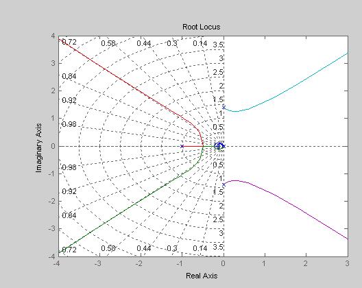
8 Uncompensated (P) >> s=tf('s'); >> Gp=15*(25/(s+5)^2)*((s+0.5)/(s+0.1))*((s+0.25)/(s+4))*((s^2+2*.05*12*s+144)/(s^2+2*.25*8*s+64)); >> rlocus(gp) >> sgrid >> [K,Poles]=rlocfind(G) Select a point in the graphics window sgrid selected_point = i K = Poles = i i i i >> Gce=1/(1+K*Gp)
9 Uncompensated (P) 1 lim sge ( s) = s 0 s
10 Uncompensated (P), error response to step
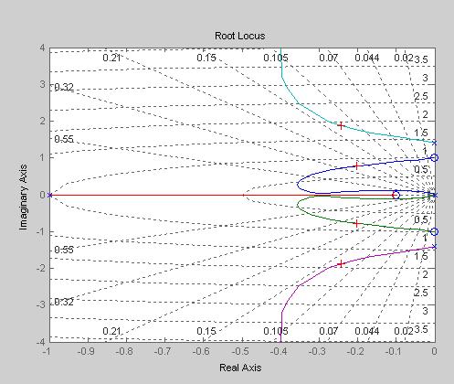
11 PI Stability limit >> [K,Poles]=rlocfind(G) Select a point in the graphics window selected_point = i K = Poles = i i i i i i
12 PI >> [K,Poles]=rlocfind(G) Select a point in the graphics window selected_point = i K = Poles = i i i i i i
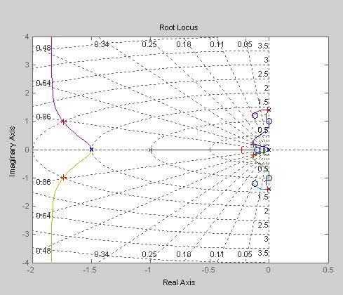
13 PI + Notch >> [K,Poles]=rlocfind(G) Select a point in the graphics window selected_point = i K = Poles = i i i i i i i i
14 PI + Notch
![PI + Notch Gain backed off a bit to achieve ~0.7 damping ratio >> [K,Poles]=rlocfind(G) Select a point in the graphics window selected_point = -3.3104 + 3.](/docs-images/88/116937023/images/15-0.jpg "3540i K = 0.0083 Poles = -10.3532 + 4.0115i -10.3532-4.0115i -2.0187 + 7.7728i -2.0187-7.7728i -3.2814 + 3.3222i -3.2814-3.3222i -2.6142-0.0896 + 0.0880i -0.")
15 PI + Notch Gain backed off a bit to achieve ~0.7 damping ratio >> [K,Poles]=rlocfind(G) Select a point in the graphics window selected_point = i K = Poles = i i i i i i i i

16 Hard Control Problems Control design problems can be difficult for many reasons: Demanding specifications Nonlinearity Actuator/sensor constraints Coupling Implementation constraints to name a few. But here are some deceptively simple issues involving linear SISO systems that can give a designer headaches. Non-collocated Nuclear plant pressure control Large spacecraft attitude Flexible rocket attitude Right half plane zero Most tail lift aircraft (space shuttle) Steam plant level control Bicycle with front wheel steering Right half plane pole Rotorcraft High performance aircraft (F-16) Some high performance ground vehicles Most missiles Both RHF pole and zero Some aircraft (X-29) Bicycle with rear wheel steering Inverted pendulum
17 Example: Collocated vs Non-collocated The goal is to position the load. A position sensor can be placed on motor or load. 2 s + k 1 J2 Θ 1 = T J1 2 2 ( J1+ J2) k s s + JJ 1 2 k 1 Θ 2 = T JJ ( J1+ J2) k s s + JJ 1 2 J = J = 1, k = T θ1 θ2 motor load flexible shaft
18 Example Cont d G θ 1 = s s 2 ( s + 2) Im Im G 1 θ = s ( s + 2) Re Re Collocated Noncollocated
19 Lead Compensation Collocated Non-collocated
 θ2")
20 Lead Response (collocated case) θ2 e = θ θ 1

21 Lead + Notch Collocated Non-collocated
22 Right Half Plane Zero First, let s look at the effect of a zero on the step response: ( ) = G( s) = G( s) = G s s y 1 1 s + 1 s 1 + 2s+ 1 s + 2s+ 1 s + 2s The RHP zero causes the output to initially move in the opposite direction t
 10s + 1 s s ( + 1) Try a PD compensator c = ( ) = ( + 1.")
23 Example: Simple Nonminimum Phase System Uncompensated Consider the process G p ( s) 10s + 1 s s ( + 1) Try a PD compensator c = ( ) = ( + 1.1) G s K s


24 Example with PD Poles look decent, but look at the initial error.
25 Example: Check Initial Error G G e e K = 1 1 = 1+ G 1+ K s+ 1.1 ( ) ( ) ( + 1) 2 ( s + s) + K( s+ 1.1)( 10s+ 1) ( + 1) 10s + 1 s s s( s ) 2 ( ) ( ) s s = = 1 10K s K s+ 1.1K (from MATLAB) s s Ge = s s e( 0 ) = lim sge ( s) = s s Initial Value Theorem
26 Comments on Positive Feedback Root Locus Interpreting the root locus presents a problem because the system involves positive feedback (equivalently, negative K when using a negative feedback loop). This is because of the negative sign in the transfer function. Note that computing the root locus with MATLAB does not present a problem. Positive feedback (or K<0) root locus rules are slightly different from the negative feedback rules. Here are the two changes. 4. Real-axis segments: For K < 0, real axis segments to the left of an even number of finite real axis poles and/or zeros are part of the root locus.
27 Positive Feedback Root Locus, Cont d 5. Behavior at infinity: The root locus approaches infinity along asymptotes with angles: 2kπ θ =, k = 0, ± 1, ± 2, ± 3, # finite poles # finite zeros Furthermore, these asymptotes intersect the real axis at a common point given by σ = finite poles finite zeros # finite poles # finite zeros
 s s ( s 0.730937)( s+ 1.7036)( s 2 + 0.")
 Unstable Pole p ( ) = ( ) G s G s s 26 s")
28 F-16, X-29 G p ( s) = ( )( s ) s s ( s )( s )( s s ) Unstable Pole p ( ) = ( ) G s G s s 26 s 6 RHP pole-zero pair Minimum phase part
Proportional plus Integral (PI) Controller
 Controller") Proportional plus Integral (PI) Controller 1. A pole is placed at the origin 2. This causes the system type to increase by 1 and as a result the error is reduced to zero. 3. Originally a point A is on
Proportional plus Integral (PI) Controller 1. A pole is placed at the origin 2. This causes the system type to increase by 1 and as a result the error is reduced to zero. 3. Originally a point A is on
Contents. PART I METHODS AND CONCEPTS 2. Transfer Function Approach Frequency Domain Representations... 42
 Contents Preface.............................................. xiii 1. Introduction......................................... 1 1.1 Continuous and Discrete Control Systems................. 4 1.2 Open-Loop
1 Chapter 9: Design via Root Locus
 1 Figure 9.1 a. Sample root locus, showing possible design point via gain adjustment (A) and desired design point that cannot be met via simple gain adjustment (B); b. responses from poles at A and B 2
The Root Locus Method
 The Root Locu Method MEM 355 Performance Enhancement of Dynamical Sytem Harry G. Kwatny Department of Mechanical Engineering & Mechanic Drexel Univerity Outline The root locu method wa introduced by Evan
Intro to Frequency Domain Design
 Intro to Frequency Domain Design MEM 355 Performance Enhancement of Dynamical Systems Harry G. Kwatny Department of Mechanical Engineering & Mechanics Drexel University Outline Closed Loop Transfer Functions
MEM 355 Performance Enhancement of Dynamical Systems
 MEM 355 Performance Enhancement of Dynamical Systems Frequency Domain Design Intro Harry G. Kwatny Department of Mechanical Engineering & Mechanics Drexel University /5/27 Outline Closed Loop Transfer
Root Locus Techniques
 4th Edition E I G H T Root Locus Techniques SOLUTIONS TO CASE STUDIES CHALLENGES Antenna Control: Transient Design via Gain a. From the Chapter 5 Case Study Challenge: 76.39K G(s) = s(s+50)(s+.32) Since
The loop shaping paradigm. Lecture 7. Loop analysis of feedback systems (2) Essential specifications (2)
 Essential specifications (2)") Lecture 7. Loop analysis of feedback systems (2). Loop shaping 2. Performance limitations The loop shaping paradigm. Estimate performance and robustness of the feedback system from the loop transfer L(jω)
Lecture 7. Loop analysis of feedback systems (2). Loop shaping 2. Performance limitations The loop shaping paradigm. Estimate performance and robustness of the feedback system from the loop transfer L(jω)
MEM 355 Performance Enhancement of Dynamical Systems
 MEM 355 Performance Enhancement of Dynamical Systems Frequency Domain Design Harry G. Kwatny Department of Mechanical Engineering & Mechanics Drexel University 5/8/25 Outline Closed Loop Transfer Functions
School of Mechanical Engineering Purdue University. DC Motor Position Control The block diagram for position control of the servo table is given by:
 Root Locus Motivation Sketching Root Locus Examples ME375 Root Locus - 1 Servo Table Example DC Motor Position Control The block diagram for position control of the servo table is given by: θ D 0.09 See
Systems Analysis and Control
 Systems Analysis and Control Matthew M. Peet Arizona State University Lecture 6: Generalized and Controller Design Overview In this Lecture, you will learn: Generalized? What about changing OTHER parameters
Outline. Classical Control. Lecture 5
 Outline Outline Outline 1 What is 2 Outline What is Why use? Sketching a 1 What is Why use? Sketching a 2 Gain Controller Lead Compensation Lag Compensation What is Properties of a General System Why use?
EE C128 / ME C134 Fall 2014 HW 6.2 Solutions. HW 6.2 Solutions
 EE C28 / ME C34 Fall 24 HW 6.2 Solutions. PI Controller For the system G = K (s+)(s+3)(s+8) HW 6.2 Solutions in negative feedback operating at a damping ratio of., we are going to design a PI controller
MEM 355 Performance Enhancement of Dynamical Systems Root Locus Analysis
 MEM 355 Performance Enhancement of Dynamical Sytem Root Locu Analyi Harry G. Kwatny Department of Mechanical Engineering & Mechanic Drexel Univerity Outline The root locu method wa introduced by Evan in
PD, PI, PID Compensation. M. Sami Fadali Professor of Electrical Engineering University of Nevada
 PD, PI, PID Compensation M. Sami Fadali Professor of Electrical Engineering University of Nevada 1 Outline PD compensation. PI compensation. PID compensation. 2 PD Control L= loop gain s cl = desired closed-loop
MEM 355 Performance Enhancement of Dynamical Systems
 MEM 355 Performance Enhancement of Dynamical Systems State Space Design Harry G. Kwatny Department of Mechanical Engineering & Mechanics Drexel University 11/8/2016 Outline State space techniques emerged
Course Summary. The course cannot be summarized in one lecture.
 Course Summary Unit 1: Introduction Unit 2: Modeling in the Frequency Domain Unit 3: Time Response Unit 4: Block Diagram Reduction Unit 5: Stability Unit 6: Steady-State Error Unit 7: Root Locus Techniques
Methods for analysis and control of. Lecture 4: The root locus design method
 Methods for analysis and control of Lecture 4: The root locus design method O. Sename 1 1 Gipsa-lab, CNRS-INPG, FRANCE Olivier.Sename@gipsa-lab.inpg.fr www.lag.ensieg.inpg.fr/sename Lead Lag 17th March
1 An Overview and Brief History of Feedback Control 1. 2 Dynamic Models 23. Contents. Preface. xiii
 Contents 1 An Overview and Brief History of Feedback Control 1 A Perspective on Feedback Control 1 Chapter Overview 2 1.1 A Simple Feedback System 3 1.2 A First Analysis of Feedback 6 1.3 Feedback System
State Space Design. MEM 355 Performance Enhancement of Dynamical Systems
 State Space Design MEM 355 Performance Enhancement of Dynamical Systems Harry G. Kwatny Department of Mechanical Engineering & Mechanics Drexel University Outline State space techniques emerged around
Root Locus. Motivation Sketching Root Locus Examples. School of Mechanical Engineering Purdue University. ME375 Root Locus - 1
 Root Locus Motivation Sketching Root Locus Examples ME375 Root Locus - 1 Servo Table Example DC Motor Position Control The block diagram for position control of the servo table is given by: D 0.09 Position
Homework 7 - Solutions
 Homework 7 - Solutions Note: This homework is worth a total of 48 points. 1. Compensators (9 points) For a unity feedback system given below, with G(s) = K s(s + 5)(s + 11) do the following: (c) Find the
Ultimate State. MEM 355 Performance Enhancement of Dynamical Systems
 Ultimate State MEM 355 Performance Enhancement of Dnamical Sstems Harr G. Kwatn Department of Mechanical Engineering & Mechanics Drexel Universit Outline Design Criteria two step process Ultimate state
Feedback Control of Linear SISO systems. Process Dynamics and Control
 Feedback Control of Linear SISO systems Process Dynamics and Control 1 Open-Loop Process The study of dynamics was limited to open-loop systems Observe process behavior as a result of specific input signals
7.4 STEP BY STEP PROCEDURE TO DRAW THE ROOT LOCUS DIAGRAM
 ROOT LOCUS TECHNIQUE. Values of on the root loci The value of at any point s on the root loci is determined from the following equation G( s) H( s) Product of lengths of vectors from poles of G( s)h( s)
Systems Analysis and Control
 Systems Analysis and Control Matthew M. Peet Illinois Institute of Technology Lecture 23: Drawing The Nyquist Plot Overview In this Lecture, you will learn: Review of Nyquist Drawing the Nyquist Plot Using
ME 375 Final Examination Thursday, May 7, 2015 SOLUTION
 ME 375 Final Examination Thursday, May 7, 2015 SOLUTION POBLEM 1 (25%) negligible mass wheels negligible mass wheels v motor no slip ω r r F D O no slip e in Motor% Cart%with%motor%a,ached% The coupled
Video 5.1 Vijay Kumar and Ani Hsieh
 Video 5.1 Vijay Kumar and Ani Hsieh Robo3x-1.1 1 The Purpose of Control Input/Stimulus/ Disturbance System or Plant Output/ Response Understand the Black Box Evaluate the Performance Change the Behavior
Robust Control 9 Design Summary & Examples
 Robust Control 9 Design Summary & Examples Harry G. Kwatny Department of Mechanical Engineering & Mechanics Drexel University 5/6/003 Outline he H Problem Solution via γ-iteration Robust stability via
Methods for analysis and control of dynamical systems Lecture 4: The root locus design method
 Methods for analysis and control of Lecture 4: The root locus design method O. Sename 1 1 Gipsa-lab, CNRS-INPG, FRANCE Olivier.Sename@gipsa-lab.inpg.fr www.gipsa-lab.fr/ o.sename 5th February 2015 Outline
Bangladesh University of Engineering and Technology. EEE 402: Control System I Laboratory
 Bangladesh University of Engineering and Technology Electrical and Electronic Engineering Department EEE 402: Control System I Laboratory Experiment No. 4 a) Effect of input waveform, loop gain, and system
ELECTRONICS & COMMUNICATIONS DEP. 3rd YEAR, 2010/2011 CONTROL ENGINEERING SHEET 5 Lead-Lag Compensation Techniques
 CAIRO UNIVERSITY FACULTY OF ENGINEERING ELECTRONICS & COMMUNICATIONS DEP. 3rd YEAR, 00/0 CONTROL ENGINEERING SHEET 5 Lead-Lag Compensation Techniques [] For the following system, Design a compensator such
MAS107 Control Theory Exam Solutions 2008
 MAS07 CONTROL THEORY. HOVLAND: EXAM SOLUTION 2008 MAS07 Control Theory Exam Solutions 2008 Geir Hovland, Mechatronics Group, Grimstad, Norway June 30, 2008 C. Repeat question B, but plot the phase curve
100 (s + 10) (s + 100) e 0.5s. s 100 (s + 10) (s + 100). G(s) =
 (s + 100) e 0.5s. s 100 (s + 10) (s + 100). G(s) =") 1 AME 3315; Spring 215; Midterm 2 Review (not graded) Problems: 9.3 9.8 9.9 9.12 except parts 5 and 6. 9.13 except parts 4 and 5 9.28 9.34 You are given the transfer function: G(s) = 1) Plot the bode plot
1 AME 3315; Spring 215; Midterm 2 Review (not graded) Problems: 9.3 9.8 9.9 9.12 except parts 5 and 6. 9.13 except parts 4 and 5 9.28 9.34 You are given the transfer function: G(s) = 1) Plot the bode plot
Exercises for lectures 13 Design using frequency methods
 Exercises for lectures 13 Design using frequency methods Michael Šebek Automatic control 2016 31-3-17 Setting of the closed loop bandwidth At the transition frequency in the open loop is (from definition)
Essence of the Root Locus Technique
 Essence of the Root Locus Technique In this chapter we study a method for finding locations of system poles. The method is presented for a very general set-up, namely for the case when the closed-loop
EE3CL4: Introduction to Linear Control Systems
 1 / 17 EE3CL4: Introduction to Linear Control Systems Section 7: McMaster University Winter 2018 2 / 17 Outline 1 4 / 17 Cascade compensation Throughout this lecture we consider the case of H(s) = 1. We
Pitch Rate CAS Design Project
 Pitch Rate CAS Design Project Washington University in St. Louis MAE 433 Control Systems Bob Rowe 4.4.7 Design Project Part 2 This is the second part of an ongoing project to design a control and stability
AMME3500: System Dynamics & Control
 Stefan B. Williams May, 211 AMME35: System Dynamics & Control Assignment 4 Note: This assignment contributes 15% towards your final mark. This assignment is due at 4pm on Monday, May 3 th during Week 13
Variable Structure Control ~ Disturbance Rejection. Harry G. Kwatny Department of Mechanical Engineering & Mechanics Drexel University
 Variable Structure Control ~ Disturbance Rejection Harry G. Kwatny Department of Mechanical Engineering & Mechanics Drexel University Outline Linear Tracking & Disturbance Rejection Variable Structure
6.1 Sketch the z-domain root locus and find the critical gain for the following systems K., the closed-loop characteristic equation is K + z 0.
 6. Sketch the z-domain root locus and find the critical gain for the following systems K (i) Gz () z 4. (ii) Gz K () ( z+ 9. )( z 9. ) (iii) Gz () Kz ( z. )( z ) (iv) Gz () Kz ( + 9. ) ( z. )( z 8. ) (i)
Robust Control 3 The Closed Loop
 Robust Control 3 The Closed Loop Harry G. Kwatny Department of Mechanical Engineering & Mechanics Drexel University /2/2002 Outline Closed Loop Transfer Functions Traditional Performance Measures Time
Unit 8: Part 2: PD, PID, and Feedback Compensation
 Ideal Derivative Compensation (PD) Lead Compensation PID Controller Design Feedback Compensation Physical Realization of Compensation Unit 8: Part 2: PD, PID, and Feedback Compensation Engineering 5821:
Input-output Controllability Analysis
 Input-output Controllability Analysis Idea: Find out how well the process can be controlled - without having to design a specific controller Note: Some processes are impossible to control Reference: S.
Linear System Theory. Wonhee Kim Lecture 1. March 7, 2018
 Linear System Theory Wonhee Kim Lecture 1 March 7, 2018 1 / 22 Overview Course Information Prerequisites Course Outline What is Control Engineering? Examples of Control Systems Structure of Control Systems
ECE 345 / ME 380 Introduction to Control Systems Lecture Notes 8
 Learning Objectives ECE 345 / ME 380 Introduction to Control Systems Lecture Notes 8 Dr. Oishi oishi@unm.edu November 2, 203 State the phase and gain properties of a root locus Sketch a root locus, by
Lecture 14 - Using the MATLAB Control System Toolbox and Simulink Friday, February 8, 2013
 Today s Objectives ENGR 105: Feedback Control Design Winter 2013 Lecture 14 - Using the MATLAB Control System Toolbox and Simulink Friday, February 8, 2013 1. introduce the MATLAB Control System Toolbox
Compensator Design to Improve Transient Performance Using Root Locus
 1 Compensator Design to Improve Transient Performance Using Root Locus Prof. Guy Beale Electrical and Computer Engineering Department George Mason University Fairfax, Virginia Correspondence concerning
Chapter Eleven. Frequency Domain Design Sensitivity Functions
 Feedback Systems by Astrom and Murray, v2.11b http://www.cds.caltech.edu/~murray/fbswiki Chapter Eleven Frequency Domain Design Sensitivity improvements in one frequency range must be paid for with sensitivity
Dynamic Compensation using root locus method
 CAIRO UNIVERSITY FACULTY OF ENGINEERING ELECTRONICS & COMMUNICATIONS DEP. 3rd YEAR, 00/0 CONTROL ENGINEERING SHEET 9 Dynamic Compensation using root locus method [] (Final00)For the system shown in the
Lecture 6 Classical Control Overview IV. Dr. Radhakant Padhi Asst. Professor Dept. of Aerospace Engineering Indian Institute of Science - Bangalore
 Lecture 6 Classical Control Overview IV Dr. Radhakant Padhi Asst. Professor Dept. of Aerospace Engineering Indian Institute of Science - Bangalore Lead Lag Compensator Design Dr. Radhakant Padhi Asst.
Due Wednesday, February 6th EE/MFS 599 HW #5
 Due Wednesday, February 6th EE/MFS 599 HW #5 You may use Matlab/Simulink wherever applicable. Consider the standard, unity-feedback closed loop control system shown below where G(s) = /[s q (s+)(s+9)]
Root Locus Methods. The root locus procedure
 Root Locus Methods Design of a position control system using the root locus method Design of a phase lag compensator using the root locus method The root locus procedure To determine the value of the gain
9/9/2011 Classical Control 1
 MM11 Root Locus Design Method Reading material: FC pp.270-328 9/9/2011 Classical Control 1 What have we talked in lecture (MM10)? Lead and lag compensators D(s)=(s+z)/(s+p) with z < p or z > p D(s)=K(Ts+1)/(Ts+1),
ECEn 483 / ME 431 Case Studies. Randal W. Beard Brigham Young University
 ECEn 483 / ME 431 Case Studies Randal W. Beard Brigham Young University Updated: December 2, 2014 ii Contents 1 Single Link Robot Arm 1 2 Pendulum on a Cart 9 3 Satellite Attitude Control 17 4 UUV Roll
Topic # Feedback Control Systems
 Topic #1 16.31 Feedback Control Systems Motivation Basic Linear System Response Fall 2007 16.31 1 1 16.31: Introduction r(t) e(t) d(t) y(t) G c (s) G(s) u(t) Goal: Design a controller G c (s) so that the
Dr Ian R. Manchester Dr Ian R. Manchester AMME 3500 : Review
 Week Date Content Notes 1 6 Mar Introduction 2 13 Mar Frequency Domain Modelling 3 20 Mar Transient Performance and the s-plane 4 27 Mar Block Diagrams Assign 1 Due 5 3 Apr Feedback System Characteristics
Plan of the Lecture. Goal: wrap up lead and lag control; start looking at frequency response as an alternative methodology for control systems design.
 Plan of the Lecture Review: design using Root Locus; dynamic compensation; PD and lead control Today s topic: PI and lag control; introduction to frequency-response design method Goal: wrap up lead and
Chapter 9: Controller design
 Chapter 9. Controller Design 9.1. Introduction 9.2. Effect of negative feedback on the network transfer functions 9.2.1. Feedback reduces the transfer function from disturbances to the output 9.2.2. Feedback
MASSACHUSETTS INSTITUTE OF TECHNOLOGY Department of Mechanical Engineering 2.04A Systems and Controls Spring 2013
 MASSACHUSETTS INSTITUTE OF TECHNOLOGY Department of Mechanical Engineering 2.04A Systems and Controls Spring 2013 Problem Set #4 Posted: Thursday, Mar. 7, 13 Due: Thursday, Mar. 14, 13 1. Sketch the Root
Course roadmap. ME451: Control Systems. What is Root Locus? (Review) Characteristic equation & root locus. Lecture 18 Root locus: Sketch of proofs
 Characteristic equation & root locus. Lecture 18 Root locus: Sketch of proofs") ME451: Control Systems Modeling Course roadmap Analysis Design Lecture 18 Root locus: Sketch of proofs Dr. Jongeun Choi Department of Mechanical Engineering Michigan State University Laplace transform
ME451: Control Systems Modeling Course roadmap Analysis Design Lecture 18 Root locus: Sketch of proofs Dr. Jongeun Choi Department of Mechanical Engineering Michigan State University Laplace transform
Root Locus Design Example #4
 Root Locus Design Example #4 A. Introduction The plant model represents a linearization of the heading dynamics of a 25, ton tanker ship under empty load conditions. The reference input signal R(s) is
Control Systems I. Lecture 6: Poles and Zeros. Readings: Emilio Frazzoli. Institute for Dynamic Systems and Control D-MAVT ETH Zürich
 Control Systems I Lecture 6: Poles and Zeros Readings: Emilio Frazzoli Institute for Dynamic Systems and Control D-MAVT ETH Zürich October 27, 2017 E. Frazzoli (ETH) Lecture 6: Control Systems I 27/10/2017
Dr Ian R. Manchester Dr Ian R. Manchester AMME 3500 : Root Locus
 Week Content Notes 1 Introduction 2 Frequency Domain Modelling 3 Transient Performance and the s-plane 4 Block Diagrams 5 Feedback System Characteristics Assign 1 Due 6 Root Locus 7 Root Locus 2 Assign
Chemical Process Dynamics and Control. Aisha Osman Mohamed Ahmed Department of Chemical Engineering Faculty of Engineering, Red Sea University
 Chemical Process Dynamics and Control Aisha Osman Mohamed Ahmed Department of Chemical Engineering Faculty of Engineering, Red Sea University 1 Chapter 4 System Stability 2 Chapter Objectives End of this
Lecture 25: Tue Nov 27, 2018
 Lecture 25: Tue Nov 27, 2018 Reminder: Lab 3 moved to Tuesday Dec 4 Lecture: review time-domain characteristics of 2nd-order systems intro to control: feedback open-loop vs closed-loop control intro to
Systems Analysis and Control
 Systems Analysis and Control Matthew M. Peet Arizona State University Lecture 23: Drawing The Nyquist Plot Overview In this Lecture, you will learn: Review of Nyquist Drawing the Nyquist Plot Using the
MAE143a: Signals & Systems (& Control) Final Exam (2011) solutions
 Final Exam (2011) solutions") MAE143a: Signals & Systems (& Control) Final Exam (2011) solutions Question 1. SIGNALS: Design of a noise-cancelling headphone system. 1a. Based on the low-pass filter given, design a high-pass filter,
MAE143a: Signals & Systems (& Control) Final Exam (2011) solutions Question 1. SIGNALS: Design of a noise-cancelling headphone system. 1a. Based on the low-pass filter given, design a high-pass filter,
Controller Design using Root Locus
 Chapter 4 Controller Design using Root Locus 4. PD Control Root locus is a useful tool to design different types of controllers. Below, we will illustrate the design of proportional derivative controllers
Laboratory 11 Control Systems Laboratory ECE3557. State Feedback Controller for Position Control of a Flexible Joint
 Laboratory 11 State Feedback Controller for Position Control of a Flexible Joint 11.1 Objective The objective of this laboratory is to design a full state feedback controller for endpoint position control
Systems Analysis and Control
 Systems Analysis and Control Matthew M. Peet Illinois Institute of Technology Lecture 22: The Nyquist Criterion Overview In this Lecture, you will learn: Complex Analysis The Argument Principle The Contour
Single-Input-Single-Output Systems
 TF 502 Single-Input-Single-Output Systems SIST, ShanghaiTech Introduction Open-Loop Control-Response Proportional Control General PID Control Boris Houska 1-1 Contents Introduction Open-Loop Control-Response
Analysis and Synthesis of Single-Input Single-Output Control Systems
 Lino Guzzella Analysis and Synthesis of Single-Input Single-Output Control Systems l+kja» \Uja>)W2(ja»\ um Contents 1 Definitions and Problem Formulations 1 1.1 Introduction 1 1.2 Definitions 1 1.2.1 Systems
(b) A unity feedback system is characterized by the transfer function. Design a suitable compensator to meet the following specifications:
 A unity feedback system is characterized by the transfer function. Design a suitable compensator to meet the following specifications:") 1. (a) The open loop transfer function of a unity feedback control system is given by G(S) = K/S(1+0.1S)(1+S) (i) Determine the value of K so that the resonance peak M r of the system is equal to 1.4.
1. (a) The open loop transfer function of a unity feedback control system is given by G(S) = K/S(1+0.1S)(1+S) (i) Determine the value of K so that the resonance peak M r of the system is equal to 1.4.
Vehicle longitudinal speed control
 Vehicle longitudinal speed control Prof. R.G. Longoria Department of Mechanical Engineering The University of Texas at Austin February 10, 2015 1 Introduction 2 Control concepts Open vs. Closed Loop Control
Chapter 2 SDOF Vibration Control 2.1 Transfer Function
 Chapter SDOF Vibration Control.1 Transfer Function mx ɺɺ( t) + cxɺ ( t) + kx( t) = F( t) Defines the transfer function as output over input X ( s) 1 = G( s) = (1.39) F( s) ms + cs + k s is a complex number:
Introduction to Feedback Control
 Introduction to Feedback Control Control System Design Why Control? Open-Loop vs Closed-Loop (Feedback) Why Use Feedback Control? Closed-Loop Control System Structure Elements of a Feedback Control System
Collocated versus non-collocated control [H04Q7]
![Collocated versus non-collocated control [H04Q7]](/thumbs/86/93671615.jpg "Collocated versus non-collocated control [H04Q7]") Collocated versus non-collocated control [H04Q7] Jan Swevers September 2008 0-0 Contents Some concepts of structural dynamics Collocated versus non-collocated control Summary This lecture is based on parts
Collocated versus non-collocated control [H04Q7] Jan Swevers September 2008 0-0 Contents Some concepts of structural dynamics Collocated versus non-collocated control Summary This lecture is based on parts
D(s) G(s) A control system design definition
 G(s) A control system design definition") R E Compensation D(s) U Plant G(s) Y Figure 7. A control system design definition x x x 2 x 2 U 2 s s 7 2 Y Figure 7.2 A block diagram representing Eq. (7.) in control form z U 2 s z Y 4 z 2 s z 2 3 Figure
R E Compensation D(s) U Plant G(s) Y Figure 7. A control system design definition x x x 2 x 2 U 2 s s 7 2 Y Figure 7.2 A block diagram representing Eq. (7.) in control form z U 2 s z Y 4 z 2 s z 2 3 Figure
EECS C128/ ME C134 Final Wed. Dec. 15, am. Closed book. Two pages of formula sheets. No calculators.
 Name: SID: EECS C28/ ME C34 Final Wed. Dec. 5, 2 8- am Closed book. Two pages of formula sheets. No calculators. There are 8 problems worth points total. Problem Points Score 2 2 6 3 4 4 5 6 6 7 8 2 Total
PM diagram of the Transfer Function and its use in the Design of Controllers
 PM diagram of the Transfer Function and its use in the Design of Controllers Santiago Garrido, Luis Moreno Abstract This paper presents the graphical chromatic representation of the phase and the magnitude
Design of a Lead Compensator
 Design of a Lead Compensator Dr. Bishakh Bhattacharya Professor, Department of Mechanical Engineering IIT Kanpur Joint Initiative of IITs and IISc - Funded by MHRD The Lecture Contains Standard Forms of
Systems Engineering/Process Control L1
 Systems Engineering/Process Control L1 What is Systems Engineering/Process Control? Graphical system representations Fundamental control principles Reading: Systems Engineering and Process Control: 1.1
Lecture 5 Classical Control Overview III. Dr. Radhakant Padhi Asst. Professor Dept. of Aerospace Engineering Indian Institute of Science - Bangalore
 Lecture 5 Classical Control Overview III Dr. Radhakant Padhi Asst. Professor Dept. of Aerospace Engineering Indian Institute of Science - Bangalore A Fundamental Problem in Control Systems Poles of open
FREQUENCY-RESPONSE DESIGN
 ECE45/55: Feedback Control Systems. 9 FREQUENCY-RESPONSE DESIGN 9.: PD and lead compensation networks The frequency-response methods we have seen so far largely tell us about stability and stability margins
Tradeoffs and Limits of Performance
 Chapter 9 Tradeoffs and Limits of Performance 9. Introduction Fundamental limits of feedback systems will be investigated in this chapter. We begin in Section 9.2 by discussing the basic feedback loop
Solutions for Tutorial 10 Stability Analysis
 Solutions for Tutorial 1 Stability Analysis 1.1 In this question, you will analyze the series of three isothermal CSTR s show in Figure 1.1. The model for each reactor is the same at presented in Textbook
CYBER EXPLORATION LABORATORY EXPERIMENTS
 CYBER EXPLORATION LABORATORY EXPERIMENTS 1 2 Cyber Exploration oratory Experiments Chapter 2 Experiment 1 Objectives To learn to use MATLAB to: (1) generate polynomial, (2) manipulate polynomials, (3)
Root Locus Design Example #3
 Root Locus Design Example #3 A. Introduction The system represents a linear model for vertical motion of an underwater vehicle at zero forward speed. The vehicle is assumed to have zero pitch and roll
State Feedback Controller for Position Control of a Flexible Link
 Laboratory 12 Control Systems Laboratory ECE3557 Laboratory 12 State Feedback Controller for Position Control of a Flexible Link 12.1 Objective The objective of this laboratory is to design a full state
Module 3F2: Systems and Control EXAMPLES PAPER 2 ROOT-LOCUS. Solutions
 Cambridge University Engineering Dept. Third Year Module 3F: Systems and Control EXAMPLES PAPER ROOT-LOCUS Solutions. (a) For the system L(s) = (s + a)(s + b) (a, b both real) show that the root-locus
Systems Analysis and Control
 Systems Analysis and Control Matthew M. Peet Arizona State University Lecture 21: Stability Margins and Closing the Loop Overview In this Lecture, you will learn: Closing the Loop Effect on Bode Plot Effect
EE C128 / ME C134 Fall 2014 HW 8 - Solutions. HW 8 - Solutions
 EE C28 / ME C34 Fall 24 HW 8 - Solutions HW 8 - Solutions. Transient Response Design via Gain Adjustment For a transfer function G(s) = in negative feedback, find the gain to yield a 5% s(s+2)(s+85) overshoot
1 x(k +1)=(Φ LH) x(k) = T 1 x 2 (k) x1 (0) 1 T x 2(0) T x 1 (0) x 2 (0) x(1) = x(2) = x(3) =
=(Φ LH) x(k) = T 1 x 2 (k) x1 (0) 1 T x 2(0) T x 1 (0) x 2 (0) x(1) = x(2) = x(3) =") 567 This is often referred to as Þnite settling time or deadbeat design because the dynamics will settle in a Þnite number of sample periods. This estimator always drives the error to zero in time 2T or
567 This is often referred to as Þnite settling time or deadbeat design because the dynamics will settle in a Þnite number of sample periods. This estimator always drives the error to zero in time 2T or
ECSE 4962 Control Systems Design. A Brief Tutorial on Control Design
 ECSE 4962 Control Systems Design A Brief Tutorial on Control Design Instructor: Professor John T. Wen TA: Ben Potsaid http://www.cat.rpi.edu/~wen/ecse4962s04/ Don t Wait Until The Last Minute! You got
ECE 486 Control Systems
 ECE 486 Control Systems Spring 208 Midterm #2 Information Issued: April 5, 208 Updated: April 8, 208 ˆ This document is an info sheet about the second exam of ECE 486, Spring 208. ˆ Please read the following
University of Utah Electrical & Computer Engineering Department ECE 3510 Lab 9 Inverted Pendulum
 University of Utah Electrical & Computer Engineering Department ECE 3510 Lab 9 Inverted Pendulum p1 ECE 3510 Lab 9, Inverted Pendulum M. Bodson, A. Stolp, 4/2/13 rev, 4/9/13 Objectives The objective of
Inverted Pendulum. Objectives
 Inverted Pendulum Objectives The objective of this lab is to experiment with the stabilization of an unstable system. The inverted pendulum problem is taken as an example and the animation program gives
Automatic Control II Computer exercise 3. LQG Design
 Uppsala University Information Technology Systems and Control HN,FS,KN 2000-10 Last revised by HR August 16, 2017 Automatic Control II Computer exercise 3 LQG Design Preparations: Read Chapters 5 and 9
INTRODUCTION TO DIGITAL CONTROL
 ECE4540/5540: Digital Control Systems INTRODUCTION TO DIGITAL CONTROL.: Introduction In ECE450/ECE550 Feedback Control Systems, welearnedhow to make an analog controller D(s) to control a linear-time-invariant