Systems Engineering and Control
|
|
|
- Pierce Maxwell
- 5 years ago
- Views:
Transcription
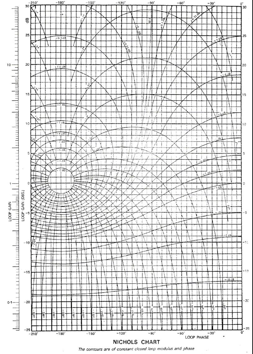
1 Cork Institute of Technology Bachelor of Engineering (Honours) in Mechanical Engineering - Award (NFQ Level 8) Autumn 2007 Systems Engineering and Control (Time: 3 Hours) Answer any FIVE Questions Examiners: Prof. M. Gilchrist ALL questions carry equal marks. Mr. P. Clarke Dr. M. J. O Mahony 1. Fig Q.1 shows a block diagram of chemical reactor system. (a) (b) Construct the Bode plot for the system as ω varies from 0.01 to 100 rad/s and hence obtain the gain margin and phase margin. (8 marks) Represent the system response on the Nichols chart and hence determine the following system parameters: (i) Gain and Phase Margins (ii) Resonant Peak M r (iii) Resonant Frequency ω r (iv) Bandwidth ω b. (8 marks) (c) Comment on the results obtained and sketch the system response to a unitstep input in the time domain. (4 marks) 2. (a) State the Nyquist Stability Criterion. (4 marks) (b) Plot the Nyquist Contour for the system with the following open loop transfer function; K GsHs () () = ()( s Ts 1 + 1)( T2s+ 1) Comment on the stability of the system. (8 marks) (c) If T 1 = 0.05, T 2 = 0.2 and K =1 i. Find the GM for the system. ii. Determine the value of K that will give a phase margin of 40 o. (8 marks)
2 3. An automatic temperature control loop for heating methanol using low pressure steam plant is shown in Fig. Q3. The following parameters relate to the system block diagram: K d = K h = Input/Feedback gain factors = 0.16 ma/ o C K v = Control valve coefficient = 0.1 Kg/s per ma K e = Heat Exchange gain = 100 o C per Kg/s (of steam) K T = Sensitivity of T PO to T Pi = 1 o C/ o C τ v = Control valve time constant = 5 s τ e = Heat Exchanger time constant= 20 s G c (s) is initially set as a proportional controller. (a) (i) Determine the closed loop gain ( T PO (s)/ T P(set) (s)) (ii) Determine the response of the system output to process inlet temperature disturbance ( T PO (s)/ T Pi (s)), in the static case only. (iii) Analyse the effect of varying the proportional gain on the methanol outlet temperature. Assume that T P(set) = 100 o C (iv) Analyse the effect of varying the proportional gain on the methanol outlet temperature due to a disturbance input due to variations in the input temperature of the methanol ( T Pi (s)). Assume that T Pi = 10 o C (10 marks) (b) A disturbance due to variations in the input temperature of the methanol ( T Pi (s)) will on occasion enter the system. Suggest a suitable control strategy that will minimise the effect of the disturbance on the process output temperature (T PO (s)). The temperature disturbance cannot be controlled but it can be measured. Show the implementation of your proposed control strategy on a modified block diagram of the system. How would full dynamic compensation be achieved? (8 marks) Discuss the factors that would influence the choice of a particular controller configuration. (2 marks) 4. (a) Investigate the behaviour of the relay operated motor control system shown in Figure Q4. Is the system stable? (12 marks) (b) Assuming r(t)=0 sketch the waveforms corresponding to n(t) and c(t). Comment on the frequency spectrum of these signals. (8 marks)
3 5. (a) Consider the temperature control system for the large test chamber shown in Figure Q5. Given that D(z)=6, transform this diagram into the Z-domain and hence obtain the open loop transfer function GH(z) and the closed loop transfer function Y(z)/R(z). (14 marks) (b) Plot the root locus for the system in the z-plane and describe the expected response to a unit step input. (6 marks) 6. (a) In the analysis of digital control systems discuss the relationships between the s-plane, the z-plane and the w-plane. (10 marks) (b) A microprocessor-based control system with a sampling time T of 0.01 sec. has the following open loop transfer function: 12. GzHz () () = z 08. Determine the gain and phase margins of the system and comment on its stability. (10 marks) 7. Write detailed technical accounts on any TWO of the following: (i) (ii) (iii) Cascade Control ISA (R1992) Symbols and Identification Smith predictor (dead time compensation) (10 marks x 2)
4 R(s) ( s+ 4)( s+ 10) 2 0.1s e s C(s) Sensor 1 Fig Q1: Chemical reactor system T Pi (s) Set Point Temperature Controller Control Valve Heat exchanger Dynamics K T T P(set) (s) K d Signal conversion + - G c (s) K v τ v s+1 K e τ e s +1 + T PO (s) Actual Temperature Temp Sensor/Transmitter K h Fig. Q3 Power Amplifier r(t) + - m(t) n(t) G p (s) Plant 100 ()( s s+ 1)( s+ 10) c(t) Fig Q4
5 Compensator ZOH Test chamber R(s) + - T=2s D(z) 1 e s Ts M () s s + 1 Y(s) o C 2 Fig. Q5
6
7
8
9
10
11
12
KINGS COLLEGE OF ENGINEERING DEPARTMENT OF ELECTRONICS AND COMMUNICATION ENGINEERING
 KINGS COLLEGE OF ENGINEERING DEPARTMENT OF ELECTRONICS AND COMMUNICATION ENGINEERING QUESTION BANK SUB.NAME : CONTROL SYSTEMS BRANCH : ECE YEAR : II SEMESTER: IV 1. What is control system? 2. Define open
VALLIAMMAI ENGINEERING COLLEGE SRM Nagar, Kattankulathur
 VALLIAMMAI ENGINEERING COLLEGE SRM Nagar, Kattankulathur 603 203. DEPARTMENT OF ELECTRONICS & COMMUNICATION ENGINEERING SUBJECT QUESTION BANK : EC6405 CONTROL SYSTEM ENGINEERING SEM / YEAR: IV / II year
ELECTRONICS & COMMUNICATIONS DEP. 3rd YEAR, 2010/2011 CONTROL ENGINEERING SHEET 5 Lead-Lag Compensation Techniques
 CAIRO UNIVERSITY FACULTY OF ENGINEERING ELECTRONICS & COMMUNICATIONS DEP. 3rd YEAR, 00/0 CONTROL ENGINEERING SHEET 5 Lead-Lag Compensation Techniques [] For the following system, Design a compensator such
R10 JNTUWORLD B 1 M 1 K 2 M 2. f(t) Figure 1
 Figure 1") Code No: R06 R0 SET - II B. Tech II Semester Regular Examinations April/May 03 CONTROL SYSTEMS (Com. to EEE, ECE, EIE, ECC, AE) Time: 3 hours Max. Marks: 75 Answer any FIVE Questions All Questions carry
Code No: R06 R0 SET - II B. Tech II Semester Regular Examinations April/May 03 CONTROL SYSTEMS (Com. to EEE, ECE, EIE, ECC, AE) Time: 3 hours Max. Marks: 75 Answer any FIVE Questions All Questions carry
DEPARTMENT OF ELECTRICAL AND ELECTRONICS ENGINEERING
 KINGS COLLEGE OF ENGINEERING DEPARTMENT OF ELECTRICAL AND ELECTRONICS ENGINEERING QUESTION BANK SUBJECT CODE & NAME: CONTROL SYSTEMS YEAR / SEM: II / IV UNIT I SYSTEMS AND THEIR REPRESENTATION PARTA [2
(b) A unity feedback system is characterized by the transfer function. Design a suitable compensator to meet the following specifications:
 A unity feedback system is characterized by the transfer function. Design a suitable compensator to meet the following specifications:") 1. (a) The open loop transfer function of a unity feedback control system is given by G(S) = K/S(1+0.1S)(1+S) (i) Determine the value of K so that the resonance peak M r of the system is equal to 1.4.
1. (a) The open loop transfer function of a unity feedback control system is given by G(S) = K/S(1+0.1S)(1+S) (i) Determine the value of K so that the resonance peak M r of the system is equal to 1.4.
Übersetzungshilfe / Translation aid (English) To be returned at the end of the exam!
 To be returned at the end of the exam!") Prüfung Regelungstechnik I (Control Systems I) Prof. Dr. Lino Guzzella 9. 8. 2 Übersetzungshilfe / Translation aid (English) To be returned at the end of the exam! Do not mark up this translation aid -
Prüfung Regelungstechnik I (Control Systems I) Prof. Dr. Lino Guzzella 9. 8. 2 Übersetzungshilfe / Translation aid (English) To be returned at the end of the exam! Do not mark up this translation aid -
SRI VENKATESWARA COLLEGE OF ENGINEERING
 COURSE DELIVERY PLAN - THEORY Page 1 of 7 Department of Chemical Engineering B.E/B.Tech/M.E/M.Tech : Chemical Engineering Regulation:2013 PG Specialisation : NA Sub. Code / Sub. Name : CH 6605 - Process
DESIGN USING TRANSFORMATION TECHNIQUE CLASSICAL METHOD
 206 Spring Semester ELEC733 Digital Control System LECTURE 7: DESIGN USING TRANSFORMATION TECHNIQUE CLASSICAL METHOD For a unit ramp input Tz Ez ( ) 2 ( z ) D( z) G( z) Tz e( ) lim( z) z 2 ( z ) D( z)
Chapter 2. Classical Control System Design. Dutch Institute of Systems and Control
 Chapter 2 Classical Control System Design Overview Ch. 2. 2. Classical control system design Introduction Introduction Steady-state Steady-state errors errors Type Type k k systems systems Integral Integral
Module 5: Design of Sampled Data Control Systems Lecture Note 8
 Module 5: Design of Sampled Data Control Systems Lecture Note 8 Lag-lead Compensator When a single lead or lag compensator cannot guarantee the specified design criteria, a laglead compensator is used.
R a) Compare open loop and closed loop control systems. b) Clearly bring out, from basics, Force-current and Force-Voltage analogies.
 Compare open loop and closed loop control systems. b) Clearly bring out, from basics, Force-current and Force-Voltage analogies.") SET - 1 II B. Tech II Semester Supplementary Examinations Dec 01 1. a) Compare open loop and closed loop control systems. b) Clearly bring out, from basics, Force-current and Force-Voltage analogies..
SET - 1 II B. Tech II Semester Supplementary Examinations Dec 01 1. a) Compare open loop and closed loop control systems. b) Clearly bring out, from basics, Force-current and Force-Voltage analogies..
NADAR SARASWATHI COLLEGE OF ENGINEERING AND TECHNOLOGY Vadapudupatti, Theni
 NADAR SARASWATHI COLLEGE OF ENGINEERING AND TECHNOLOGY Vadapudupatti, Theni-625531 Question Bank for the Units I to V SE05 BR05 SU02 5 th Semester B.E. / B.Tech. Electrical & Electronics engineering IC6501
(a) Find the transfer function of the amplifier. Ans.: G(s) =
 Find the transfer function of the amplifier. Ans.: G(s) =") 126 INTRDUCTIN T CNTR ENGINEERING 10( s 1) (a) Find the transfer function of the amplifier. Ans.: (. 02s 1)(. 001s 1) (b) Find the expected percent overshoot for a step input for the closed-loop system
126 INTRDUCTIN T CNTR ENGINEERING 10( s 1) (a) Find the transfer function of the amplifier. Ans.: (. 02s 1)(. 001s 1) (b) Find the expected percent overshoot for a step input for the closed-loop system
Control Systems. EC / EE / IN. For
 Control Systems For EC / EE / IN By www.thegateacademy.com Syllabus Syllabus for Control Systems Basic Control System Components; Block Diagrammatic Description, Reduction of Block Diagrams. Open Loop
Automatic Control 2. Loop shaping. Prof. Alberto Bemporad. University of Trento. Academic year
 Automatic Control 2 Loop shaping Prof. Alberto Bemporad University of Trento Academic year 21-211 Prof. Alberto Bemporad (University of Trento) Automatic Control 2 Academic year 21-211 1 / 39 Feedback
Lecture 6 Classical Control Overview IV. Dr. Radhakant Padhi Asst. Professor Dept. of Aerospace Engineering Indian Institute of Science - Bangalore
 Lecture 6 Classical Control Overview IV Dr. Radhakant Padhi Asst. Professor Dept. of Aerospace Engineering Indian Institute of Science - Bangalore Lead Lag Compensator Design Dr. Radhakant Padhi Asst.
D(s) G(s) A control system design definition
 G(s) A control system design definition") R E Compensation D(s) U Plant G(s) Y Figure 7. A control system design definition x x x 2 x 2 U 2 s s 7 2 Y Figure 7.2 A block diagram representing Eq. (7.) in control form z U 2 s z Y 4 z 2 s z 2 3 Figure
R E Compensation D(s) U Plant G(s) Y Figure 7. A control system design definition x x x 2 x 2 U 2 s s 7 2 Y Figure 7.2 A block diagram representing Eq. (7.) in control form z U 2 s z Y 4 z 2 s z 2 3 Figure
VALLIAMMAI ENGINEERING COLLEGE
 VALLIAMMAI ENGINEERING COLLEGE SRM Nagar, Kattankulathur 603 203 DEPARTMENT OF ELECTRICAL AND ELECTRONICS ENGINEERING QUESTION BANK V SEMESTER IC650 CONTROL SYSTEMS Regulation 203 Academic Year 207 8 Prepared
Chapter 7. Digital Control Systems
 Chapter 7 Digital Control Systems 1 1 Introduction In this chapter, we introduce analysis and design of stability, steady-state error, and transient response for computer-controlled systems. Transfer functions,
Control Systems. University Questions
 University Questions UNIT-1 1. Distinguish between open loop and closed loop control system. Describe two examples for each. (10 Marks), Jan 2009, June 12, Dec 11,July 08, July 2009, Dec 2010 2. Write
UNIVERSITY OF BOLTON SCHOOL OF ENGINEERING BENG (HONS) IN BIOMEDICAL ENGINEERING SEMESTER 1 EXAMINATION 2017/2018 ADVANCED BIOMECHATRONIC SYSTEMS
 IN BIOMEDICAL ENGINEERING SEMESTER 1 EXAMINATION 2017/2018 ADVANCED BIOMECHATRONIC SYSTEMS") ENG0016 UNIVERSITY OF BOLTON SCHOOL OF ENGINEERING BENG (HONS) IN BIOMEDICAL ENGINEERING SEMESTER 1 EXAMINATION 2017/2018 ADVANCED BIOMECHATRONIC SYSTEMS MODULE NO: BME6003 Date: Friday 19 January 2018
ENG0016 UNIVERSITY OF BOLTON SCHOOL OF ENGINEERING BENG (HONS) IN BIOMEDICAL ENGINEERING SEMESTER 1 EXAMINATION 2017/2018 ADVANCED BIOMECHATRONIC SYSTEMS MODULE NO: BME6003 Date: Friday 19 January 2018
Active Control? Contact : Website : Teaching
 Active Control? Contact : bmokrani@ulb.ac.be Website : http://scmero.ulb.ac.be Teaching Active Control? Disturbances System Measurement Control Controler. Regulator.,,, Aims of an Active Control Disturbances
CONTROL SYSTEMS ENGINEERING Sixth Edition International Student Version
 CONTROL SYSTEMS ENGINEERING Sixth Edition International Student Version Norman S. Nise California State Polytechnic University, Pomona John Wiley fir Sons, Inc. Contents PREFACE, vii 1. INTRODUCTION, 1
Frequency Response Techniques
 4th Edition T E N Frequency Response Techniques SOLUTION TO CASE STUDY CHALLENGE Antenna Control: Stability Design and Transient Performance First find the forward transfer function, G(s). Pot: K 1 = 10
1 An Overview and Brief History of Feedback Control 1. 2 Dynamic Models 23. Contents. Preface. xiii
 Contents 1 An Overview and Brief History of Feedback Control 1 A Perspective on Feedback Control 1 Chapter Overview 2 1.1 A Simple Feedback System 3 1.2 A First Analysis of Feedback 6 1.3 Feedback System
IMC based automatic tuning method for PID controllers in a Smith predictor configuration
 Computers and Chemical Engineering 28 (2004) 281 290 IMC based automatic tuning method for PID controllers in a Smith predictor configuration Ibrahim Kaya Department of Electrical and Electronics Engineering,
University of Science and Technology, Sudan Department of Chemical Engineering.
 ISO 91:28 Certified Volume 3, Issue 6, November 214 Design and Decoupling of Control System for a Continuous Stirred Tank Reactor (CSTR) Georgeous, N.B *1 and Gasmalseed, G.A, Abdalla, B.K (1-2) University
Digital Control Systems
 Digital Control Systems Lecture Summary #4 This summary discussed some graphical methods their use to determine the stability the stability margins of closed loop systems. A. Nyquist criterion Nyquist
Time Response Analysis (Part II)
") Time Response Analysis (Part II). A critically damped, continuous-time, second order system, when sampled, will have (in Z domain) (a) A simple pole (b) Double pole on real axis (c) Double pole on imaginary
Time Response Analysis (Part II). A critically damped, continuous-time, second order system, when sampled, will have (in Z domain) (a) A simple pole (b) Double pole on real axis (c) Double pole on imaginary
ECE 388 Automatic Control
 Lead Compensator and PID Control Associate Prof. Dr. of Mechatronics Engineeering Çankaya University Compulsory Course in Electronic and Communication Engineering Credits (2/2/3) Course Webpage: http://ece388.cankaya.edu.tr
Index Accumulation, 53 Accuracy: numerical integration, sensor, 383, Adaptive tuning: expert system, 528 gain scheduling, 518, 529, 709,
 Accumulation, 53 Accuracy: numerical integration, 83-84 sensor, 383, 772-773 Adaptive tuning: expert system, 528 gain scheduling, 518, 529, 709, 715 input conversion, 519 reasons for, 512-517 relay auto-tuning,
Automatic Control A. A.A. 2016/2017 July 7, Corso di Laurea Magistrale in Ingegneria Meccanica. Prof. Luca Bascetta.
 Corso di Laurea Magistrale in Ingegneria Meccanica Automatic Control A Prof. Luca Bascetta A.A. 2016/2017 July 7, 2017 Name: Surname: University ID number: Signature: This file consists of 8 pages (including
CONTROL * ~ SYSTEMS ENGINEERING
 CONTROL * ~ SYSTEMS ENGINEERING H Fourth Edition NormanS. Nise California State Polytechnic University, Pomona JOHN WILEY& SONS, INC. Contents 1. Introduction 1 1.1 Introduction, 2 1.2 A History of Control
Outline. Classical Control. Lecture 5
 Outline Outline Outline 1 What is 2 Outline What is Why use? Sketching a 1 What is Why use? Sketching a 2 Gain Controller Lead Compensation Lag Compensation What is Properties of a General System Why use?
EC CONTROL SYSTEM UNIT I- CONTROL SYSTEM MODELING
 EC 2255 - CONTROL SYSTEM UNIT I- CONTROL SYSTEM MODELING 1. What is meant by a system? It is an arrangement of physical components related in such a manner as to form an entire unit. 2. List the two types
Controls Problems for Qualifying Exam - Spring 2014
 Controls Problems for Qualifying Exam - Spring 2014 Problem 1 Consider the system block diagram given in Figure 1. Find the overall transfer function T(s) = C(s)/R(s). Note that this transfer function
Analysis and Synthesis of Single-Input Single-Output Control Systems
 Lino Guzzella Analysis and Synthesis of Single-Input Single-Output Control Systems l+kja» \Uja>)W2(ja»\ um Contents 1 Definitions and Problem Formulations 1 1.1 Introduction 1 1.2 Definitions 1 1.2.1 Systems
IC6501 CONTROL SYSTEMS
 DHANALAKSHMI COLLEGE OF ENGINEERING CHENNAI DEPARTMENT OF ELECTRICAL AND ELECTRONICS ENGINEERING YEAR/SEMESTER: II/IV IC6501 CONTROL SYSTEMS UNIT I SYSTEMS AND THEIR REPRESENTATION 1. What is the mathematical
CYBER EXPLORATION LABORATORY EXPERIMENTS
 CYBER EXPLORATION LABORATORY EXPERIMENTS 1 2 Cyber Exploration oratory Experiments Chapter 2 Experiment 1 Objectives To learn to use MATLAB to: (1) generate polynomial, (2) manipulate polynomials, (3)
r + - FINAL June 12, 2012 MAE 143B Linear Control Prof. M. Krstic
 MAE 43B Linear Control Prof. M. Krstic FINAL June, One sheet of hand-written notes (two pages). Present your reasoning and calculations clearly. Inconsistent etchings will not be graded. Write answers
INTRODUCTION TO DIGITAL CONTROL
 ECE4540/5540: Digital Control Systems INTRODUCTION TO DIGITAL CONTROL.: Introduction In ECE450/ECE550 Feedback Control Systems, welearnedhow to make an analog controller D(s) to control a linear-time-invariant
 Department of Electronics and Instrumentation Engineering M. E- CONTROL AND INSTRUMENTATION ENGINEERING CL7101 CONTROL SYSTEM DESIGN Unit I- BASICS AND ROOT-LOCUS DESIGN PART-A (2 marks) 1. What are the
100 (s + 10) (s + 100) e 0.5s. s 100 (s + 10) (s + 100). G(s) =
 (s + 100) e 0.5s. s 100 (s + 10) (s + 100). G(s) =") 1 AME 3315; Spring 215; Midterm 2 Review (not graded) Problems: 9.3 9.8 9.9 9.12 except parts 5 and 6. 9.13 except parts 4 and 5 9.28 9.34 You are given the transfer function: G(s) = 1) Plot the bode plot
1 AME 3315; Spring 215; Midterm 2 Review (not graded) Problems: 9.3 9.8 9.9 9.12 except parts 5 and 6. 9.13 except parts 4 and 5 9.28 9.34 You are given the transfer function: G(s) = 1) Plot the bode plot
Control Systems. Root Locus & Pole Assignment. L. Lanari
 Control Systems Root Locus & Pole Assignment L. Lanari Outline root-locus definition main rules for hand plotting root locus as a design tool other use of the root locus pole assignment Lanari: CS - Root
Automatic Control (TSRT15): Lecture 7
: Lecture 7") Automatic Control (TSRT15): Lecture 7 Tianshi Chen Division of Automatic Control Dept. of Electrical Engineering Email: tschen@isy.liu.se Phone: 13-282226 Office: B-house extrance 25-27 Outline 2 Feedforward
Automatic Control (TSRT15): Lecture 7 Tianshi Chen Division of Automatic Control Dept. of Electrical Engineering Email: tschen@isy.liu.se Phone: 13-282226 Office: B-house extrance 25-27 Outline 2 Feedforward
Control Systems II. ETH, MAVT, IDSC, Lecture 4 17/03/2017. G. Ducard
 Control Systems II ETH, MAVT, IDSC, Lecture 4 17/03/2017 Lecture plan: Control Systems II, IDSC, 2017 SISO Control Design 24.02 Lecture 1 Recalls, Introductory case study 03.03 Lecture 2 Cascaded Control
Cork Institute of Technology. Summer 2007 Mechanics of Machines (Time: 3 Hours)
") Cork Institute of Technology Bachelor of Engineering (Honours) in Mechanical Engineering- Award Instructions Answer FOUR questions. All questions carry equal marks. (NFQ Level 8) Summer 2007 Mechanics
Cork Institute of Technology Bachelor of Engineering (Honours) in Mechanical Engineering- Award Instructions Answer FOUR questions. All questions carry equal marks. (NFQ Level 8) Summer 2007 Mechanics
Guide to Selected Process Examples :ili3g eil;]iil
![Guide to Selected Process Examples :ili3g eil;]iil](/thumbs/85/91730677.jpg "Guide to Selected Process Examples :ili3g eil;]iil") Guide to Selected Process Examples :ili3g eil;]iil Because of the strong interplay between process dynamics and control perfor mance, examples should begin with process equipment and operating conditions.
Guide to Selected Process Examples :ili3g eil;]iil Because of the strong interplay between process dynamics and control perfor mance, examples should begin with process equipment and operating conditions.
Cork Institute of Technology. Autumn 2005 CE 2.7 Separation Process & Particle Technology (Time: 3 Hours) Section A
 Section A") Cork Institute of Technology Bachelor of Engineering (Honours) in Chemical and Process Engineering Stage 2 (Bachelor of Engineering in Chemical and Process Engineering Stage 2) (NFQ Level 8) Autumn 2005
Cork Institute of Technology Bachelor of Engineering (Honours) in Chemical and Process Engineering Stage 2 (Bachelor of Engineering in Chemical and Process Engineering Stage 2) (NFQ Level 8) Autumn 2005
Root Locus. Motivation Sketching Root Locus Examples. School of Mechanical Engineering Purdue University. ME375 Root Locus - 1
 Root Locus Motivation Sketching Root Locus Examples ME375 Root Locus - 1 Servo Table Example DC Motor Position Control The block diagram for position control of the servo table is given by: D 0.09 Position
Conventional Paper-I Part A. 1. (a) Define intrinsic wave impedance for a medium and derive the equation for intrinsic vy
 Define intrinsic wave impedance for a medium and derive the equation for intrinsic vy") EE-Conventional Paper-I IES-01 www.gateforum.com Conventional Paper-I-01 Part A 1. (a) Define intrinsic wave impedance for a medium and derive the equation for intrinsic vy impedance for a lossy dielectric
EE-Conventional Paper-I IES-01 www.gateforum.com Conventional Paper-I-01 Part A 1. (a) Define intrinsic wave impedance for a medium and derive the equation for intrinsic vy impedance for a lossy dielectric
Appendix A: Exercise Problems on Classical Feedback Control Theory (Chaps. 1 and 2)
") Appendix A: Exercise Problems on Classical Feedback Control Theory (Chaps. 1 and 2) For all calculations in this book, you can use the MathCad software or any other mathematical software that you are familiar
Appendix A: Exercise Problems on Classical Feedback Control Theory (Chaps. 1 and 2) For all calculations in this book, you can use the MathCad software or any other mathematical software that you are familiar
CDS 101/110a: Lecture 8-1 Frequency Domain Design
 CDS 11/11a: Lecture 8-1 Frequency Domain Design Richard M. Murray 17 November 28 Goals: Describe canonical control design problem and standard performance measures Show how to use loop shaping to achieve
Classify a transfer function to see which order or ramp it can follow and with which expected error.
 Dr. J. Tani, Prof. Dr. E. Frazzoli 5-059-00 Control Systems I (Autumn 208) Exercise Set 0 Topic: Specifications for Feedback Systems Discussion: 30.. 208 Learning objectives: The student can grizzi@ethz.ch,
H(s) = s. a 2. H eq (z) = z z. G(s) a 2. G(s) A B. s 2 s(s + a) 2 s(s a) G(s) 1 a 1 a. } = (z s 1)( z. e ) ) (z. (z 1)(z e at )(z e at )
 = s. a 2. H eq (z) = z z. G(s) a 2. G(s) A B. s 2 s(s + a) 2 s(s a) G(s) 1 a 1 a. } = (z s 1)( z. e ) ) (z. (z 1)(z e at )(z e at )") .7 Quiz Solutions Problem : a H(s) = s a a) Calculate the zero order hold equivalent H eq (z). H eq (z) = z z G(s) Z{ } s G(s) a Z{ } = Z{ s s(s a ) } G(s) A B Z{ } = Z{ + } s s(s + a) s(s a) G(s) a a
.7 Quiz Solutions Problem : a H(s) = s a a) Calculate the zero order hold equivalent H eq (z). H eq (z) = z z G(s) Z{ } s G(s) a Z{ } = Z{ s s(s a ) } G(s) A B Z{ } = Z{ + } s s(s + a) s(s a) G(s) a a
Index. Index. More information. in this web service Cambridge University Press
 A-type elements, 4 7, 18, 31, 168, 198, 202, 219, 220, 222, 225 A-type variables. See Across variable ac current, 172, 251 ac induction motor, 251 Acceleration rotational, 30 translational, 16 Accumulator,
Automatic Control (MSc in Mechanical Engineering) Lecturer: Andrea Zanchettin Date: Student ID number... Signature...
 Lecturer: Andrea Zanchettin Date: Student ID number... Signature...") Automatic Control (MSc in Mechanical Engineering) Lecturer: Andrea Zanchettin Date: 29..23 Given and family names......................solutions...................... Student ID number..........................
Automatic Control (MSc in Mechanical Engineering) Lecturer: Andrea Zanchettin Date: 29..23 Given and family names......................solutions...................... Student ID number..........................
Solutions for Tutorial 10 Stability Analysis
 Solutions for Tutorial 1 Stability Analysis 1.1 In this question, you will analyze the series of three isothermal CSTR s show in Figure 1.1. The model for each reactor is the same at presented in Textbook
FREQUENCY-RESPONSE DESIGN
 ECE45/55: Feedback Control Systems. 9 FREQUENCY-RESPONSE DESIGN 9.: PD and lead compensation networks The frequency-response methods we have seen so far largely tell us about stability and stability margins
Contents. PART I METHODS AND CONCEPTS 2. Transfer Function Approach Frequency Domain Representations... 42
 Contents Preface.............................................. xiii 1. Introduction......................................... 1 1.1 Continuous and Discrete Control Systems................. 4 1.2 Open-Loop
Prüfung Regelungstechnik I (Control Systems I) Übersetzungshilfe / Translation aid (English) To be returned at the end of the exam!
 Übersetzungshilfe / Translation aid (English) To be returned at the end of the exam!") Prüfung Regelungstechnik I (Control Systems I) Prof. Dr. Lino Guzzella 29. 8. 2 Übersetzungshilfe / Translation aid (English) To be returned at the end of the exam! Do not mark up this translation aid
Prüfung Regelungstechnik I (Control Systems I) Prof. Dr. Lino Guzzella 29. 8. 2 Übersetzungshilfe / Translation aid (English) To be returned at the end of the exam! Do not mark up this translation aid
Control for. Maarten Steinbuch Dept. Mechanical Engineering Control Systems Technology Group TU/e
 Control for Maarten Steinbuch Dept. Mechanical Engineering Control Systems Technology Group TU/e Motion Systems m F Introduction Timedomain tuning Frequency domain & stability Filters Feedforward Servo-oriented
Principles and Practice of Automatic Process Control
 Principles and Practice of Automatic Process Control Third Edition Carlos A. Smith, Ph.D., P.E. Department of Chemical Engineering University of South Florida Armando B. Corripio, Ph.D., P.E. Gordon A.
Class 27: Block Diagrams
 Class 7: Block Diagrams Dynamic Behavior and Stability of Closed-Loop Control Systems We no ant to consider the dynamic behavior of processes that are operated using feedback control. The combination of
Delhi Noida Bhopal Hyderabad Jaipur Lucknow Indore Pune Bhubaneswar Kolkata Patna Web: Ph:
 Serial : 0. LS_D_ECIN_Control Systems_30078 Delhi Noida Bhopal Hyderabad Jaipur Lucnow Indore Pune Bhubaneswar Kolata Patna Web: E-mail: info@madeeasy.in Ph: 0-4546 CLASS TEST 08-9 ELECTRONICS ENGINEERING
ROOT LOCUS. Consider the system. Root locus presents the poles of the closed-loop system when the gain K changes from 0 to. H(s) H ( s) = ( s)
 H ( s) = ( s)") C1 ROOT LOCUS Consider the system R(s) E(s) C(s) + K G(s) - H(s) C(s) R(s) = K G(s) 1 + K G(s) H(s) Root locus presents the poles of the closed-loop system when the gain K changes from 0 to 1+ K G ( s)
C1 ROOT LOCUS Consider the system R(s) E(s) C(s) + K G(s) - H(s) C(s) R(s) = K G(s) 1 + K G(s) H(s) Root locus presents the poles of the closed-loop system when the gain K changes from 0 to 1+ K G ( s)
Radar Dish. Armature controlled dc motor. Inside. θ r input. Outside. θ D output. θ m. Gearbox. Control Transmitter. Control. θ D.
 Radar Dish ME 304 CONTROL SYSTEMS Mechanical Engineering Department, Middle East Technical University Armature controlled dc motor Outside θ D output Inside θ r input r θ m Gearbox Control Transmitter
Control System Design
 ELEC ENG 4CL4: Control System Design Notes for Lecture #36 Dr. Ian C. Bruce Room: CRL-229 Phone ext.: 26984 Email: ibruce@mail.ece.mcmaster.ca Friday, April 4, 2003 3. Cascade Control Next we turn to an
Feedback Control of Linear SISO systems. Process Dynamics and Control
 Feedback Control of Linear SISO systems Process Dynamics and Control 1 Open-Loop Process The study of dynamics was limited to open-loop systems Observe process behavior as a result of specific input signals
ECE 486 Control Systems
 ECE 486 Control Systems Spring 208 Midterm #2 Information Issued: April 5, 208 Updated: April 8, 208 ˆ This document is an info sheet about the second exam of ECE 486, Spring 208. ˆ Please read the following
Unit 11 - Week 7: Quantitative feedback theory (Part 1/2)
") X reviewer3@nptel.iitm.ac.in Courses» Control System Design Announcements Course Ask a Question Progress Mentor FAQ Unit 11 - Week 7: Quantitative feedback theory (Part 1/2) Course outline How to access
X reviewer3@nptel.iitm.ac.in Courses» Control System Design Announcements Course Ask a Question Progress Mentor FAQ Unit 11 - Week 7: Quantitative feedback theory (Part 1/2) Course outline How to access
Lecture 5 Classical Control Overview III. Dr. Radhakant Padhi Asst. Professor Dept. of Aerospace Engineering Indian Institute of Science - Bangalore
 Lecture 5 Classical Control Overview III Dr. Radhakant Padhi Asst. Professor Dept. of Aerospace Engineering Indian Institute of Science - Bangalore A Fundamental Problem in Control Systems Poles of open
Raktim Bhattacharya. . AERO 422: Active Controls for Aerospace Vehicles. Frequency Response-Design Method
 .. AERO 422: Active Controls for Aerospace Vehicles Frequency Response- Method Raktim Bhattacharya Laboratory For Uncertainty Quantification Aerospace Engineering, Texas A&M University. ... Response to
FATIMA MICHAEL COLLEGE OF ENGINEERING & TECHNOLOGY
 FATIMA MICHAEL COLLEGE OF ENGINEERING & TECHNOLOGY Senkottai Village, Madurai Sivagangai Main Road, Madurai - 625 020. An ISO 9001:2008 Certified Institution DEPARTMENT OF ELECTRONICS AND COMMUNICATION
Performance of Feedback Control Systems
 Performance of Feedback Control Systems Design of a PID Controller Transient Response of a Closed Loop System Damping Coefficient, Natural frequency, Settling time and Steady-state Error and Type 0, Type
Part II. Advanced PID Design Methods
 Part II Advanced PID Design Methods 54 Controller transfer function C(s) = k p (1 + 1 T i s + T d s) (71) Many extensions known to the basic design methods introduced in RT I. Four advanced approaches
FEEDBACK CONTROL SYSTEMS
 FEEDBAC CONTROL SYSTEMS. Control System Design. Open and Closed-Loop Control Systems 3. Why Closed-Loop Control? 4. Case Study --- Speed Control of a DC Motor 5. Steady-State Errors in Unity Feedback Control
Course Summary. The course cannot be summarized in one lecture.
 Course Summary Unit 1: Introduction Unit 2: Modeling in the Frequency Domain Unit 3: Time Response Unit 4: Block Diagram Reduction Unit 5: Stability Unit 6: Steady-State Error Unit 7: Root Locus Techniques
Distributed Real-Time Control Systems
 Distributed Real-Time Control Systems Chapter 9 Discrete PID Control 1 Computer Control 2 Approximation of Continuous Time Controllers Design Strategy: Design a continuous time controller C c (s) and then
Reglerteknik: Exercises
 Reglerteknik: Exercises Exercises, Hints, Answers Liten reglerteknisk ordlista Introduktion till Control System Toolbox ver. 5 This version: January 3, 25 AUTOMATIC CONTROL REGLERTEKNIK LINKÖPINGS UNIVERSITET
Feedforward Control Feedforward Compensation
 Feedforward Control Feedforward Compensation Compensation Feedforward Control Feedforward Control of a Heat Exchanger Implementation Issues Comments Nomenclature The inherent limitation of feedback control
Exam. 135 minutes + 15 minutes reading time
 Exam January 23, 27 Control Systems I (5-59-L) Prof. Emilio Frazzoli Exam Exam Duration: 35 minutes + 5 minutes reading time Number of Problems: 45 Number of Points: 53 Permitted aids: Important: 4 pages
Homework 7 - Solutions
 Homework 7 - Solutions Note: This homework is worth a total of 48 points. 1. Compensators (9 points) For a unity feedback system given below, with G(s) = K s(s + 5)(s + 11) do the following: (c) Find the
PID control of FOPDT plants with dominant dead time based on the modulus optimum criterion
 Archives of Control Sciences Volume 6LXII, 016 No. 1, pages 5 17 PID control of FOPDT plants with dominant dead time based on the modulus optimum criterion JAN CVEJN The modulus optimum MO criterion can
Cascade Control of a Continuous Stirred Tank Reactor (CSTR)
") Journal of Applied and Industrial Sciences, 213, 1 (4): 16-23, ISSN: 2328-4595 (PRINT), ISSN: 2328-469 (ONLINE) Research Article Cascade Control of a Continuous Stirred Tank Reactor (CSTR) 16 A. O. Ahmed
Journal of Applied and Industrial Sciences, 213, 1 (4): 16-23, ISSN: 2328-4595 (PRINT), ISSN: 2328-469 (ONLINE) Research Article Cascade Control of a Continuous Stirred Tank Reactor (CSTR) 16 A. O. Ahmed
Lecture 5: Frequency domain analysis: Nyquist, Bode Diagrams, second order systems, system types
 Lecture 5: Frequency domain analysis: Nyquist, Bode Diagrams, second order systems, system types Venkata Sonti Department of Mechanical Engineering Indian Institute of Science Bangalore, India, 562 This
Lecture 11. Frequency Response in Discrete Time Control Systems
 EE42 - Discrete Time Systems Spring 28 Lecturer: Asst. Prof. M. Mert Ankarali Lecture.. Frequency Response in Discrete Time Control Systems Let s assume u[k], y[k], and G(z) represents the input, output,
CHAPTER 7 STEADY-STATE RESPONSE ANALYSES
 CHAPTER 7 STEADY-STATE RESPONSE ANALYSES 1. Introduction The steady state error is a measure of system accuracy. These errors arise from the nature of the inputs, system type and from nonlinearities of
EECS C128/ ME C134 Final Wed. Dec. 14, am. Closed book. One page, 2 sides of formula sheets. No calculators.
 Name: SID: EECS C128/ ME C134 Final Wed. Dec. 14, 211 81-11 am Closed book. One page, 2 sides of formula sheets. No calculators. There are 8 problems worth 1 points total. Problem Points Score 1 16 2 12
EE402 - Discrete Time Systems Spring Lecture 10
 EE402 - Discrete Time Systems Spring 208 Lecturer: Asst. Prof. M. Mert Ankarali Lecture 0.. Root Locus For continuous time systems the root locus diagram illustrates the location of roots/poles of a closed
STABILITY ANALYSIS TECHNIQUES
 ECE4540/5540: Digital Control Systems 4 1 STABILITY ANALYSIS TECHNIQUES 41: Bilinear transformation Three main aspects to control-system design: 1 Stability, 2 Steady-state response, 3 Transient response
MULTILOOP PI CONTROLLER FOR ACHIEVING SIMULTANEOUS TIME AND FREQUENCY DOMAIN SPECIFICATIONS
 Journal of Engineering Science and Technology Vol. 1, No. 8 (215) 113-1115 School of Engineering, Taylor s University MULTILOOP PI CONTROLLER FOR ACHIEVING SIMULTANEOUS TIME AND FREQUENCY DOMAIN SPECIFICATIONS
Radar Dish. Armature controlled dc motor. Inside. θ r input. Outside. θ D output. θ m. Gearbox. Control Transmitter. Control. θ D.
 Radar Dish ME 304 CONTROL SYSTEMS Mechanical Engineering Department, Middle East Technical University Armature controlled dc motor Outside θ D output Inside θ r input r θ m Gearbox Control Transmitter
] [ 200. ] 3 [ 10 4 s. [ ] s + 10 [ P = s [ 10 8 ] 3. s s (s 1)(s 2) series compensator ] 2. s command pre-filter [ 0.
![] [ 200. ] 3 [ 10 4 s. [ ] s + 10 [ P = s [ 10 8 ] 3. s s (s 1)(s 2) series compensator ] 2. s command pre-filter [ 0.](/thumbs/92/110643216.jpg "] [ 200. ] 3 [ 10 4 s. [ ] s + 10 [ P = s [ 10 8 ] 3. s s (s 1)(s 2) series compensator ] 2. s command pre-filter [ 0.") EEE480 Exam 2, Spring 204 A.A. Rodriguez Rules: Calculators permitted, One 8.5 sheet, closed notes/books, open minds GWC 352, 965-372 Problem (Analysis of a Feedback System) Consider the feedback system
EEE480 Exam 2, Spring 204 A.A. Rodriguez Rules: Calculators permitted, One 8.5 sheet, closed notes/books, open minds GWC 352, 965-372 Problem (Analysis of a Feedback System) Consider the feedback system
Table of Laplacetransform
 Appendix Table of Laplacetransform pairs 1(t) f(s) oct), unit impulse at t = 0 a, a constant or step of magnitude a at t = 0 a s t, a ramp function e- at, an exponential function s + a sin wt, a sine fun
Overview of the Seminar Topic
 Overview of the Seminar Topic Simo Särkkä Laboratory of Computational Engineering Helsinki University of Technology September 17, 2007 Contents 1 What is Control Theory? 2 History
Closed Loop Identification Of A First Order Plus Dead Time Process Model Under PI Control
 Dublin Institute of Technology RROW@DIT Conference papers School of Electrical and Electronic Engineering -6- Closed Loop Identification Of First Order Plus Dead Time Process Model Under PI Control Tony
1 Mathematics. 1.1 Determine the one-sided Laplace transform of the following signals. + 2y = σ(t) dt 2 + 3dy dt. , where A is a constant.
 dt 2 + 3dy dt. , where A is a constant.") Mathematics. Determine the one-sided Laplace transform of the following signals. {, t < a) u(t) =, where A is a constant. A, t {, t < b) u(t) =, where A is a constant. At, t c) u(t) = e 2t for t. d) u(t)
Mathematics. Determine the one-sided Laplace transform of the following signals. {, t < a) u(t) =, where A is a constant. A, t {, t < b) u(t) =, where A is a constant. At, t c) u(t) = e 2t for t. d) u(t)
Frequency (rad/s)
") . The frequency response of the plant in a unity feedback control systems is shown in Figure. a) What is the static velocity error coefficient K v for the system? b) A lead compensator with a transfer
. The frequency response of the plant in a unity feedback control systems is shown in Figure. a) What is the static velocity error coefficient K v for the system? b) A lead compensator with a transfer