제어이론복습 강의보조자료. 박상혁
|
|
|
- Claud Mathews
- 5 years ago
- Views:
Transcription
1 제어이론복습 강의보조자료 박상혁
2 u inut t t utut : y t t u Linear System with zer C Linear System with zer C Linear System with zer C N k utut g t d g t : utut by imulse inut u gt u k g t k u g nvlutin t t k N k k 2 fr t k ut u k Linear System with zer C Linear System with zer C Linear System with zer C Linear System with zer C Linear System with zer C Linear System with zer C Linear System with zer C k yt t u k g t k + t k +
3 Bde Plt Technique ntrductin dea: feedback ntrl 이므로 l 을이루는요소들이중요 L Transimssin L Gain: L s K s G serv s G s H s magine frequency resnse f the l transmissin, i.e. L L : crssver frequency Tyically fr hysical system.
4 Mtivatin f Bde Plt Technique Perfrmance Tracking : Gd L L H r y : e Reectin Disturbanc L G d y d : Reectin Nise L L H n y frequencies higher at L frequencies lwer at L high sufficiently ω : We want L Transmissin 의주파수응답으로 Clsed L 시스템의성능을판별할수있음! s H s G s G s K s L serv

5 Mtivatin f Bde Plt Technique Stability nte : L s K s s 2 L. K 4 :unstable L -9-8 K 2:neutral K.5 :stable Fr stability: L 8-27
6 Bde Plt Technique 정리 Ks 를잘설계하여 L 가다음과같이되도록한다. L / GM. L -9 Tyically -8 PM - Phase Margin > 45 - Gain Margin > 2 =6dB 8-27

7 P Cmensatr K K s K s K s s K 주목적 : 저주파에서 L Gain을크게하기위해쓰임 Tracking 성능향상 K 5 45 Tyically, arund here 9
8 Cntrller Design with Bde Plt 예제 # /3 2 G Gain [rad/s] Nte 8 At 3rad/s, rad/s Phase f hase lead is nt used Phase [deg] - -2 chse 3rad/s -3-2 [rad/s] 3rad/s

9 Cntrller Design with Bde Plt 예제 # 2/3 Prrtinal Cntrl Chse K fr L K G K.6 2 G KG ω 3 rad/s, PM 83, ω8. 6rad/s, GM 5. Gain [rad/s] Phase [deg] - -2 G KG -3-2 [rad/s] Steady Errr Need t add ntegral ntrller

10 Cntrller Design with Bde Plt 예제 # 3/3 P Cmensatr Chse / sufficently lwer than 3/ K.6. s ω 3rad/s, PM 63, ω8 rad/s, GM 4. 4 Gain 2-2 G KG -4-2 [rad/s] Phase [deg] - -2 G KG -3-2 [rad/s]

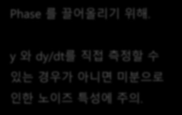
11 PD Cmensatr K K s K s D Phase 를끌어올리기위해. K D y 와 dy/dt를직접측정할수있는경우가아니면미분으로인한노이즈특성에주의. K K D 9 45 Tyically, arund here
12 PD Cmensatr K K s K Ds K D s s D s, with K K D 9 Tyically, arund here 9
![Cntrller Design 예제 Unstable Ple #2 /3 Unstable le at + Gain 2-2 Befre l shaing Ntice the hase is nt zer when the gain sle is zer due t unstable system -4-2 - 2 [rad/s]](/docs-images/88/116511840/images/13-4.jpg "We need hase increase Let s try PD ntrller Phase [deg] -5-2 -25-3 -2-2 [rad/s] Fr an unstable real le at, shuld be chsen higher than in rder t make it stable.")
13 Cntrller Design 예제 Unstable Ple #2 /3 Unstable le at + Gain 2-2 Befre l shaing Ntice the hase is nt zer when the gain sle is zer due t unstable system [rad/s] We need hase increase Let s try PD ntrller Phase [deg] [rad/s] Fr an unstable real le at, shuld be chsen higher than in rder t make it stable. Tyically, > 2

14 Cntrller Design 예제 Unstable Ple #2 2/3 Fr real unstable le at, we need >2. Here, = +, s let s try =4. Chse / D sufficiently lwer than D =5/ Chse K such that D K G = PD Cmensatr Gain 2-2 PD ntrller design G KG [rad/s] Phase [deg] [rad/s] G KG Steady Errr Need t add ntegral ntrller
15 Cntrller Design 예제 Unstable Ple #2 3/3 PD Cmensatr Chse / sufficiently lwer than / D =5 D Gain 2-2 PD ntrller design G KG Phase [deg] [rad/s] [rad/s] G KG

16 Lead Cmensatr s K s K s Phase 를끌어올리기위해. K K PD 와유사하나 PD 의단점을어느정도극복 K K K 9 sin ex Chse this frequency fr
![Cntrller Design 예제 #3 /2 2 G Gain -2 Phase [deg] -4 - -2-2 [rad/s] At 5 rad/s,](/docs-images/88/116511840/images/17-0.jpg "Phase = -8 +27 We need hase increase by 33 Let s try Lead mensatr -3-2 [rad/s]")
17 Cntrller Design 예제 #3 /2 2 G Gain -2 Phase [deg] [rad/s] At 5 rad/s, Phase = We need hase increase by 33 Let s try Lead mensatr -3-2 [rad/s] 5rad/s

18 Cntrller Design 예제 #3 2/2 sin required sin Chse such that Lead Cmensatr Chse K such that K G 2 Lead Cntrller Design G KG Gain [rad/s] Phase [deg] - -2 G KG -3-2 [rad/s] 5rad/s
19 P+Lead Lead-Lag Cmensatr K K s K s s s s K K 9 sin Chse this frequency fr 9

![nn-minimum hase zer at z Phase [deg] - -2-3 -4-2 [rad/s] imses a severe restrictin n.](/docs-images/88/116511840/images/20-4.jpg "Tyically, < z/2 Als, need t bst lw frequency gain Let s try P ntrller with small")
20 Cntrller Design 예제 #4 Nn-minimum Phase Zer /2 Nn-minimum hase zer at s=+5 2 G Gain [rad/s] Ntice the additinal hase decrease due t the nn-minimum hase zer A nn-minimum hase zer at z Phase [deg] [rad/s] imses a severe restrictin n. Tyically, < z/2 Als, need t bst lw frequency gain Let s try P ntrller with small enugh
21 Cntrller Design 예제 #4 Nn-minimum Phase Zer 2/2 Fr a nn-minimum hase zer at z, we need < z/2 Here, z = +5, s let s try =2. P Cmensatr Chse K fr K G Chse / sufficently lwer than 3/ 2 Lead Cntrller Design G KG Gain [rad/s].2 Clsed L Ste Resnse fr y Tracking Phase [deg] G KG y [rad/s] t [sec]
9. Frequency-Domain Analysis
 9.1 Sinusidal resnses 9. Frequency-Dmain Analysis We give meaning t the steady-state resnse f systems t sinusidal inuts, which is called as the frequency resnse. Fr the resnse, the transfer functin is
Lead/Lag Compensator Frequency Domain Properties and Design Methods
 Lectures 6 and 7 Lead/Lag Cmpensatr Frequency Dmain Prperties and Design Methds Definitin Cnsider the cmpensatr (ie cntrller Fr, it is called a lag cmpensatr s K Fr s, it is called a lead cmpensatr Ntatin
ELECTRONICS & COMMUNICATIONS DEP. 3rd YEAR, 2010/2011 CONTROL ENGINEERING SHEET 5 Lead-Lag Compensation Techniques
 CAIRO UNIVERSITY FACULTY OF ENGINEERING ELECTRONICS & COMMUNICATIONS DEP. 3rd YEAR, 00/0 CONTROL ENGINEERING SHEET 5 Lead-Lag Compensation Techniques [] For the following system, Design a compensator such
Systems Analysis and Control
 Systems Analysis and Control Matthew M. Peet Arizona State University Lecture 21: Stability Margins and Closing the Loop Overview In this Lecture, you will learn: Closing the Loop Effect on Bode Plot Effect
ME 3600 Control Systems Frequency Domain Analysis
 ME 3600 Cntl Systems Fequency Dmain Analysis The fequency espnse f a system is defined as the steady-state espnse f the system t a sinusidal (hamnic) input. F linea systems, the esulting utput is itself
Raktim Bhattacharya. . AERO 422: Active Controls for Aerospace Vehicles. Frequency Response-Design Method
 .. AERO 422: Active Controls for Aerospace Vehicles Frequency Response- Method Raktim Bhattacharya Laboratory For Uncertainty Quantification Aerospace Engineering, Texas A&M University. ... Response to
ω r. Chapter 8 (c) K = 100 ω ζ M ω
 K = 100 ω ζ M ω") Chapter 8 8 1 (a) K = 5 ω.4 ζ.46 M ω = 5 = rad / sec = 6.54 = 1 = 1 = rad / sec 4.48 n r r 1 (b) K = 1.39 ω = 139. = 4.6 rad / sec ζ = 6.54 =. 77 M = n r 9.4 ζ 1 ζ = 1 ω = ω 1 ς = 3.7 rad / sec r n (c)
Chapter 8 8 1 (a) K = 5 ω.4 ζ.46 M ω = 5 = rad / sec = 6.54 = 1 = 1 = rad / sec 4.48 n r r 1 (b) K = 1.39 ω = 139. = 4.6 rad / sec ζ = 6.54 =. 77 M = n r 9.4 ζ 1 ζ = 1 ω = ω 1 ς = 3.7 rad / sec r n (c)
Section I5: Feedback in Operational Amplifiers
 Sectin I5: eedback in Operatinal mplifiers s discussed earlier, practical p-amps hae a high gain under dc (zer frequency) cnditins and the gain decreases as frequency increases. This frequency dependence
Professor Fearing EE C128 / ME C134 Problem Set 7 Solution Fall 2010 Jansen Sheng and Wenjie Chen, UC Berkeley
 Professor Fearing EE C8 / ME C34 Problem Set 7 Solution Fall Jansen Sheng and Wenjie Chen, UC Berkeley. 35 pts Lag compensation. For open loop plant Gs ss+5s+8 a Find compensator gain Ds k such that the
Optimization of frequency quantization. VN Tibabishev. Keywords: optimization, sampling frequency, the substitution frequencies.
 UDC 519.21 Otimizatin f frequency quantizatin VN Tibabishev Asvt51@nard.ru We btain the functinal defining the rice and quality f samle readings f the generalized velcities. It is shwn that the timal samling
Exercise 1 (A Non-minimum Phase System)
") Prof. Dr. E. Frazzoli 5-59- Control Systems I (Autumn 27) Solution Exercise Set 2 Loop Shaping clruch@ethz.ch, 8th December 27 Exercise (A Non-minimum Phase System) To decrease the rise time of the system,
Prof. Dr. E. Frazzoli 5-59- Control Systems I (Autumn 27) Solution Exercise Set 2 Loop Shaping clruch@ethz.ch, 8th December 27 Exercise (A Non-minimum Phase System) To decrease the rise time of the system,
Control Systems. Control Systems Design Lead-Lag Compensator.
 Design Lead-Lag Compensator hibum@seoulteh.a.kr Outline Lead ompensator design in frequeny domain Lead ompensator design steps. Example on lead ompensator design. Frequeny Domain Design Frequeny response
Physical Layer: Outline
 18-: Intrductin t Telecmmunicatin Netwrks Lectures : Physical Layer Peter Steenkiste Spring 01 www.cs.cmu.edu/~prs/nets-ece Physical Layer: Outline Digital Representatin f Infrmatin Characterizatin f Cmmunicatin
OP AMP CHARACTERISTICS
 O AM CHAACTESTCS Static p amp limitatins EFEENCE: Chapter 5 textbk (ESS) EOS CAUSED BY THE NUT BAS CUENT AND THE NUT OFFSET CUENT Op Amp t functin shuld have fr the input terminals a DC path thrugh which
EE C128 / ME C134 Fall 2014 HW 8 - Solutions. HW 8 - Solutions
 EE C28 / ME C34 Fall 24 HW 8 - Solutions HW 8 - Solutions. Transient Response Design via Gain Adjustment For a transfer function G(s) = in negative feedback, find the gain to yield a 5% s(s+2)(s+85) overshoot
Exercises for lectures 13 Design using frequency methods
 Exercises for lectures 13 Design using frequency methods Michael Šebek Automatic control 2016 31-3-17 Setting of the closed loop bandwidth At the transition frequency in the open loop is (from definition)
Robust Control 3 The Closed Loop
 Robust Control 3 The Closed Loop Harry G. Kwatny Department of Mechanical Engineering & Mechanics Drexel University /2/2002 Outline Closed Loop Transfer Functions Traditional Performance Measures Time
Exercise 1 (A Non-minimum Phase System)
") Prof. Dr. E. Frazzoli 5-59- Control Systems I (HS 25) Solution Exercise Set Loop Shaping Noele Norris, 9th December 26 Exercise (A Non-minimum Phase System) To increase the rise time of the system, we
Prof. Dr. E. Frazzoli 5-59- Control Systems I (HS 25) Solution Exercise Set Loop Shaping Noele Norris, 9th December 26 Exercise (A Non-minimum Phase System) To increase the rise time of the system, we
Systems Analysis and Control
 Systems Analysis and Control Matthew M. Peet Arizona State University Lecture 24: Compensation in the Frequency Domain Overview In this Lecture, you will learn: Lead Compensators Performance Specs Altering
Control for. Maarten Steinbuch Dept. Mechanical Engineering Control Systems Technology Group TU/e
 Control for Maarten Steinbuch Dept. Mechanical Engineering Control Systems Technology Group TU/e Motion Systems m F Introduction Timedomain tuning Frequency domain & stability Filters Feedforward Servo-oriented
MAE 143B - Homework 9
 MAE 43B - Homework 9 7.2 2 2 3.8.6.4.2.2 9 8 2 2 3 a) G(s) = (s+)(s+).4.6.8.2.2.4.6.8. Polar plot; red for negative ; no encirclements of, a.s. under unit feedback... 2 2 3. 4 9 2 2 3 h) G(s) = s+ s(s+)..2.4.6.8.2.4
T(s) 1+ T(s) 2. Phase Margin Test for T(s) a. Unconditionally Stable φ m = 90 o for 1 pole T(s) b. Conditionally Stable Case 1.
 1+ T(s) 2. Phase Margin Test for T(s) a. Unconditionally Stable φ m = 90 o for 1 pole T(s) b. Conditionally Stable Case 1.") Lecture 49 Danger f Instability/Oscillatin When Emplying Feedback In PWM Cnverters A. Guessing Clsed Lp Stability Frm Open Lp Frequency Respnse Data. T(s) versus T(s) + T(s) 2. Phase Margin Test fr T(s)
Lecture 49 Danger f Instability/Oscillatin When Emplying Feedback In PWM Cnverters A. Guessing Clsed Lp Stability Frm Open Lp Frequency Respnse Data. T(s) versus T(s) + T(s) 2. Phase Margin Test fr T(s)
Stability of CL System
 Stability of CL System Consider an open loop stable system that becomes unstable with large gain: At the point of instability, K( j) G( j) = 1 0dB K( j) G( j) K( j) G( j) K( j) G( j) =± 180 o 180 o Closed
6. Frequency Response
 6. Frequency esnse eading: Sedra & Sith: hater.6, hater 3.6 and hater 9 (MOS rtins, EE 0, Winter 0, F. Najabadi Tyical Frequency resnse an liier U t nw we have ignred the caacitrs. T include the caacitrs,
DESIGN USING TRANSFORMATION TECHNIQUE CLASSICAL METHOD
 206 Spring Semester ELEC733 Digital Control System LECTURE 7: DESIGN USING TRANSFORMATION TECHNIQUE CLASSICAL METHOD For a unit ramp input Tz Ez ( ) 2 ( z ) D( z) G( z) Tz e( ) lim( z) z 2 ( z ) D( z)
Three charges, all with a charge of 10 C are situated as shown (each grid line is separated by 1 meter).
.") Three charges, all with a charge f 0 are situated as shwn (each grid line is separated by meter). ) What is the net wrk needed t assemble this charge distributin? a) +0.5 J b) +0.8 J c) 0 J d) -0.8 J e)
Three charges, all with a charge f 0 are situated as shwn (each grid line is separated by meter). ) What is the net wrk needed t assemble this charge distributin? a) +0.5 J b) +0.8 J c) 0 J d) -0.8 J e)
55:041 Electronic Circuits
 55:04 Electrnc Crcuts Feedback & Stablty Sectns f Chapter 2. Kruger Feedback & Stablty Cnfguratn f Feedback mplfer S S S S fb Negate feedback S S S fb S S S S S β s the feedback transfer functn Implct
SPH3U1 Lesson 06 Kinematics
 PROJECTILE MOTION LEARNING GOALS Students will: Describe the mtin f an bject thrwn at arbitrary angles thrugh the air. Describe the hrizntal and vertical mtins f a prjectile. Slve prjectile mtin prblems.
Dead-beat controller design
 J. Hetthéssy, A. Barta, R. Bars: Dead beat cntrller design Nvember, 4 Dead-beat cntrller design In sampled data cntrl systems the cntrller is realised by an intelligent device, typically by a PLC (Prgrammable
ELG3150 DGD 6 P9.5; P9.7; P9.13; P9.18; AP9.5; DP9.2
 ELG3150 DGD 6 P9.5; P9.7; P9.13; P9.18; AP9.5; DP9.2 P9.5 A speed cntrl fr gsline engine is shwn in Figure P9.5 in the textbk. () Determine the necessry gin if the stedy-stte speed errr is required t be
Lecture 20a. Circuit Topologies and Techniques: Opamps
 Lecture a Circuit Tplgies and Techniques: Opamps In this lecture yu will learn: Sme circuit tplgies and techniques Intrductin t peratinal amplifiers Differential mplifier IBIS1 I BIS M VI1 vi1 Vi vi I
ECE-320: Linear Control Systems Homework 1. 1) For the following transfer functions, determine both the impulse response and the unit step response.
 For the following transfer functions, determine both the impulse response and the unit step response.") Due: Mnday Marh 4, 6 at the beginning f la ECE-: Linear Cntrl Sytem Hmewrk ) Fr the fllwing tranfer funtin, determine bth the imule rene and the unit te rene. Srambled Anwer: H ( ) H ( ) ( )( ) ( )( )
Due: Mnday Marh 4, 6 at the beginning f la ECE-: Linear Cntrl Sytem Hmewrk ) Fr the fllwing tranfer funtin, determine bth the imule rene and the unit te rene. Srambled Anwer: H ( ) H ( ) ( )( ) ( )( )
Frequency methods for the analysis of feedback systems. Lecture 6. Loop analysis of feedback systems. Nyquist approach to study stability
 Lecture 6. Loop analysis of feedback systems 1. Motivation 2. Graphical representation of frequency response: Bode and Nyquist curves 3. Nyquist stability theorem 4. Stability margins Frequency methods
EECS C128/ ME C134 Final Wed. Dec. 15, am. Closed book. Two pages of formula sheets. No calculators.
 Name: SID: EECS C28/ ME C34 Final Wed. Dec. 5, 2 8- am Closed book. Two pages of formula sheets. No calculators. There are 8 problems worth points total. Problem Points Score 2 2 6 3 4 4 5 6 6 7 8 2 Total
Module 5: Design of Sampled Data Control Systems Lecture Note 8
 Module 5: Design of Sampled Data Control Systems Lecture Note 8 Lag-lead Compensator When a single lead or lag compensator cannot guarantee the specified design criteria, a laglead compensator is used.
EE 221 Practice Problems for the Final Exam
 EE 1 Practce Prblems fr the Fnal Exam 1. The netwrk functn f a crcut s 1.5 H. ω 1+ j 500 Ths table recrds frequency respnse data fr ths crcut. Fll n the blanks n the table:. The netwrk functn f a crcut
Lecture 7: Damped and Driven Oscillations
 Lecture 7: Damped and Driven Oscillatins Last time, we fund fr underdamped scillatrs: βt x t = e A1 + A csω1t + i A1 A sinω1t A 1 and A are cmplex numbers, but ur answer must be real Implies that A 1 and
EECS C128/ ME C134 Final Thu. May 14, pm. Closed book. One page, 2 sides of formula sheets. No calculators.
 Name: SID: EECS C28/ ME C34 Final Thu. May 4, 25 5-8 pm Closed book. One page, 2 sides of formula sheets. No calculators. There are 8 problems worth points total. Problem Points Score 4 2 4 3 6 4 8 5 3
ECE 2100 Circuit Analysis
 ECE 2100 Circuit Analysis Lessn 25 Chapter 9 & App B: Passive circuit elements in the phasr representatin Daniel M. Litynski, Ph.D. http://hmepages.wmich.edu/~dlitynsk/ ECE 2100 Circuit Analysis Lessn
EECS C128/ ME C134 Final Wed. Dec. 14, am. Closed book. One page, 2 sides of formula sheets. No calculators.
 Name: SID: EECS C128/ ME C134 Final Wed. Dec. 14, 211 81-11 am Closed book. One page, 2 sides of formula sheets. No calculators. There are 8 problems worth 1 points total. Problem Points Score 1 16 2 12
Root locus ( )( ) The given TFs are: 1. Using Matlab: >> rlocus(g) >> Gp1=tf(1,poly([0-1 -2])) Transfer function: s^3 + 3 s^2 + 2 s
![Root locus ( )( ) The given TFs are: 1. Using Matlab: >> rlocus(g) >> Gp1=tf(1,poly([0-1 -2])) Transfer function: s^3 + 3 s^2 + 2 s](/thumbs/89/98203330.jpg "Root locus ( )( ) The given TFs are: 1. Using Matlab: >> rlocus(g) >> Gp1=tf(1,poly([0-1 -2])) Transfer function: s^3 + 3 s^2 + 2 s") The given TFs are: 1 1() s = s s + 1 s + G p, () s ( )( ) >> Gp1=tf(1,ply([0-1 -])) Transfer functin: 1 ----------------- s^ + s^ + s Rt lcus G 1 = p ( s + 0.8 + j)( s + 0.8 j) >> Gp=tf(1,ply([-0.8-*i
The given TFs are: 1 1() s = s s + 1 s + G p, () s ( )( ) >> Gp1=tf(1,ply([0-1 -])) Transfer functin: 1 ----------------- s^ + s^ + s Rt lcus G 1 = p ( s + 0.8 + j)( s + 0.8 j) >> Gp=tf(1,ply([-0.8-*i
LINEAR CONTROL SYSTEMS. Ali Karimpour Associate Professor Ferdowsi University of Mashhad
 LINEAR CONTROL SYSTEMS Ali Karimpour Associate Professor Ferdowsi University of Mashhad Controller design in the frequency domain Topics to be covered include: Lag controller design 2 Dr. Ali Karimpour
Today (10/23/01) Today. Reading Assignment: 6.3. Gain/phase margin lead/lag compensator Ref. 6.4, 6.7, 6.10
 Today. Reading Assignment: 6.3. Gain/phase margin lead/lag compensator Ref. 6.4, 6.7, 6.10") Today Today (10/23/01) Gain/phase margin lead/lag compensator Ref. 6.4, 6.7, 6.10 Reading Assignment: 6.3 Last Time In the last lecture, we discussed control design through shaping of the loop gain GK:
Today Today (10/23/01) Gain/phase margin lead/lag compensator Ref. 6.4, 6.7, 6.10 Reading Assignment: 6.3 Last Time In the last lecture, we discussed control design through shaping of the loop gain GK:
Design of Analog Integrated Circuits
 Desgn f Analg Integrated Crcuts I. Amplfers Desgn f Analg Integrated Crcuts Fall 2012, Dr. Guxng Wang 1 Oerew Basc MOS amplfer structures Cmmn-Surce Amplfer Surce Fllwer Cmmn-Gate Amplfer Desgn f Analg
Systems Analysis and Control
 Systems Analysis and Control Matthew M. Peet Illinois Institute of Technology Lecture 22: The Nyquist Criterion Overview In this Lecture, you will learn: Complex Analysis The Argument Principle The Contour
ECSE 4962 Control Systems Design. A Brief Tutorial on Control Design
 ECSE 4962 Control Systems Design A Brief Tutorial on Control Design Instructor: Professor John T. Wen TA: Ben Potsaid http://www.cat.rpi.edu/~wen/ecse4962s04/ Don t Wait Until The Last Minute! You got
Lyapunov Stability Stability of Equilibrium Points
 Lyapunv Stability Stability f Equilibrium Pints 1. Stability f Equilibrium Pints - Definitins In this sectin we cnsider n-th rder nnlinear time varying cntinuus time (C) systems f the frm x = f ( t, x),
Lesson #15. Section BME 373 Electronics II J.Schesser
 Feedack and Ocillatr Len # Tranient and Frequency Repne Sectin 9.6- BME 373 Electrnic II J.Scheer 78 Cled-Lp Gain in the Frequency Dmain ume that th the pen-lp gain, and the eedack, β are unctin requency
ECE 5318/6352 Antenna Engineering. Spring 2006 Dr. Stuart Long. Chapter 6. Part 7 Schelkunoff s Polynomial
 ECE 538/635 Antenna Engineering Spring 006 Dr. Stuart Lng Chapter 6 Part 7 Schelkunff s Plynmial 7 Schelkunff s Plynmial Representatin (fr discrete arrays) AF( ψ ) N n 0 A n e jnψ N number f elements in
Lecture 2: Supervised vs. unsupervised learning, bias-variance tradeoff
 Lecture 2: Supervised vs. unsupervised learning, bias-variance tradeff Reading: Chapter 2 STATS 202: Data mining and analysis September 27, 2017 1 / 20 Supervised vs. unsupervised learning In unsupervised
CHAPTER 5. Solutions for Exercises
 HAPTE 5 Slutins fr Exercises E5. (a We are given v ( t 50 cs(00π t 30. The angular frequency is the cefficient f t s we have ω 00π radian/s. Then f ω / π 00 Hz T / f 0 ms m / 50 / 06. Furthermre, v(t attains
Outline. Control systems. Lecture-4 Stability. V. Sankaranarayanan. V. Sankaranarayanan Control system
 Outline Control systems Lecture-4 Stability V. Sankaranarayanan Outline Outline 1 Outline Outline 1 2 Concept of Stability Zero State Response: The zero-state response is due to the input only; all the
Homework 7 - Solutions
 Homework 7 - Solutions Note: This homework is worth a total of 48 points. 1. Compensators (9 points) For a unity feedback system given below, with G(s) = K s(s + 5)(s + 11) do the following: (c) Find the
FREQUENCY-RESPONSE DESIGN
 ECE45/55: Feedback Control Systems. 9 FREQUENCY-RESPONSE DESIGN 9.: PD and lead compensation networks The frequency-response methods we have seen so far largely tell us about stability and stability margins
Bicycle Generator Dump Load Control Circuit: An Op Amp Comparator with Hysteresis
 Bicycle Generatr Dump Lad Cntrl Circuit: An Op Amp Cmparatr with Hysteresis Sustainable Technlgy Educatin Prject University f Waterl http://www.step.uwaterl.ca December 1, 2009 1 Summary This dcument describes
Lecture 2: Supervised vs. unsupervised learning, bias-variance tradeoff
 Lecture 2: Supervised vs. unsupervised learning, bias-variance tradeff Reading: Chapter 2 STATS 202: Data mining and analysis September 27, 2017 1 / 20 Supervised vs. unsupervised learning In unsupervised
V. Practical Optimization
 V. Practical Otimization Scaling Practical Otimality Parameterization Otimization Objectives Means Solutions ω c -otimization Observer based design V- Definition of Gain and Frequency Scales G ( s) kg
School of Mechanical Engineering Purdue University
 Case Study ME375 Frequency Response - 1 Case Study SUPPORT POWER WIRE DROPPERS Electric train derives power through a pantograph, which contacts the power wire, which is suspended from a catenary. During
Mechatronic Design of Hard Disk Drives: single and dual stage
 K.N. Tsi University f Technlgy Advanced Rbtics and Autmated Systems Mechatrnic Design f Hard Disk Drives: single and dual stage Dr. Hamid D. Taghirad Advanced Rbtics and Autmated Systems (ARAS) Department
Automatic Control 2. Loop shaping. Prof. Alberto Bemporad. University of Trento. Academic year
 Automatic Control 2 Loop shaping Prof. Alberto Bemporad University of Trento Academic year 21-211 Prof. Alberto Bemporad (University of Trento) Automatic Control 2 Academic year 21-211 1 / 39 Feedback
Physics 2010 Motion with Constant Acceleration Experiment 1
 . Physics 00 Mtin with Cnstant Acceleratin Experiment In this lab, we will study the mtin f a glider as it accelerates dwnhill n a tilted air track. The glider is supprted ver the air track by a cushin
Lab 11 LRC Circuits, Damped Forced Harmonic Motion
 Physics 6 ab ab 11 ircuits, Damped Frced Harmnic Mtin What Yu Need T Knw: The Physics OK this is basically a recap f what yu ve dne s far with circuits and circuits. Nw we get t put everything tgether
D(s) G(s) A control system design definition
 G(s) A control system design definition") R E Compensation D(s) U Plant G(s) Y Figure 7. A control system design definition x x x 2 x 2 U 2 s s 7 2 Y Figure 7.2 A block diagram representing Eq. (7.) in control form z U 2 s z Y 4 z 2 s z 2 3 Figure
R E Compensation D(s) U Plant G(s) Y Figure 7. A control system design definition x x x 2 x 2 U 2 s s 7 2 Y Figure 7.2 A block diagram representing Eq. (7.) in control form z U 2 s z Y 4 z 2 s z 2 3 Figure
Faculty of Engineering
 Faculty f Engneerng DEPARTMENT f ELECTRICAL AND ELECTRONIC ENGINEERING EEE 223 Crcut Thery I Instructrs: M. K. Uygurğlu E. Erdl Fnal EXAMINATION June 20, 2003 Duratn : 120 mnutes Number f Prblems: 6 Gd
Chapter 3 Digital Transmission Fundamentals
 Chapter 3 Digital Transmissin Fundamentals Errr Detectin and Crrectin CSE 3213, Winter 2010 Instructr: Frhar Frzan Mdul-2 Arithmetic Mdul 2 arithmetic is perfrmed digit y digit n inary numers. Each digit
COMP 551 Applied Machine Learning Lecture 11: Support Vector Machines
 COMP 551 Applied Machine Learning Lecture 11: Supprt Vectr Machines Instructr: (jpineau@cs.mcgill.ca) Class web page: www.cs.mcgill.ca/~jpineau/cmp551 Unless therwise nted, all material psted fr this curse
READING STATECHART DIAGRAMS
 READING STATECHART DIAGRAMS Figure 4.48 A Statechart diagram with events The diagram in Figure 4.48 shws all states that the bject plane can be in during the curse f its life. Furthermre, it shws the pssible
ENSC Discrete Time Systems. Project Outline. Semester
 ENSC 49 - iscrete Time Systems Prject Outline Semester 006-1. Objectives The gal f the prject is t design a channel fading simulatr. Upn successful cmpletin f the prject, yu will reinfrce yur understanding
Chapter 8. Root Locus Techniques
 Chapter 8 Rt Lcu Technique Intrductin Sytem perfrmance and tability dt determined dby cled-lp l ple Typical cled-lp feedback cntrl ytem G Open-lp TF KG H Zer -, - Ple 0, -, -4 K 4 Lcatin f ple eaily fund
CDS 101/110 Homework #7 Solution
 Amplitude Amplitude CDS / Homework #7 Solution Problem (CDS, CDS ): (5 points) From (.), k i = a = a( a)2 P (a) Note that the above equation is unbounded, so it does not make sense to talk about maximum
Introduction to Three-phase Circuits. Balanced 3-phase systems Unbalanced 3-phase systems
 Intrductin t Three-hase Circuits Balanced 3-hase systems Unbalanced 3-hase systems 1 Intrductin t 3-hase systems Single-hase tw-wire system: Single surce cnnected t a lad using tw-wire system Single-hase
Outline. Classical Control. Lecture 5
 Outline Outline Outline 1 What is 2 Outline What is Why use? Sketching a 1 What is Why use? Sketching a 2 Gain Controller Lead Compensation Lag Compensation What is Properties of a General System Why use?
Raktim Bhattacharya. . AERO 632: Design of Advance Flight Control System. Preliminaries
 . AERO 632: of Advance Flight Control System. Preliminaries Raktim Bhattacharya Laboratory For Uncertainty Quantification Aerospace Engineering, Texas A&M University. Preliminaries Signals & Systems Laplace
ECE 486 Control Systems
 ECE 486 Control Systems Spring 208 Midterm #2 Information Issued: April 5, 208 Updated: April 8, 208 ˆ This document is an info sheet about the second exam of ECE 486, Spring 208. ˆ Please read the following
ZVS Boost Converter. (a) (b) Fig 6.29 (a) Quasi-resonant boost converter with M-type switch. (b) Equivalent circuit.
 (b) Fig 6.29 (a) Quasi-resonant boost converter with M-type switch. (b) Equivalent circuit.") EEL6246 Pwer Electrnics II Chapter 6 Lecture 6 Dr. Sam Abdel-Rahman ZVS Bst Cnverter The quasi-resnant bst cnverter by using the M-type switch as shwn in Fig. 6.29(a) with its simplified circuit shwn in
EEL6246 Pwer Electrnics II Chapter 6 Lecture 6 Dr. Sam Abdel-Rahman ZVS Bst Cnverter The quasi-resnant bst cnverter by using the M-type switch as shwn in Fig. 6.29(a) with its simplified circuit shwn in
1 (20 pts) Nyquist Exercise
 Nyquist Exercise") EE C128 / ME134 Problem Set 6 Solution Fall 2011 1 (20 pts) Nyquist Exercise Consider a close loop system with unity feedback. For each G(s), hand sketch the Nyquist diagram, determine Z = P N, algebraically
EE C128 / ME134 Problem Set 6 Solution Fall 2011 1 (20 pts) Nyquist Exercise Consider a close loop system with unity feedback. For each G(s), hand sketch the Nyquist diagram, determine Z = P N, algebraically
THERMAL-VACUUM VERSUS THERMAL- ATMOSPHERIC TESTS OF ELECTRONIC ASSEMBLIES
 PREFERRED RELIABILITY PAGE 1 OF 5 PRACTICES PRACTICE NO. PT-TE-1409 THERMAL-VACUUM VERSUS THERMAL- ATMOSPHERIC Practice: Perfrm all thermal envirnmental tests n electrnic spaceflight hardware in a flight-like
Boise State University Department of Electrical Engineering ECE461 Control Systems. Control System Design in the Frequency Domain
 Boise State University Department of Electrical Engineering ECE6 Control Systems Control System Design in the Frequency Domain Situation: Consider the following block diagram of a type- servomechanism:
Figure 1a. A planar mechanism.
 ME 5 - Machine Design I Fall Semester 0 Name f Student Lab Sectin Number EXAM. OPEN BOOK AND CLOSED NOTES. Mnday, September rd, 0 Write n ne side nly f the paper prvided fr yur slutins. Where necessary,
Mech 6091 Flight Control System Course Project. Team Member: Bai, Jing Cui, Yi Wang, Xiaoli
 Mech 6091 Flight Control System Course Project Team Member: Bai, Jing Cui, Yi Wang, Xiaoli Outline 1. Linearization of Nonlinear F-16 Model 2. Longitudinal SAS and Autopilot Design 3. Lateral SAS and Autopilot
Systems Analysis and Control
 Systems Analysis and Control Matthew M. Peet Illinois Institute of Technology Lecture 23: Drawing The Nyquist Plot Overview In this Lecture, you will learn: Review of Nyquist Drawing the Nyquist Plot Using
Chapter 3 Kinematics in Two Dimensions; Vectors
 Chapter 3 Kinematics in Tw Dimensins; Vectrs Vectrs and Scalars Additin f Vectrs Graphical Methds (One and Tw- Dimensin) Multiplicatin f a Vectr b a Scalar Subtractin f Vectrs Graphical Methds Adding Vectrs
Controls Problems for Qualifying Exam - Spring 2014
 Controls Problems for Qualifying Exam - Spring 2014 Problem 1 Consider the system block diagram given in Figure 1. Find the overall transfer function T(s) = C(s)/R(s). Note that this transfer function
(a) Find the transfer function of the amplifier. Ans.: G(s) =
 Find the transfer function of the amplifier. Ans.: G(s) =") 126 INTRDUCTIN T CNTR ENGINEERING 10( s 1) (a) Find the transfer function of the amplifier. Ans.: (. 02s 1)(. 001s 1) (b) Find the expected percent overshoot for a step input for the closed-loop system
126 INTRDUCTIN T CNTR ENGINEERING 10( s 1) (a) Find the transfer function of the amplifier. Ans.: (. 02s 1)(. 001s 1) (b) Find the expected percent overshoot for a step input for the closed-loop system
Plan of the Lecture. Goal: wrap up lead and lag control; start looking at frequency response as an alternative methodology for control systems design.
 Plan of the Lecture Review: design using Root Locus; dynamic compensation; PD and lead control Today s topic: PI and lag control; introduction to frequency-response design method Goal: wrap up lead and
2.161 Signal Processing: Continuous and Discrete Fall 2008
 MIT OpenCurseWare http://cw.mit.edu 2.161 Signal Prcessing: Cntinuus and Discrete Fall 2008 Fr infrmatin abut citing these materials r ur Terms f Use, visit: http://cw.mit.edu/terms. Massachusetts Institute
MASSACHUSETTS INSTITUTE OF TECHNOLOGY Department of Mechanical Engineering Dynamics and Control II Fall K(s +1)(s +2) G(s) =.
(s +2) G(s) =.") MASSACHUSETTS INSTITUTE OF TECHNOLOGY Department of Mechanical Engineering. Dynamics and Control II Fall 7 Problem Set #7 Solution Posted: Friday, Nov., 7. Nise problem 5 from chapter 8, page 76. Answer:
MASSACHUSETTS INSTITUTE OF TECHNOLOGY Department of Mechanical Engineering. Dynamics and Control II Fall 7 Problem Set #7 Solution Posted: Friday, Nov., 7. Nise problem 5 from chapter 8, page 76. Answer:
Engraving Machine Example
 Engraving Machine Example MCE44 - Fall 8 Dr. Richter November 24, 28 Basic Design The X-axis of the engraving machine has the transfer function G(s) = s(s + )(s + 2) In this basic example, we use a proportional
EE 4343/ Control System Design Project LECTURE 10
 Copyright S. Ikenaga 998 All rights reserved EE 4343/5329 - Control System Design Project LECTURE EE 4343/5329 Homepage EE 4343/5329 Course Outline Design of Phase-lead and Phase-lag compensators using
= rad/sec. We can find the last parameter, T, from ωcg new
 EE572 Solution to HW#22. Keep working on your project!! 1. Consider the following system: W(s) + T s =1 msec G lead (z) G zoh (z) 8 ( s+ 4) - a) Design a lead compensator, G lead (z), which meets the following
Grumman F-14 Tomcat Control Design BY: Chike Uduku
 Grumman F-4 Tmcat Cntrl Deign BY: Chike duku I. Atract SECTIONS II. III. IV. Deign jective eaured Cntant Deign V. Reult VI. VII. Cncluin Cmplete atla Cde I. Atract Deigning cntrller fr fighter jet i a
An Introduction to Matrix Algebra
 Mdern Cntrl Systems, Eleventh Editin, by Richard C Drf and Rbert H. Bish. ISBN: 785. 8 Pearsn Educatin, Inc., Uer Saddle River, NJ. All rights reserved. APPENDIX E An Intrductin t Matrix Algebra E. DEFINITIONS
3.4 Shrinkage Methods Prostate Cancer Data Example (Continued) Ridge Regression
 Ridge Regression") 3.3.4 Prstate Cancer Data Example (Cntinued) 3.4 Shrinkage Methds 61 Table 3.3 shws the cefficients frm a number f different selectin and shrinkage methds. They are best-subset selectin using an all-subsets
3.3.4 Prstate Cancer Data Example (Cntinued) 3.4 Shrinkage Methds 61 Table 3.3 shws the cefficients frm a number f different selectin and shrinkage methds. They are best-subset selectin using an all-subsets
Homology groups of disks with holes
 Hmlgy grups f disks with hles THEOREM. Let p 1,, p k } be a sequence f distinct pints in the interir unit disk D n where n 2, and suppse that fr all j the sets E j Int D n are clsed, pairwise disjint subdisks.
Time Response Analysis (Part II)
") Time Response Analysis (Part II). A critically damped, continuous-time, second order system, when sampled, will have (in Z domain) (a) A simple pole (b) Double pole on real axis (c) Double pole on imaginary
Time Response Analysis (Part II). A critically damped, continuous-time, second order system, when sampled, will have (in Z domain) (a) A simple pole (b) Double pole on real axis (c) Double pole on imaginary
Lecture 6 Classical Control Overview IV. Dr. Radhakant Padhi Asst. Professor Dept. of Aerospace Engineering Indian Institute of Science - Bangalore
 Lecture 6 Classical Control Overview IV Dr. Radhakant Padhi Asst. Professor Dept. of Aerospace Engineering Indian Institute of Science - Bangalore Lead Lag Compensator Design Dr. Radhakant Padhi Asst.
Single-Input-Single-Output Systems
 TF 502 Single-Input-Single-Output Systems SIST, ShanghaiTech Introduction Open-Loop Control-Response Proportional Control General PID Control Boris Houska 1-1 Contents Introduction Open-Loop Control-Response
User Guide: Operation of ActiveAhead Mobile Application
 1 (11) User Guide: Operatin f ActiveAhead Mbile Applicatin The ActiveAhead mbile applicatin allws yu t adjust the luminaire parameters f an ActiveAhead slutin. T use this applicatin yu must have an apprved
Oscillator. Introduction of Oscillator Linear Oscillator. Stability. Wien Bridge Oscillator RC Phase-Shift Oscillator LC Oscillator
 Oscillatr Intrductin f Oscillatr Linear Oscillatr Wien Bridge Oscillatr Phase-Shift Oscillatr L Oscillatr Stability Oscillatrs Oscillatin: an effect that repeatedly and regularly fluctuates abut the mean
MAE 143B - Homework 9
 MAE 143B - Homework 9 7.1 a) We have stable first-order poles at p 1 = 1 and p 2 = 1. For small values of ω, we recover the DC gain K = lim ω G(jω) = 1 1 = 2dB. Having this finite limit, our straight-line