RANS-SLFM and LES-SLFM numerical simulations of turbulent non-premixed oxy-fuel jet flames using CO2/O2 mixture
|
|
|
- Emma Imogen Cummings
- 5 years ago
- Views:
Transcription

1 Graduate Theses and Dissertations Iowa State University Capstones, Theses and Dissertations 217 RANS-SLFM and LES-SLFM numerical simulations of turbulent non-premixed oxy-fuel jet flames using CO2/O2 mixture Adel Alghamdi Iowa State University Follow this and additional works at: Part of the Chemical Engineering Commons Recommended Citation Alghamdi, Adel, "RANS-SLFM and LES-SLFM numerical simulations of turbulent non-premixed oxy-fuel jet flames using CO2/O2 mixture" (217). Graduate Theses and Dissertations This Thesis is brought to you for free and open access by the Iowa State University Capstones, Theses and Dissertations at Iowa State University Digital Repository. It has been accepted for inclusion in Graduate Theses and Dissertations by an authorized administrator of Iowa State University Digital Repository. For more information, please contact
2 RANS-SLFM and LES-SLFM numerical simulations of turbulent non-premixed oxy-fuel jet flames using CO2/O2 mixture by Adel Alghamdi A thesis submitted to the graduate faculty in partial fulfillment of the requirements for the degree of MASTER OF SCIENCE Major: Chemical Engineering Program of Study Committee: Rodney O. Fox, Major Professor Alberto Passalacqua Dennis Vigil Iowa State University Ames, Iowa 217 Copyright Adel Alghamdi, 217. All rights reserved.
3 ii TABLE OF CONTENTS ACKNOWLEDGMENTS... iv ABSTRACT... vi CHAPTER 1. INTRODUCTION AND OVERVIEW Goals and Motivation Organization... 2 CHAPTER 2. BACKGROUND AND LITERATURE REVIEW Non-Premixed Turbulent Combustion Sandia/TUD piloted CH4/Air Jet Flame Oxy-Fuel Jet Flames... 7 CHAPTER 3. THEORY AND GOVERNING EQUATIONS Reynolds Averaged Navier- Stokes (RANS) Conserved scalar: Mixture Fraction Large Eddy Simulation (LES) Closure Model Steady Laminar Flamelet Model (SLFM) Flamelets Governing Equations Presumed Shape PDF Generation of flamelet library CHAPTER 4. RANS SIMULATION DETAILS Sandia D-Flame Simulation Setup Oxy-fuel B-1 Flame Simulation Setup RANS Results Sandia D-Flame Results Oxy-fuel B-1 Results Conclusion... 41
4 iii CHAPTER 5. LES SIMULATION DETAILS LES/SLFM for Sandia D Flame Simulation Setup for B-1 Flame Computational Domain and Grid Boundary Conditions Results and Discussion The Influence of Scalar Dissipation Rate LES/SLFM for B-3 Flame Conclusion and Future work REFERENCES... 6 APPENDIX A ADDITIONAL RANS RESULTS FOR SANDIA D FLAME APPENDIX B ADDITIONAL RANS RESULTS FOR B-1 FLAME APPENDIX C ADDITIONAL LES RESULTS FOR B-1 FLAME... 69
5 iv ACKNOWLEDGMENTS The financial support for this work was provided by Saudi Arabia Basic Industries Corporation (SABIC). The research calculations were conducted using Iowa State University (ISU) HPC resources. In addition, this work was conducted with the collaborations with Dr. Raman group at University of Michigan (UMICH) at the aerospace department. I would like to express my gratefulness and heartfelt thanks to many people who helped me throughout the course of this research, in particular: Graduate students and postdoctoral fellows: Special thanks to Malik Hassanaly (UMICH), for sharing and debugging the code umflameletfoam, also for his valuable discussions and inputs throughout the course of this project. Yihao Tang (UMICH), for his help on constructing the flamelet library using FlameMaster. In addition, I would like to acknowledge the great support I received from Dr. Bo Kong (ISU) and Dr. Xiaofei Hu (ISU) with OpenFoam related issues. Finally, Dr. Zhenping Liu (ISU) and Michael Baker (ISU) for their helpful discussions about turbulence and reactive flow modeling and simulations. Committee members and SABIC management: I would like to express my gratitude to my advisor Dr. Rodney O. Fox for providing the opportunity to pursue my Ms. degree. Through the course of my research, Dr. Fox has been very supportive and has spent all the time required to carefully guide me toward the completion of this work. On the other hand, I would especially like to thank, Dr. Venkat Raman for giving me the opportunity to work in close collaboration with his group. My research has benefited greatly from Dr. Venkat Raman feedback and suggestions. Besides, I would like to thank Dr. Alberto
6 v Passalacqua and Dr. Dennis Vigil for serving as my committee members and for their valuable feedback on this project. I would like to extend my gratefulness to SABIC management, specifically Dr. Ramsey Bunama who supported me to get the approval for pursuing my higher education at ISU through SABIC scholarship program. Dr. Bunama has passed away the 16th February of 217, during this project, and it wouldn t be possible to succeed without his tremendous support and guidance. The authors are also grateful to Dr. Pannala Sreekanth and David West for initiating this project, and for their valuable feedback and suggestions during the course of this project.
7 vi ABSTRACT The focus of this work was to study the structure of multiple turbulent flame configurations using the steady laminar flamelet model (SLFM) coupled with Reynolds-averaged Navier-Stokes (RANS) and large eddy simulation (LES) transport equations. A detailed chemistry mechanism (GRI 3.) was used in the formulation of the flamelet library. In addition, a probability density function (PDF) approach was used to generate the flamelet table in terms of its mean quantities as a function of the Favre-averaged mixture fraction, mixture fraction variance, and 2 ( ZZ,, ) the scalar dissipation rate. A beta PDF was assumed for mixture fraction and a delta function distribution for the scalar dissipation rate. This approach ensured that finite-rate chemistry effects were introduced in the turbulent flow calculations. Radial mean and RMS distributions of temperature, mixture fraction, and species mass fractions were predicted at different axial locations for Sandia D and B-1 flames. The simulation results were validated against experimental data (Barlow & Frank 27; Sevault et al. 212). The validation study showed that LES/SFLM has better mean and RMS distributions for the B1 flame compared to RANS-SLFM. This was due to the fact that LES has a better representation of mixing than RANS since it resolves the large turbulent scales, which contain the largest amount of kinetic energy and control the mixing process in turbulent non-premixed combustion. Nonetheless, RANS-SLFM produced an acceptable mean profile for the Sandia D-flame for relatively low computational expense. However, mean radial profiles of minor species were not accurately predicted for either flame using RANS-SLFM, while good agreement was obtained with LES-SFLM
8 1 CHAPTER 1. INTRODUCTION AND OVERVIEW Turbulent combustion can be classified into premixed and non-premixed combustion. The major difference is the fuel for the non-premixed configuration is fed separately from the oxidizer stream into the combustion chamber where chemical reactions take place. The study will only focus on the non-premixed flames. Turbulent non-premixed combustion is employed in many industrial systems for two main reasons. First, it is relatively easier to design and build burners compared to a premixed configuration where complete mixing is not required. Second, it is much safer to operate at a largescale, such as gas turbines, furnaces, and boilers. Turbulent combustion by nature has complex physics due to the complexity of turbulent flow and the chemical reactions that occur during the combustion process. Thus, strong coupling of both phenomena is a major challenge in the field of computational fluid dynamics (CFD); therefore, there is an interest in using numerical simulation as a research tool to model non-premixed turbulent flames to help improve the energy efficiency of current combustors or testing new technologies. There are three main simulation strategies used in CFD. Reynolds-Averaged Navier- Stokes (RANS), Large Eddy Simulation (LES), and Direct Numerical Simulation (DNS). In RANS and LES, turbulent eddies are not completely resolved, so another model is required to resolve those eddies, while in DNS all turbulent scales are resolved to the Kolmogorov scale. LES has been extensively used in recent years to model the behavior of turbulent non-premixed flames; because LES computational expense stands in the middle between RANS and DNS. In addition, resolving the large scale of the turbulent flow tend to control most of the statistical properties that
9 2 affect the flame structure and chemistry. Furthermore, the level of accuracy that LES can provide predicting the pollutant concentrations which cannot be captured by RANS formulations. Therefore, this study will focus on RANS and LES models coupled with chemistry model to simulate non-premixed flames while DNS will not be included in this study. 1.1 Goals and Motivation One of the primary motives to study oxy-fuel combustion is global warming. First, oxyfuel combustion system uses CO2 as an inert gas with O2 to reduce the adiabatic flame temperature and prevents NOx formations from going into the atmosphere. Second, non-premixed oxy-fuel jet flames are not widely studied in the academic literature. Therefore, in this work, Steady Laminar Flamelet Model (SLFM) was used to simulate Sandia D and oxy-fuel (B1) flames in RANS and LES context with full reaction mechanism GRI 3. to predict both flames structure. Results from RANS/SLFM and LES/SLFM were validated against experimental data published in the academic literature. In addition, this study included the investigation of the effects of scalar dissipation rate and inlet conditions on the structure of B-1 flame. Finally, the proposed models can be used to improve the efficiency of the oxy-fuel combustion mode in general, leading to less production of harmful emissions. 1.2 Organization This work is organized into five chapters. Chapter 1 explored the introduction to nonpremixed combustion, background, and motivation for conducting this research. The other chapters have been organized as follows: Chapter 2: Literature of modeling turbulent non-premixed combustion using RANS and LES approaches has been reviewed. In addition, the chapter includes detailed description of Sandia piloted CH4/air and oxy-fuel CH4/H2 flames, including the experimental setup and measurements.
10 3 Chapter 3: theoretical background, formulations of RANS and LES turbulence modeling have been presented. The coupling of mixture fraction transport equations and the scalar dissipation rate with the turbulence models have been discussed. For RANS approach, k model has been adopted for this work along with the combustion model. The LES approach has been discussed in details including the filtering operations, along with the closure models used for the sub-grid stress and the scalar fluxes. In addition, SLFM formulations have been explained in details, including the PDF presumed shapes for constructing the flamelet tables, and the process flow diagram of SLFM with RANS and LES. Chapter 4: RANS simulation details including the computational domain, grids, and turbulence model parameters for Sandia D and B-1 flames. The results of RANS/SLFM have been presented for both flames and validated against experimental data for the piloted partially premixed Sandia D flame and the non-premixed oxy-fuel B-1 flame. Chapter 5: LES computational domain, grids, and boundary conditions have been presented for simulating Sandia D and B-1 flames. Results from LES/SLFM, have been compared against RANS/SLFM approach and the experimental data for Sandia D and B-1 flames. In addition, the influence of the scalar dissipation rate and the inlet conditions on the flame structure of B-1 flame have been discussed. Finally, the concluding remarks of this research and the proposed future work have been presented.
11 4 CHAPTER 2. BACKGROUND AND LITERATURE REVIEW For turbulent flows, different length scales exist to be either resolved or modeled. In RANS, turbulent flow is modeled as ensemble averaged where all turbulent fluctuation scales are modeled; (3.1)which make it less accurate compared to other approaches but the most affordable computationally. In combustion, the turbulent fluctuation is not statistically homogenous. Therefore, RANS approach faces difficulties predicting important aspects of reactive flows (Pitsch & Steiner 2) & (Pitsch 22a). However, The fundamentals of RANS models can still be used for other modeling techniques explored in the literature by (Wegner et al. 24) (Klimenko & Bilger 1999) (Pope 1985) (Veynante & Vervisch 22). On the other hand, large eddy simulation was first introduced in the 199s to account for some of the drawbacks of RANS approach dealing with turbulent reacting flows. In LES turbulent flow field is spatially filtered and not ensemble averaged which resolves the large scale of turbulent fluctuations that directly affect the mixing process occur in combustion. However, the smallest scales has to be still modeled to close the subfiltered terms. LES has been used in many combustion problems including pollutants emissions predictions in gas turbine (Eggenspieler & Menon 24), internal combustion of aircraft (Kim et al. 1999) (Moin 22), flame flashback, blow-off calculations for premixed configuration (Selle et al. 24) (Sommerer et al. 24) (Stone & Menon 23), and instabilities of turbulent flames (Angelberger et al. 21). However, developments in the theory of LES is still on-going for reactive and non-reactive flows, and major goals are yet not achieved. In LES, all the instantaneous turbulent scales smaller than the filter size will apply a spatial filtering operation to account for the contribution of the unresolved small scales. Likewise, in RANS, a closure model is required to close the Reynold stress terms. Therefore, many models
12 5 have been proposed to close the sub-filtered stress terms in LES reviewed by (Meneveau & Katz 2). There are two advantages of using LES model instead of RANS in turbulent combustion. First, most of the kinetic energy exist within the large turbulent scale that controls the mixing process, is fully resolved in LES. Second, the dynamic sub-filter procedures used in LES decouple the large turbulence scale dynamics from the filtered size, known as dynamic Sub-Grid Scale (SGS) model by (Germano et al. 1991) (Moin et al. 1991). However, in general, we can confidently say that LES, is better than RANS approach because of the accurate prediction of scalar mixing and dissipation rate for non-premixed turbulent combustion flames. To highlight the importance of scalar dissipation rate, (Pitsch 22b) showed that accounting for the fluctuations of scalar dissipation using LES formulation gave better predictions of flame structure on the rich side compared to RANS. 2.1 Non-Premixed Turbulent Combustion Many established CFD models have been developed to represent the behavior of turbulent non-premixed flames such as Probability Density Function (PDF) transported models (Pope 199), Conditional Moment Closure (CMC) model (Bilger 1993), and Laminar Flamelet models (Peters 1984a). Those combustion models mainly differ from each other by the coupling of the reactive scalars with mixture fraction and dissipation rate. Also, both flamelet and CMC models account for the finite chemical rate interactions with turbulent quantities. The focus of this study is to use the laminar flamelet approach first introduced by (Peters 1984b) coupled with Reynold-Averaged Navier-Stokes (RANS) and Large Eddy Simulation (LES) models for the targeted flames: Sandia D and oxy-fuel B1. Flamelet approach can be classified into Steady/Unsteady Laminar Flamelet Models (SLFM) discussed in section 3.3 and Flamelet Progress Variable model (FPV) by (Pierce&Moin 23), where FPV model uses reaction progress variable instead of scalar
13 6 dissipation rate in SLFM model for the construction of the flamelet library. FPV will not be discussed in details for this study, but the basic concept is similar. It is based on viewing the turbulent non-premixed flame as a set of multiple laminar diffusion flames referred to as flamelets, with the assumption that the chemical time scale is much smaller than turbulent flow time scale. Usually, SLFM is implemented along with LES formulation because of the accuracy that LES can provide, compare to RANS. This approach ensures that finite-rate chemistry effects will be introduced using detailed chemical mechanisms such as GRI 3.. Also, this method is computationally cheap because it decouples chemistry from flow calculations where the flamelet library is generated as a pre-processing step. 2.2 Sandia/TUD piloted CH4/Air Jet Flame A set of experiments conducted by Sandia National Laboratories in Livermore is considered as a prototypical example of turbulent non-premixed jet flame as shown in Figure 1. The burner dimensions used were 7.2 mm for fuel jet inlet, 18.2 mm for the pilot, and 3 3 mm co-flow rectangular wind tunnel. Then, detailed measurements were achieved for temperature and mass fractions of main species O2, N2, H2, H2O, CH4 OH, CO2, CO, and NO. Furthermore, two-component velocity measurements using a fiber-optic laser Doppler were conducted at the Technical University of Darmstadt (Schneider et al. 23) using the same burner. The flames ranked from A-F based on changing fuel flow rate, in which only flames D through F are turbulent. Those experiments data were published in Turbulent Non-premixed Flames (TNF) workshops by (Barlow & Frank 27) as a benchmark used to validate and improve the accuracy of CFD codes and help understand the structure of turbulent non-premixed flames.
![7 Figure 1 Piloted non-premixed Sandia methane/air turbulent flames by Barlow et al. [1] 2.](/docs-images/88/115750479/images/14-0.jpg "3 Oxy-Fuel Jet Flames Similar to the experiments of flames A-F, Sandia National Laboratories have also conducted oxy-fuel jet flame using CO2-diluted oxidizer by (Sevault et al. 212).")
14 7 Figure 1 Piloted non-premixed Sandia methane/air turbulent flames by Barlow et al. [1] 2.3 Oxy-Fuel Jet Flames Similar to the experiments of flames A-F, Sandia National Laboratories have also conducted oxy-fuel jet flame using CO2-diluted oxidizer by (Sevault et al. 212). Two series of flames were tested using a mixture of hydrogen and methane as fuel as shown in Table 1. For the first three flames, the hydrogen molar content was varied in the fuel from 37% to 55% keeping the jet constant at Refuel =15,. The second set kept the H2 molar fraction at 55% and varied Refuel from 12, to 18,. The burner dimensions were 5 mm inside diameter surrounded by 96.5 mm of laminar co-flow oxidizer. For both sets of flames, the oxidizer has 32% O2 in molar percentage diluted in 68% CO2 kept at 294 K to maintain the fuel/air conditions, which lower the adiabatic flame temperature dramatically compared to pure O2 conditions (Nemitallah & Habib 213).
15 8 Table 1: CO2-diluted oxy-fuel jet flames conditions (Sevault et al. 212). Name H2 mol % Jet Speed (m/s) Re fuel Coflow Speed (m/s) Adiabatic temperature (k) A A A B B B Unlike the A-F flames, this experiment does not have a pilot because of the high content of hydrogen that kept the flame attached as well as the squared-ending jet nozzle design. However, in comparison, the measurements were not as detailed. The data include temperature and main species mass fractions of CO2, CO, O2, CH4, H2O, and H2. On the other hand, no velocity measurements were conducted for this experiment setup. The goal of the experiments was to measure the local extinction that occurs near the nozzle at different flame conditions. The measurements showed high local extinction with decreasing H2 %mol content in fuel and increasing jet fuel Reynold number as illustrated Figure 2. In this work, we started by simulating flame B-1 because it is a fully burning flame and has the lowest local extinctions reported, where SLFM was coupled first with RANS transport equations, and then with LES.
 In the literature there have been few studies that involve modeling of oxy-fuel jet flames; however, not many CFD models were developed for the flames A-B.")
16 9 Figure 2 A-flames (left), B-Flames (center), localized extinction close-up for both flames A-B by Sevault et al. (Sevault et al. 212) In the literature there have been few studies that involve modeling of oxy-fuel jet flames; however, not many CFD models were developed for the flames A-B. In addition, these flames bring new challenges to the modeling of turbulent combustion because of the high content of CO2 used in the oxidizer that causes the flame to be more prone to extinction. Also, the substantial difference in density between the fuel and the co-flow in the absence of the pilot made it difficult to simulate. Proposed model by (Garmory & Mastorakos 215) simulating flames A1-A3 using LES/CMC model to capture extinction with reduced chemical mechanism ARM1. Overall, the model showed a good agreement with the conditionally averaged temperature at the location z/d=5 while not an accurate prediction for O2 and H2O mass fraction profiles at the location z/d=3. Therefore, this might indicate the necessity of using detailed chemistry mechanism offered in SLFM. On the other hand, the model over-predicted extinction at both locations z/d=3, z/d=5, respectively, but successfully captured the physical location of the adiabatic flame temperature. Whereas SFLM basic assumptions and formulation do not account for local extinction or reignition phenomena, therefore modeling of local extinction will not be the focus of this study. On
17 1 the other hand, FPV model can be proposed to capture some level of extinction occurs in the flame A-B. Some preliminary work has been established using LES/FPV prior to writing this thesis simulating B-1 flame; however, a complete study will be proposed later. The study will include the capture of local extinction of B flames and compared to LES/SLFM results.
18 11 CHAPTER 3. THEORY AND GOVERNING EQUATIONS Modeling of turbulent combustion is based on solving a set of governing equations for momentum and scalars. These equations represent the turbulence and chemistry interactions of reactive flows or combustion. This mission of coupling chemistry and turbulence is quite challenging because of the variation of time and length scales in the combustion process. In this section, we will discuss the theory and formulation of SLFM with RANS and LES models. 3.1 Reynolds Averaged Navier- Stokes (RANS) The formulation of Reynolds-Averaged Navier-Stokes (RANS) models is based on ensemble averaging of the dependent variables. RANS solves the governing equations of all eddy scales by taking the overall ensemble average of each instantaneous variable. To introduce the concept of ensemble averaging, decomposition of the instantaneous variable ( fluctuation components expressed as: f ) into mean and f f f (3.2) Where the fluctuation f, this decomposition can result into un-closed correlation terms in the balance equations. Density-weighted averages are introduced to account for the high variation of density in combustion, which is known as Favre-averaging. This averaging will lead to a more compact form of equations with fewer un-closed correlations: f f (3.3)
19 12 After using this formalism, the Favre-averaged balance equations for mass and momentum equations become: t x v j v vv p vv g t x x x x j j j j (3.4) (3.5) Where is the shear stress tensor and vv is the unclosed Reynold stress tensor, which can be closed by using a turbulence model such as Eddy Viscosity Models (EVM). For this study, k was used as the RANS turbulence model because it is reasonably accurate and simple. The turbulent stress is modeled as: 2 2 vv 2t t v k (3.6) 3 3 Where is the Favre-averaged rate of strain, k is the Favre-averaged turbulent kinetic energy and is the Kronecker delta. The kinetic energy is the key variable representing the turbulent behavior while the turbulent viscosity t can be obtained using dimensional analysis. Both are defined as: 1 k v v (3.7) 2 2 k t C (3.8) Where C are the empirical constants equal to.9. This leads to the Favre-averaged transport equations of k and to complete closing the Reynold stress term of the momentum equation and compute the turbulent viscosity t, which can be expressed as:
20 13 k vk t k Pk t x j x j k (3.9) t t x x x k k 2 v c1 Pk c2 j j j (3.1) Where k and are the turbulent Prandtl number for k and with the values 1. and 1.3, respectively. c 1and c 2 are empirical constants that have the default values of 1.44 and 1.92 respectively; P k is the production of turbulence kinetic energy due to the mean gradient of velocity Conserved scalar: Mixture Fraction In RANS there are two additional Favre-averaged equations of the conserved scalar known as mixture fraction Z and mixture fraction variance Z 2 that needs to be solved. These two quantities are directly involved in the tabulation of flamelet equations used in SLFM. By definition the mixture fraction Z=1 for fuel and Z= for oxidizer at the inlet of the jet. The transport of equations of Favre-averaged mixture fraction and variance can be written as: Z l t vz Z t x j x j t x j l t Z vz Z CgtZ t x x j t j (3.11) (3.12) Where t and C g are model constants.85 and 2.85, respectively. The first term in the RHS of equations (3.1) and (3.11) is the molecular diffusion term; the second term in the mixture fraction variance equation is the production term due to the mean gradient of mixture fraction; the third
21 14 term on the RHS of equation (3.11) represent the scalar dissipation rate. The mean scalar dissipation rate can be expressed in RANS context as the ratio of the shear rate multiplied by the mixture variance (Janicka & Peters 1982) as: k 2 C Z (3.13) Where 1.5 C 3 but most of the CFD codes uses 2 for turbulent flows in general. In section 5.5, the effects of scalar dissipation and its constant on the flame structure are presented. 3.2 Large Eddy Simulation (LES) This modeling approach is based on capturing the large scale of turbulence using spatial filtering of the instantaneous fields. So generally in LES, turbulence scales are decomposed into resolved scale, and sub-grid scale resulted from applying those filtering operations. The resolved part is captured by solving a set of filtered equations while the small sub-grid scale is modeled. The spatial filter for in LES for quantity is defined as: G( x x ) ( x ) dx (3.14) D Where D is integration domain and x stands for the coordinate vector with a given filter size defined as: 1, if x x G( x x) 2, otherwise (3.15) Nevertheless, a Favre-filtered operator defined as applied to the Navier-Stokes equations where unclosed sub-filtered terms will appear. The Favre-filtered mass and momentum balance equations become:
22 15 t x u t x x x x j SGS ui uiu j p ij ij j j j j j (3.16) (3.17) Where; 1 1 ij 2 Sij ij ( uk ), Sij ( ui ) ( u j ) 3 xk 2 x j x j (3.18) Where S ij is the resolved strain rate tensor and SGS ij can be modeled as: u u u u (3.19) SGS ij i j i j In the same manner, the filtered mixture fraction Z can be written as: t x x x x SGS Z u jz D ( Z) M j j j j (3.2) Where D is the eddy diffusivity and the sub-filter SGS M can be expressed similarly to SGS ij as: SGS M uiz j uiz (3.21) Unlike RANS model, Favre mixture fraction variance 2 Z transport equation is not solved, and local equilibrium is assumed to neglect all transport occurs in the physical space (Girimaji & Zhou 1994). Therefore, a simple algebraic model for Favre variance 2 Z is written as:
23 V 2 Z C Z (3.22) Where C V is a constant that can be dynamically computed as proposed by (Moin et al. 1991). However, in this study, we use the value CV.1 as recommended for jet flows. Although this variance model, in general, has some issues with other flow types because of the non-validly of the local equilibrium assumption discussed by (Jiménez et al. 21) (Wang & Tong 22) (Mellado et al. 23). Similarly, the filtered scalar dissipation rate usually computed using the same equilibrium hypothesis and modeled as: 2 C D Z (3.23) Where C is model constant equal 2. in LES approach Closure Model Several closure models have been proposed to close the sub-grid flux scales terms SGS ij and SGS M in momentum and mixture fraction equations, (3.16) and (3.19) respectively. However, the gradient diffusion based model is a widely used to close those terms by (Smagorinsky 1963). The proposed sub-grid scale model for SGS ij can be expressed as: SGS 2 S (3.24) ij t ij Where t the eddy viscosity, calculated using the help of Smagorinsky model written as: C S (3.25) t s 2 ˆ Where Ŝ is the magnitude of the rate of strain tensor and s C is a constant computed using the dynamic procedure by (Germano et al. 1991)(Moin et al. 1991) with homogeneity assumption in
24 17 the azimuthal direction. This involves new definition to SGS ij using a new filter to the LES filed for the dynamic technique in computing C s. Where the new sub-grid scale T ij is modeled as: T uˆˆ u u u (3.26) ij i j i j Moreover, the new resolved turbulent stress L ij known as Leonard stress is written as: L uˆ uˆ uˆ uˆ (3.27) ij i j i j As results, the dynamic sub-grid scale model SGS ij becomes: T (3.28) SGS ij ij ij The constant Cs then can be computed using the relation proposed by (Lilly 1992) where the constant is independent of the filter width. As results, an equation for the model constant C s can be expressed using the tensor relationship as: C s L ij (3.29) M ij Where M ij is the model term computed in each computational node and expressed as: 2 2 M 2 S S 2 Sˆ Sˆ (3.3) ij ij ij The evaluation of the constant the constant is clipped above zero. Also, C s dynamically can take unphysical negative values. Therefore, Cs is averaged into the direction of homogeneity, in our case, it is in the azimuthal direction. However, the equation (3.27) will be solved using least square and can be written as:
25 18 C s LM ij ij (3.31) MM ij ij On the other hand, the mixture fraction sub-grid scale SGS M term is also modeled using the gradient diffusion based hypothesis. The sub-filter is then modeled as: SGS M Dt Z x j (3.32) Where D t is the turbulent eddy diffusivity determined from D t t where Sct Sc t is the turbulent Schmidt number constant set at computing the eddy diffusivity Sct.7. However, there are proposed dynamic models for D t using the similar form for computing t. The dynamic procedure for computing the model constant can be calculated as: D C S (3.33) t z 2 ˆ Where the ratio between C z C s gives the turbulent Schmidt number. Using the same technique computing, the constant C s dynamically in equation 3.29, the constant C z can be modeled as: C z LM j j (3.34) MM j j Where, ˆ ˆ 2 2 ˆ ˆ, and 2 2 ˆ L ˆ j uiz uijz M j S Z S Z x x j j (3.35)
26 Steady Laminar Flamelet Model (SLFM) The simple explanation of SLFM is, it represents the non-equilibrium version of Burke- Schuman solution. Both approaches essentially link all reactive scalars to the mixture fraction Z. However, the major difference is that SFLM ignores the chemical equilibrium assumption, and solve for a set of one-dimensional steady diffusion equations as a function of mixture fraction (Z) and scalar dissipation rate ( ) (Peters 1984a). There are many advantages of using the flamelet approach. First, calculations of thermochemistry are decoupled from turbulence calculations, since flamelet equations are solved and then stored in a look-up table known as flamelet library. Second, the fact that the finite-rate chemistry effects are included using detailed chemistry mechanism such as GRI3., which differentiates this method from other turbulent combustion models. Finally, the model has a low computational expense compare to other combustion models because flamelet equations are solved in one-dimensional space, where it can be used for complex geometry such as turbines or furnaces. On the other hand, SLFM fails in capturing flames behaviors like extinction (where the mixing rate is faster the reaction rate) and flame re-ignition (where mixing rate is slower than reaction rate). However, SFLM model can still produce fairly accurate results predicting the flame structure and emission mass fractions profiles (Pitsch 26) (Müller et al. 213). Figure 3 Configuration of counter-flow diffusion flame
27 2 The basic concept of flamelet is that the turbulent flame can be viewed as a multiple ensemble laminar one-dimensional flamelets, where the flame reaction zone is assumed to be smaller than the Kolmogorov length scale. The flamelets are generated using the counter-flow configuration shown in Figure 3 and constant diffusion with Lewis number equal to unity. The assumption of (Le=1) is valid in turbulent flames because differential diffusion controls only a thin layer around the reaction zone near the nozzle, as discussed by (Pitsch 2). On the other hand, the mean quantities of reactive scalars are computed using the pre-assumed joint-pdf of mixture fraction and scalar dissipation rate Flamelets Governing Equations The basic derivation of the flamelet equations is based on two strategies. First, co-ordinate transformation of physical space to mixture fraction space shown in Figure 4(a). The transformation is applied to the instantaneous transport equations of temperature and species mass fraction, as ( x1, x2, x3, t) transforms to ( Z, Z2, Z3, ). The x1 coordinate defined as a normal coordinate to the flame surface and replaced by Z, where x 2 and x 2 are the tangential coordinates and replaced by Z 2 and Z 2, respectively. Figure 4 (a) co-ordinate transformation of mixture fraction (b) surface of stoichiometric mixture fraction in turbulent jet flame (Peters 1984a)
28 21 Second, was reducing the dimensions of the problem by considering only the flame surface normal and neglecting the tangential directions. This was based on the assumption that most of chemistry and temperature change occur near the stoichiometric condition in the normal direction. Therefore, the distribution of mixture fraction in space and time can be represented by the stoichiometric condition, Z( x, t) Zst as illustrated in Figure 4 (b). The governing equations for steady flamelet of temperature T and species mass fraction as function of mixture fraction and scalar dissipation, derived by (Peters 1984a), can be expressed as: Y i 1 Y 2 Z 2 i 2 i (3.36) c Y i T Z c c Z Z Z 2 n n 1 T 1 1 p h 2 ii cp, i 2 p i1 2 p i1 (3.37) Where i is the reaction rate provided by the GRI 3. mechanism that includes 325 reactions and 53 species, h i and c p are the enthalpy and specific heat capacity for each species, is the instantaneous scalar dissipation rate defined as: 2 2 D Z (3.38) The scalar dissipation plays an important role in flamelet modeling where it has the unit (1/ s ), which is also known as the inverse of the characteristic diffusion time scale. Scalar dissipation rate variable has a strong relationship with the mixture fraction and time, which represent the characteristic strain rate of the flame in general. Therefore, it can be defined as
29 22 ( Zt, ). An improved version of modeling include the effect of density fluctuations through the flame, where the conditional scalar dissipation rate can be modeled as (Kim & Williams 1997): a 3 / 1 ( z) s exp2[ erfc (2 Z)] 4 2 / (3.39) Where the density of the oxidizer co-flow is, erfc 1 is the inverse complementary error function and a s the strain rate of counter-flow configuration related to the stoichiometric scalar dissipation related to st at ( ) Z Z st which can be expressed as: a s exp 2 (2 ) st (3.4) 1 erfc Z 2 st Where physically, when the flame is strained, flame thickness decrease and mixture fraction gradient increase in the direction of Z Z st ; therefore st is used as a primary parameter to represent the non-equilibrium behavior. For instance, the lim represents the equilibrium st chemistry and as st increase the non-equilibrium behavior increase that causes the flame to extinguish due to the aerodynamic straining. However, a relationship between the Favre-average conditional scalar dissipation st to the un- conditional can be expressed as: st 1 ( Z ) st ( Z) p( Z) dz (3.41) Moreover, ( Z) is the exponential term in equation (3.37) defined as:
30 (3.42) ( Z) exp 2[ erfc (2 Z)] Presumed Shape PDF This approach is used to compute the mean quantities of scalars such as (Temperature, species mass fraction, and density) as a function of mixture fraction Z. The integration of the flamelets scalars can be defined as: ( Z, ) P( Z, ) dzd (3.43) st st st Where Favre-average of species mass fraction and temperature can be evaluated as: Y Y ( Z, ) P( Z, ) dzd (3.44) i i st st st T Y ( Z, ) P( Z, ) dzd (3.45) i st st st Where st is the stoichiometric scalar dissipation rate and the joint PDF of PZ (, st ), both defined as: P( Z, ) p( Z) P( ) (3.46) st st The marginal PDF P( st ) is modeled with a Dirac function defined as P( st ) ( st st ), where a log-normal distribution considered to be more physical and can be described as: 1 ln st P( st ) exp 2 2 st (3.47)
31 24 Where is parameter related to the Favre-average, defined as 2 st stp( st ) dst Exp 2 (3.48) Moreover, the marginal PDF shape for mixture fraction can be described as -PDF distribution given by: 1 1 ( ) P( Z) Z (1 Z) ( ) ( ) (3.49) Where, are the -PDF parameters and is the gamma-function written in terms of mean mixture fraction and its variance: Z (3.5) (1 Z) (3.51) where Z(1 Z) 1 2 Z (3.52) There are different combinations of plotting the beta pdf function based on the parameters Z and are shown in Figure 5. It can be seen that for a small value of 2 Z (large ), it approach the Gaussian distribution. On the other hand, it develops a singularly solution at the boundary Z when 1 and at Z 1when 1.
32 25 Figure 5 shapes of beta-function Pdf for different parameters Z and (Peters 1984a) Generation of flamelet library The flamelet library generation is in four steps as illustrated in Figure 6. The first step applies the coordinate transformation to the instantaneous scalar transport equations in physical space to mixture fraction space. Then, a construction of look-up table of instantaneous quantities ( Z, ) as function mixture fraction and scalar dissipation rate. The step before the last uses the pdf statistical approach to generate the flamelet library in terms of the mean quantities of scalars as function of Favre-average mixture fraction, variance, and scalar dissipation rate. 2 ( ZZ,, ) 2 Finally, the mean flamelet library ( ZZ,, ) is linked directly to the turbulent flow calculations at each grid point using the equations (3.1, 3.11, and 3.12) for RANS approach and the equations
33 26 (3.19, 3.21 and 3.36) for LES approach. However, the main assumptions used in the construction of flamelet library were: Neglect the tangential directions of mixture fraction transformation. Neglect the fluctuations of the scalar dissipation rate 2 of the delta pdf function. Use stoichiometric scalar dissipation st as the base parameter since most of the chemistry occur around stoichiometric condition. Figure 6 Modelling flowchart using SLFM with RANS and LES context
34 27 CHAPTER 4. RANS SIMULATION DETAILS RANS simulations of Sandia D and B-1 flames were performed along with SLFM, then compared against published experimental data by (Barlow & Frank 27 & Sevault et al. 212). The Sandia D-flame configured as a partially premixed flame where the air is mixed with the fuel stream to prevent soot formation and help with the flame stability. Oxy-fuel B1 flame, on the other hand, is a non- premixed flame using H2/CH4 fuel mixture. More details about the computational domain, mesh and inlet conditions are discussed below in more details. 4.1 Sandia D-Flame Simulation Setup Sandia D flame has Re=224 with a jet velocity of 49.6 m/s surrounded by a pilot and a laminar co-flow stream with the velocities of 11.4 and.9 m/s, respectively. The flame geometry and dimensions are shown in Figure 7. A 2-D axisymmetric plane was considered for the computational domain with 18, structured cells, and local refinement at the inlet that grows radially, where the smallest cell size was.3 mm and the largest was 5 mm. Also, mesh sensitivity analysis was performed to compute an independent steady state solution.
35 28 Figure 7 Sandia D Flame geometry, all dimensions are in mm Simulation and experimental measurements used for the boundary conditions are listed in Table 2. The simulation results were compared with the Favre-averaged scalar measurements of the radial profile at the locations x/d=1, 15, 3, 45, and 6. ANSYS Fluent version 16 was used as the incompressible solver with the realizable k - turbulence model. The realizable turbulence model was used to accurately predict the jet spreading rate as suggested by (Shih et al. 1995). All of the turbulence model constants were set to the default values except for c 2 =1.9 was changed to c 2 =1.8 as suggested by (Pfeiler & Raupenstrauch 21). All seven RANS equations had convergence criteria of 1-5 normalized residual. On the other hand, SLFM model was used as the combustion model where the pre-calculated flamelet table was linked to RANS transport equations at every grid point. The GRI3. chemical mechanism was coupled during the solving of the flamelet equations to provide the reaction rate required by 52 species and 325 reactions. The scalar dissipation range from near equilibrium value to the extinction limit of 53 (1/s). The flamelet library was constructed using 2 points of mean
36 29 mixture fraction and mixture fraction variance. A beta function was used to describe the PDF distribution of mixture fraction, and delta function for the scalar dissipation PDF. The flamelet library contained Favre-averaged mixture fraction, temperature, species mass fraction and density. The table also contained molecular diffusivity and viscosity computed and stored from the mixture properties. All tabulated values of scalars were called in each grid point based on the mean mixture fraction, mixture fraction variance and scalar dissipation rate from the flow calculation. Table 2 Boundary conditions based on measurements for Sandia D (Barlow & Frank 27) Parameter Measurements Fuel jet diameter [mm] Pilot diameter [mm] Fuel composition CH4/air [vol.%] Pilot mixture fraction Fuel mean jet velocity [m/s] Coflow mean velocity [m/s] Pilot mean velocity [m/s] Fuel Temperature[K] Oxidizer Temperature [K] / Oxy-fuel B-1 Flame Simulation Setup The oxy-fuel B-1 flame has a lower Reynolds number than Sandia D of (Re=12) with fuel jet velocity of 78.6 m/s and.622 m/s for the co-flow stream. Unlike flame D, the B1 flame does not in include a pilot stream, because of the large quantity of hydrogen used that kept the flame attached. A 2-D axisymmetric plane was used for B-1 flame with the dimensions shown in Figure 8. The fuel jet diameter was 5 mm surrounded by 96.5 mm co-flow placed at the top of a squared wind tunnel with 2 2 ambient air flow. The wind tunnel inlet was treated as a wall boundary since the experiment setup ensured that no early mixing with ambient air occurs lower
37 3 than the location x/d=2. A structured mesh was generated for the flame B-1 configuration with 16, grid points were the smallest cell size was.25 mm and the largest was 1 mm, and grow radially from the jet inlet. Figure 8 Oxy-fuel B-1 Flame Geometry, all dimensions are in mm. The simulation conditions are listed in Table 3 and results were compared with all reported experimental measurements at the locations x/d=1, 3, 5, 1, and 2. Similar to RANS setup for Sandia D, the realizable k - turbulence model was used with the standard constants, and no modifications have been made except for the turbulent Schmidt number t, changed from the standard value of.85 to 1.6. The value for t can vary based on the type of flow and geometry in RANS calculations according to (Tominaga & Stathopoulos 27). Modifying the mixing constant, improved the prediction of flame thickness and the physical location of the adiabatic flame temperature. On the other hand, the SLFM was used for B1 flame with the same
38 31 configuration used for flame D. The extinction scalar dissipation rate for B1 was 61 (1/s) since the B1 flame is a much weaker flame compare to Sandia D-flame. In addition, the absence of the pilot stream and using CO2 made this flame more prone to extinction. However, other flames like B3 and A3 have more extinction as shown in Figure 3. Finally, all seven RANS equations had convergence criteria of 1-5 normalized residual. Table 3 Boundary conditions based on measurements for oxy-fuel B-1(Sevault et al. 212). Parameter Fuel jet diameter [mm] Co-flow diameter [mm] Fuel composition H2/CH4 [Mol.%] Fuel jet mean velocity [m/s] Co-flow mean velocity [m/s] Fuel Temperature[K] Oxidizer Temperature [K] Measurements / RANS Results The laminar steady flamelet model SLFM was applied with realizable k - in a 2D axisymmetric plane to predict the mean distribution of temperature, mixture fraction, and species mass fraction for the Sandia D and B-1 flames. Simulation results were compared with experiment data at different axial locations and the main species investigated were CO2, O2, CH4, NO, CO, H2O, and H2.
39 32 Realizable k Sandia D-Flame Results - model coupled with SLFM was able to reasonably predict the mean radial temperature at different axial locations as shown in Figures 9. However, the calculations using the standard turbulence model constants tend to over-predict kinetic energy according to Pfeiler et al. (Pfeiler & Raupenstrauch 21), which was not included in this study, but the results using c 2 =1.8 were reproduced. The over-prediction of temperature at location x/d=3 in the centerline was due to the inaccuracy of predicting the mixing of fuel and air at that location as illustrated in Figure 1, though it was reasonable relative to the computational expense. On the other hand, the overprediction of temperature could also be due to the low scalar dissipation at the location x/d=3. Similar behavior was also seen for x/d=45. This indicates that the flow calculation of mixture fraction, mixture fraction variance, and scalar dissipation can dramatically influence the temperature and species mass fraction profiles. Therefore, an accurate representation of mixing is usually required for turbulent non-premixed flames since it is dominantly controlled by mixing process. LES is usually used for modeling turbulent non-premixed flames. However, RANS can still provide fair results compare to the time required to run those calculations.
40 T [K] T [k] T [K] T [K] r/d r/d r/d r/d Figure 9 Radial mean profile for temperature at x/d=1 (top left), x/d= 15 (top right), x/d=3 (bottom left) and x/d=45 (bottom right): red points are experiment data of Sandia D from (Barlow & Frank 27), solid line is simulation results from RANS/SLFM.
41 Mixture Fraction Mixture Fraction Variance r/d. Figure 1 Radial distribution of mixture fraction (left) and mixture fraction variance (right) at location x/d=3: red points are experiment data from (Barlow & Frank 27), solid line is simulation results from RANS/SLFM r/d Figure 11 shows that the over-prediction of temperature at location x/d=3 led to more consumption of fuel and oxidizer mass fractions. In addition, the mean radial emission profiles of NO and CO were not predicted accurately due to the invalidity of the turbulence model; more plots and flame contours are posted in Appendix A. Consequently, improving the accuracy of the turbulent flow calculations lead to capture the flame structure more efficiently, for instance, using LES/SLFM instead of RANS/SLFM discussed in chapter 5. LES offers different mixing representation that resolves the large scale of the turbulent flow and not solve for mixture fraction variance transport equation; rather it is modeled by equation (3.21).
42 Y CH4 Y O r/d r/d Y NO.6 Y CO r/d r/d Figure 11 Radial distribution of CH4 mass fraction (top left), O2 mass fraction (top right), No mass fraction (bottom left), and CO mass fraction (bottom right) at location x/d=3: red points are experiment data from (Barlow & Frank 27), solid line is simulation results from RANS/SLFM.
43 Oxy-fuel B-1 Results The steady flamelet model was also applied with the realizable k - model to simulate the B-1 flame with the standard value of Schmidt number.85 and the modified value of 1.6. The radial temperature profile was under-predicted at all locations except for x/d= 2 as shown in Figures 12. The Same argument mentioned earlier can be made for a B1 flame using RANS/SLFM, where mixing and scalar dissipation rate was not accurately predicted as illustrated in Figure 13. However, the temperature profile was mainly affected by the high prediction of scalar dissipation rate which exceeds the extinction limit of 61 (1/s) as shown in figure 14. The flame sensitivity to the scalar dissipation rate will be discussed in more details in section 5.4, where the RANS solution was validated against different values of constant C in equation (3.13). However, studying the effect of scalar dissipation using the RANS model was not the focus of this study. Although, the predictions of B1 flame has improved by lowering the scalar dissption rate computation using the RANS/SLFM approach as discussed in section 5.4. On the other hand, more flexibly was offered in the LES model; OpenFoam was used along with SLFM, and the tabulation of chemistry was by FlameMaster code. In LES, the scalar dissipation was modeled as: C D Z Z, resulted in a better mean profile of temperature and species mass fraction z discussed in chapter 5. Overall, the RANS results improved in the downstream of the flame, specifically at the location x/d=2 since the effect of start to diminish at the location.
44 T [K] T[K] T [K] T [K] Figure 12 Radial mean profile for temperature at x/d=3 (top left), x/d= 5 (top right), x/d=1 (bottom left) and x/d= 2 (bottom right): red points are experiment data of B-1 from (Sevault et al. 212), solid line simulation results (Black =1.6, Green =.85).
45 Scalar Dissipation [1/s] Scalar Dissipation [1/s] Mixture Fraction Mixture Fraction Variance Figure 13 Radial distribution of mixture fraction (left) and mixture fraction variance (right) at location x/d=3: red points are experiment data of B-1 flame from (Sevault et al. 212), solid line simulation results (Black =1.6, Green =.85) Figure 14 Radial distribution of scalar dissipation at axial location x/d=5 (left) and x/d=1 (right): solid line simulation results (Black =1.6, Green =.85).
46 39 On the other hand, the radial distribution of species mass fraction was not accurately predicted because of the under-prediction in temperature. Figure 15 shows more consumption of CH4 and O2 mass fraction at the location x/d=1, due to the higher temperature predicted when using the standard value of turbulent Schmidt number equal to.85 and decreased with 1.6 illustrated in Figure 12. However, the standard value of t seems to have better agreement with the radial distribution of species mass fraction at the location x/d=1, while the same behavior of temperature profile downstream was seen for the mean profile of species mass fraction with the 1.6 t at the location x/d=2. This indicates that mixing and scalar dissipation effects on the flame structure downstream are minor, since the flame becomes more homogenous, starting from the location x/d=2. Unfortunately, there are no experimental measurements after x/d=2 to confirm this conclusion. However, by comparing with flame D at location x/d=6 in Appendix A where the fuel was mostly consumed at that location. The mean profile for temperature and major species mass fraction were relatively reasonable except for the species NO and CO radial profiles which are hard to capture using RANS formulation. Therefore, the similar profile for B1 flame is expected in the downstream, specifically after x/d=2, which suggest that the flame structure downstream is mostly controlled by chemistry and not by the turbulent flow calculations. More plots of B1-flames using RANS/SLFM at x/d=1 are posted in Appendix B including contour plots. t as
47 Y CH4.4 Y O R[mm] R[mm] Y CH4.2 Y O R[mm] R[mm] Figure 15 Radial distribution of CH4 mass fraction (top left) and O2 mass fraction (top right) at location x/d=1, CH4 mass fraction (bottom left) and O2 mass fraction (bottom right) at location x/d=2. red points are experiment data of B-1 flame from (Sevault et al. 212), solid line simulation results (Black =1.6, Green =.85).
48 Conclusion RANS/SLFM was used for Sandia D and B1 flames and compared against experimental results by (Barlow & Frank 27) and (Sevault et al. 212) respectively. Sandia D simulation results showed acceptable agreement at multiple axial locations of temperature and major species mass fractions, while not accurate prediction of the radial mean distribution of NO and CO species. On the other hand, B1 flame showed reasonable radial profile at the location x/d=2 where the Schmidt number was set to 1.6, while under-predicted temperature near the nozzle which influenced the species radial distribution as well. Both flame structure were affected by the prediction of scalar dissipation rate and mixing parameters. However, downstream of both flames seems to be affected more by chemistry and not by the flow calculations. In next chapter, different representation of mixing is proposed using LES/SLFM, where the mixture fraction variance transport equation is not solved, and the scalar dissipation rate is computed from the equation (3.23) as opposed to the equation (3.13) for RANS. Next chapter also includes the study of variant inlet velocity condition and its effects on the flame structure.
49 42 CHAPTER 5. LES SIMULATION DETAILS In this chapter, LES has been used along with SLFM to simulate B1 flame, while not performed for the Sandia D flame since it has been extensively studied in the past years. However, we will explore the recent research that involves simulating Sandia D using LES/SLFM and compared against RANS/SLFM predictions. In additions, the chapter includes the influence of scalar dissipation rate and inlet velocity condition on the flame structure. UmFlameletFoam by (Malik Hassanaly et al.) has been used for the LES calculations along with FlameMaster for construction the flamelet library. On the other hand, computational domain, grids and boundary conditions used by LES/SLFM to simulate B1 flame are discussed. 5.1 LES/SLFM for Sandia D Flame As part of numerical simulation development of modeling turbulent combustion, Sandia D has been the benchmark for most of the validation studies of the CFD codes. Large eddy simulation was performed for the piloted methane/air flame (sandia D) coupled with SLFM by (Clayton & Jones 28). The simulation results showed minor differences compare to RANS model in the prediction of the radial mean profiles of temperature, mixture fraction, and major species. However, better prediction of CO and NO radial profiles were captured accurately using the LES formulation with GRI 2.11 as illustrated in Figure 16. In addition, the study includes the comparison between the dynamic and standard Smagorinsky models. The results suggested that the standard Smagorinsky model over-predicted of the velocity fluctuations near the nozzle, while an accurate profile of velocity fluctuations achieved using the dynamic closure (Clayton & Jones 28). Therefore, the dynamic procedure for computing the constant C s in equation (3.29) will also be used for simulating B1 flame to calculate the turbulent eddy viscosity of equation (3.23).
50 43 Sandia D RANS LES Y NO.8 Y CO r/d r/d Figure 16 Radial distribution of, No mass fraction (left), and CO mass fraction (right) at location x/d=3: red points are experiment data from (Barlow & Frank 27), black solid line is RANS/ SLFM, while blue dashed line is LES/ SLFM (Clayton & Jones 28). 5.2 Simulation Setup for B-1 Flame Different representations of mixing were applied using the LES formulation to simulate B1 flame. The filtered mixture fraction Z transport equation (3.19) was numerically solved, while the mixture fraction variance Z 2 was computed from the equation (3.21) with the standard model s constant value ofcv.1. Both mixing parameters were linked directly to the same flamelet library used for RANS calculations in each grid point. On the other hand, the scalar dissipation rate was computed from the equation (3.22) wherec 2., although different C constant values were studied in section 5.4. The LES radial mean and RMS profiles were validated against RANS results and experimental data by (Sevault et al. 212). In addition, the major species investigated were H2O, H2, CO, and O2. More details about the computational domain, mesh and boundary conditions used by the LES model are discussed below.
51 Computational Domain and Grid The computational domain used for the LES simulation with the dimensions is shown in Figure 17. The domain extends from -4 to 15 mm in the axial direction, 97mm radially, and from to 2 in the azimuthal direction. Experimentally, the flame was stabilized using the rectangular edged nozzle, therefore; it was fully included in the domain. The burner was placed on cm wind tunnel that accompanies the burned gases with the velocity of.5 m/s. The wind tunnel was not included in the domain since the experimental setup ensured no early mixing occurs with air stream below the last location of interest x/d=2. The domain was resolved in the axial direction, radial, and azimuthal by , respectively. The total grid points were 2.1 million cells. The mesh was concentrated in the jet core to resolve the shear layer and stretched axially as shown in Figure 18. The mesh was created using ANSYS mesh 216. Figure 17 Geometry and computational domain for oxy-fuel B1 flame.


52 45 Figure 18 Computational mesh used in LES/SLFM Boundary Conditions The boundary conditions in LES plays an important role in the reproduction of the flow conditions and geometry. For this study, the encountered boundaries used for simulating B1 flame were solid, inflow, and outflow boundaries. The solid boundary was applied for the nozzle walls with no-slip conditions, while the inflow boundary was used for the jet inlet and co-flow inlet. Usually, in LES, the downstream flow calculations are mainly driven by the inflow conditions supplied. Therefore, a careful treatment for the inflow boundary is required. Luckily in our case, the flow was considered fully developed after leaving the nozzle tip. Otherwise, a realistic time varied inlet boundary would have been considered to account for the turbulent fluctuation at the jet inlet. Consequently, it was found that most of the turbulent fluctuation of B1 flame occur due the shear layer effects between the jet stream and the co-flow stream, and not due to the inlet flow conditions. In addition to the velocity supplied at the inlet boundaries, other scalars information were also specified at the inlet. The mixture fraction was specified to be unity for the jet stream and zero for the co-flow, while the mixture fraction variance was set to zero for both inlet streams. On the other hand, the outflow boundary was set to a fixed value for pressure, while zero normal
53 46 gradient for all other flow variables. The zero gradient boundary assumes that flow at the outlet is fully developed and no reverse flow occurs. In our case, it was computationally demanding to extend the geometry since we encountered flow re-circulation at the outlet. However, the outlet was placed at 1d far from the area of interest and did not affect the upstream flow calculations. Therefore, the boundary conditions at the outlet were assumed to be zero-gradient for all flow variables, except for the pressure it was set to the atmospheric value. 5.3 Results and Discussion LES/SLFM was performed for B-1 flame using the conditions listed in Table 2 and the configuration described in section 5.2. The LES results were validated against RANS results and the experimental data of B-1 flame. The mean radial distributions of temperature, mixture fraction, and species mass fraction were predicted, as well as the RMS statistics. Notice that the LES fields were all averaged in the azimuthal direction along with the time averaging operation. The results showed that LES outperformed RANS approach in capturing the flame structure at all axial locations. The upstream radial distribution of temperature in Figure 19 showed that LES accurately predicted the flame mean radial profile and fluctuations compared to RANS model. However, at the location the x/d=1, the peak temperature was not captured by either model, although LES was more accurate. The under-prediction of temperature at x/d =1 was due to the high scalar dissipation rate predicted at the point, while it is possible that near the nozzle the temperature measurements was not accurate at the location. The radial LES mean and RMS predictions of temperature improved significantly at the location x/d =3 and x/d=5. Furthermore, the LES predictions of the flame structure kept improving further downstream as illustrated in Figure 2 at the locations x/d=1 and x/d=2.
54 T [K] T[RMS] [K] T[K] T[RMS] [K] T[K] T[RMS] [K] x/d=1 6 4 x/d=1 EXP B-1 LES RANS x/d= x/d= x/d=5 4 x/d= Figure 19 Upstream radial mean profile for temperature at multiple axial locations: red points are experiment data of B-1 from (Sevault et al. 212), black solid line is RANS/ SLFM, and blue dashed line is LES / SLFM.
55 T [K] T[RMS] [K] T [K] T[RMS] [K] 48 On the other hand, no major differences were observed for both models in the prediction of the upstream mixing parameters as showing Figure 21. This indicates that scalar dissipation rate has the most influence on B-1 flame structure and not the mixing parameters; the effect of scalar dissipation will be discussed in section 5.4. However, downstream of the flame at the location x/d=2 ; LES over-predicted the mixture fraction RMS as showing in Figure 22 that led to a slight increase of flame temperature at that location x/d=1 8 6 Exp-B1 LES RANS x/d= x/d=2 6 x/d= Figure 2 Downstream radial mean profile for temperature and RMS at multiple axial locations: red points are experiment data of B-1 from (Sevault et al. 212), black solid line is RANS/ SLFM, and blue dashed line is LES / SLFM.
56 Mixture Fraction Mixture Fraction[RMS] Mixture Fraction Mixture Fraction[RMS] Mixture Fraction Mixture Fraction[RMS] x/d= EXP B-1 LES RANS x/d= x/d=3.3 x/d= x/d=5.2 x/d= Figure 21 Upstream radial mean profile for mixture fraction and RMS at multiple axial locations: red points are experiment data of B-1 from (Sevault et al. 212), black solid line is RANS/ SLFM, and blue dashed line is LES / SLFM.
57 Mixture Fraction Mixture Fraction[RMS] Mixture Fraction Mixture Fraction[RMS] 5 The mean statistics of major species mass fractions were validated against experimental and RANS data. The mean radial distribution of the species H2O, H2, O2 and CO predicted by LES followed the same trend as the temperature profile predictions discussed earlier. The downstream LES prediction was more accurate than upstream part of the flame as illustrated in Figure 23. That was due to the fact that downstream the flame, scalar dissipation rate effects on the flame structure was minimal. However, H2O mass fraction peak values was not captured accurately in multiple axial locations except for the location x/d=2, while the physical location of peak values were predicted in all locations. That was due to the effect of CO2 that altered some of the reaction pathways as noticed by (Sabia et al. 215), which was not well represented by GRI 3.. Therefore, different reaction mechanism for simulating B-1 flame needs to be proposed to account for the CO2 effects on the reaction kinetics x/d= EXP B-1 LES RANS x/d= x/d=2.1 x/d= Figure 22 Downstream radial mean profile for mixture fraction and RMS at multiple axial locations: red points are experiment data of B-1 from (Sevault et al. 212), black solid line is RANS/ SLFM, and blue dashed line is LES / SLFM.
58 species mass fraction species mass fraction species mass fraction 51.4 EXP_O2 RANS_O2 LES_O2 EXP_CO RANS_CO LES_CO x/d=1.4 EXP_H2O RANS_H2O LES_H2O EXP_H2 RANS_H2 LES_H2 x/d= x/d=3.4 x/d= x/d=5.4 x/d= R[mm] R[mm]
59 species mass fraction species mass fraction 52.4 EXP_O2 RANS_O2 LES_O2 EXP_CO RANS_CO LES_CO x/d=1.4 EXP_H2O RANS_H2O LES_H2O EXP_H2 RANS_H2 LES_H2 x/d= x/d=2 c.4 x/d= R[mm] R[mm] Figure 23 Radial mean profile for species mass fractions and RMS at multiple axial locations: red points are experiment data of B-1 from (Sevault et al. 212), Left plots are for the species O2 and CH4, while Right plots are for the species H2O and H2. One of the major limitations of SLFM is that it does not work well with slow chemistry which can affect the species predictions. Therefore, the under-prediction of H2O mean profile could also be due to the transient effects that were not included in the formulation of the flamelet library. However, it would be interesting to study B1 flame using different flamelet models like
60 53 FPV model or the unsteady flamelet model to come up with a clear conclusion about the effect of chemistry model on the species distributions. Finally, instantaneous and mean contour plots of B- 1 flame are listed in Appendix C for temperature, mixture fraction, and species. 5.4 The Influence of Scalar Dissipation Rate Scalar dissipation rate plays a major role in shaping the structure of non-premixed flames, since it is the variable used to account for the non-equilibrium behavior caused by turbulence. In modeling of turbulent combustion, RANS uses the equation (3.12) in the computation of the mean scalar dissipation rate. Nevertheless, LES computes the filtered scalar dissipation from the resolved filed using the equation (3.22). Figure 24 showed that RANS, over-predicted the mean scalar dissipation rate four times more than LES approach in all axial locations. That was due to the fact that, LES accurately computed the scalar dissipation from the resolved scales, while RANS computed the mean scalar dissipation from the modeled fields k and. Therefore, the flame in RANS calculations got strained more the extinction limit resulting into the under-predictions of temperature as described earlier in section (4.3). However, the mean scalar dissipation rate was reduced dramatically by modifying the constant C in equation (3.12) as shown in Figure 25, notice that the constant was set toc.5. The modified RANS/SLFM predictions of the mean radial distribution of temperature and H2O mass fraction were improved significantly compare to the standard RANS calculations as illustrated in Figure 26. More calibrations for the RANS/SLFM turbulence and chemistry model s constants to further improve the predictions. However, the focus of this study to show the effect of scalar dissipation on the predictions of the flame structure. On the other hand, no constant calibrations were required for the LES/SLFM in simulating B-1 flame. Therefore, in the modeling of turbulent combustion, LES became one of the most powerful predictive tools that can accurately capture the flame structure.
61 Scalar Dissipation[1/s] Scalar Dissipation[1/s] x/d=1 8 x/d=3 LES 12 6 RANS R[mm] R[mm] 4 x/d=5 3 x/d= Figure 24 Radial mean profile for scalar dissipation rate at multiple axial locations: red points are experiment data of B-1 from (Sevault et al. 212), black solid line is RANS/ SLFM, and blue dashed line is LES / SLFM.
62 T [K] T[K] Scalar Dissipation[1/s] x/d=1 x/d=3 x/d=5 x/d= Figure 25 Modified RANS mean scalar dissipation rate at multiple axial locations: red points are experiment data of B-1 from (Sevault et al. 212) Exp-B1 RANS RANS_mod x/d=3 Y H2O.4.2 x/d=3 EXP_H2O RANS RANS_mod x/d=5.4 x/d=5 1 Y H2O R[mm] Figure 26 Modified RANS upstream radial mean profile for temperature and H2O mass fraction at multiple axial locations: red points are experiment data of B-1 from (Sevault et al. 212).
63 T [K] T [K] x/d=1.4 EXP_H2O RANS x/d=1 1 Y H2O.2 RANS_mod R[mm] 2 x/d=2.4 x/d= Y H2O R[mm] Figure 27 Modified RANS downstream radial mean profile for temperature and H2O mass fraction at multiple axial locations: red points are experiment data of B-1 from (Sevault et al. 212). 5.5 LES/SLFM for B-3 Flame LES/SLFM has been performed for B-3 that has higher Reynold number of 18. Physically, increasing the inlet velocity, increases the mixing rate that takes-over the reaction rate that eventually leads to local extinction of the flame. As results, B-3 flame temperature decreases due to the higher turbulence level compare to the B1 flame, as it was also showing in the experimental
64 57 data (Sevault et al. 212). The goal was to check if LES/SLFM has the capability to capture the drop in flame temperature that was caused by the increasing the turbulence level at the inlet. The results showed that LES/SLFM predicted some level temperature drop as illustrated in Figure 25. However, B-3 flame suffers from a severe local extinction compare B-1 flame that was not considered in the formulation of the steady flamelet; therefore, the temperature prediction was not accurate. Although, the model was sensitive to the non-equilibrium effects caused by turbulence with the help of the scalar dissipation rate. Overall, the results showed that LES/SLFM was not appropriate to study the flame B-3 because of the extinction and re-ignition occur in that flame. FPV coupled with LES would be the right model nominee to account for the local extinction occur in B-3 flame. Some work has been established simulating B-3 flame using LES/FPV, where the flamelet library was parametrized against chemical progress variable instead of the scalar dissipation rate. Thus, the progress variable provides the unsteady response of the flame and the non-equilibrium effects. Also, an additional transport equation for progress variable was solved. However, the study is still in progress, and no valuable results can be posted in this piece of work; although a complete study will be proposed later using LES/FPV for B-flames.
65 Scalar Dissipation[1/s] Mixture Fraction[RMS] Temperature [K] Temperature [K] SLFM-B3 SLFM-B1 x/d= Exp-B1 EXP-B3 x/d= x/d=5.2 x/d= Figure 28 Radial mean distributions for B-3 compared to B-1 flame at the location x/d=5: red points are experiment data of B-1 from, yellow symbols are for B-3 Sevault et al. 212), blue dashed line is LES / SLFM for B-1 and black solid line is LES/ SLFM for B-3.
66 Conclusion and Future work LES/SLFM was performed for B-1 flame and compared against RANS/SLFM predictions. In the present study, the LES/SLFM calculations have been successful in predicting the mean and RMS statistics of temperature, mixture fraction, and species mass fractions. The influence of scalar dissipation rate was clearly observed, where LES produced lower scalar dissipation rate than RANS approach that directly affected the flame structure predictions. In LES, the scalar dissipation rate was computed from the resolved scale of the turbulent flow, while in RANS, it was computed from the modeled variables k and that were less accurate. However, RANS predictions were improved by lowering the scalar dissipation rate using different value for the constant C. On the other hand, not many discrepancies were found between LES/SLFM and RANS/SLFM for sandia D flame in the prediction of the mean and RMS profiles of temperature and mixture fraction as illustrated by (Clayton & Jones 28). However, the average radial profile of the species NO and CO was predicted more accurately using LES/SLFM. LES/SLFM was also used for B-3 flame with higher Reynold number of 18 compared to 12 in B-1 flame. The experimental results showed a slight change in flame structure but a higher extinction level compared to B-1 flame. Thus, the adiabatic flame temperature was dropped by about 24K at the location of x/d=5, while the LES/SLFM prediction of the temperature drop was only 1K at the same location. That was a consequence of SLFM main formulations that didn t account for extinction and re-ignition of B-3 flame. Therefore, different flamelet model is recommended for simulating B-3 flame such as FPV/LES, where the flamelet library is parametrized against progress variable instead of scalar dissipation rate.
67 6 REFERENCES Angelberger C, Veynante D, Egolfopoulos F. 21. LES of chemical and acoustic forcing of a premixed dump combustor. Flow, Turbul. Combust. 65(2):25 22 Barlow R, Frank J. 27. Piloted CH4/Air Flames C, D, E, and F; Release (June):1 12 Bilger RW Conditional moment closure for turbulent reacting flow. Phys. Fluids A. 5(2):436 Clayton DJ, Jones WP. 28. Large eddy eimulation of a methane-air diffusion flame. Flow, Turbul. Combust. 81(4): Eggenspieler G, Menon S. 24. Large-Eddy Simulation of Pollutant Emission in a DOE-HAT Combustor. J. Propuls. Power. 2(6): Garmory A, Mastorakos E Numerical simulation of oxy-fuel jet flames using unstructured LES CMC. Proc. Combust. Inst. 35(2): Germano M, Piomelli U, Moin P, Cabot WH A dynamic subgrid-scale eddy viscosity model. Phys. Fluids A Fluid Dyn. 3(7):176 Girimaji SS, Zhou Y Analysis and modeling of subgrid scalar mixing using numerical data. Phys. Fluids Phys. Fluids. 8(12): Janicka J, Peters N Prediction of turbulent jet diffusion flame lift-off using a pdf transport equation. Symp. Combust. 19(1): Jiménez C, Ducros F, Cuenot B, Bédat B. 21. Subgrid scale variance and dissipation of a scalar field in large eddy simulations. Phys. Fluids. 13(6):
68 61 Kim JS, Williams FA Extinction of diffusion flames with nonunity Lewis numbers. J. Eng. Math. 31:11 18 Kim W-W, Menon S, Mongia H Large-Eddy Simulation of a Gas Turbine Combustor Flow. Combust. Sci. Technol. 143(1):25 62 Klimenko AY, Bilger RW Conditional moment closure for turbulent combustion. Prog. Energy Combust. Sci. 25(6): Lilly DK A proposed modification of the Germano subgrid-scale closure method. Phys. Fluids A Fluid Dyn. 4(3):633 Mellado JP, Sarkar S, Pantano C. 23. Reconstruction subgrid models for nonpremixed combustion. Phys. Fluids. 15(11): Meneveau C, Katz J. 2. S CALE -I NVARIANCE AND T URBULENCE M ODELS FOR L ARGE -E DDY S IMULATION Moin P. 22. Advances in large eddy simulation methodology for complex flows. Int. J. Heat Fluid Flow. 23(5):71 2 Moin P. 23. Progress-variable approach for large-eddy simulation of non-premixed turbulent combustion. Int. Rev. Mech. Eng. 4(3): Moin P, Squires K, Cabot W, Lee S A dynamic subgrid-scale model for compressible turbulence and scalar transport. Phys. Fluids. 3(1991): Müller H, Ferraro F, Pfitzner M Implementation of a Steady Laminar Flamelet Model for non-premixed combustion in LES and RANS simulations. 8th Int. OpenFOAM Work. (JUNE):11 12
69 62 Nemitallah MA, Habib MA Experimental and numerical investigations of an atmospheric diffusion oxy-combustion flame in a gas turbine model combustor. Appl. Energy. 111:41 15 Peters N. 1984a. Laminar diffusion flamelet models in non-premixed turbulent combustion. Prog. Energy Combust. Sci. 1(3): Peters N. 1984b. Laminar diffusion flamelet models in non-premixed turbulent combustion. Prog. Energy Combust. Sci. 1(3): Pfeiler C, Raupenstrauch H. 21. Application of Different Turbulence Models to Study the Effect of Local Anisotropy for a Non- Premixed Piloted Methane Flame.. (x): Pitsch H. 2. Unsteady flamelet modeling of differential diffusion in turbulent jet diffusion flames. Combust. Flame. 123(3): Pitsch H. 22a. Improved pollutant predictions in large-eddy simulations of turbulent nonpremixed combustion by considering scalar dissipation rate fluctuations. Proc. Combust. Inst. 29(2): Pitsch H. 22b. Improved pollutant predictions in large-eddy simulations of turbulent nonpremixed combustion by considering scalar dissipation rate fluctuations. Proc. Combust. Inst. 29(2): Pitsch H. 26. Large-Eddy Simulation of Turbulent Combustion. Annu. Rev. Fluid Mech. 38(1): Pitsch H, Steiner H. 2. Large-eddy simulation of a turbulent piloted methane/air diffusion flame (Sandia flame D). Phys. Fluids. 12(1):
70 63 Pope SB PDF methods for turbulent reactive flows. Prog. Energy Combust. Sci. 11(2): Pope SB Current Usage : Improvements Required : Combustion Sabia P, Sorrentino G, Chinnici A, Cavaliere A, Ragucci R Dynamic behaviors in methane MILD and oxy-fuel combustion. Chemical effect of CO2. Energy and Fuels. 29(3): Schneider C, Dreizler A, Janicka J, Hassel EP. 23. Flow field measurements of stable and locally extinguishing hydrocarbon-fuelled jet flames Selle L, Lartigue G, Poinsot T, Koch R, Schildmacher K-U, et al. 24. Compressible large eddy simulation of turbulent combustion in complex geometry on unstructured meshes. Combust. Flame. 137(4): Sevault A, Dunn M, Barlow RS, Ditaranto M On the structure of the near field of oxy-fuel jet flames using Raman/Rayleigh laser diagnostics. Combust. Flame. 159(11): Shih TH, Liou WW, Shabbir A, Yang Z, Zhu J A new k-ε{lunate} eddy viscosity model for high reynolds number turbulent flows. Comput. Fluids. 24(3): Smagorinsky J General Circulation Experiments With the Primitive Equations. Mon. Weather Rev. 91(3): Sommerer Y, Galley D, Poinsot T, Ducruix S, Lacas F, Veynante D. 24. Large eddy simulation and experimental study of flashback and blow-off in a lean partially premixed swirled burner. J. Turbul. 5(January 215):37 41 Stone C, Menon S. 23. LES of Partially-Premixed Unsteady Combustion. 41st Aerosp. Sci. Meet. Exhib. (January):
71 64 Tominaga Y, Stathopoulos T. 27. Turbulent Schmidt numbers for CFD analysis with various types of flowfield. Atmos. Environ. 41(37): Veynante D, Vervisch L. 22. Turbulent combustion modeling. Prog. Energy Combust. Sci. 28(3): Wang D, Tong C. 22. Conditionally filtered scalar dissipation, scalar diffusion,and velocity in a turbulent jet. Phys. Fluids. 14(7): Wegner B, Maltsev A, Schneider C, Sadiki A, Dreizler A, Janicka J. 24. Assessment of unsteady RANS in predicting swirl flow instability based on LES and experiments. Int. J. Heat Fluid Flow. 25(3):528 36
72 Mixture Fraction Temperature [K] 65 APPENDIX A: ADDITIONAL RANS RESULTS FOR SANDIA D FLAME Sandia D Plots of temperature and other scalars at x/d=6 (red points are experiment data of (Barlow & Frank 27), solid line is simulation results from RANS/SLFM) r/d r/d Y CO2.5 Y H2O r/d r/d

73 Y NO.25 Y CO r/d r/d Contour plots for Sandia D: Contour plot for mean temperature of Sandia D using RANS/SLFM Contour plot for mean velocity magnitude of Sandia D using RANS/SLFM
74 Mixture Fraction Mixture Fraction T [K] 67 APPENDIX B: ADDITIONAL RANS RESULTS FOR B-1 FLAME B-1 flame plots at x/d=1: (red points are experiment from (Sevault et al. 212), solid line RANS/SLFM simulation results (Black t =1.6, Green t =.85)) Y CH Y H R[mm] 2 4 R[mm]

75 Y O2.2.1 Y CO r/d 2 4 r/d Contour plots for B-1: Contour plot for mean temperature of B-1 flame using RANS/SLFM Contour plot for mean velocity magnitude of B-1 flame using RANS/SLFM
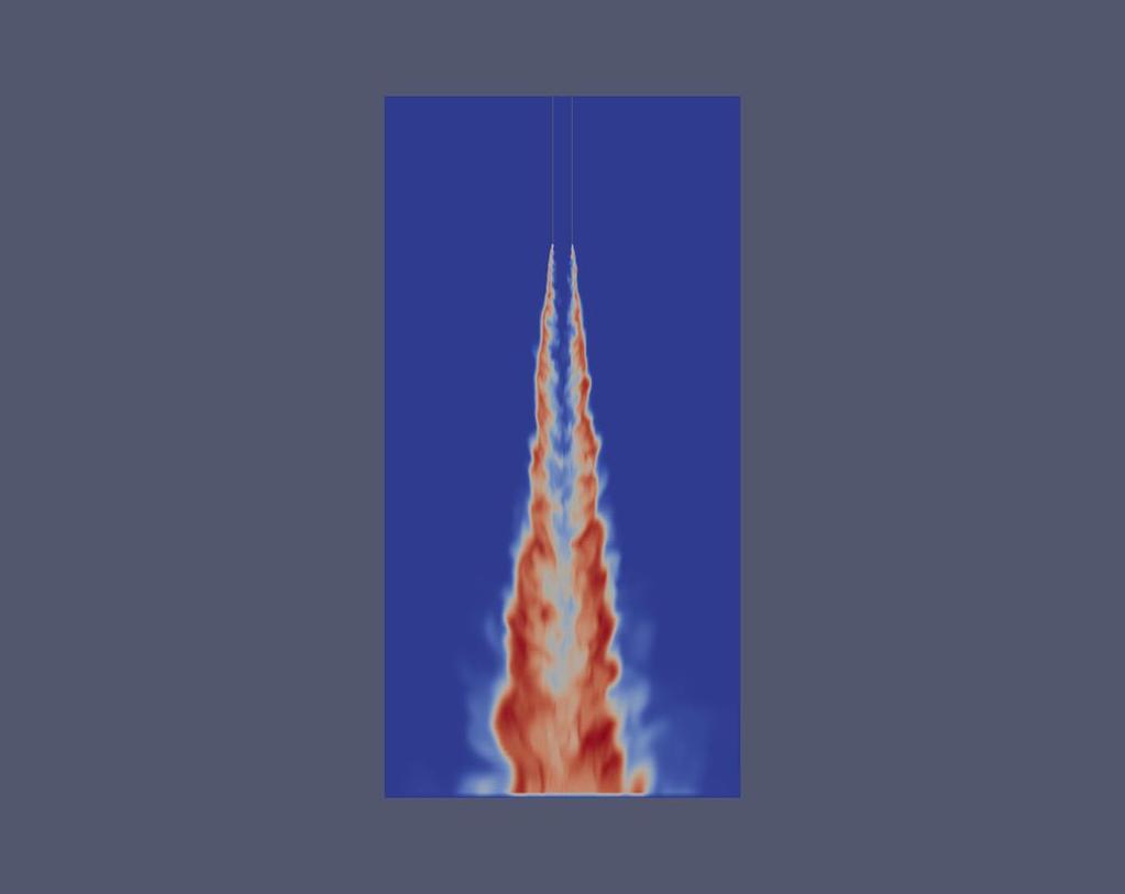
76 69 APPENDIX C: ADDITIONAL LES RESULTS FOR B-1 FLAME Instantaneous and mean contour plots of B-1 flame are listed below for temperature, mixture fraction, and species.
77 7
78 71
LES of the Sandia Flame D Using an FPV Combustion Model
 Available online at www.sciencedirect.com ScienceDirect Energy Procedia 82 (2015 ) 402 409 ATI 2015-70th Conference of the ATI Engineering Association LES of the Sandia Flame D Using an FPV Combustion
IMPROVED POLLUTANT PREDICTIONS IN LARGE-EDDY SIMULATIONS OF TURBULENT NON-PREMIXED COMBUSTION BY CONSIDERING SCALAR DISSIPATION RATE FLUCTUATIONS
 Proceedings of the Combustion Institute, Volume 9, 00/pp. 1971 1978 IMPROVED POLLUTANT PREDICTIONS IN LARGE-EDDY SIMULATIONS OF TURBULENT NON-PREMIXED COMBUSTION BY CONSIDERING SCALAR DISSIPATION RATE
A comparison between two different Flamelet reduced order manifolds for non-premixed turbulent flames
 8 th U. S. National Combustion Meeting Organized by the Western States Section of the Combustion Institute and hosted by the University of Utah May 19-22, 2013 A comparison between two different Flamelet
Large-eddy simulation of an industrial furnace with a cross-flow-jet combustion system
 Center for Turbulence Research Annual Research Briefs 2007 231 Large-eddy simulation of an industrial furnace with a cross-flow-jet combustion system By L. Wang AND H. Pitsch 1. Motivation and objectives
Large-Eddy Simulation of Turbulent Combustion
 Annu. Rev. Fluid Mech. 2006. 38:453 82 The Annual Review of Fluid Mechanics is online at fluid.annualreviews.org doi: 10.1146/annurev.fluid. 38.050304.092133 Copyright c 2006 by Annual Reviews. All rights
An Unsteady/Flamelet Progress Variable Method for LES of Nonpremixed Turbulent Combustion
 43rd AIAA Aerospace Sciences Meeting and Exhibit, -3 Jan 25, Reno, NV An Unsteady/Flamelet Progress Variable Method for LES of Nonpremixed Turbulent Combustion Heinz Pitsch and Matthias Ihme Stanford University,
The influence of C ϕ is examined by performing calculations with the values C ϕ =1.2, 1.5, 2.0 and 3.0 for different chemistry mechanisms.
 The Influence of Chemical Mechanisms on PDF Calculations of Nonpremixed Piloted Jet Flames Renfeng Cao and Stephen B. Pope Sibley School of Mechanical and Aerospace Engineering, Cornell University, Ithaca,
Steady Laminar Flamelet Modeling for turbulent non-premixed Combustion in LES and RANS Simulations
 Sonderforschungsbereich/Transregio 4 Annual Report 213 139 Steady Laminar Flamelet Modeling for turbulent non-premixed Combustion in LES and RANS Simulations By H. Müller, C. A. Niedermeier, M. Pfitzner
Lecture 10 Turbulent Combustion: The State of the Art
 Lecture 10 Turbulent Combustion: The State of the Art 10.-1 Engineering applications are typically turbulent turbulence models These models use systematic mathematical derivations based on the Navier-
Capturing localised extinction in Sandia Flame F with LES-CMC
 Loughborough University Institutional Repository Capturing localised extinction in Sandia Flame F with - This item was submitted to Loughborough University's Institutional Repository by the/an author.
ANSYS Advanced Solutions for Gas Turbine Combustion. Gilles Eggenspieler 2011 ANSYS, Inc.
 ANSYS Advanced Solutions for Gas Turbine Combustion Gilles Eggenspieler ANSYS, Inc. 1 Agenda Steady State: New and Existing Capabilities Reduced Order Combustion Models Finite-Rate Chemistry Models Chemistry
Advanced Turbulence Models for Emission Modeling in Gas Combustion
 1 Advanced Turbulence Models for Emission Modeling in Gas Combustion Ville Tossavainen, Satu Palonen & Antti Oksanen Tampere University of Technology Funding: Tekes, Metso Power Oy, Andritz Oy, Vattenfall
RESOLVING TURBULENCE- CHEMISTRY INTERACTIONS IN MIXING-CONTROLLED COMBUSTION WITH LES AND DETAILED CHEMISTRY
 RESOLVING TURBULENCE- CHEMISTRY INTERACTIONS IN MIXING-CONTROLLED COMBUSTION WITH LES AND DETAILED CHEMISTRY Convergent Science White Paper COPYRIGHT 218 CONVERGENT SCIENCE. All rights reserved. OVERVIEW
Best Practice Guidelines for Combustion Modeling. Raphael David A. Bacchi, ESSS
 Best Practice Guidelines for Combustion Modeling Raphael David A. Bacchi, ESSS PRESENTATION TOPICS Introduction; Combustion Phenomenology; Combustion Modeling; Reaction Mechanism; Radiation; Case Studies;
PDF Modeling and Simulation of Premixed Turbulent Combustion
 Monte Carlo Methods Appl. Vol. No. (), pp. 43 DOI 5 / MCMA.7. c de Gruyter PDF Modeling and Simulation of Premixed Turbulent Combustion Michael Stöllinger and Stefan Heinz Abstract. The use of probability
Numerical Investigation of Ignition Delay in Methane-Air Mixtures using Conditional Moment Closure
 21 st ICDERS July 23-27, 27 Poitiers, France Numerical Investigation of Ignition Delay in Methane-Air Mixtures using Conditional Moment Closure Ahmad S. El Sayed, Cécile B. Devaud Department of Mechanical
Lecture 9 Laminar Diffusion Flame Configurations
 Lecture 9 Laminar Diffusion Flame Configurations 9.-1 Different Flame Geometries and Single Droplet Burning Solutions for the velocities and the mixture fraction fields for some typical laminar flame configurations.
PDF modeling and simulation of premixed turbulent combustion
 Monte Carlo Methods Appl. Vol. 4 No. 4 (8), pp. 343 377 DOI. / MCMA.8.6 c de Gruyter 8 PDF modeling and simulation of premixed turbulent combustion Michael Stöllinger and Stefan Heinz Abstract. The use
Sensitivity analysis of LES-CMC predictions of piloted jet flames
 Loughborough University Institutional Repository Sensitivity analysis of LES-CMC predictions of piloted jet flames This item was submitted to Loughborough University's Institutional Repository by the/an
Simulation of Turbulent Lifted Flames and their Transient Propagation
 25 th ICDERS August 2-7th, 2015 Leeds, UK Simulation of Turbulent Lifted Flames and their Transient Propagation S. Ruan, Z. Chen, N. Swaminathan University of Cambridge Cambridge, UK 1 Introduction Turbulent
Large-eddy simulation of a bluff-body-stabilized non-premixed flame using a recursive filter-refinement procedure
 Combustion and Flame 142 (2005) 329 347 www.elsevier.com/locate/combustflame Large-eddy simulation of a bluff-body-stabilized non-premixed flame using a recursive filter-refinement procedure Venkatramanan
DNS and LES of Turbulent Combustion
 Computational Fluid Dynamics In Chemical Reaction Engineering IV June 19-24, 2005 Barga, Italy DNS and LES of Turbulent Combustion Luc Vervisch INSA de Rouen, IUF, CORIA-CNRS Pascale Domingo, Julien Réveillon
Subgrid-scale mixing of mixture fraction, temperature, and species mass fractions in turbulent partially premixed flames
 Available online at www.sciencedirect.com Proceedings of the Combustion Institute 34 (2013) 1231 1239 Proceedings of the Combustion Institute www.elsevier.com/locate/proci Subgrid-scale mixing of mixture
LES of an auto-igniting C 2 H 4 flame DNS
 Center for Turbulence Research Annual Research Briefs 2011 237 LES of an auto-igniting C 2 H 4 flame DNS By E. Knudsen, E. S. Richardson, J. H. Chen AND H. Pitsch 1. Motivation and objectives Large eddy
ADVANCED DES SIMULATIONS OF OXY-GAS BURNER LOCATED INTO MODEL OF REAL MELTING CHAMBER
 ADVANCED DES SIMULATIONS OF OXY-GAS BURNER LOCATED INTO MODEL OF REAL MELTING CHAMBER Ing. Vojtech Betak Ph.D. Aerospace Research and Test Establishment Department of Engines Prague, Czech Republic Abstract
Overview of Turbulent Reacting Flows
 Overview of Turbulent Reacting Flows Outline Various Applications Overview of available reacting flow models LES Latest additions Example Cases Summary Reacting Flows Applications in STAR-CCM+ Ever-Expanding
LES Approaches to Combustion
 LES Approaches to combustion LES Approaches to combustion LES Approaches to Combustion W P Jones Department of Mechanical Engineering Imperial College London Exhibition Road London SW7 2AZ SIG on Combustion
The development of advanced combustion systems is mainly controlled by the objective to increase fuel
 47th AIAA Aerospace Sciences Meeting Including The New Horizons Forum and Aerospace Exposition 5-8 January 29, Orlando, Florida AIAA 29-239 Large-Eddy Simulation of a Turbulent Lifted Flame in a Vitiated
EVALUATION OF FOUR TURBULENCE MODELS IN THE INTERACTION OF MULTI BURNERS SWIRLING FLOWS
 EVALUATION OF FOUR TURBULENCE MODELS IN THE INTERACTION OF MULTI BURNERS SWIRLING FLOWS A Aroussi, S Kucukgokoglan, S.J.Pickering, M.Menacer School of Mechanical, Materials, Manufacturing Engineering and
Towards regime identification and appropriate chemistry tabulation for computation of autoigniting turbulent reacting flows
 Center for Turbulence Research Annual Research Briefs 009 199 Towards regime identification and appropriate chemistry tabulation for computation of autoigniting turbulent reacting flows By M. Kostka, E.
LARGE-EDDY SIMULATION OF PARTIALLY PREMIXED TURBULENT COMBUSTION
 LARGE-EDDY SIMULATION OF PARTIALLY PREMIXED TURBULENT COMBUSTION Heinz Pitsch Mechanical Engineering Department Stanford University Stanford, CA 94305, USA h.pitsch@stanford.edu ABSTRACT The development
Consistent turbulence modeling in a hybrid LES/RANS PDF method for non-premixed flames
 Consistent turbulence modeling in a hybrid LES/RANS PDF method for non-premixed flames F. Ferraro, Y. Ge and M. Pfitzner Institut für Thermodynamik, Fakultät für Luft- und Raumfahrrttechnik Universität
Numerical simulation of oxy-fuel jet flames using unstructured LES-CMC
 Loughborough University Institutional Repository Numerical simulation of oxy-fuel jet flames using unstructured LES-CMC This item was submitted to Loughborough University's Institutional Repository by
Introduction Flares: safe burning of waste hydrocarbons Oilfields, refinery, LNG Pollutants: NO x, CO 2, CO, unburned hydrocarbons, greenhouse gases G
 School of Process, Environmental and Materials Engineering Computational study of combustion in flares: structure and emission of a jet flame in turbulent cross-flow GERG Academic Network Event Brussels
hydrogen auto ignition in a turbulent co flow of heated air with LES and CMC approach.
 biblio.ugent.be The UGent Institutional Repository is the electronic archiving and dissemination platform for all UGent research publications. Ghent University has implemented a mandate stipulating that
MUSCLES. Presented by: Frank Wetze University of Karlsruhe (TH) - EBI / VB month review, 21 September 2004, Karlsruhe
 - EBI / VB month review, 21 September 2004, Karlsruhe") MUSCLES Modelling of UnSteady Combustion in Low Emission Systems G4RD-CT-2002-00644 R&T project within the 5 th Framework program of the European Union: 1 Numerical computations of reacting flow field
MUSCLES Modelling of UnSteady Combustion in Low Emission Systems G4RD-CT-2002-00644 R&T project within the 5 th Framework program of the European Union: 1 Numerical computations of reacting flow field
Soot formation in turbulent non premixed flames
 Soot formation in turbulent non premixed flames A. Cuoci 1, A. Frassoldati 1, D. Patriarca 1, T. Faravelli 1, E. Ranzi 1, H. Bockhorn 2 1 Dipartimento di Chimica, Materiali e Ing. Chimica, Politecnico
DEVELOPMENT OF CFD MODEL FOR A SWIRL STABILIZED SPRAY COMBUSTOR
 DRAFT Proceedings of ASME IMECE: International Mechanical Engineering Conference & Exposition Chicago, Illinois Nov. 5-10, 2006 IMECE2006-14867 DEVELOPMENT OF CFD MODEL FOR A SWIRL STABILIZED SPRAY COMBUSTOR
A G-equation formulation for large-eddy simulation of premixed turbulent combustion
 Center for Turbulence Research Annual Research Briefs 2002 3 A G-equation formulation for large-eddy simulation of premixed turbulent combustion By H. Pitsch 1. Motivation and objectives Premixed turbulent
This article appeared in a journal published by Elsevier. The attached copy is furnished to the author for internal non-commercial research and
 This article appeared in a journal published by Elsevier. The attached copy is furnished to the author for internal non-commercial research and education use, including for instruction at the authors institution
DARS overview, IISc Bangalore 18/03/2014
 www.cd-adapco.com CH2O Temperatur e Air C2H4 Air DARS overview, IISc Bangalore 18/03/2014 Outline Introduction Modeling reactions in CFD CFD to DARS Introduction to DARS DARS capabilities and applications
Thermal NO Predictions in Glass Furnaces: A Subgrid Scale Validation Study
 Feb 12 th 2004 Thermal NO Predictions in Glass Furnaces: A Subgrid Scale Validation Study Padmabhushana R. Desam & Prof. Philip J. Smith CRSIM, University of Utah Salt lake city, UT-84112 18 th Annual
Investigation of the scalar variance and scalar dissipation rate in URANS and LES
 Investigation of the scalar variance and scalar dissipation rate in URANS and LES by Isaac Keeheon Ye A thesis presented to the University of Waterloo in fulfillment of the thesis requirement for the degree
Process Chemistry Toolbox - Mixing
 Process Chemistry Toolbox - Mixing Industrial diffusion flames are turbulent Laminar Turbulent 3 T s of combustion Time Temperature Turbulence Visualization of Laminar and Turbulent flow http://www.youtube.com/watch?v=kqqtob30jws
Lecture 14. Turbulent Combustion. We know what a turbulent flow is, when we see it! it is characterized by disorder, vorticity and mixing.
 Lecture 14 Turbulent Combustion 1 We know what a turbulent flow is, when we see it! it is characterized by disorder, vorticity and mixing. In a fluid flow, turbulence is characterized by fluctuations of
LOW TEMPERATURE MODEL FOR PREMIXED METHANE FLAME COMBUSTION
 ISTP-16, 2005, PRAGUE 16TH INTERNATIONAL SYMPOSIUM ON TRANSPORT PHENOMENA LOW TEMPERATURE MODEL FOR PREMIXED METHANE FLAME MBUSTION M. Forman, J.B.W.Kok,M. Jicha Department of Thermodynamics and Environmental
D. VEYNANTE. Introduction à la Combustion Turbulente. Dimanche 30 Mai 2010, 09h00 10h30
 D. VEYNANTE Introduction à la Combustion Turbulente Dimanche 30 Mai 2010, 09h00 10h30 Introduction to turbulent combustion D. Veynante Laboratoire E.M2.C. CNRS - Ecole Centrale Paris Châtenay-Malabry France
LES-PDF SIMULATION OF A HIGHLY SHEARED TURBULENT PILOTED PREMIXED FLAME
 LES-PDF SIMULATION OF A HIGHLY SHEARED TURBULENT PILOTED PREMIXED FLAME Abstract V. N. Prasad, K. H. Luo and W. P. Jones k.h.luo@soton.ac.uk School of Engineering Sciences, University of Southampton, Southampton
Numerical Simulations of Hydrogen Auto-ignition in a Turbulent Co-flow of Heated Air with a Conditional Moment Closure
 Numerical Simulations of Hydrogen Auto-ignition in a Turbulent Co-flow of Heated Air with a Conditional Moment Closure I. Stanković*, 1, A. Triantafyllidis, E. Mastorakos, C. Lacor 3 and B. Merci 1, 4
Published in: Proceedings of the Fluent Benelux User Group Meeting, 6-7 October 2005, Wavre, Belgium
 The application of Flamelet Generated Manifolds in partailly-premixed flames Ramaekers, W.J.S.; Albrecht, B.A.; van Oijen, J.A.; de Goey, L.P.H.; Eggels, R.L.G.M. Published in: Proceedings of the Fluent
Modelling Detailed-Chemistry Effects on Turbulent Diffusion Flames using a Parallel Solution-Adaptive Scheme
 Modelling Detailed-Chemistry Effects on Turbulent Diffusion Flames using a Parallel Solution-Adaptive Scheme by Pradeep Kumar Jha A thesis submitted in conformity with the requirements for the degree of
Direct numerical simulation of a turbulent reacting jet
 Center for Turbulence Research Annual Research Briefs 999 59 Direct numerical simulation of a turbulent reacting jet By B. J. Boersma. Motivation and objectives Turbulent reacting jets are important in
Modeling of Wall Heat Transfer and Flame/Wall Interaction A Flamelet Model with Heat-Loss Effects
 9 th U. S. National Combustion Meeting Organized by the Central States Section of the Combustion Institute May 17-20, 2015 Cincinnati, Ohio Modeling of Wall Heat Transfer and Flame/Wall Interaction A Flamelet
CFD and Kinetic Analysis of Bluff Body Stabilized Flame
 CFD and Kinetic Analysis of Bluff Body Stabilized ame A. Dicorato, E. Covelli, A. Frassoldati, T. Faravelli, E. Ranzi Dipartimento di Chimica, Materiali e Ingegneria Chimica, Politecnico di Milano, ITALY
K. A. Kemenov, H. Wang, S. B. Pope Sibley School of Mechanical and Aerospace Engineering, Cornell University, Ithaca, NY 14853
 Grid resolution effects on LES of a piloted methane-air flame K. A. Kemenov, H. Wang, S. B. Pope Sibley School of Mechanical and Aerospace Engineering, Cornell University, Ithaca, NY 14853 Abstract The
Modeling Turbulent Combustion
 Modeling Turbulent Combustion CEFRC Combustion Summer School 2014 Prof. Dr.-Ing. Heinz Pitsch Copyright 2014 by Heinz Pitsch. This material is not to be sold, reproduced or distributed without prior written
Large-Eddy Simulation of Reacting Turbulent Flows in Complex Geometries
 K. Mahesh Aerospace Engineering and Mechanics, University of Minnesota, 107 Akerman Hall, Minneapolis, MN 55455 G. Constantinescu Civil and Environmental Engineering, University of Iowa, Iowa City, IA
Flamelet modelling of non-premixed turbulent combustion with local extinction and re-ignition
 INSTITUTE OF PHYSICS PUBLISHING Combust. Theory Modelling 7 (2003) 317 332 COMBUSTION THEORY AND MODELLING PII: S1364-7830(03)38343-3 Flamelet modelling of non-premixed turbulent combustion with local
Conditional statistics for passive-scalar mixing in a confined rectangular turbulent jet
 Chemical and Biological Engineering Publications Chemical and Biological Engineering 2007 Conditional statistics for passive-scalar mixing in a confined rectangular turbulent jet H. Feng Iowa State University
A validation study of the flamelet approach s ability to predict flame structure when fluid mechanics are fully resolved
 Center for Turbulence Research Annual Research Briefs 2009 185 A validation study of the flamelet approach s ability to predict flame structure when fluid mechanics are fully resolved By E. Knudsen AND
Conditional-moment Closure with Differential Diffusion for Soot Evolution in Fire
 Chemical and Biological Engineering Conference Presentations and Proceedings Chemical and Biological Engineering 26 Conditional-moment Closure with Differential Diffusion for Soot Evolution in Fire J.
Large Eddy Simulation of Piloted Turbulent Premixed Flame
 Large Eddy Simulation of Piloted Turbulent Premixed Flame Veeraraghava Raju Hasti, Robert P Lucht and Jay P Gore Maurice J. Zucrow Laboratories School of Mechanical Engineering Purdue University West Lafayette,
Combustion Theory and Applications in CFD
 Combustion Theory and Applications in CFD Princeton Combustion Summer School 2018 Prof. Dr.-Ing. Heinz Pitsch Copyright 201 8 by Heinz Pitsch. This material is not to be sold, reproduced or distributed
Flow Structure Investigations in a "Tornado" Combustor
 Flow Structure Investigations in a "Tornado" Combustor Igor Matveev Applied Plasma Technologies, Falls Church, Virginia, 46 Serhiy Serbin National University of Shipbuilding, Mikolayiv, Ukraine, 545 Thomas
NUMERICAL ANALYSIS OF TURBULENT FLAME IN AN ENCLOSED CHAMBER
 NUMERICAL ANALYSIS OF TURBULENT FLAME IN AN ENCLOSED CHAMBER Naveen Kumar D 1*, Pradeep R 2 and Bhaktavatsala H R 3 1 Assistant Professor Department of Mechanical Engineering, M S Engineering College,
A Priori Testing of Flamelet Generated Manifolds for Turbulent Partially Premixed Methane/Air Flames
 DOI 10.1007/s10494-009-9223-1 A Priori Testing of Flamelet Generated Manifolds for Turbulent Partially Premixed Methane/Air Flames W. J. S. Ramaekers J. A. van Oijen L. P. H. de Goey Received: 7 September
On the transient modelling of impinging jets heat transfer. A practical approach
 Turbulence, Heat and Mass Transfer 7 2012 Begell House, Inc. On the transient modelling of impinging jets heat transfer. A practical approach M. Bovo 1,2 and L. Davidson 1 1 Dept. of Applied Mechanics,
Insights into Model Assumptions and Road to Model Validation for Turbulent Combustion
 Insights into Model Assumptions and Road to Model Validation for Turbulent Combustion Venke Sankaran AFRL/RQR 2015 AFRL/RQR Basic Research Review UCLA Jan 20, 2015 AFTC PA Release# 15011, 16 Jan 2015 Goals
Assessment of a flame surface density-based subgrid turbulent combustion model for nonpremixed flames of wood pyrolysis gas
 PHYSICS OF FLUIDS VOLUME 16, NUMBER 10 OCTOBER 2004 Assessment of a flame surface density-based subgrid turbulent combustion model for nonpremixed flames of wood pyrolysis gas Xiangyang Zhou a) Department
Mixing Models for Large-Eddy Simulation of Nonpremixed Turbulent Combustion
 S. M. debruynkops Lecturer J. J. Riley Professor Department of Mechanical Engineering, University of Washington, Box 35600, Seattle, WA 98195-600 Mixing Models for Large-Eddy Simulation of Nonpremixed
Impact of numerical method on auto-ignition in a temporally evolving mixing layer at various initial conditions
 Journal of Physics: Conference Series PAPER OPEN ACCESS Impact of numerical method on auto-ignition in a temporally evolving mixing layer at various initial conditions To cite this article: A Rosiak and
TOPICAL PROBLEMS OF FLUID MECHANICS 97
 TOPICAL PROBLEMS OF FLUID MECHANICS 97 DOI: http://dx.doi.org/10.14311/tpfm.2016.014 DESIGN OF COMBUSTION CHAMBER FOR FLAME FRONT VISUALISATION AND FIRST NUMERICAL SIMULATION J. Kouba, J. Novotný, J. Nožička
NO x Emissions Prediction from a Turbulent Diffusion Flame
 NO x Emissions Prediction from a Turbulent Diffusion Flame Akpan, Patrick 1 and Njiofor, Tobenna 2 1 Department of Mechanical Engineering, University of Nigeria, Nsukka 2 Process Systems Engineering, Cranfield
Evaluation of a Scalar Probability Density Function Approach for Turbulent Jet Nonpremixed Flames
 THE 5 TH ASIAN COMPUTAITIONAL FLUID DYNAMICS BUSAN, KOREA, OCTOBER 7 30, 003 Evaluation of a Scalar Probability Density Function Approach for Turbulent Jet Nonpremixed Flames S. Noda, Y. Horitani and K.
LES-CMC of a dilute acetone spray flame with pre-vapor using two conditional moments
 LES-CMC of a dilute acetone spray flame with pre-vapor using two conditional moments S. Ukai, A. Kronenburg, O.T. Stein Institut für Technische Verbrennung, Universität Stuttgart, 774 Stuttgart, Germany
M U S C L E S. Modelling of UnSteady Combustion in Low Emission Systems. Project No. GRD Contract No. G4RD-CT
 M U S C L E S Modelling of UnSteady Combustion in Low Emission Systems Project No. GRD-200-4098 Work Package 2 Prediction of unsteady reacting flow and validation Task 2. Prediction of lean blow out in
Investigation of ignition dynamics in a H2/air mixing layer with an embedded vortex
 Paper # 070LT-0211 The 8th US National Meeting of the Combustion Institute, Park City, UT, May 19-22, 2013 Investigation of ignition dynamics in a H2/air mixing layer with an embedded vortex S.K. Menon
Budget analysis and model-assessment of the flamelet-formulation: Application to a reacting jet-in-cross-flow
 Center for Turbulence Research Proceedings of the Summer Program 212 397 Budget analysis and model-assessment of the flamelet-formulation: Application to a reacting jet-in-cross-flow By W. L. Chan, Y.
Modeling extinction and reignition in turbulent nonpremixed combustion using a doubly-conditional moment closure approach
 PHYSICS OF FLUIDS VOLUME 13, NUMBER 12 DECEMBER 2001 Modeling extinction and reignition in turbulent nonpremixed combustion using a doubly-conditional moment closure approach Chong M. Cha a) Center for
Numerical Methods in Aerodynamics. Turbulence Modeling. Lecture 5: Turbulence modeling
 Turbulence Modeling Niels N. Sørensen Professor MSO, Ph.D. Department of Civil Engineering, Alborg University & Wind Energy Department, Risø National Laboratory Technical University of Denmark 1 Outline
Examination of the effect of differential molecular diffusion in DNS of turbulent non-premixed flames
 Examination of the effect of differential molecular diffusion in DNS of turbulent non-premixed flames Chao Han a, David O. Lignell b, Evatt R. Hawkes c, Jacqueline H. Chen d, Haifeng Wang a, a School of
An Introduction to Theories of Turbulence. James Glimm Stony Brook University
 An Introduction to Theories of Turbulence James Glimm Stony Brook University Topics not included (recent papers/theses, open for discussion during this visit) 1. Turbulent combustion 2. Turbulent mixing
S. T. Smith Iowa State University. Rodney O. Fox Iowa State University,
 Chemical and Biological Engineering Publications Chemical and Biological Engineering 2007 A term-by-term direct numerical simulation validation study of the multi-environment conditional probability-density-function
A NUMERICAL ANALYSIS OF COMBUSTION PROCESS IN AN AXISYMMETRIC COMBUSTION CHAMBER
 SCIENTIFIC RESEARCH AND EDUCATION IN THE AIR FORCE-AFASES 2016 A NUMERICAL ANALYSIS OF COMBUSTION PROCESS IN AN AXISYMMETRIC COMBUSTION CHAMBER Alexandru DUMITRACHE*, Florin FRUNZULICA ** *Institute of
An evaluation of a conservative fourth order DNS code in turbulent channel flow
 Center for Turbulence Research Annual Research Briefs 2 2 An evaluation of a conservative fourth order DNS code in turbulent channel flow By Jessica Gullbrand. Motivation and objectives Direct numerical
Flow and added small-scale topologies in a turbulent premixed flame
 Flow and added small-scale topologies in a turbulent premixed flame L. Cifuentes*, A. Kempf* and C. Dopazo** luis.cifuentes@uni-due.de *University of Duisburg-Essen, Chair of Fluid Dynamics, Duisburg -
Introduction to Turbulence and Turbulence Modeling
 Introduction to Turbulence and Turbulence Modeling Part I Venkat Raman The University of Texas at Austin Lecture notes based on the book Turbulent Flows by S. B. Pope Turbulent Flows Turbulent flows Commonly
Lecture 8 Laminar Diffusion Flames: Diffusion Flamelet Theory
 Lecture 8 Laminar Diffusion Flames: Diffusion Flamelet Theory 8.-1 Systems, where fuel and oxidizer enter separately into the combustion chamber. Mixing takes place by convection and diffusion. Only where
Eulerian models. 2.1 Basic equations
 2 Eulerian models In this chapter we give a short overview of the Eulerian techniques for modelling turbulent flows, transport and chemical reactions. We first present the basic Eulerian equations describing
Assessment of turbulence-chemistry interaction models in the computation of turbulent nonpremixed
 Journal of Physics: Conference Series PAPER OPEN ACCESS Assessment of turbulence-chemistry interaction models in the computation of turbulent nonpremixed flames To cite this article: M T Lewandowski and
Evaluation of Liquid Fuel Spray Models for Hybrid RANS/LES and DLES Prediction of Turbulent Reactive Flows
 Evaluation of Liquid Fuel Spray Models for Hybrid RANS/LES and DLES Prediction of Turbulent Reactive Flows by Ali Afshar A thesis submitted in conformity with the requirements for the degree of Masters
Turbulent Boundary Layers & Turbulence Models. Lecture 09
 Turbulent Boundary Layers & Turbulence Models Lecture 09 The turbulent boundary layer In turbulent flow, the boundary layer is defined as the thin region on the surface of a body in which viscous effects
Conditional Moment Closure With a Progress Variable Approach
 Conditional Moment Closure With a Progress Variable Approach Harry Lehtiniemi* 1, Anders Borg 1, and Fabian Mauss 2 1 Lund Combustion Engineering LOGE AB, Scheelevägen 17, SE-22370 Lund,
UQ in Reacting Flows
 UQ in Reacting Flows Planetary Entry Simulations High-Temperature Reactive Flow During descent in the atmosphere vehicles experience extreme heating loads The design of the thermal protection system (TPS)
Turbulence Resolution Scale Dependence in Large-Eddy Simulations of a Jet Flame
 DOI 10.1007/s10494-011-9380-x Turbulence Resolution Scale Dependence in Large-Eddy Simulations of a Jet Flame Konstantin A. Kemenov Haifeng Wang Stephen B. Pope Received: 20 April 2011 / Accepted: 8 November
NUMERICAL SIMULATION OF LDI COMBUSTOR WITH DISCRETE-JET SWIRLERS USING RE-STRESS MODEL IN THE KIVA CODE
 NUMERICAL SIMULATION OF LDI COMBUSTOR WITH DISCRETE-JET SWIRLERS USING RE-STRESS MODEL IN THE KIVA CODE S. L. Yang, C. Y. Teo, and Y. K. Siow Department of Mechanical Engineering Engineering Mechanics
Numerical Investigations of a Hydrogen Jet Flame in a Vitiated
 Numerical Investigations of a Hydrogen Jet Flame in a Vitiated Coflow by Donald Jerome Frederick A dissertation submitted in partial satisfaction of the requirements for the degree of Doctor of Philosophy
S. Kadowaki, S.H. Kim AND H. Pitsch. 1. Motivation and objectives
 Center for Turbulence Research Annual Research Briefs 2005 325 The dynamics of premixed flames propagating in non-uniform velocity fields: Assessment of the significance of intrinsic instabilities in turbulent
Numerical Simulation of Hydrogen Gas Turbines using Flamelet Generated Manifolds technique on Open FOAM
 Numerical Simulation of Hydrogen Gas Turbines using Flamelet Generated Manifolds technique on Open FOAM Alessio Fancello (M.Sc.) Department of Mechanical Engineering Combustion Technology Technische Universiteit
Development of One-Step Chemistry Models for Flame and Ignition Simulation
 Development of One-Step Chemistry Models for Flame and Ignition Simulation S.P.M. Bane, J.L. Ziegler, and J.E. Shepherd Graduate Aerospace Laboratories California Institute of Technology Pasadena, CA 91125