By A. Lemanski 1. Alberti I. Mack. January 1968 THE BOEING COMPANY VERTOL DIVISION PHILADELPHIA, PENNSYLVANIA
|
|
|
- Marcia Knight
- 5 years ago
- Views:
Transcription
1 - J. u USAAVLABS TECHNICAL REPORT AK EVALUATION OF CONFORMAL CONTACT GEARS By A. Lemanski 1. Alberti I. Mack January 1968 U. S. ARMY AVIATION MATERIEL LABORATORIES FORT EUSTIS, VIRGINIA CONTRACT DA AMC-389(T) This document has been approved for public release and sale; its distribution is unlimited. THE BOEING COMPANY VERTOL DIVISION PHILADELPHIA, PENNSYLVANIA Reproduced by the CLEARINGHOUSE for Federal Scientific & Technical Information Springfield Va rt- V' ' V w 7/

2 Disclaimers The findings in this report are not to be construed as an official Department of the Army position unless so designated by other authorized documents. When Government drawings, specifications, or other data are used for any purpose other than in connection with a definitely related Government procurement operation, the United States Government thereby incurs no responsibility nor any obligation whatseover; and the fact that the Government may have formulated, furnished, or in any way supplied the said drawings, specifications, or other data is not to be regarded by impli cation or otherwise as in any manner licensing the holder or any other person or corporation, or conveying any rights or permission, to manufacture, use, or sell any patented invention that may in any way be related thereto. Trade names cited in this report do not constitute an official endorsement or approval of the use of such commercial hardware or software. Disposition Instructions Destroy this report when no longer needed. originator. Do not return it to w u i A i.- V,:nU ",^M DUl.


3 AN EVALUATION OF CONFORMAL CONTACT GEARS A. J. Lemanski, et al Boeing Company Philadelphia, Pennsylvania January 1968 AD
.")
4 I DEPARTMENT OF THE ARMY U.. ANMV AVIATION MATtMB. LABONATOMC* FOKtT KUSTI*. VMOiMA am04 ; h This report represent««part of a research program established to Investigate advanced gear design criteria. The main efforts of the program are directed toward dynamic load tests of specimen conformal contact gearing (Wlldhaber-Novikov gear tooth form). The Command concurs In the conclusions reported herein. The results obtained from this specific study Indicate that extensive research Investigations must be conducted before a complete evaluation of conformal contact gearing for aircraft application can be made.
 USAAVLABS Technical Report")

5 . Wi!««vWM»www--i- n ",.-. ir ^ 'W» mntm'linax-ttxv*tf*:-: ' ' * Task 1M125901A01410 Contract DA AMC-389(T) USAAVLABS Technical Report January 1968 AN EVALUATION OF C0NF0RMA1. CONTACT GEARS Final Report D8-0854A By A. Lemanski J. Alberti J. Mack Prepared by The Boeing Company Vertol Division for U 1. ARMY AVIATION MATERIEL LABORATORIES FORT EUSTIS, VIRGINIA This document has been approved for public release and sale; its distribution is unlimited. T? ; - *'i*&m'imim&is^r*^»im\im*aiimimmm imi

6 SUMMARY This report concludes the program for the evaluation of one form of the conformal gear geometry conducted by The Boeing Company, Vertol Division, under Contract DA AMC-389(T), initiated on 22 April The program comprised the design, fabrication, inspection and load testing of one form of the conformal gear tooth geometry. The test gears were case carburized and ground in accordance with high aircraft quality standards and the applicable Vertol Division specifications. Load capacity of this particular tooth form was determined by a programmed increase in load until failure was attained. Results of this test program indicated that the gear merber was the weakest in bending strength and that a better balance between contact stress and bending stress will be necessary in future designs. The tooth strain survey indicated that the trends of the strain readings at the gages, as the load zone passed across the face width, were similar to the results shown in USAAVLABS Technical Report iii

7 HHH WWMwwi i u MWHÜ FOREWORD Acknowledgement is made to the following organizations for their assistance and contributions in the fabrication and inspection of the conformal gears during this program: Fellows Gear Shaper Company, Springfield, Vermont National Broach and Machine Company, Detroit, Michigan Bendix Corporation, Industrial Metrology Division, Ann Arbor, Michigan Michigan Tool Division, Excello Corporation, Detroit, Michigan Acknowledgement is also made to Professors William Murphy and Paul Nenz of the Villanova University Mechanical Engineering Department for their assistance and contributions during the test program. Acknowledgement is also made to Mr. Robert Spencer of the Acoustics Unit of The Boeing Company, Vertol Division, for conducting the noise level test program.


8 TABLE OF CONTENTS lass. SUMMARY ill FOREWORD v LIST OF ILLUSTRATIONS viii LIST OF TABLES X INTRODUCTION 1 DESCRIPTION OF TEST ITEM 2 METHODS OF INSPECTION 12 STRAIN SURVEY 18 LOAD TESTS 28 DISCUSSION OF TEST RESULTS 47 CONCLUSIONS 53 APPENDIX Noise Level Tests - Conformal Gears 55 DISTRIBUTION 60 Vll
 3,5 2 Comparison of Geometry of SK16207 Test Gears With SK13264 Test Gears 9 3 Offset Pinion Fixture for")
9 . w*wi^-'^^mi»w'(*./»'^k», *'-'''"f', *.ra*'^w'mr-^i«--> -. «, - f%i LIST OF ILLUSTRATIONS Figure Page 1 Conformal Gear Drawing - SK16207 (2 sheets) 3,5 2 Comparison of Geometry of SK16207 Test Gears With SK13264 Test Gears 9 3 Offset Pinion Fixture for Involute Measuring Instrument 13 4 Pinion Offset Fixture - Principle of Operation 15 5 Coordinate Tracer Schematic 17 6 Strain Gage Locations - Pinion 19 7 Strain Gage Installation - Pinion 20 8 Oscillograph Record of Strain Gage Data Load Overlapping Effect Maximum Strain at 21,800 Inch-Pounds Torque Maximum Strain at 32,550 Inch-Pounds Torque Gear Research Test Stand Test Stand Torquemeter Installation Deadweight Torsion Test Machine Installation of Conformal Gears - Static Pattern Checks Static Gear Patterns - Gear Set No Gear Patterns After Running - Gear Set No Static Gear Patterns - Gear Set No viii
 - Set No. 2... 44 26 Fractured Tooth of Conformal Gear - Set No. 2. 44 27 Fractured Face of Conformal Gear - Set No.")
10 tf^lrmfiwn * Figure Page 19 Gear Patterns After Running - Gear Set No Test Pinions After Final Load Run Conformal Gear (SK ) - Set No Fractured Tooth of Conformal Gear - Set No Fractured Face of Gear Set No Closeup View of Fractured Tooth Conformal Gear (SK ) - Set No Fractured Tooth of Conformal Gear - Set No Fractured Face of Conformal Gear - Set No Origin Area with Arrow Denoting Fatigue Area Case Microstructure of Set No. 1 (Origin Area) Core Microstructure of Set No. 1 (Origin Area) Case Microstructure of Set No. 2 (Origin Area) Graphical Analysis of Gear Sets Nos. 1 and 2 for Effective Case Depth Evaluation Origin Location of Failed Tooth Gear Member - Set No Involute Contact Stress Levels at Pitch Line Vs. Torque Involute Bending Stress Levels Vs. Pinion Torque Schematic of Gear Test Stand Showing Installation of Acoustical Enclosure 57 ix

11 I**"- -IV- Figure Page 37 Wave Analysis - Conformal and Spur Gear LIST OF TABLES Page I Design Specifications 2 II Gear Tooth Inspection Results 11 III Inspection Equipment for Dimensional Control. 12 IV Strain Gage Survey Data (SK , Pinion; SK , Gear) 24 V Load Test Program 34 VI Narrow Band Analysis 57 VII One-Third Octave Band Analysis 57

12 INTRODUCTION The conformal (circular arc profile) gear has been investigated as a means for improving helicopter «peed reduction drives. By overcoming certain inherent limitations of the involute tooth form, the developed conformal tooth form has shown promise of improving current power-to-weight ratios. Both theoretical analysis and experimental evidence published to date indicate that convex profiles of mating involute teeth have less surface in contact than conformal (convex and concave circular arc) profiles. In addition, involute profiles are characterized by variable sliding conditions as contrasted by constant sliding of conformal teeth. As a result, for any given lubricant, the convex involute profiles develop a thinner oil film and generate more heat within the film than corresponding conformal profiles. Therefore, it follows that conformal teeth are inherently more efficient than involute teeth. For the same size and existing material, it should be possible to carry greater loads or to reduce the gear size, for the same load and material. Under sponsorship of USAAVLABS, The Boeing Company, Vertol Division, has conducted theoretical and experimental programs on carburized and ground conformal gears. The initial program resulted in the first published work (USAAVLABS Technical Report 66-8)* covering aircraft quality gears. This first report presented the results of one tooth form of the conformal gear geometry. Problem areas were defined and specific recommendations were made for future design and development work. It was determined that in order to develop the full potential of the conformal gear and to improve further on the highly developed aircraft involute gear, a systematic approach of testing, analyzing, and modifying will be required. In addition, appropriate inspection fixtures and equipment must be designed and fabricated to permit the required dimensional control commensurate with aircraft involute gears. In this direction, the current (second) program was conducted in an effort to explore the recommendations and problem areas presented at the conclusion of the previous program. *Nack, J.C., Alberti, J.P., Lemanski, A.J., AN EXPERIMENTAL EVALUATION OF THE CONFORMAL GEAR, Vertol Division of Boeing, USAAVLABS Technical Report 66-8, U.S. Army Aviation Materiel Laboratories, Fort Eustis, Virginia, January 1966, DA AMC-101(T), Modification 1. (AD )
 evaluation.")
13 DESCRIPTION OF TEST ITEM DESIGN Six test gears utilized in this test program were fabricated by the National Broach and Machine Company, Detroit, Michigan. Two of these test gears were manufactured specifically for a destructive metallurgical (IP-1) evaluation. The SK16207 Conformal Test Gears were manufactured to the following design specifications (Table I). For the complete dimensional data see Figure 1. TABLE I. DESIGN SPECIFICATIONS Pinion Gear Pressure angle, degrees )iametral pitch, inches Number of teeth Pitch diameter, inches Pace width, inches P/D ratio Helix angle, degrees 25 13«25 13' Axial overlap The design specifications selected for the test gears reflect the assumptions and recommendations suggested by USAAVLABS Technical Report Both gear sets are identical except that the pinion in set number 2 (SK ) was crowned, in the lead direction, at the entrance and exit ends. Crown tolerance at both ends was to inch for a nominal distance of 0.50 inch (Figure 1). This modification was accomplished to alleviate possible entrance distress or exit distress caused by deflection of the teeth as they pass through contact.
 Q AOOOATIK [ coownmg of nop - 7 ONLY DlgiMM 8418 '~ O.DIA FWO CMO UPTtS 1 CKOWM BOTH TOOTH fucts AS jlllmtl ON Lf*D 0MI6MM i.")

14 I MIS ««MMOä ItlTN -llm M* I» MCMD MOT IMMITitC (WO»Mt t MUi y-1 MMMITllt iooo MK 3 toll U>T - TWO locktloms MH&NcniC toeo UMTS PARTICU IMiPECTior«MooiMMlNn KK vcfttol SPEC MS iu a IOMTIFY»5 noor OlIDC 04R Aam CNOS ^.OSt w C«IMC«O'TICKUl) Q AOOOATIK [ coownmg of nop - 7 ONLY DlgiMM 8418 '~ O.DIA FWO CMO UPTtS 1 CKOWM BOTH TOOTH fucts AS jlllmtl ON Lf*D 0MI6MM i. THC CUWN SMPC WlTKKi TK TOKMNCt IIMU SMLL NOT OCPMT FROM «SMOOTH 1 6U0UM. CONVEX CuRVATUKE STEPS OR SHuoVCS ME NOT PERMITTED. «FTEMO i. THE SPECIFKO LEAD TOICAANCC AFPUES TO THE TRUE LEAD PVRTION ONLY 4 MAINTAIN ROOT LINE PARALLEL TO TOP LAND OF TOOTH MH1N MACMlNINa END CROWNS. MA4NITII wmrttu MtrtcTi«RMaimtan PU ViRTM. tpic Mt (AM-I»-«UM) "i TH CASH No -i»75 IMS -4 tow unl -^c.?j 6t«R 1^^ MRGNETIRM I AUU K-K MRSSi TUTU - TMN «' FIR SfCMO i»t MMNCTIEI US» AMAi t All«Y-t CENTRAL CMRHCTM. MAlMiTIU UM MAAS. Figure 1. Conformal Gear Drawing - SK16207 (Sheet 1 of 2) i
 ftolt ClkCLC («If) IM»«M \"i ^n -I VIS n^l - 10*4 ft MLli TMIU EUMILV IMCM «J FOA bf> > (l>»»f ill U «WMN Wir«llMTCII AKTI 4K usi; S mi AL et 1 of")
15 SEE DtTML 1} MOT 01«t r ( «4A»an MDS {M'J'M catwci CTitiMi) 0 A.OOOiTI» I DtTML IS (TYP-t,-») scan an P t =.J90 t«{.j.6s CHMORL («f^c«o«; 0.D1A ) ftolt ClkCLC («If) IM»«M "i ^n -I VIS n^l - 10*4 ft MLli TMIU EUMILV IMCM «J FOA bf> > (l>»»f ill U «WMN Wir«llMTCII AKTI 4K usi; S mi AL et 1 of 2). ß.

![)3 003] OOOJ NM» CUMUlftTMC SMCINt ««0«001 s 0015 0015 Ml LUD CRM«IM/lM.](/docs-images/93/114430353/images/16-2.jpg "0001 0001 0001 Ait' MUMSM MT rrtu Dlt tmmiwl CO; oa-ox ai-at M-Olt MMiUMMt»Oll OIA MIUMUMCMT CiWA TWO R» WUi MUURINC loll 01» MIWUUMCKT OVCH TWO L»o»T PITCH DI» (FlITTTCD) *» tttl n us» SCUf* ti.")
16 -I.-3 Kr* i DW DAT«ITMNivCmi PiMli PlNMN 6CM hniom 1 IPlTCH DI*MCTEK (Hf) 3 555tl&+«1 J555t No TtCT».lb oiamtki me« Cl»!lH.»«PlTCN»61 t»l (3SI PMiSU«C»Milt»TflTK Dl* is' 25" "' Htli«fM61( «I Kit» 01» li'li is'ls 15'10 HtNC of»lilt. RM IH RH WnikTMTim TOOTH imtmi ««0«.l».)3 003] OOOJ NM» CUMUlftTMC SMCINt ««0«001 s Ml LUD CRM«IM/lM Ait' MUMSM MT rrtu Dlt tmmiwl CO; oa-ox ai-at M-Olt MMiUMMt»Oll OIA MIUMUMCMT CiWA TWO R» WUi MUURINC loll 01» MIWUUMCKT OVCH TWO L»o»T PITCH DI» (FlITTTCD) *» tttl n us» SCUf* ti.773t CO PrtioN '0411 Sar> owi (.OSt.S CH*MFL«DfTlfiHOL) OtMN' TT T 1 -(.975 ISSO -3 low eot -7 IOM MM SPLINt OATH full FklCT JlOl HT i Mo or TCItH 40 j M«14U»e MkU so' 1 WtN»rrcii oi«ti.t om MMO«om CMCIK.«TOOTM TDK FUXT MDIUS t 5» I 1«IJ tswel os«a OtS Ml MMMIN6 "M Ol" noo] MMiUMMtNT OVCK PINS 1 {Kil 1 MM l(*)«(.utt «or«emm STS * MAY HIT OF (UMNOHCtS.0015 MM CUMuUTIWI ClTCJI twl*(«>n STUTH}.0015 MIX UM) l*mk IHlm.0001 Figure 1. Conformal Gear Drawing - SK16207 (Sheet 2 of 2), /).

17 L CUT t.t4 M»ILttf an TDK Ti4»:sa \ Set SHII4C MTU 'O*«iOT«EMM -7) glmlwj OtiUH- '^ T 1-1 S75 IMS { -i IMS z.ut 7 l(m* l.l«s>liw[ OUT«Mo of TlIT«fUU fllut ildt fir nrc» MWe«01«IP«ODITHI FITCH out TI.F Oi«MIMOR om CMCUIM TOOTH Tun FUIT MDlUS MMUlKING PIM DID MMSUÄtMfNT OVtH PINS Min UMMüTE marucmm JJS rr 40 so' t.s(10(«t^ t*tt5 t 5K0 to??i os»» ÜK 015 MIN (too Jl «1(1 M*V OUT OF MWMOMtM.0015 MM CUMullTivt PITCH t«mi(i(m JTtlT«}.0013 MIX LfAO CRKM IN/IN.0001 r Drawing - SK16207 (Sheet 2 of 2). 6.


18 Comparison with SK13264 Test Gears The current SK16207 conformal gears are the same as the SK13264 gears tested under the previous contract with respect to the following (See Figure 2) : 1. Number of teeth 2. Helix angle 3. Pitch diameter 4. Diametral pitch 5. Axial overlap 6. Face width 7. Tooth thickness distribution Profile radius of curvature of both the pinion and gear members was lengthened to increase the available tooth contact area, and thereby alleviated possible tip impingement experienced during the last program. This modification required an accompanying reduction in the pressure angle to maintain sufficient top land width. Profile mismatch was increased from 5 percent to 10 percent in order to permit greater center distance variation and more tolerance in manufacture of the test gears, and to prevent the last point of contact from reaching the tip of the concave teeth (gear member). The gear member was undercut in the fillet area to insure that the profile tangency point was below the mating outside diameter of the pinion. This modification also enhances the grinding of the tooth flanks and negates the necessity for a blending operation at the root diameter, by leaving this undercut area unground. (See Figure 2.) FABRICATION The manufacturing procedure and process sequence for the SK16207 conformal contact test gears was as follows: 1. Forge individual biscuit of 9310 vacuum melt steel. 2. Rough machine and stress relieve gear blank.!#*.» ' ' '

19 3. Final machine gear blank. 4. Hob (cut) teeth. 5. Carburize gear teeth. 6. Heat-treat (harden and draw). 7. Grind faces and journals. 8. Grind teeth. 9. Make final inspection. 10. Shot peen teeth. This sequence is normal for Vertol Division production gears. Standard gear production machine tools were used, although a special hob design was required to produce the conformal tooth. The test gears were fabricated utilizing the nongenerating form ground method where the grinding wheel is formed to the required shape. Grinding stock allowance and equal stock removal on the test gears did not require any additional efforts as compared to production involute gears of comparable size. Accurate fabrication of the hob and controls of heat treat distortion contributed to the success of the final grinding operations. Nital etch inspection at Vertol Division did not indicate the presence of grinding burns on the subject test gears. Both test gear sets had a 4-hour run-in (878,400 cycles) at approximately 50 percent (4,225 inch-pounds torque on the pinion) of the design load. Each gear set had three test runs at various load levels. A test run was concluded at 6 million cycles of load on the pinion teeth. Successful completion of a run without failure was considered as a runout point, and the applied stress was considered to be below the fatigue endurance limit for that particular test specimen. GEAR TOOTH INSPECTION RESULTS The results of the gear tooth element inspection are shown in Table II.

20 +.001 P G " -390 I v CHORDAL (AT PITCH DIA) SK GEAR SK i -7 PINION Figure 2. Comparison of Geometry of SK16207 Test Gears With SK13264 Test Gears. k > --.e^.«-,,-.vt^^.:.,.,..,.i..*x.v»j-. a. ^^mtmmmkmmmm
 -.187 R (TYP.) CONTROL DIA.142 R (TYP.) SK13264-2 t -4 GEAR SKI3264-1 t -? PINION 3.")
21 8.444 PITCH DIA (REF.) Ä O ARC TH'K «PITCH DIA PITCH DIA R (TYP.) ARC TH'K 4 - g PITCH DI» 3.250»«OOT DIA CTS. OF TANGENCY ROOT DIA +.0"' (3) R (TYP.) CONTROL DIA.142 R (TYP.) SK t -4 GEAR SKI t -? PINION 3.
 «vo -P C o H o U H VO 0 H 0 Ü rl K z OH y -H Xi H J3 p «< w p P 4J P p X ** P P P P H w 0 H O 0 H (0 0 H 0 0 H 1 -P z» z z» a»? * «* * f 0) ^r S nt. g ins 1 u l i - H r» ß ^ r^ 3 M U O (0 X!")
 O t^ <o ß H o o O o o 1 o o o o o i 0 u C l^ rt ^ r^ o w 0 O 10 J5 o o> 0«H CM 3 0 c c C C c <M C c c c C 1 0) n (0 C vo -P C H H H H H H «M VO H H H H rl VO")
22 « :- H in rh m»0 P -o»0 o O 0 0 o 0) O 0) 0) * 0> O 01 (U 7 ^ O Ä ^ o 1 M o 4< ^ o r* H ^ Ü Ü Ü r^ 0 U o 0) Ü \u o m x: 0) 0) 0) o 01 0) 0) c c \to n 3 0 JC C x: J5 c (M x: c X! J5 c 0 0) «vo -P C o H o U H VO 0 H 0 Ü rl K z OH y -H Xi H J3 p «< w p P 4J P p X ** P P P P H w 0 H O 0 H (0 0 H 0 0 H 1 -P z» z z» a»? * «* * f 0) ^r S nt. g ins 1 u l i - H r» ß ^ r^ 3 M U O (0 X! o CM m in O o o CM n in o 0) C 3 n> CM M u CM O i-t CM CM CM O rh CM c 4J (0 w (U VO tt» C O vo O ^ O r-j H -H o o o o o H o o o O o z «0 ^ t «t S i Ö (0 EH (A (0 0* X g c ß 0} M ß z m «N H CM CM en CM rh CM n 3 H o O O O 00 m H f) O t^ <o ß H o o O o o 1 o o o o o i 0 u C l^ rt ^ r^ o w 0 O 10 J5 o o> 0«H CM 3 0 c c C C c <M C c c c C 1 0) n (0 C vo -P C H H H H H H «M VO H H H H rl VO *> 3 z H pj 0 -H Ä J5 Ä H A Ä Ä JC Ä o 3 M Oi «< w t P P P P P X P P P P p H U i CO H H H H H 0 to H H H H H o 0 0 i»»» 3» z» S S S 26 p p rl a 01 0), u ^ M (0 ß 01 a\ 0 0> en v r» ß s 1 Ü I 01 -H M C r» C -» t-> o ««M o O o (d «O CM ro m o o O CM n in o 3 H CM H Ü CM O H H CM CM O rh rh 1 P C vo «C O O O VO O in u u H ih H -H o o o O o H o o o o o o 0 10 H A «0 '- X o "S M CO EH to o s ü t( 3 EH c H Ü <d a (0 H u «0 p 3 0 (0 u <0 JC a K Ä 0. 0$ X a C H 0) H Q 0) H aal H o 0 «H H o 0 H 01 ««1 g 0) EH 0) 0 0) H 0) 0 s u u V s P u SB p M H -H H 0 10 H 0 pecial fi pecial ba P X P (0 X P CO H II H H 01 H O H 0 10 H H 0) P rh 9 rh 3 J5 H P 0 «U p 0 10 g t) p Q M H u Ä ^ 0. Pi s ^ Pi 1 0 O II 0 s «g s«* 11 j«,.«^*«-.
 gears. All the circular arc tooth elements can be inspected to the same accuracy as involute teeth.")
23 METHODS OF INSPECTION As a result of this program, inspection techniques have been determined which are capable of providing suitable dimensional control of aircraft quality conformal (circular arc profile) gears. All the circular arc tooth elements can be inspected to the same accuracy as involute teeth. The inspection equipment used for dimensional control of circular arc teeth is the same as that for involute teeth with one exception. (Refer to Table III.) The circular arc profile inspection requires a special offset fixture when using a conventional involute measuring instrument. When a practical need arises in the future, current equipment manufacturers will probably market circular arc profile-measuring instruments which do not require a fixture. TABLE III. INSPECTION EQUIPMENT FOR DIMENSIONAL CONTROL Circular Arc Tooth Element Profile Inspection Technique Involute Measuring Instrument with Special Offset Fixture Lead of Helix Lead Measuring Instrument Tooth to Tooth Spacing Index Measuring Instrument Accumulated Spacing Calculated from Tooth Spacing Checks?itch Circle Runout Cone Checking Instrument Tooth Thickness Vernier Gear-Tooth Caliper and Over Two Ball Measurement To demonstrate the feasibility of circular arc profile inspection, an offset gear fixture was developed for the convex pinion member for use on a standard involute measuring instrument. A special pointer (stylus) i > required which has a inch-radius diamond for contacting the profile. (Refer :o Figure 3.) The primary purpose of the fixture is to position the conformal pinion in both a radial and a tangential 12
 +J tj Q) M (0 -P 4-1 0) H c o H 9")
24 CP c H M 3 cn <0 a) S Q) P 3 rh o > c H H 0 CD M 3 -P X H fr, C o -H c -P H G OJ a) +J tj Q) M (0 -P 4-1 0) H c o H 9 13


25 direction so as to permit rotation about the center of the profile radius while the fixture is mounted between the center of the involute measuring instrument. The generating action of the instrument is locked out by setting the base circle radius to zero. The pointer is located by means of a gage block on the cross slide to a tangential offset position with respect to the measuring instrument centers equal to the profile radius. With this arrangement, the fixture and conformal pinion profile rotate tangent to the pointer. A circular arc profile with a perfect radius will not actuate the pointer, and thereby the recorder would produce a straight line. (Refer to Figure 4.) In the past, the inspection of precision circular arc tooth profiles (both convex and concave configurations) was limited to the following relatively crude techniques (with regard to accuracy) as compared to the more sophisticated analytical methods employed for measuring involute profiles: 1. Optical projection of convex and concave tooth profiles 2. Tracing of convex tooth profiles 3. Tooth-bearing patterns on rolling fixture OPTICAL PROJECTION TECHNIQUE This method has inherent limitations on accuracy, usually less than the accuracy of the precision-ground circular arc profile to be measured. Fundamentally, an optically projected image does not have a sharply defined edge as the human eye observes it. The black image texture actually becomes shades of gray at the edges, and the eye cannot distinguish small variations in the image contour. Magnification is also a limitation for course pitch teeth. For example, a 4.5-pitch tooth size can be magnified only 20 times on a 30-inch optical comparator screen. A 0,0001-inch profile error would be a inch error on the screen image. The human eye is not capable of discerning a inch variation in the projected image. In addition, the tooth profile outline on the screen has a line thickness of approximately inch with some variation in thickness and location. 14 m
 o rl & C H «M 04 O 0) U d 15")
26 0) fh 04 H Ü C H U tu I 0) 3 +) X H 0) 01 «w «u O Ö O H +J id M 0) o rl & C H «M 04 O 0) U d 15

27 The tooth helix angle of conformal gear limits direct inspection of the tooth profile to the ends of the gear face, and edge breaks or rounding distorts the resulting projected image. Both of these limitations can be overcome by the use of indirect methods which are subject to limited accuracy, as explained above. The use of a coordinate tracing fixture on the table of an optical comparator will permit inspection of a convex or concave circular arc profile at any point along the helix. Refer to Figure 5 for a schematic of the system. As an aid to fabrication, a inch shim is attached to the end of the gear blank during the cutting and grinding operations. The shim is removed from the gear and becomes a template of the profile which can be projected on an optical comparator. The template image is compared to the chart of the profile on the screen. TRACING TECHNIQUE This method adapts an involute measuring instrument to tracing a circular arc profile by setting the instrument to a reference involute base circle which closely approximates the circular arc. The deviations of the perfect circular arc profile from the reference involute are computed at several locations, and thereby a master inspection profile curve is established. The recorded tracing of the inspected circular arc profile is then compared to the master profile curve. Deviations from the master curve are considered errors. The tracing technique is subject to an indeterminate degree of error. Some error results from the tracing pointer. The shape of the pointer and its position with respect to the circular arc profile are critical and can be set only by eye. In most cases, the deviations of the perfect circular arc profile from the reference involute are several thousandths of an inch. The accuracy of the recording equipment is doubtful over so broad a range. In other cases, the circular arc profile trace extends beyond the chart width. TOOTH BEARING PATTERNS This method provides only functional information or the composite of all errors as they affect the amount of contact area under some light load. Individual tooth element errors cannot be ascertained from this method of inspection. 16

28 COMPARATOR SCREEN MAGNIFIED FOLLOWER TOLERANCE BAND ON CHECKING TRANSPARENCY LIGHT SOURCE^N/' SPECIMEN GEAR Figure 5. Coordinate Tracer Schematic. 17

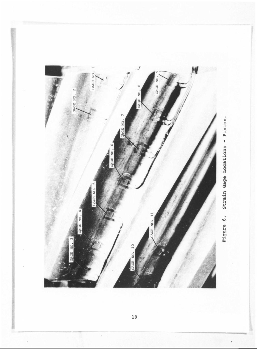
29 STRAIN SURVEY In order to evaluate the load-carrying capability of the conformal gear, it is necessary to understand the nature of the load-sharing and concentration, as the teeth rotate through mesh and under load. To accomplish this, three consecutive pinion teeth were gaged in such a way that records of load-sharing were obtained as the gear and pinion were rolled through mesh under load. The application of torque and direction of rotation were identical to the load test runs. INSTRUMENTATION Strain gages (type C6-111) were applied to the tension root fillet of the pinion. Figures 6 and 7 show the gage placement and position by numbered location. Resistance calibration methods were used to establish a known strain level in each gage. Gage locations with respect to distance from the pinion pitch diameter were held within inch of each other. The gages did not extend into the contact surface of the teeth. Seven gages were applied to the middle tooth at equal spacing of , with gages numbers 3 and 9 as close as possible to the tooth ends. Gages numbers 1 and 2 were applied to the preceding tooth with the same spacing between gages. Gages 10 and 11 were similarly applied to the entering side of the succeeding tooth. Additional information was obtained from a rotary potentiometer connected to the pinion shaft and from a continuous record of the gear torque. PROCEDURE The test procedure was to rotate the pinion and gear slowly through mesh, while observing and recording strain gage outputs, torque, and angular position. The first roll-through was accomplished with the pinion as the driving member. The second roll-through was achieved with the gear driving and returning to the original starting point. The driving member is the one where the loaded side of the tooth is advancing with respect to direction of rotation. In normal speed decreasing drive, the pinion is driving. This was the condition prevailing during the actual test runs under load. All of the data were recorded on a multichannel oscillograph while the gears were rotated through mesh. 18
30

31 Figure 7. Strain Gage Installation - Pinion. 20

32 RESULTS A typical record of test results is shown in Figure 8. Outputs of gages 1 through 11 are shown as they rise and fall during the meshing cycle. The middle tooth is in mesh from the first rise of gage 9 to the return to zero of gage 3. The return to zero of gage 10 indicates the instant of disengagement of the first tooth. The rise of gage 2 indicates the engagement of the third tooth. The interim period is when the middle tooth carries all the load. The period of single-tooth engagement was found to be of very short duration (Figure 9). The left-hand peaks were obtained with the pinion driving; the right-hand peaks were obtained in reverse with the gear as the driving member. During the meshing cycle, strain amplitudes were found to be consistently higher with the pinion driving. This result is in agreement with the testing accomplished in USAAVLABS Technical Report Variations in the torque trace were observed and recorded during roll-through. The maximum variation shown is less than 1 percent of the total applied torque. Torque variations did not appear to repeat in a cyclic pattern and were not clearly identifiable with other rotating components. Maximum strains at each gage across the pinion face are recorded in Table IV. Two test conditions are shown. Strain outputs by a particular gage may be affected by variables such as gage location, inclination, and bonding of the gage to the specimen. With this in mind, the trends and directions of the maximum strain at each gage across the pinion face width compare favorably with the results presented in USAAVLABS Technical Report 66-8 (see Figures 10 and 11). The two test conditions for the strain survey were conducted at 100 and 150 percent of the design load. Results indicate that the maximum strain level for the same gage location is approximately proportional to the increase in load level. Gage number 3 (on the exiting end of the middle tooth) recorded a strain 48 percent lower than gage number 9 (on the entrance end of the middle tooth). This condition may be partially responsible for the tapered patterns, larger width at the entrance end, and tapering to a smaller width at the exit end. It is reasonable to expect that an increased strain can result in more area in contact and a larger pattern. 21
 o S id M 4J en M o id M H 1")
33 id P S s. IT) o S id M 4J en M o id M H 1 H Ü 0) O 00 I H CM 22


34 p ü 0) «w «4-1 W c H 8* rh O 10 9\ I I I O O O O O O o o«oo r^ \o IA % NIVHiS 23

35 TABLE IV. STRAIN GAGE SURVEY DATA (SK , PINION; SK » GEAR) NAximum Amplitude Maximum Strain 1 (inch) (Micro i In./in.) 1 1 Gage No. Pinion Gear Pinion Gear Driver Driver Driver Dr iver I Run No. 1-21, 800 Inch- Pounds Torque i ^ j 1! Run No. 3-32, 550 inch- Pounds Torque j i


36 GAGE NUMBER, 1 ^ ;' X u z H \ en u ac u ss H u z H CLOCKWISE ROTATION ^» EXIT 4 1 k < \» \ ^ / \, ( ENTE ANCE- PIN: ON DF IVEN l EH < t i J 1 < i 5 > 4 GA 6E NU MBER t : 1 Figure 10. Maximum Strain at 21,800 Inch-Pounds Torque, 25
 \ / ON DF IVEN \ t ENTR ANCE ^ 11 10 7 6 5 4 3 2 GAGE NUMBER Figure 11.")
37 g z H \ Ui w s ss u H s I z ( / / 1 r i T i i, k COUNTERCLOCKWISE ROTATION 1 j \ 1 N V > k / \ / 1 / / PINION DRIVER L PKPFB ANCE EXIT< 1 ( s, 2 3 ^ I I > > ' 6 > GAGE NUMBER g Z H \ u z H I z S ( III 1 1 CLOCKWISE ROTATION s ( PINI EXIT L > V \ ) \ / ON DF IVEN \ t ENTR ANCE ^ GAGE NUMBER Figure 11. Maximum Strain at 32,550 Inch-Pounds Torque. 26


38 COMPARISON OF STRAIN SURVEY RESULTS WITH RESULTS IN USAAVLABS TECHNICAL REPORT 66-8 Comparison of the results of this strain survey with the results of the strain survey accomplished during the previous contract indicates that the current SK16207 conformal gears recorded larger strains. Load levels for the two programs were not the same; the present loads were 1.42 times greater than those for the previous program. The resulting maximum strain readings were 1.84 times greater for the current program. This can be attributed to the fact that the present tooth form has a larger radius of curvature and more tooth height. The ratio of the minimum strained and maximum strained axial sections is in the order of two to one. This result closely correlates with the results of the previous test program where the tooth geometry was different in some respects to the present test gears. Comparison of the results of both strain surveys indicates that the pattern across the tooth has a much higher strain at the entrance end. This is in agreement with the tooth pattern checks made during both programs. These checks indicated a larger load concentration at the entrance end as evidenced by the tapered pattern (heavier at the entrance end of the mesh). 27

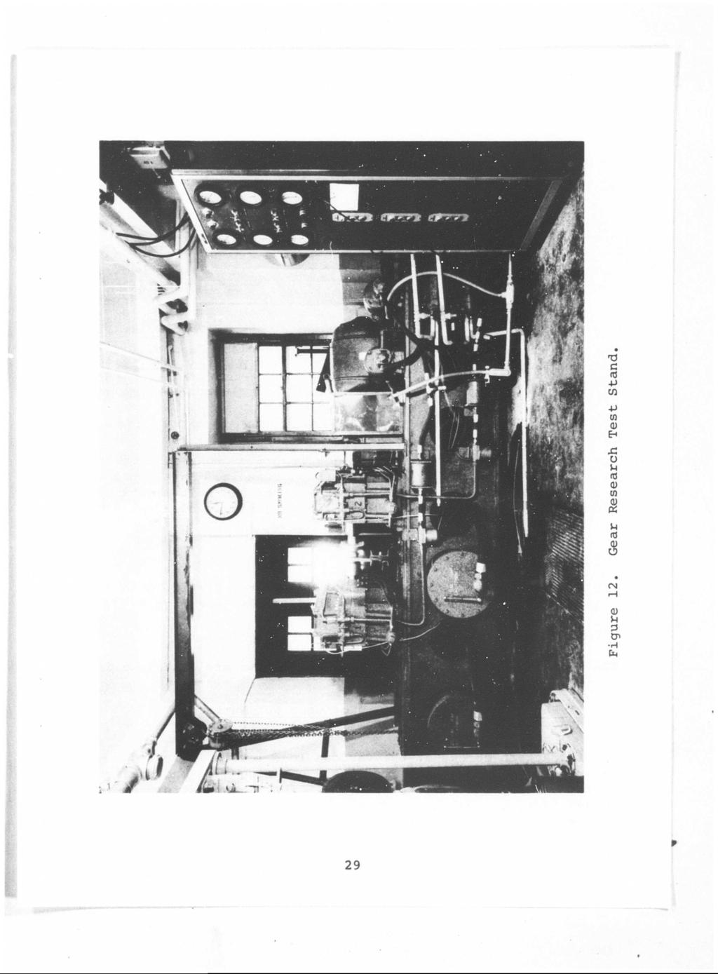
39 LOAD TESTS EQUIPMENT Testing was conducted in a Vertol Division-owned regenerative (four-square) load test stand built specifically for gear research (see Figure 12). The two gear housings are designed to be rigid and stable under all loading conditions. Housings were through-bored for maximum accuracy. Torque, rpm, ond lubrication can be varied over a wide range. Acceleroraeters were attached to both the slave and test gearboxes and connected to a dual-channel oscilloscope. Changes in vibration signatures for both gear housings can be observed simultaneously and used as an indication of impending gear failure. Each gearbox lubrication system includes an individual reservoir«pump, control, indicators, filler, and jets. All controls and indicators are mounted in the console. Lubrication oil volume is controlled by a bypass valve. Temperature is measured both in and out of the test gearbox. Pressure is measured at a point just upstream of the jets. Atlantic Refining Company Premier 12 gear lubricant was used throughout the test program; it contains extreme pressure additives in the form of lead soaps. Vertol Division has used Premier 12 in previous gear research testing.* Lubrication was provided by oil jet on the out-of-mesh side. The flow rate was approximately 2.0 gallons per minute. Lubricant pressure, temperature, and viscosity were controlled to the following values during the tests: 1. Operating Temperature: 130 ± 15 0 F Oil In 2. Operating Pressure: 50 ± 15 psi 3. Viscosity at Operating Temperature: 300 SSU * Mack, J.C. f D'Angelo, B., EVALUATION OF THE EFFECT OF GEAR TOOTH GRINDING METHODS ON FATIGUE LIFE OF SPUR GEARS, Boeing Document No. R-342A, the Vertol Division of Boeing, Morton, Pennsylvania, August i '
40 29
, The procedure for this test program was to check torque after 30 minutes of running, then to recheck every 4 hours during the")
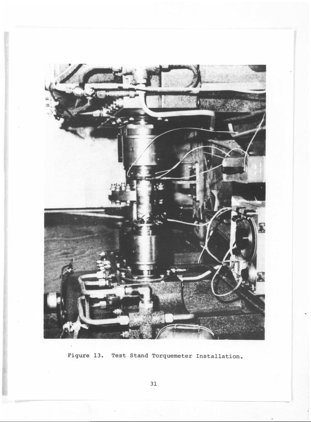
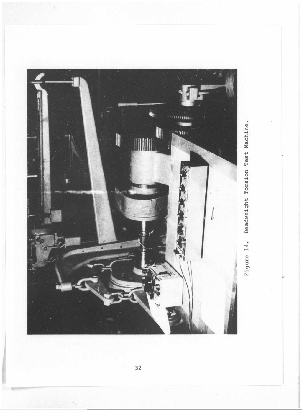
41 Variables The primary test variables were shaft torque and test cycles (time). Gear load is a function of shaft torque. Torque Torque was applied with a lever system at the beginning of each test run. Torque levels were observed on a Strainsert instrument (see Figure 13), The procedure for this test program was to check torque after 30 minutes of running, then to recheck every 4 hours during the test. Deviation from the initial target torque was held to + 5 percent. The torquemeter shaft was calibrated before and after the test series on a deadweight torsion test machine (see Figure 14). The same instrument was used during the calibration and testing, Recalibration curves agreed with the initial curve within 2 percent. Test Cycles Test cycles were determined by a log record of running time and an elapsed time meter in the test stand console. An electric motor driving the input shaft through a toothed belt maintained pinion speed at 3660 rpm (219,600 tooth-loading cycles per hour). Procedure At the initial installation of both gear sets, static tooth patterns were recorded at various load levels (see Figure 15). RESULTS The complete results of the load test program are contained in Table V. Static Pattern Check and Run-in of Gear Set Number 1 (SK , Pinion and SK , Gear) Static pattern checks at the various load levels indicated a tapered tooth pattern, larger at the entering side and smaller at the exiting side (see Figure 16). The pinion pattern extended further down the tooth flank than did the gear pattern. The gear tooth pattern was at or beyond the break edge radius 30
42
43

44 Figure 15. Installation of Conformal Gears - Static Pattern Checks. 33 p

![37 4,475 Tapered patternl mild scoring Run No. 1 6.0 2.53 8,410 Tapered patternl slight increase] in scoring Run No. 2 6.0 2.53 12,380 Tapered F^tternj small improve- 1 ment in scoring!](/docs-images/93/114430353/images/45-2.jpg "(healing over) 1 Run No. 3 2.987 l.->o 15,610 Tooth failure, gear member Target load levels established for the program were: 1. At 100-percent design 8450 inch-pounds. 2. At 150- percent design 12,675 inch-pounds.")
45 TABLE V. LOAD TEST PROGRAM pest Run Stress Cycles Pinion Torque (mill.ions) (inch-pounds) End Condition 1 Pinion Gear SK16207-: t SK Set No. 1 Run- in ,380 Tapered patternl Run No ,760 Tapered patternl Run No ,650 Tapered patternl Run No ,850 Tooth failure, gear member ] Set No. 2 Run -in ,475 Tapered patternl mild scoring Run No ,410 Tapered patternl slight increase] in scoring Run No ,380 Tapered F^tternj small improve- 1 ment in scoring! (healing over) 1 Run No l.->o 15,610 Tooth failure, gear member Target load levels established for the program were: 1. At 100-percent design 8450 inch-pounds. 2. At 150- percent design 12,675 inch-pounds. load, pinion torque was load, pinion torque was 1 3. At 175- percent design 14,788 inch-pounds. load, pinion torque was I 34
 did not reveal any adverse conditions in regard to surface distress (see Figure 17a).")
46 at the outside diameter, at the higher load levels. Visual inspection after the initial run-in (at 50 percent of the design load) did not reveal any adverse conditions in regard to surface distress (see Figure 17a). Load Test Runs of Gear Set Number 1 Test Run Number 1 Run number 1 was completed at 100 percent of the design load for 6 million pinion cycles. Visual inspection at the completion of this run did not reveal surface distress. There was some evidence of an improvement in the tooth pattern. Taper at the entrance and exiting ends was less pronounced (see Figure 17b). A close examination of the tooth patterns revealed a local heavy bearing area on the lower end (entrance side) of the pinion and along the top of the gear member for the full length of the pattern. Test Run Number 2 Run number 2 was completed at 150 percent of the design load for 6 million pinion cycles. Visual inspection revealed that at the lower portion entrance side of the pinion, there was an indication of a secondary local heavier bearing area within the original pattern, approximately 0.4 inch in length and 0.03 inch wide (see Figure 17c). On tfte gear member, the secondary local bearing area was apparent just below the break edge, at the outside diameter for the length of the original pattern. Patterns on the gear member ended approximately 0.05 inch short of the end of the gear at the exit side. Visual inspection of both members did not reveal any indications of surface distress. Test Run Number 3 Run number 3 was conducted at 175 percent of the design load level. This test run was terminated at 3,623,400 pinion cycles, due to bending failure of one tooth on the gear member. Subsequent Magnaglo inspection of this gear member did not reveal any other teeth with failure indications. Vertical scratches on every other tooth profile of the pinion members (in the first inch of face width) were attributed to the tooth failure on the gear member. Magnaglo 35
 \"T LOCALIZED HEAVY BEARING h-.oe GEAR.13 (DRIVEN) ENTRANCE SIDE 50% TORQUE PINION.20 (DRIVER) T LOCALIZED HEAVY BEARING GEAR «*-. (DRIVEN) T ^[-^.")
47 STATIC GEAR PATTERNS - GEAR SET #1 PINION-P/N GEAR-P/N SK , S/N 1 SK162Ö7-4, S/N 1 PINION (DRIVER) Ti 16 ^^OTSSI GEAR -j- (DRIVEN) f»«ih-.oe -^-i.50-fc ENTRANCE SIDE LIGHT LOAD PINION «18 (DRIVER) "T LOCALIZED HEAVY BEARING h-.oe GEAR.13 (DRIVEN) ENTRANCE SIDE 50% TORQUE PINION.20 (DRIVER) T LOCALIZED HEAVY BEARING GEAR «*-. (DRIVEN) T ^[-^.06 [*_-!.53» ENTRANCE SIDE 100% TORQUE Figure 16, Static Gear Patterns - Gear Set No, 1. 36
 LOCALIZED HEAVY BEARING I r HEAVY BEARING-s I ENTRANCE SIDE AFTER RUN #1 100% TORQUE GEAR (DRIVEN) ft-.045 LOCALIZED HEAVY BEARING PINION (DRIVER) GEAR (DRIVEN).02 -.")
48 GEAR PATTERNS AFTER RUNNING - GEAR SET #1 PINION-P/N SK162Ü7-3, S/N 1 GEAR - P/N SK , X S/N 1 PINION (DRIVER) Li * LA ENTRANCE SIDE AFTER RUN-IN e 50% TORQUE GEAR (DRIVEN) -* K-.06 PINION (DRIVER) LOCALIZED HEAVY BEARING I r HEAVY BEARING-s I ENTRANCE SIDE AFTER RUN #1 100% TORQUE GEAR (DRIVEN) ft-.045 LOCALIZED HEAVY BEARING PINION (DRIVER) GEAR (DRIVEN) ^HEAVYBEARING^.16 CV.W...V. Y.;;;X..;...;.;.;.J T -HK T ENTRANCE SIDE AFTER RUN « % TORQUE Figure 17. Gear Patterns After Running - Gear Set No, 1, 37
 Static Pattern Check and Run-in Gear Set Number 2 Static pattern checks at the various load levels indicated a tapered")

49 / inspection of the pinion did not reveal any cracks. Approximately 20 minutes before failure, there was an increase in signature amplitudes and a change in the original pattern. Load Test Runs of Gear Set Number 2 (SK , Pinion and SK , Gear) Static Pattern Check and Run-in Gear Set Number 2 Static pattern checks at the various load levels indicated a tapered pattern at both the entering and exiting ends (see Figure 18). At the 100-percent load level, this condition was not as evident as the result at the lower load level. The pattern on the gear member moved out to the break edge at the outside diameter at the higher load levels. Visual inspection after the initial run-in (50 percent of the design load) revealed very light scoring on both pinion and gear members (Figure 19a). Test Run Number 1 Run number 1 was completed at 100 percent of the design load for 6 million pinion cycles. Visual inspection upon completion of this run revealed a slight progression in the scoring condition at the completion of the 4-hour run-in. Some improvement in the tooth pattern was noted. The taper at the entrance and exiting ends was not as pronounced. There was a small, heavy bearing area at the exit end of the gear member, approximately 0.3 inch wide, running vertically along the tooth flank (Figure 19b). Test Run Number 2 Run number 2 was completed at 150 percent of the design load for 6 million pinion cycles. Visual inspection upon completion of this run revealed a slight improvement in the scoring condition (healing over). On the gear member, there was an indication of a secondary local heavier bearing within the original pattern at the entrance end of mesh (Figure 19c). Test Run Number 3 Run number 3 was conducted at 175 percent of the design load level and was terminated at 2,986,560 pinion cycles, due to a bending failure of one tooth on the gear member. 38
 ' 18 9^^^^^^ GEAR.13 (DRIVEN) -T- ENTRANCE SIDE 50% TORQUE.065 ±± PINION.18 (DRIVER) T ± GEAR.13 (DRIVEN) T.07 *mmmm f fmrnm^mmmi 1.1.22 T ±.")
50 STATIC GEAR PATTERNS - GEAR SET #2 PINION - P/N SK , S/N 2 GEAR - P/N SK , S/N 2.05 PINION JL J. (DRIVER) -J^ GEAR -L rj 1 (DRIVEN)»J^ ENTRANCE SIDE LIGHT LOAD PINION -fr _.,,,,. jili,,, "- (DRIVER) ' 18 9^^^^^^ GEAR.13 (DRIVEN) -T- ENTRANCE SIDE 50% TORQUE.065 ±± PINION.18 (DRIVER) T ± GEAR.13 (DRIVEN) T.07 *mmmm f fmrnm^mmmi T ±.14 T ENTRANCE SIDE 100% TORQUE Figure 18. Static Gear Patterns - Gear Set No
 ENTRANCE SIDE AFTER RUN-IN @ 50% TORQUE PINION (DRIVER) GEAR (DRIVEN) HEAVY BEARING. 2 5 ~n p\" ENTRANCE.05 SIDE ^ **-1.00-^ i r.")
51 GEAR PATTERNS AFTER RUNNING - GEAR SET #2.07 PINION - P/N SK , S/N 2 GEAR - P/N SK , S/N 2 PINION 20 (DRIVER) GEAR.14 (DRIVEN) ENTRANCE SIDE AFTER 50% TORQUE PINION (DRIVER) GEAR (DRIVEN) HEAVY BEARING. 2 5 ~n p" ENTRANCE.05 SIDE ^ **-1.00-^ i r.17 "T AFTER RUN 100% TORQUE Li 7 PINION (DRIVER) 111 *,04 i.04 LL T ^ -*- T GEAR i i ENTRANCE SIDE 16 (DRIVEN) T ^^i^^:^««^.17 T LOC..>!ED VU~1.25 HEAVY BEARING I AFTER RUN 150 % TORQUE Figure 19. Gear Patterns After Running - Gear Set No. 2, 40


52 1 3 Subsequent Magnaglo inspection of the gear member did not reveal failure indications on any other teeth. The vertical scratches on every other tooth of the pinion member in the first inch of face width were attributed to the tooth failure of the gear member. Magnaglo inspection of the pinion did not reveal any failure indications. A change in trace trends on the oscilloscope were seen prior to failure. They were similar to the trends seen on the first test set. METALLURGICAL FINDINGS The metallurgical analysis of gear sets numbers 1 and 2 made upon completion of testing included the following (Figures 20 through 31) : 1. Nital Etch Examination Nital etch examination showed no evidence of grinding damage on either gear set. 2. Microhardness Traverse A microhardness traverse was made on the failed tooth of the gear member of both sets. The results are plotted in Figure 32. The effective case depth of the gear from set number 2 was inch over the drawing specifications. 3. Microexamination A microexamination for retained austenite, carbide network, and cleanliness showed that the material was satisfactory in all respects. 4. Fractographic Examination A fractographic examination of the failed tooth of gear member set number 1 located the origin of fatigue to be on the drive side of the fillet. The failure origin was located on the surface approximately at the juncture of the profile radius and the undercut. A fractographic examination of the failed tooth on the gear member of set number 2 also located the origin of fatigue on the drive side of the fillet. The origin was subsurface, approximately inch below the junction of the profile radius and the undercut, and inch below the surface (Figure 33). 41
 55 ^ u, O O O^j jg f\j H <- 1 3 ro X)")
53 Pc 3 «-a <c o 03 2 O H z H a. o 2: P a; w n I r* o (N < > * ft CO (N c H fa I Q) 55 ^ u, O O O^j jg f\j H <- 1 3 ro X) rh H W Q) «ft C «, CO O e H ft P CO a) EH o (N Q) M 3 H ft 42
 o tn 0 J-l r 1 < u w CM 0) u 3 Cn H Cn I o CM VD (d 5")
54 x; -p 0 o En T) <D M a 3 H -P 01 O H <t) u M o fa U) 4-1 <u O -p n3 s U QJ H H > c H a 3 s a) o tn 0 J-l r 1 < u w CM 0) u 3 Cn H Cn I o CM VD (d 5 43
 u w")
55 J O US U <D as Xj 0) P 3 H 5 -H -P (0 (0 0) < tj> c C -H H -P D> O -H C n a> O Q r vw <N >-i o O 2 U-l C -P o a) u w 44
 u C/J nj 0 Q) M <u < M 3 C -P H u CP 3 H M -P o U1 * 0 CM a H a 0 z 0) w -p (fl Q) u w m O rt Q) a n 3 o tn o -H in t, u tri (N i 2 3 O O -H in 45")
56 4-1 ifl o a) H 0) < n 3 c p H u tr> 3 H M o 01 o 1 i o H a o z <u -P o <D u CO o m (U M 3 P> H fa 4-1 (0 0 <u M 0) < M 3 c -P H O tr> 3 H M P O tn 0 ' 1 u H a O Z <D tn -P (0 d) u C/J nj 0 Q) M <u < M 3 C -P H u CP 3 H M -P o U1 * 0 CM a H a 0 z 0) w -p (fl Q) u w m O rt Q) a n 3 o tn o -H in t, u tri (N i 2 3 O O -H in 45
57 ELMR EFFECTIVE CASE DEPTH - SET 1 EFFECTIVE CASE DEPTH - SET 2.046".059" 64.0 I 800 LOCATION AT DRIVE FILLET 60.1 SET g 40.8 a< 400 «29.8 O 300 SET DEPTH BELOW SURFACE (IN.) Figure 32. Graphical Analysis of Gear Sets Nos. 1 and 2 for Effective Case Depth Evaluation. ORIGIN Figure 33. Origin Location of Failed Tooth Gear Member - Set No

58 DISCUSSION OF TEST RESULTS Ar> a result of the problems encountered in the previous test program (USAAVLABS Technical Report 66-8), the following design changes were incorporated in the current test gears: 1. The profile radius was increased by 100 percent on both the pinion and gear. ' 2. The profile mismatch was increased between the pinion and gear by 100 percent. 3. The pinion member of one gear set was crowned to inch. By increasing the profile radius on both members, the surface contact area was also increased. This design change resulted in a substantial improvement in surface load capacity of the current test gears as evidenced by the lack of any pitting at the 175-percent load level. The combined effect of the increased profile radii and increased profile mismatch resulted in a solution to the tip impingement problem on the pinion member of the previous test gear sets. In addition, the effect of heavy load concentration at the entrance end of engagement was diminished for the load levels tested. Gear set number 1 successfully completed a load run of 150 percent of the design load for 6 million cycles. During the testing of this set, there were no indications of surface distress evident at any time. The detrimental condition of entrance distress experienced during previous testing (USAAVLABS Technical Report 66-8) was not evident in this test set. Set number 2 successfully completed a load run of 150 percent of the design load for 6 million cycles. During the testing of this set, mild scoring was evident at the lower load levels. This condition healed over at the higher load levels and may be attributed to the lead relief (crowning) present on the pinion. At the lower load levels, tooth deflection was not sufficient to allow the entire face width to accept load; however, entrance distress was not evident on this set. 47
, both sets of test gears experienced surface distress (pitting) at a load level approximately equal to the 100-percent load level as established for")
59 Failure of both sets numbers 1 and 2 (one tooth on the concave gear member) at 175 percent of the design load was attributed to a fatigue failure in bending on the drive side in the fillet area. In the previous program (USAAVLABS Report 66-8), both sets of test gears experienced surface distress (pitting) at a load level approximately equal to the 100-percent load level as established for the test gears in the current program. Visual inspection of the former test gears revealed a heavy load concentration at the entrance end of engagement where pitting was first encountered. A tooth bearing pattern which tapered toward the exit end of engagement was further evidence of this load concentration. In addition, tip impingement by the gear member occurred in the vicinity of the root on the pinion, resulting in a heavy localized bearing. The gear member with concave profiles failed in bending. Since indications of surface distress were not present on the pinions or gears at the conclusion of testing, it is evident that the current design favored contact strength capacity. In any future designs, it will be necessary to redistribute tooth thickness to favor the gear member in order to obtain a better balance between bending and contact strength capacity. Although significant design improvements were achieved in the current test gears, the tapered tooth bearing patterns which were encountered in the previous test gears were also evident to a lesser degree in the current gear sets. On the basis of load concentration at the entrance end of engagement, strain gage survey results, and tapered tooth patterns as experienced on the previous test gears, one of the current test pinions was crowned (SK ). The test results of gear set number 2, with the crowned pinion, did not indicate an improvement over that of set number 1. At the beginning of load running, set number 2 encountered light scoring on both members. However, operation at the higher load levels resulted in a healing over of the initial scoring condition. Scoring at the lower load levels may be attributed to the pinion crowning. The teeth may not have deflected sufficiently to fully load the crown ends, thereby resulting in a concentration of load in the remain! ig face width. The effect of crowning on entrance distress and tip impingement cannot be definitely ascertained because both gear sets (crowned and uncrowned) successfully operated without encountering these problems. 48

60 In order to provide a better understanding and possible solution to the tapered tooth patterns, the following investigations were made: 1. Inspection of the test box bores for alignment, concentricity, and center distance was made and found to be within the drawing tolerances. Center distance and runout checks were made with the test gears and couplings installed in the test stand. The results indicated that these parameters were within acceptable limits. All of the inspections were performed by the Vertol Division's Quality Control department. 2. Shaft deflection and gear face runout were inspected during the static pattern checks and were found to be negligible. 3. Lead-error checks of both gear sets indicated that deviations were within inch across the entire face width, 4. The conformity of the pinion profile radius was inspected utilizing the special inspection fixture; it was found to be within inch (on the drive side) across the entire face width. These results indicate that all parameters are within acceptable limits; therefore, their effect on the tapered pattern condition may be considered negligible. The strain gage survey indicated that gage number 9, located on the middle tooth at the entering side, had approximately 80 percent more strain than gage number 3 at the exit end of the same tooth. This result was repeated for both load levels tested. An explanation for differences in the amount of strain at the ends of the middle tooth may be in the amount of tooth material available for backing. At the extreme entrance end, the helix angle limits the backing material available at the load point to approximately one-half of the tooth thickness. When the load shifts to the exit (opposite) end, the helix angle has no effect, since the full tooth thickness is available for backing behind the load; therefore, it appears reasonable to assume that the patterns at the entrance end would be heavier than at the exit end. Figures 34 and 35 reflect the bending and contact stress levels for a comparable involute gear, with the same pitch diameter, 49 -^ifrtmm»»«*"
 per the appropriate Vertol specification.")

61 number of teeth, diametral pitch and face width. However, in good design practice, 16-tooth involute pinions are not normally used. A finer pitch with more teeth would be standard practice. The bending stress resulting would thus be higher than is shown in Figure 35. The teeth on all the test gears were shot peened (flanks and fillets) per the appropriate Vertol specification. The effect of shot peening primarily is to increase the residual compressive stress at the fillet. However, visual examination of the test gears Indicates that the shot peening coverage in the fillet area of the gear member could be improved. This may be attributed to the inaccessibility of the root area to the shot and the effect of shot reverberating from the flanks, thereby blocking the path to the root. In future designs a reciprocating wand directly in the undercut area will vastly improve the shot distribution in the fillet area. An indication of gearing efficiency may be obtained by a comparison of the temperature rise of the lube oil and oil flow of the slave box and the conformal test box. The heat generation in the conformal test box was 13 percent lower than the heat generation in the involute slave box. This result appears to indicate an improved efficiency for the conformal gear as compared to the slave (involute^ gears. This is in agreement with the analytical predictions of improved efficiency for the conformal tooth form, due to a constant sliding velocity, as contrasted to a variable sliding velocity for the involute tooth form. 50 ja*
 Q 110\" in in 100\" 90 Figure 34 in 1 -»- + H + t- + -»- - - 7 8 9 10 11 12 13 14 15 PINION TORQUE - INCH-POUNDS X 10 3 Involute Contact Stress Levels at Pitch Liae Vs Torque. 51")
62 230T 220' Results of Conformal Test 3 x 10 Cycles 4- o X CO CO EH CO o < > Results of Conformal Test 6 x 10 Cycles ä 150 Z o u 140" M Ö " I I l 'i s d c H 0) Q -o c m 0) Q 110" in in 100" 90 Figure 34 in 1 -»- + H + t- + -» PINION TORQUE - INCH-POUNDS X 10 3 Involute Contact Stress Levels at Pitch Liae Vs Torque. 51
 o in 20 I 6 T 7 T 8 I 9 T 10 11 T 12 13 PINION TORQUE - INCH-POUNDS X 10 3 14 15 Figure 35. Involute Bending Stress Levels Vs. Pinion Torque.")
63 x 10 Cycles Results of Test I 60- H m 6 x 10 Cycles Results of Test o SO- (0 (0 i x 10 6 Cycles Result ults of Test j J G H (0 o a' "I ^1 -a 0 c to 0) o in 20 I 6 T 7 T 8 I 9 T T PINION TORQUE - INCH-POUNDS X Figure 35. Involute Bending Stress Levels Vs. Pinion Torque. 52

64 CONCLUSIONS 1. The conformal test gears successfully demonstrated a load-carrying capacity equal to 150 percent of the established design load. 2. Inspection techniques have been determined which are % capable of providing dimensional control of conformal gears commensurate with that of aircraft involute gears. 3. Load-carrying capacity can be improved by a better balance of contact and bending strength and modification of the following respective design factors: Reproportioning the tooth thickness of the pinion and gear members to improve the balance between contact and bending strength, relieving the entrance end of the pinion tooth face by machining at an angle at the ends of the teeth, thereby eliminating the condition where entrance load does not have the full tooth thickness as backing, and increasing the outside diameter to prevent the tooth bearing pattern from shifting over the top land break edge, at the higher load levels. 4; The gear member was the weaker member in bending. 5. The contact stress which was attained at the failure load level was approximately 36 percent higher than the design load (which represents normal operating design practice). It should be noted that the test gears were operated in a rigid test stand using an oil containing extreme pressure (E.P.) additives. 6. Failure of both test gear sets was attributed to a bending fatigue failure in the fillet area. The tooth surface condition of the test gears at the conclusion of the final runs indicates that the upper limit for contact strength capacity had not been attained. 7. Both test pinions (with and without crowning) in this test program operated without developing indications of entrance distress as experienced during the first program. i 53...uWJ* a»«*

65 8. Realization of the full potential of the conformal gear for application to helicopter speed reduction gear drives will require extensive design and development programs to ascertain the effects of the following design factors; a. The relative radius of curvature for maximum pitting resistance b. The effect of axial overlap on load capacity and noise level c. The maximum difference in profile curvature mismatch between pinion and gear to accommodate a suitable center distance tolerance and still provide maximum load capacity d. The effect of pressure angle on both bending and contact strength Determination of the effects of these design factors may require three-dimensional photoelastic analysis, single tooth bending fatigue testa additional rotating surface fatigue tests, and additional strain surveys of rotating teeth. 54

66 APPENDIX NOISE LEVEL TESTS - CONFORMAL GEARS INTRODUCTION As a further effort in the evaluation of the conformal tooth form, the Vertol Division of Boeing conducted a noise measurement program in August 1967 at the Villanova Department of Mechanical Engineering Gear Laboratory to evaluate the effects of gear tooth design on radiated sound pressure levels. The gear set evaluated was of conformal profile and 4,5 diametral pitch. These gears were run simultaneously with 9.0 diametral pitch finish ground involute spur slave gears (to aircraft standards) with the same pitch diameters in a pretorqued configuration. Although this experimental arrangement was preliminary in nature from a noise measurement standpoint, some useful information was obtained. PROCEDURE In order to isolate the noise of each gearbox, an acoustical enclosure was constructed of 1/2-inch plywood (see Figure 36). The box was lined with aircraft-type blanketing to increase the sound transmission loss and to provide a semifree field environment within the enclosure. All measurements were made by inserting the microphone through predrilled openings in the walls of the enclosure. When the survey on the slave box had been completed, the enclosure was transferred to the conformal gearbox and the survey repeated, RESULTS AND CONCLUSIONS Data were obtained at 100 percent of the design torque for both gears. An analysis of the noise at two locations for each gear configuration (midposition on the top of the box and an inboard side location) was performed on a wave analyzer using a 3-Hz filter, at 0,5-inch-per-«inute chart speed, and 3-inch-persecond writing speed. Although the gear mesh frequency of the spur gears was twice that for the conformal set, some general conclusion? may be drawn. At the third hamonic conformal gear mesh frequency and below, the conformal gears display larger amplitude noise levels than the spur gear set (see Table VI). Above the third harmonic of the conformal gears, the level of the spur gear generally exceeds the conformal, and at integer harmonics it is as much as 20 db higher. The odd harmonics of the spur gear»correspond to the midpoint between conformal 55

67 Sc: O CO CM r» in <H <o «o i P- ^1 00 o * O a «n m i^ ^i o * * o «a r» in N t» * a l ic * r* o CD in ct «M n to ^ o n 0i m i» a co in N r» M a 1 in H «o S a O» H m M t o» in m O a r> as CO O a + «i-i m o Ol Q U 5S Ct CO ^ l ^ 5 m o a< m in 5 o OB SO CO «> c; B o r» * r- CO a at co a Q N to m o CO S i* * <= fm in M > o to oi n H «M o O» a a ^ rh r-l «(M + a J5 o < a -H m t o 00 0t ih i0 es a 00 Ot -1 9 (S»H (D Q s * H u -4 A H S 3 Freq Spur Conf S H 4i I Level ormal e Spur Spur Conf db r CM o in m m 10 CO» o r» i» + in o m 5 CM in fl i-l ih at co l o o ( > * rh 00 CO * + o in m m i-t o tn tn m i-t o in o t m co r> O Ot H o t~ r- O m m CM o in m to in Ot ot o (N i o 00 H m l 00 I» tf to o m in O H H CO m m o O * CM r«r» o CO 00 + m m in r» o» as o to >-l fl co r~ T«H o m ro O H to in in to O «CM * * W ih CM i-l O O O H in CM «H H CO CO 1 in H u >«a (M (> Ot PH o. * O 0» s PH < + ij in oo m r- O Ot ih r> 00 g to 3 S + O 00 M 1 Q o m in o 2 o in in r- CM a H 00 CM m ot ot 00 Ot + cn + w i m in CM O to m in o o «(0 00 O -f in in n CM <M o 00 Ot CM ot ot + g in m CM o in in rh H m f-i o o * IM CM Ot 00 1 o o ^ rh o o o in m * o in in cn, in 00 CM + to cn oo m i 1- OO H Ot ot H H > in in O in m CM O in i * n in r-i CM cti o 1 r» f» + ft Ot 0> m in in CN o n r- * *-< o Ot ot fn r- ct + r» co O CM H + in in in Ot -H CM O *. CM u O 00 u H a 4 u g H s 3 i s o E H SS g tl <M ä Level mal Spur Spur Con fa db re s H «1 CM &l H H I 00 cn O 00 1 Level mal Spur Spur Con fa db re CM 56
![PZZZgZZZZZZSPI QzzzzssmzzsBam R-^]t ^rt v TOP VIEW ACOUSTICAL ENCLOSURE CONFORMAL GEARBOX INTERCONNECT SHAFTING](/docs-images/93/114430353/images/68-2.jpg "DRIVE MOTOR SIDE VIEW Figure 36. Schematic of Gear Teat Stand Showing Installation of Acoustical Enclosure.")
68 PZZZgZZZZZZSPI QzzzzssmzzsBam R-^]t ^rt v TOP VIEW ACOUSTICAL ENCLOSURE CONFORMAL GEARBOX INTERCONNECT SHAFTING DRIVE MOTOR SIDE VIEW Figure 36. Schematic of Gear Teat Stand Showing Installation of Acoustical Enclosure. t 57

69 harmonics and display levels well above conformal gear noise at these frequencies. The wave analysis for Location 2 is shown in Figure 37. No attempt was made to determine if any of the reported levels were a direct result of the gear case response at or near a natural frequency. The assumption is made that this was not occurring. A comparison of one-third octave band analyses for each gear configuration is shown in Table VII for Location 2, a typical location. This also illustrates the higher levels produced by the conformal gears in the low frequency spectrum and the generally lower levels produced by the conformal profile above 1000 Hz. Due to the many variations in noise level which can occur owing to effects associated with the test setup and not with the gears themselves f the results of the program described here should be treated as a trend and not as absolute information. However, additional data would serve to confirm these results. 58


70 --* -- l" a 110 "- _J _L. - - ::. : J ri: - _ - SPUR GEAR LOCATION NO, 2 HORIZONTAL sc 1 _.. i 1 :i ^ - : : - ^ -'-' "Z "E ~ --"' E 1 ~1~ = ~ _ - - E '~ o i i i I 100 TOOTH FREQUENCY -T :: - 3 : : 3 t:z ~ :~ - ** E ;_.: - : - ~ -+- : : - : J 90 "* 1 ^ -.":. z = : ; '-'-, 1... :: 1.. V g i ^ (/) ^ " - E r; E 1 " : - : : ± " ~ E M t rl - 1 K M '- ^^ - ft ; s * If 1 ill t M HMML-I r E ki a - llffm i d hj z: i _ i ~ * e?, W Mil 1 _ U-l, #l_j 1 (-» DU [IB nnr l w r ii If ft i\ *+ i M ^ ^i n. jui L + IiMl 1 Ä^ SI 'm?i ^Hl tmm. 1 i, uniiiinibj Mt»JHU.M B.HiM. 41 Ull-BUJLlH-IIW Jkl. Ill IM ii mmmnnmimn 1H Mt J ft ^O l-hlimiillmh^f-ll H^V-^H n P -H F HHI '1 I^H ^H 1 ^ H 1 1 V^B ii II 1 il t n IIFTP W^^B^M VBVI IT mwr I" V f r fff H i n irvt i TW^l IBL I'll' 1 n V Tfi I 1 ' J: III 1 i»r i 1 i i fi i i r. 1 Ri (1 30 FREQUENCY IN KC r CONFORHAL GEAR LOCATION NO. 2 HORIZONTAL sc :- E - 1 <*... «ion ^^ - 0 i r~ i. E ^ '.. on j 90 - ± II if- _' _." i II tl - ; n tä: «I ",, 80 flol It - l-s J E iif E :- E 1 i.. in _i til* 1 1 ^iüm :_." H.an Aim in Ll 1 i i 'i % 70HI II mu Wt- in II.. I.& I twimwm ^le im 1 MMIi T i 1 V a. mt^^^^mttmtmlmmm Eimv i ^ ^ B i rooth FREQUENCY 11._ -f4- J.. L..f-. E: n: r; E. E ~2 ~- '- I -U. M^ i s H^KMH» 4i TT»MM r 11 H K-f UkMg. Ihn lr -ki _.. i-ll f ' o nun WHttflm 1 M HI IHMI fi JIB" ^ L -,+i w ^HHPPI" i IHRU «3 I o ^ '.^ ^ TIriT +1 I H ^ i-! -f «f T^^iri i ^ ^n t 11 rpm W T 'V f 1 ir l ivj":._ 1 f 'f f... _ i _... l.-j.- ^ b- ; -- n i 1' f^ h- -- L L i r r: :; _... i j-4- - IT -. f"~_ "" ",, -. «--, 1 _ i in SPUR GEAR FREQUENCY IN KC Figure 37. Wave Analysis - Conformal and Spur Gears. 59

 D8-0854 toe»» (Anr»mm mmbmn tml mmr h» If* 10.")
71 Unclassified >»cuilt» CUgfjflcgttog DOCUMENT CONTROL DATA.R&D (t mlly ttmflllemlllt»i till; tody al abilmcl mnt lnd**tnt mmmlmumt muh t«mttrtt mhmi Hi» ortnll npotl It ttmwmml I. ORKINATINa ACTIVITY (Cotpcfml* «ittotf Boeing Company Vertol Division PhilaHolphia. Pennsylvania 1Q142 i. mtmont TITLC AN EVALUATION OF CONFORMAL CONTACT GEARS M. NIPOKT SBCUKITT CLAKICICATION Unclassified 4. DCtcniPTIVC HOT»» (Trp*»I itpttl mt4 Inthmlw *U»m) Final Technical Report 7 «UTMONItlfFlnlMaw, 533R (nlltol, latlmmm») A. J. Lemanski J. P. Albert! J. C. Mack January 1968 M, COM1 DA AMC-389(T) k.»rojbct NO. Task 1M125901A «. TOTAL MO. OP PAMI 70 USAAVLABS Technical Report m» nßttl) D toe»» (Anr»mm mmbmn tml mmr h» If* 10. OitTMiauTIO This document has been approved for public release and sale; its distribution is unlimited. u. it imjfnlir II. OMSONINO MILITARY ACTIVITY U.S. Army Aviation Materiel Laboratories Fort Eustis, Virginia lis report concludes the program for the evaluation of one form of the conformal gear geometry condueted by the contractor. The program comprised the design, fabrication, inspection, and load testing of one form of the conformal gear tooth geometry. The test gears were case-carburized and ground in accordance with high aircraft quality standards and the applicable Vertol Division specifications. Load capacity of this particular tooth form was determined by a programmed increase in load until failure was attained. Results of this test program indicated that the gear member was the weakest in bending strength, and that a better balance between contact stress and bending stress will be necessary in future designs,, The tooth strain survey indicated that the trends of the strain readings at the gages, as the load zone passed across the face width, were similar to the results shown in USAAVLABS Technical Report DD72?MT473 I«?«, I J»M M. OMCN W MM.BT«V** MMV Unclassified Mmitr CESS3SM8


72 Unclassified 8»curity' Clwlflotlon" Conformal Gear KCV «rordf nowe WT Involute Gear Surface Distress (Pitting) Strain Survey Magnaglo Inspection Unclassified carltr CiaaaUlcatlM 119»-««
12/25/ :27 PM. Chapter 14. Spur and Helical Gears. Mohammad Suliman Abuhaiba, Ph.D., PE
 Chapter 14 Spur and Helical Gears 1 2 The Lewis Bending Equation Equation to estimate bending stress in gear teeth in which tooth form entered into the formulation: 3 The Lewis Bending Equation Assume
+ + = integer (13-15) πm. z 2 z 2 θ 1. Fig Constrained Gear System Fig Constrained Gear System Containing a Rack
 πm. z 2 z 2 θ 1. Fig Constrained Gear System Fig Constrained Gear System Containing a Rack") Figure 13-8 shows a constrained gear system in which a rack is meshed. The heavy line in Figure 13-8 corresponds to the belt in Figure 13-7. If the length of the belt cannot be evenly divided by circular
Figure 13-8 shows a constrained gear system in which a rack is meshed. The heavy line in Figure 13-8 corresponds to the belt in Figure 13-7. If the length of the belt cannot be evenly divided by circular
Helical Gears n A Textbook of Machine Design
 1066 n A Textbook of Machine Design C H A P T E R 9 Helical Gears 1. Introduction.. Terms used in Helical Gears. 3. Face Width of Helical Gears. 4. Formative or Equivalent Number of Teeth for Helical Gears.
Metrology Prof. Dr Kanakuppi Sadashivappa Bapuji Institute of Engineering and Technology Davangere. Lecture 26 Measurement of Gear Elements
 Metrology Prof. Dr Kanakuppi Sadashivappa Bapuji Institute of Engineering and Technology Davangere Lecture 26 Measurement of Gear Elements (Refer Slide Time: 00:19) (Refer Slide Time: 00:28) I welcome
Analysis and Calculation of Double Circular Arc Gear Meshing Impact Model
 Send Orders for Reprints to reprints@benthamscienceae 160 The Open Mechanical Engineering Journal, 015, 9, 160-167 Open Access Analysis and Calculation of Double Circular Arc Gear Meshing Impact Model
MECTROL CORPORATION 9 NORTHWESTERN DRIVE, SALEM, NH PHONE FAX TIMING BELT THEORY
 MECTRO CORPORATION 9 NORTHWESTERN DRIVE, SAEM, NH 03079 PHONE 603-890-55 FAX 603-890-66 TIMING BET THEORY Copyright 997, 999, 00 Mectrol Corporation. All rights reserved. April 00 Timing Belt Theory Introduction
Investigations On Gear Tooth Surface And Bulk Temperatures Using ANSYS
 Investigations On Gear Tooth Surface And Bulk Temperatures Using ANSYS P R Thyla PSG College of Technology, Coimbatore, INDIA R Rudramoorthy PSG College of Technology, Coimbatore, INDIA Abstract In gears,
The basic dynamic load rating C is a statistical number and it is based on 90% of the bearings surviving 50 km of travel carrying the full load.
 Technical data Load Rating & Life Under normal conditions, the linear rail system can be damaged by metal fatigue as the result of repeated stress. The repeated stress causes flaking of the raceways and
SOLUTION (17.3) Known: A simply supported steel shaft is connected to an electric motor with a flexible coupling.
 Known: A simply supported steel shaft is connected to an electric motor with a flexible coupling.") SOLUTION (17.3) Known: A simply supported steel shaft is connected to an electric motor with a flexible coupling. Find: Determine the value of the critical speed of rotation for the shaft. Schematic and
SOLUTION (17.3) Known: A simply supported steel shaft is connected to an electric motor with a flexible coupling. Find: Determine the value of the critical speed of rotation for the shaft. Schematic and
Automated Spur Gear Designing Using MATLAB
 Kalpa Publications in Engineering Volume 1, 2017, Pages 493 498 ICRISET2017. International Conference on Research and Innovations in Science, Engineering &Technology. Selected Papers in Engineering Automated
Army Air Forces Specification 7 December 1945 EQUIPMENT: GENERAL SPECIFICATION FOR ENVIRONMENTAL TEST OF
 Army Air Forces 41065 Specification 7 December 1945 EQUIPMENT: GENERAL SPECIFICATION FOR ENVIRONMENTAL TEST OF A. APPLICABLE SPECIFICATIONS A-1. The current issue of the following specifications, in effect
Researches Regarding Determination of Sliding Velocity Between Two Xylan 1052-coated Homologous Flanks at Helical Gear Wheels
 Researches Regarding Determination of Sliding Velocity Between Two Xylan 1052-coated Homologous Flanks at Helical Gear Wheels ION-CORNEL MITULETU, ION VELA, GILBERT-RAINER GILLICH, DANIEL AMARIEI, MARIUS
Toothed Gearing. 382 l Theory of Machines
 38 l Theory of Machines 1 Fea eatur tures es 1. Introduction.. Friction Wheels. 3. dvantages and Disadvantages of Gear Drive. 4. Classification of Toothed Wheels. 5. Terms Used in Gears. 6. Gear Materials.
LECTURE NOTES ENT345 MECHANICAL COMPONENTS DESIGN Lecture 6, 7 29/10/2015 SPUR AND HELICAL GEARS
 LECTURE NOTES ENT345 MECHANICAL COMPONENTS DESIGN Lecture 6, 7 29/10/2015 SPUR AND HELICAL GEARS Dr. HAFTIRMAN MECHANICAL ENGINEEERING PROGRAM SCHOOL OF MECHATRONIC ENGINEERING UniMAP COPYRIGHT RESERVED
Design against fluctuating load
 Design against fluctuating load In many applications, the force acting on the spring is not constants but varies in magnitude with time. The valve springs of automotive engine subjected to millions of
University of Bath. Publication date: Document Version Early version, also known as pre-print. Link to publication
 Citation for published version: Evans, M, Akehurst, S & Keogh, P 2014, 'Wear mechanisms in polyoxymethylene (POM) spur gears' Paper presented at 5th World Tribology Congress, WTC 2013, Torino, UK United
Tribology Prof. Dr. Harish Hirani Department of Mechanical Engineering Indian Institute of Technology, Delhi
 Tribology Prof. Dr. Harish Hirani Department of Mechanical Engineering Indian Institute of Technology, Delhi Lecture No. # 29 Rolling Element Bearings (Contd.) Welcome to 29 th lecture of video course
Drive Shaft Failure of Z-Drive Propulsion System. Suzanne Higgins
 Drive Shaft Failure of Z-Drive Propulsion System Suzanne Higgins Background Bunkering vessel MV Southern Valour Commissioned in 2008 in Singapore Operating in Cape Town harbour since August 2008 Z-Drive
BS-ISO helical gear fatigue life estimation and debris analysis validation
 BS-ISO helical gear fatigue life estimation and debris analysis validation Muhammad Ali Khan 1, a, Dennis Cooper 2 and Andrew Starr 1 1 Extreme loading and design research group, School of Mechanical,
5. STRESS CONCENTRATIONS. and strains in shafts apply only to solid and hollow circular shafts while they are in the
 5. STRESS CONCENTRATIONS So far in this thesis, most of the formulas we have seen to calculate the stresses and strains in shafts apply only to solid and hollow circular shafts while they are in the elastic
BEARINGS Pillow Blocks
 The bearing size is usually selected according to the required bearing life and reliability under a specified type of load charged on the bearing. The load applied to the bearing operating under a static
Spur Gear Des Mach Elem Mech. Eng. Department Chulalongkorn University
 Spur Gear 10330 Des Mach Elem Mech. Eng. Department Chulalongkorn University Introduction Gear Transmit power, rotation Change torque, rotational speed Change direction of rotation Friction Gear + + Slip
Dimensions of propulsion shafts and their permissible torsional vibration stresses
 (Feb 2005) (orr.1 Mar 2012) (orr.2 Nov 2012) Dimensions of propulsion shafts and their permissible torsional vibration stresses.1 Scope This UR applies to propulsion shafts such as intermediate and propeller
ROLLER BEARING FAILURES IN REDUCTION GEAR CAUSED BY INADEQUATE DAMPING BY ELASTIC COUPLINGS FOR LOW ORDER EXCITATIONS
 ROLLER BEARIG FAILURES I REDUCTIO GEAR CAUSED BY IADEQUATE DAMPIG BY ELASTIC COUPLIGS FOR LOW ORDER EXCITATIOS ~by Herbert Roeser, Trans Marine Propulsion Systems, Inc. Seattle Flexible couplings provide
CHAPTER 6 FRICTION AND WEAR ANALYSIS FOR BUSHING
 CHAPTER 6 FRICTION AND WEAR ANALYSIS FOR BUSHING 6.1 TEST RIG SETUP FOR THE FRICTION AND WEAR ANALYSIS Knowing the frictional coefficient is important for the determination of wear loss and power loss
Mechanical Vibrations Prof. Rajiv Tiwari Department of Mechanical Engineering Indian Institute of Technology, Guwahati
 Mechanical Vibrations Prof. Rajiv Tiwari Department of Mechanical Engineering Indian Institute of Technology, Guwahati Module - 12 Signature analysis and preventive maintenance Lecture - 3 Field balancing
Shafts. Fig.(4.1) Dr. Salah Gasim Ahmed YIC 1
 Dr. Salah Gasim Ahmed YIC 1") Shafts. Power transmission shafting Continuous mechanical power is usually transmitted along and etween rotating shafts. The transfer etween shafts is accomplished y gears, elts, chains or other similar
Shafts. Power transmission shafting Continuous mechanical power is usually transmitted along and etween rotating shafts. The transfer etween shafts is accomplished y gears, elts, chains or other similar
--> Buy True-PDF --> Auto-delivered in 0~10 minutes. GB/T Translated English of Chinese Standard: GB/T
 Translated English of Chinese Standard: GB/T4161-2007 www.chinesestandard.net Buy True-PDF Auto-delivery. Sales@ChineseStandard.net ICS 77.040.10 NATIONAL STANDARD OF THE PEOPLE S REPUBLIC OF CHINA GB
Contents. Chapter 1 Introduction Chapter 2 Unacceptable Cam Curves Chapter 3 Double-Dwell Cam Curves... 27
 Contents Chapter 1 Introduction... 1 1.0 Cam-Follower Systems... 1 1.1 Fundamentals... 1 1.2 Terminology... 4 Type of Follower Motion... 4 Type of Joint Closure... 4 Type of Follower... 5 Type of Cam...
Examination of finite element analysis and experimental results of quasi-statically loaded acetal copolymer gears
 Examination of finite element analysis and experimental results of quasi-statically loaded acetal copolymer gears Paul Wyluda Ticona Summit, NJ 07901 Dan Wolf MSC Palo Alto, CA 94306 Abstract An elastic-plastic
Lecture Slides. Chapter 14. Spur and Helical Gears
 Lecture Slides Chapter 14 Spur and Helical Gears The McGraw-Hill Companies 2012 Chapter Outline Cantilever Beam Model of Bending Stress in Gear Tooth Fig. 14 1 Lewis Equation Lewis Equation Lewis Form
Lesson of Mechanics and Machines done in the 5th A-M, by the teacher Pietro Calicchio. THE GEARS CYLINDRICAL STRAIGHT TEETH GEARS
 MESA PROJECT Lesson of Mechanics and Machines done in the 5th A-M, 2012-2013 by the teacher Pietro Calicchio. THE GEARS To transmit high power are usually used gear wheels. In this case, the transmission
FLENDER drives Fundamental Principles of Mechanical Engineering
 FLENDER drives Fundamental Principles of Mechanical Engineering Technical Handbook Technical Drawings Standardization 2 Physics 3 Mathematics / Geometry 4 Mechanics / Strength of Materials 5 Hydraulics
Unit III Introduction sine bar Sine bar Working principle of sine bar
 Unit III Introduction Angular measurement is an important element in measuring. It involves the measurement of angles of tapers and similar surfaces. In angular measurements, two types of angle measuring
Designing Very Strong Gear Teeth by Means of High Pressure Angles
 technical Designing Very Strong Gear Teeth by Means of High Pressure Angles Rick Miller The purpose of this paper is to present a method of designing and specifying gear teeth with much higher bending
Classic Mini ( ) Transmission Bearing Load Estimates During Service
 Transmission Bearing Load Estimates During Service") Classic Mini (1959 2000) Transmission Bearing Load Estimates During Service Purpose The removal and replacement of the nuts at the ends of the first and third motion shafts in the classic Mini transmission
Classic Mini (1959 2000) Transmission Bearing Load Estimates During Service Purpose The removal and replacement of the nuts at the ends of the first and third motion shafts in the classic Mini transmission
A METHOD FOR EVALUATION OF THE CHAIN DRIVE EFFICIENCY
 Original Scientific Paper doi:10.5937/jaes13-9170 Paper number: 13(2015)4, 341, 277-282 A METHOD FOR EVALUATION OF THE CHAIN DRIVE EFFICIENCY Aleksey Egorov* Volga State University of Technology, Yoshkar-Ola,
Stress Analysis Lecture 3 ME 276 Spring Dr./ Ahmed Mohamed Nagib Elmekawy
 Stress Analysis Lecture 3 ME 276 Spring 2017-2018 Dr./ Ahmed Mohamed Nagib Elmekawy Axial Stress 2 Beam under the action of two tensile forces 3 Beam under the action of two tensile forces 4 Shear Stress
The Calculation of Scoring Resistance in Gear Drives. Dipl.-Ing. R. Wydler, Maag Gear-Wheel Company Ltd., Zurich
 Gear Drives Dipl.-Ing. R. Wydler, Maag Gear-Wheel Company Ltd., Zurich Prediction of the oil film resistance in highly loaded gear drives: In the design of gear drives for high power transmission at speeds,
Torsion of shafts with circular symmetry
 orsion of shafts with circular symmetry Introduction Consider a uniform bar which is subject to a torque, eg through the action of two forces F separated by distance d, hence Fd orsion is the resultant
Tuesday, February 11, Chapter 3. Load and Stress Analysis. Dr. Mohammad Suliman Abuhaiba, PE
 1 Chapter 3 Load and Stress Analysis 2 Chapter Outline Equilibrium & Free-Body Diagrams Shear Force and Bending Moments in Beams Singularity Functions Stress Cartesian Stress Components Mohr s Circle for
Coating Requirements for Pipelines Installed by Horizontal Directional Drilling John D. Hair, P.E.*
 Coating Requirements for Pipelines Installed by Horizontal Directional Drilling John D. Hair, P.E.* *President, J. D. Hair & Associates, Inc., 2121 South Columbia Avenue, Suite 101, Tulsa, OK 74114-3502;
R-Plus System Frontespizio_R_PlusSystem.indd 1 11/06/ :32:02
 R-Plus System R-Plus System R-Plus system R-Plus system description Fig. R-Plus system R-Plus System is Rollon s series of rack & pinion driven actuators. Rollon R-Plus System series linear units are designed
Chapter 3. Experimentation and Data Acquisition
 48 Chapter 3 Experimentation and Data Acquisition In order to achieve the objectives set by the present investigation as mentioned in the Section 2.5, an experimental set-up has been fabricated by mounting
CHAPTER 3 TOOTH GEOMETRY
 1 CHAPTER 3 TOOTH GEOMETRY 3.1 GEOMETRIC PARAMETERS Figure 3.1 shows a portion of the involute curve bounded by the outside where root diameters have been used as tooth profile. In a properly designed
Introduction To Metrology
 Introduction To Metrology Meaning of Metrology Metrology is the science of measurement. Metrology may be divided depending upon the quantity to be measured like metrology of length, metrology of time.
UNCLASSIFIED AD ARMED SERVICES TECHNICAL INFORMATION AGENCY ARLINGTON HALL STATION ARLINGTO 12, VIRGINIA UNCLASSIFIED
 UNCLASSIFIED AD273 591 ARMED SERVICES TECHNICAL INFORMATION AGENCY ARLINGTON HALL STATION ARLINGTO 12, VIRGINIA UNCLASSIFIED NOTICE: When government or other drawings, specifications or other data are
Not all thin-section bearings are created equal. KAYDON new capacity calculations. Robert Roos, Scott Hansen
 Not all thin-section bearings are created equal KAYDON new capacity calculations Robert Roos, Scott Hansen A white paper from KAYDON Bearings Division Table of Contents Abstract... pg. Introduction...
Sliding Bearings. Fig.(1) (a) Full-journal bearing and (b) partial-journal bearing
 (a) Full-journal bearing and (b) partial-journal bearing") Sliding Bearings The goal of a bearing is to provide relative positioning and rotational freedom while transmitting a load between two parts, commonly a shaft and its housing. The object of lubrication
Sliding Bearings The goal of a bearing is to provide relative positioning and rotational freedom while transmitting a load between two parts, commonly a shaft and its housing. The object of lubrication
PRECISION GEARS Spur Gears
 Spur Gears Description Symbol Unit Equation Normal Module m n Transverse Module m t = m n Normal Pressure Angle a n degrees = 2 Transverse Pressure Angle a t degrees = a n Number of Teeth z Profile Shift
Fatigue Life. The curve may be plotted as semilogarithmic
 Fatigue Life The total number of cycles for which a specimen sustains before failure is called fatigue (cyclic) life, denoted by N. The graph by plotting values of S a and N is called S-N curve or Wöhler
BHARATHIDASAN ENGINEERING COLLEGE, NATTRAMPALLI. DEPARTMENT OF MECHANICAL ENGINEERING FAQ
 BHARATHIDASAN ENGINEERING COLLEGE, NATTRAMPALLI. DEPARTMENT OF MECHANICAL ENGINEERING FAQ Year/Sem : III/V Sub.Code/Title: ME6504- METROLOGY & MEASUREMENTS UNIT-I CONCEPT OF MEASUREMENT PART-A 1. Define
Stress Distribution Analysis in Non-Involute Region of Spur Gear
 Stress Distribution Analysis in Non-Involute Region of Spur Gear Korde A. 1 & Soni S 2 1 Department of Mechanical Engineering, Faculty of Technology and Bionics Hochschule Rhein-Waal, Kleve, NRW, Germany,
Chapter 3. Load and Stress Analysis. Lecture Slides
 Lecture Slides Chapter 3 Load and Stress Analysis 2015 by McGraw Hill Education. This is proprietary material solely for authorized instructor use. Not authorized for sale or distribution in any manner.
Investigation of basic elements loading and tension of heavy hydraulic presses for metallurgical production
 Investigation of basic elements loading and tension of heavy hydraulic presses for metallurgical production Ganush V. I. National metallurgical academe of Ukraine Ostroverhov N. P., Sultan A. V., Dzichkovky
Unit 21 Couples and Resultants with Couples
 Unit 21 Couples and Resultants with Couples Page 21-1 Couples A couple is defined as (21-5) Moment of Couple The coplanar forces F 1 and F 2 make up a couple and the coordinate axes are chosen so that
Guidelines on the Calibration of Static Torque Measuring Devices
 European Association of National Metrology Institutes Guidelines on the Calibration of Static Torque Measuring Devices EURAMET/cg-14/v.01 Previously EA-10/14 July 2007 Calibration Guide EURAMET/cg-14/v.01
, N U No TORSIOI_AL S _TP_ENG_'w OF N!oKEL,4 STEEL AND DURALU}_iN TUBING. AS AFFECTED BY THE RATIO OF DIA}:_ETER TO CCaGE THICKNESS.
 ,,-, j - X, N U 52189 i i u, TECHNICAL NOTES NATIONAL _- o - ADv IoORY CO_,_{ITTEE FOR AERONAUTICS. cas COp.y LE: No. 189 TORSIOI_AL S _TP_ENG_'w OF N!oKEL,4 STEEL AND DURALU}_iN TUBING AS AFFECTED BY
Full Scale Structural Durability Test Spectrum Reduction by Truncation Coupon Testing
 Full Scale Structural Durability Test Spectrum Reduction by Truncation Coupon Testing Ogewu C. Agbese F-16/F-22 IFG Service Life Analysis Lockheed Martin Aeronautics Fort Worth, TX, USA ogewu.c.agbese@lmco.com
SIR C.R.REDDY COLLEGE OF ENGINEERING ELURU
 SIR C.R.REDDY COLLEGE OF ENGINEERING ELURU-534007 METROLOGY LABORATORY MANUAL III/IV B.TECH (Mechanical): II SEMESTER DEPARTMENT OF MECHANICAL ENGINEERING DEPARTMENT OF MECHANICAL ENGINEERING METROLOGY
P R E C I S I O N G E A R S Spur Gears
 Spur Gears Description Symbol Unit Equation Normal Module m n Transverse Module m t = m n Normal Pressure Angle α n degrees = 2 Transverse Pressure Angle α t degrees = α n Number of Teeth z Profile Shift
MEMS Project 2 Assignment. Design of a Shaft to Transmit Torque Between Two Pulleys
 MEMS 029 Project 2 Assignment Design of a Shaft to Transmit Torque Between Two Pulleys Date: February 5, 206 Instructor: Dr. Stephen Ludwick Product Definition Shafts are incredibly important in order
Members Subjected to Torsional Loads
 Members Subjected to Torsional Loads Torsion of circular shafts Definition of Torsion: Consider a shaft rigidly clamped at one end and twisted at the other end by a torque T = F.d applied in a plane perpendicular
Not all thin-section bearings are created equal. KAYDON new capacity calculations. Robert Roos, Scott Hansen
 Not all thin-section bearings are created equal KAYDON new capacity calculations Robert Roos, Scott Hansen A white paper from KAYDON Corporation Bearings Division Table of Contents Abstract... pg. Introduction...
Not All Thin-Section Bearings Are Created Equal:
 Not All Thin-Section Bearings Are Created Equal: KAYDON NEW CAPACITY CALCULATIONS (Courtesy Kaydon Corp. Bearings Division Robert Roos and Scott Hansen Management Summary American Bearing Manufacturers
STRAIN GAUGES YEDITEPE UNIVERSITY DEPARTMENT OF MECHANICAL ENGINEERING
 STRAIN GAUGES YEDITEPE UNIVERSITY DEPARTMENT OF MECHANICAL ENGINEERING 1 YEDITEPE UNIVERSITY ENGINEERING FACULTY MECHANICAL ENGINEERING LABORATORY 1. Objective: Strain Gauges Know how the change in resistance
Gears Calculation هندبوک مهندسی نرم افزار. انجمن اینونتور ایران Autodesk Inventor. Tel: &
 Autodesk Inventor Engineer s Handbook هندبوک مهندسی نرم افزار Autodesk Inventor انجمن اینونتور ایران www.irinventor.com Email: irinventor@chmail.ir irinventor@hotmail.com Tel: 09352191813 & Gears Calculation
Lubrication and Journal Bearings
 UNIVERSITY OF HAIL College of Engineering Department of Mechanical Engineering Chapter 12 Lubrication and Journal Bearings Text Book : Mechanical Engineering Design, 9th Edition Dr. Badreddine AYADI 2016
COMMITMENT. &SOLUTIONS Act like someone s life depends on what we do. UNPARALLELED
 Characterization of Machine Gun Barrel Temperature and Stress Conditions Through Correlation of Testing and Numerical Methods Presented at: NDIA Armament Systems Forum Indianapolis, IN May 2018 UNPARALLELED
Comparison of Models for Rolling Bearing Dynamic Capacity and Life
 2013 STLE Annual Meeting & Exhibition May 5-9, 2013 Detroit Marriott at the Renaissance Center Detroit, Michigan, USA Comparison of Models for Rolling Bearing Dynamic Capacity and Life Rolling-Element
Key words: Polymeric Composite Bearing, Clearance, FEM
 A study on the effect of the clearance on the contact stresses and kinematics of polymeric composite journal bearings under reciprocating sliding conditions Abstract The effect of the clearance on the
Tribology Prof. Dr. Harish Hirani Department of Mechanical Engineering Indian Institute Of Technology, Delhi Module No. # 06
 Tribology Prof. Dr. Harish Hirani Department of Mechanical Engineering Indian Institute Of Technology, Delhi Module No. # 06 Lecture No. # 37 Friction and Lubrication of Gears (Contd.) Hello and welcome
THERMOWELL VIBRATION INVESTIGATION AND ANALYSIS
 THERMOWELL VIBRATION INVESTIGATION AND ANALYSIS Michael A. Porter Dynamic Analysis 815 Stratford Road Lawrence, Kansas 66049 785-843-3558 mike@dynamicanalysis.com www.dynamicanalysis.com Dennis H. Martens
Rating of Asymmetric Tooth Gears
 TECHNICAL Rating of Asymmetric Tooth Gears Alex L. Kapelevich and Yuriy V. Shekhtman Asymmetric gears and their rating are not described by existing gear design standards. Presented is a rating approach
~,. :'lr. H ~ j. l' ", ...,~l. 0 '" ~ bl '!; 1'1. :<! f'~.., I,," r: t,... r':l G. t r,. 1'1 [<, ."" f'" 1n. t.1 ~- n I'>' 1:1 , I. <1 ~'..
 ,, 'l t (.) :;,/.I I n ri' ' r l ' rt ( n :' (I : d! n t, :?rj I),.. fl.),. f!..,,., til, ID f-i... j I. 't' r' t II!:t () (l r El,, (fl lj J4 ([) f., () :. -,,.,.I :i l:'!, :I J.A.. t,.. p, - ' I I I
CHAPTER 17 FLEXIBLE MECHANICAL ELEMENTS LECTURE NOTES DR. HAFTIRMAN
 CHAPTER 17 LEXIBLE MECHANICAL ELEMENTS LECTURE NOTES DR. HATIRMAN lexible Mechanical Elements Belts Roller chains Wire rope lexible shafts lexible Mechanical Elements Belts, ropes, chains, and other similar
Si-iö, TH". ()SSS N I. 6-7 Zaf (54) United States Patent (19) Cuff (11 3,968,700. (45) July 13, (21) Appl. No.: 493,748
SSS N I. 6-7 Zaf (54) United States Patent (19) Cuff (11 3,968,700. (45) July 13, (21) Appl. No.: 493,748") United States Patent (19) Cuff (54) DEVICE FOR CONVERTING ROTARY MOTION INTO A UNIDIRECTIONAL LINEAR MOTION 76) Inventor: Calvin I. Cuff, 135 Ocean Ave., Brooklyn, N.Y. 11225 22 Filed: Aug. 1, 1974 (21)
United States Patent (19) Cuff (54) DEVICE FOR CONVERTING ROTARY MOTION INTO A UNIDIRECTIONAL LINEAR MOTION 76) Inventor: Calvin I. Cuff, 135 Ocean Ave., Brooklyn, N.Y. 11225 22 Filed: Aug. 1, 1974 (21)
Computerized Generation and Simulation of Meshing and Contact of New Type of Novikov-Wildhaber Helical Gears
 NASA/CR 2000-209415 ARL CR 428 U.S. ARMY RESEARCH LABORATORY Computerized Generation and Simulation of Meshing and Contact of New Type of Novikov-Wildhaber Helical Gears Faydor L. Litvin, Pin-Hao Feng,
Dispersion of critical rotational speeds of gearbox: effect of bearings stiffnesses
 Dispersion of critical rotational speeds of gearbox: effect of bearings stiffnesses F. Mayeux, E. Rigaud, J. Perret-Liaudet Ecole Centrale de Lyon Laboratoire de Tribologie et Dynamique des Systèmes Batiment
MECHANICS OF MATERIALS
 2009 The McGraw-Hill Companies, Inc. All rights reserved. Fifth SI Edition CHAPTER 3 MECHANICS OF MATERIALS Ferdinand P. Beer E. Russell Johnston, Jr. John T. DeWolf David F. Mazurek Torsion Lecture Notes:
Sample Questions for the ME328 Machine Design Final Examination Closed notes, closed book, no calculator.
 Sample Questions for the ME328 Machine Design Final Examination Closed notes, closed book, no calculator. The following is from the first page of the examination. I recommend you read it before the exam.
 Page 1 of 11 Disclaimer: The information on this page has not been checked by an independent person. Use this information at your own risk. ROYMECH Torque Measurement Complete solutions from 0.02Nm to
Flexible Mechanical Elements
 lexible Mechanical Elements INTRODUCTION Belts, ropes, chains, and other similar elastic or flexible machine elements are used in conveying systems and in the transmission of power over comparatively long
ISO INTERNATIONAL STANDARD. Rolling bearings Thermal speed rating Calculation and coefficients
 INTERNATIONAL STANDARD ISO 1512 First edition 200-12-01 Rolling bearings Thermal speed rating Calculation and coefficients Roulements Vitesse de référence thermique Calculs et facteurs de correction Reference
EA-10/14. EA Guidelines on the Calibration of Static Torque Measuring Devices. Publication Reference PURPOSE
 Publication Reference EA-10/14 EA Guidelines on the Calibration of Static Torque Measuring Devices PURPOSE This document has been produced by EA to improve harmonisation in determining the calibration
Optimisation of Effective Design Parameters for an Automotive Transmission Gearbox to Reduce Tooth Bending Stress
 Modern Mechanical Engineering, 2017, 7, 35-56 http://www.scirp.org/journal/mme ISSN Online: 2164-0181 ISSN Print: 2164-0165 Optimisation of Effective Design Parameters for an Automotive Transmission Gearbox
(48) CHAPTER 3: TORSION
 CHAPTER 3: TORSION") (48) CHAPTER 3: TORSION Introduction: In this chapter structural members and machine parts that are in torsion will be considered. More specifically, you will analyze the stresses and strains in members
(48) CHAPTER 3: TORSION Introduction: In this chapter structural members and machine parts that are in torsion will be considered. More specifically, you will analyze the stresses and strains in members
S 3 j ESD-TR W OS VL, t-i 1 TRADE-OFFS BETWEEN PARTS OF THE OBJECTIVE FUNCTION OF A LINEAR PROGRAM
 I >> I 00 OH I vo Q CO O I I I S 3 j ESD-TR-65-363 W-07454 OS VL, t-i 1 P H I CO CO I LU U4 I TRADE-OFFS BETWEEN PARTS OF THE OBECTIVE FUNCTION OF A LINEAR PROGRAM ESD RECORD COPY ESD ACCESSION LIST ESTI
Trade Of Analysis For Helical Gear Reduction Units
 Trade Of Analysis For Helical Gear Reduction Units V.Vara Prasad1, G.Satish2, K.Ashok Kumar3 Assistant Professor, Mechanical Engineering Department, Shri Vishnu Engineering College For Women, Andhra Pradesh,
APEX DYNAMICS, INC. Staianless
 APE DYNAMICS, INC. HIGH PRECISION HIGH SPEED PLANETARY GEARBOES AF / AFR Series Staianless High precision high speed planetary gearboxes AF / AFR series Apex Dynamics, Inc. is the world s most productive
Identification Number
 Identification Number The specification of Micro Linear Way LWL is specified by the identification number, which consists of a model code, a size, a part code, a preload symbol, a classification symbol,
American Journal of Engineering and Applied Sciences. Introduction. Case Reports. Αntonios D. Tsolakis, Konstantinos G. Raptis and Maria D.
 American Journal of Engineering and Applied Sciences Case Reports Bending Stress and Deflection Analysis of Meshing Spur Gear Tooth during the Single Tooth Contact with Finite Element Method and Determination
DESIGN AND CONSTRUCTION OF A WATER TUNNEL. Stephen C. Ko
 i DESGN AND CONSTRUCTON OF A WATER TUNNEL By Stephen C. Ko This work has been carried out as a part of a grant from the National Science Foundation for the development of fluid mechanics laboratory equipments
Chapter 14: Vector Calculus
 Chapter 14: Vector Calculus Introduction to Vector Functions Section 14.1 Limits, Continuity, Vector Derivatives a. Limit of a Vector Function b. Limit Rules c. Component By Component Limits d. Continuity
Procedure for Measuring Swing Bearing Movement on 300 A Series Hydraulic Excavators {7063}
 Page 1 of 7 Procedure for Measuring Swing Bearing Movement on 300 A Series Hydraulic Excavators {7063} Excavator: 307 (S/N: 2PM1-UP; 2WM1-UP) 311 (S/N: 9LJ1-UP; 5PK1-UP; 2KM1-UP) 312 (S/N: 6GK1-UP; 7DK1-UP;
An Experimental Study of Stress Singularities at a Sharp Corner in a Contact Problem
 An Experimental Study of Stress Singularities at a Sharp Corner in a Contact Problem by E.C. Miniatt, A.M. Waas and W.J. Anderson ABSTRACT--The photoelastic method was used to investigate the nature of
(2) this disclaimer and the notice below accompany the Document at all times.
 this disclaimer and the notice below accompany the Document at all times.") SEMI AUX029-0214 INTERLABORATORY STUDY TO DETERMINE PRECISION OF METHOD 1 OF SEMI MF673, TEST METHOD FOR MEASURING RESISTIVITY OF SEMICONDUCTOR SLICES OF SHEET RESISTANCE OF SEMICONDUCTOR FILMS WITH A
SEMI AUX029-0214 INTERLABORATORY STUDY TO DETERMINE PRECISION OF METHOD 1 OF SEMI MF673, TEST METHOD FOR MEASURING RESISTIVITY OF SEMICONDUCTOR SLICES OF SHEET RESISTANCE OF SEMICONDUCTOR FILMS WITH A
Theory & Practice of Rotor Dynamics Prof. Rajiv Tiwari Department of Mechanical Engineering Indian Institute of Technology Guwahati
 Theory & Practice of Rotor Dynamics Prof. Rajiv Tiwari Department of Mechanical Engineering Indian Institute of Technology Guwahati Module - 8 Balancing Lecture - 1 Introduce To Rigid Rotor Balancing Till
9.4 Life Sensitivity for Stress Effects
 9.4 Life Sensitivity for Stress Effects The fatigue crack growth life of structural components is significantly affected by the level of applied (repeating) stress and the initial crack size. This section
Principles Of Engineering. Part A
 Principles Of Engineering Final Examination Part A Fall 2007 Student Name: Date: Class Period: Total Points: /40 Converted Score: /50 Page 1 of 11 Directions: Circle the letter of the response that best