Comparative Study of Strengths of Two-Way Rectangular Continuous Slabs with Two Openings Parallel to Long Side and Short Side
|
|
|
- Bartholomew Haynes
- 5 years ago
- Views:
Transcription

1 Volume 6, No. 2, February 17 9 Comparative Study of Strengths of Two-Way Rectangular Continuous Slabs with Two Openings Parallel to Long Side and Short Side D. Manasa, Assistant Professor, Gayatri Vidya Parishad Technical Campus, Rushikonda, Visakhapatnam Dr. K. Rambabu, Department of Civil Engg., AU College of Engineering, Andhra University, Visakhapatnam ABSTRACT Keeping in view the basic principles of yield line theory, collapse load of two-way orthotropic rectangular slabs with openings parallel to long side and openings parallel to short side are determined when the slab is subjected to uniformly distributed load (udl).two computer program have been developed to solve the virtual work equations for the admissible yield line failure patterns of the slab. Relevant tables and charts are presented. Four sides continuous edges with various sizes of openings are considered in order to plot the design charts for isotropic reinforcement coefficients. Comparative study of strengths of two-way rectangular continuous slabs with two openings parallel to long side and short side is made for same type of openings. Affine transformation is also performed for slab with openings. Some continuous slabs are cast and tested by applying uniformly distributed load using pneumatic pressure. Some photographs of Testing are discussed. Keywords Aspect ratio, openings parallel to long side, affine theorem, Orthotropic slab, uniformly distributed load, Ultimate load and Moment, Affine transformation, Yield line theory orthogonal solid slabs implicitly to that of equivalent Isotropic slab by using Affine Theorem provided the ratio of negative to positive reinforcement areas are same in orthogonal directions. However, this is a limitation on affine theorem and same is clearly brought out in this paper. Design charts are presented for Two-way slabs with two openings parallel to long side and short side subjected to uniformly distributed load for four edges continuous slab (CS). The concept of yield-line analysis was frst presented by A. Ingerslev in , K. W. Johansen 1 developed modern yield-line theory. The method involves postulating a yield-line pattern (failure mechanism) which is compatible with the boundary conditions and then using the principle of virtual work to compute the ultimate load carrying capacity. However, due to the upper-bound nature of the yield-line method, a range of yield-line patterns will often need to be explored. Yield line theory is particularly suitable for obtaining an ultimate limit state solution for an irregularly shaped slab, slabs with openings and slabs of various shapes 1. Hillerborg s strip method 1,3,6,14 which is a lower bound method can also be used to compute the ultimate load carrying capacity. INTRODUCTION Two way reinforced slabs often carry pipes, ducts and other services of considerable sizes through its openings. Such two way slabs when subjected to uniformly distributed load supported on four edges are being analyzed by using yield-line method as suggested by Johansen, K.W 1. Many researchers (Rambabu 9, Goli 11, Zaslavsky.Aron 8 ) adopted the yield-line analysis and virtual work method in deriving the virtual work equations of the rectangular reinforced concrete solid slabs subjected to uniformly distributed load supported on various edge conditions. Johansen, K.W 2,also presented the analysis of Fig. 1 Orthotropic Slab with Openings Parallel to Long Side
 condition of slab.")
2 Volume 6, No. 2, February any load over the area of the opening. The ultimate load equations are derived for the assumed possible admissible failure yield patterns using the virtual work method for continuous edge (CS) condition of slab. TRANSFORMATION OF ORTHOTROPIC SLAB TO ISOTROPIC SLAB (Using theorems VI & VII of Johansen, K.W 1 ) Fig. 2 Orthotropic Slab with Openings Parallel to Short Side VIRTUAL WORK EQUATIONS: FORMULATION OF VIRTUAL WORK EQUATIONS FOR SLAB WITH DIFFERENT OPENINGS There are several possible yield line patterns associated with different openings of the slab (Appendix A). For any opening of slab, all the possible admissible failure yield line patterns are considered keeping in view the basic principles of yield line theory. These admissible failure yield line patterns are obtained basing on the yield line principles 1,6,14 for the given configuration of the slab. These failure patterns and corresponding equations can be investigated using a computer program. In order to solve the complicated virtual work equations, a computer program was developed in FORTRAN for all the cases separately which gives the least value of W ult L 2 y /m ult for the given input data (K' x,k' y,i 1, I 2, I 3, I 4, α,β, r 5 and r 6). It is difficult to solve virtual work equations to analyse and design orthogonal slabs for every input data. The design charts presented in this paper simplifies the analysis and design of orthogonal slabs. Many researchers [6 13] have produced work equations for uniformly loaded two-way rectangular slabs with and without openings for different edge conditions. The slab is subjected to ultimate uniform distributed load (W ult ) and supported on four edges. Note that the slab is not carrying L x = 4.8m Affine transformation based on theorems VI and VII of Johansen, K.W 1 is a technique that transforms an orthogonal slab into that of an equivalent isotropic slab, whose strength is one and the same. The transformation of orthotropic slab to that of equivalent isotropic slab is presented with some examples. In order to convert the slabs, charts are required and these charts are prepared using isotropic reinforcement, which means that in each direction the reinforcement is same and unity(rambabu 4 et.al). These charts show the minimum value of W ult L 2 y /m ult versus aspect ratio of slab. According to theorems VI and VII of Johansen, K.W any orthogonal slab can be transformed into an equivalent isotropic slab provided that the ratio of negative to positive moments in the slab is same. When the ratio of negative to positive moment in the orthogonal slab is same, then such a slab can be transformed into an equivalent isotropic slab directly, which means that the given orthogonal slab solution can be obtained by analyzing the isotropic slab with modified dimensions in the X direction. Problem 4.6.1: Transform an orthotropic continuous slab into an equivalent slab in which the ratio of Negative moment to positive moment in both directions is same and unity using modified (Rambabuet al 10 ) affine theorem. Since I 1 /K' x = I 2 /K' y = 1.0, (refer Fig.4.16), the transformation of the given orthotropic slab (Fig.3(a)) to an equivalent isotropic slab(fig.3(b)) is done by simply by dividing the span in X direction with μ. This principle is illustrated in Fig 3 using affine theorem. L' x = m I 2 =1.0 K' x = 0.5 I 1 =0.5 K' y = 1.0 I 3 = 0.5 I 4 =1.0 L y = 4m I 2 =1.0 K' x = 1.0 I 1 =1.0K' y = 1.0 I 3 =1.0 I 4 =1.0 L y =4m Fig. 3(a): Orthotropic slab Fig. 3(b): Equivalent Isotropic slab
3 Volume 6, No. 2, February K' x =I 1 = I 3 =0.5, K' y =I 2 = I 4 =1.0, α=0.1, β=0.2,r 5 =0.2, r 6 =0.2 I 3 / K' x = I 4 / K' y = 1.0, µ = 0.5, K=3 r=l x /L y = 4.8/4 = 1.2 In order to check on affine theorem a computer program is used to evaluate the value of 2 /m ult and the value is As per affine theorem the transformed factors are: K' x =I 1 = I 3 =1.0, K' y =I 2 = I 4 =1.0, α=0.1, β=0.2,r 5 =0.2, r 6 =0.2 L' x = L x / µ = 4.8/ 0.5 = m, r=6.7882/4=1.697, µ = 1.0, K=4, The value of 2 /m ult is obtained from Chart -5 For corresponding value of r= Taking this value one can design the given orthotropic slab without using computer program. Fig: 3 Affine transformation For Continuous Slab With Openings Parallel To Long Side DEVELOPMENT OF ANALYSIS AND DESIGN CURVES Design charts have been prepared for continuous slab (CS), For openings parallel to long side and Short Side for all sizes of openings and are shown in Appendix A. Design charts (Chart 1 26 of Appendix A) are plotted for 2 /m ult against aspect ratio, r for different size of openings. These charts are prepared based on affine coefficients (K' x = K' y = I 1 = I 2 = I 3 = I 4 = 1.0), designers choice coefficients (K' x =0.5, K' y =0.6, I 1 = I 3 =1.5, I 2 = I 4 = 1.4), Reverse of designers choice coefficients (K' x =1.5, K' y =1.4, I 1 = I 3 =0.5, I 2 = I 4 = 0.6). The values of r are taken between 1.0 and 2.0 and size of openings up to 0.2 of the length of the slab sides are considered. Since two-way slabs are considered, the aspect ratio of slab, r is limited to 2.0. With increase in value of r, the value of 2 /m ult of a slab decreases. And size of opening is limited to 0.2 so that the slab behaviour doesn t change to cantilever action from two-way action particularly near openings. If the sizes of opening are changed the value of 2 /m ult of a slab may increase or decrease depending upon the type of opening. While preparing the design charts, the least value of 2 /m ult given by all the failure patterns is considered for the corresponding opening. For example in case of a CS slab with opening α=0.1, β=0.2,r 5 =0.2, r 6 =0.2 (Chart 5 of Appendix A), it consists of three lines. Each line represents the least value of 2 /m ult of a slab with opening s (two openings parallel to long side) Using these charts one can directly design/analyze a slab with an opening at different locations. ANALYSIS AND DESIGN PROBLEMS Analysis Problem: Determine the safe uniformly distributed load on a rectangular two way slab with longer side corner openings supported on four sides (continuous slab, Fig. 9.a) for the following data: A slab 6 m x 5 m with openings of size 0.9 m x 1.0 m towards the shorter edge are placed at a distance of 1.0 m from long edge and 1.2 m from short edge is reinforced with 10mm φ 0 mm c/c perpendicular to long span and 10 mm φ mm c/c perpendicular to short span is Considered. Two meshes are used one at top and one at bottom. Thickness of the slab is 1 mm. Characteristic strength of concrete is MPa and yield stress of steel is 415 MPa. According to IS 6:00 7, z d 1 m f ult y A st 0.87f /f ck bd y A st z, where Assuming effective depth of slab in short span direction = mm Effective depth of slab in long span direction = mm Area of the steel perpendicular to long span=392.7 mm 2 Area of the steel perpendicular to short span= mm 2 The ultimate moments in short and long span directions can be found using the expression (1) Therefore, M u parallel to long span = K' y m ult =14.144kNm/m M u parallel to short span = K xm ult = knm/m Assume K' y =1.0 then K' x =14.144/14.273=0.991 ~1.0 For aspect ratio of slab, r=6.0/5.0=1.2 and taking m ult = kNm/m, the orthogonal moment Coefficients will be K' x= K' y =I 1 =I 2 = I 3 =I 4 =1.0 with these orthogonal coefficients From Chart 6 of Appendix A for α = 0.15, β = 0.2, r 5 = 0.2, r 6 = 0.2, we get 2 /m ult 41.0 W ult = x /5 2 = kN/m 2
4 Volume 6, No. 2, February W dl = (Dead load including finishing) = 0.12 x +0.5 = 3.5 kn/m 2 W = 1.5(w ll +w dl ) = kn/m 2 W ll = / = kN/m 2 The intensity of live load on the slab is kN/m 2 Design Problem: Design a continuous slab 5m X 4m with openings parallel to short side at two corners of size each 0.75mx0.4m located at 1.0m from long edge and 1.0m from short side for a uniformly distributed live load of 4.5kN/m 2.use M mix and Fe 415 grade steel. Given: Aspect ratio of slab =L x /L y =5/4=1., αl x =0.75m, βly=0.4m, α=0.15, β=0.1, r 5 =0.2, r 6 =0. Assume K' x =I 1 =I 3 =0.5,K' y =I 2 =I 4 =1.0 The value of 2 /m ult is obtained by performing affine transformation. 2 /m ult 27. (refer SI.No.3 of Table 1) Assuming Overall thickness of slab = 1 mm Dead load of slab = 1 x = 3.0 kn/m 2 Dead loads including finishing s = 4.5 kn/m 2 Total load = 9.0 kn/m 2 Ultimate total load = 1.5 x 9.0 = 13.5 kn/m 2 m ult =13.5x4 2 /27.= 7.239kNm/m The orthogonal moments are K' x m ult = I 1 m ult = 0.5 x 7.239= 3.62kNm/m K' y m ult = I 1 m ult = 1.0 x 7.239= knm/m As per IS 6:00 5 Mu lim = 0.36 X umax d X umax d bd 2 f ck --- (2) x 10 6 =0.36(0.48) (1-.042(0.48)) (1000) (d 2 ) d=51.22 mm Effective depth required, d = mm Adopt cover 15 mm and effective depth as 100 mm and overall depth as 1 mm Positive/Negative short span moment = knm/m, Ast (required) = 9.72 mm 2 Provided 10 mm diameter mm c/c = mm 2 Positive/negative long span moment = 3.62kNm/m, Ast (required) = mm 2 Provided 8 mm diameter mm c/c = mm 2 Table: 1 Affine Transformation Examples for Continuous Slab Examples S. No Edge conditions 1 2 Openings Parallel To Long Side Size of openings & Edge distances α=0.15, β=0.1, r 5 =0.2, r 6 =0. α=0.1, β=0.15, r 5 =0.2, r 6 =0.2 Orthogonal Moment Co-efficients K' x =3.0, K' y =1.0, I 1= I 3 =3.0, I 2 =I 4 =1.0, µ=3.0, K=8.0 K' x =0.667, K' y =1.0, I 1 =0.667, I 2 =I 4 =1.0, µ=0.667, K=3.33 Aspect Ratio (r) Strength 2 /m ult Aspect Ratio (r*) Graph No Openings Parallel To Short Side α=0.15, β=0.1, r 5 =0.2, r 6 =0. α=0.15, β=0.1, r 5 =0.2, r 6 =0.2 K' x =0.75, K' y =1.0, I 1 = I 3 =0.75, I 2 =1.0, µ=0.75, K=3.5 K' x =2.0, K' y =1.0, I 1= I 3 =2.0, I 2 =I 4 =1.0, µ=2.0, K=6.0 NOTE: (1) r* : Equivalent isotropic slab aspect ratio, I 1 / K' x = I 2 / K' y = 1.0,
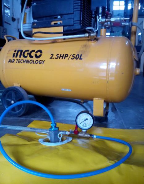
5 Volume 6, No. 2, February TESTING OF CONTINUOUS SLABS (CS): The experimental work on orthogonal slabs with openings parallel to long side and openings parallel to short side has not been reported so far in literature. The Slab 1.88m 1.28m is lifted up onto the testing platform and adjusted to have a continuous edges condition on all sides of the slab. Now the Slab with openings parallel to short side of size 0.288m 0.24m located at a distance 0.4m from the short edge and 0.22m from long edge, having the reinforcement details µ = 0.5, K = 4.0, K' x =0.67, K' y =1.33, I 2 = I 4 = 1.33,I 1 = I 3 =0.67 whose aspect ratio r = 1.5 and other relevant parameters were α= 0.16,β = 0.2, r 5 = 0.2, r 6 = 0.15, was loaded uniformly using pneumatic air pressure. The first crack was observed in dial gauge at a pressure of 0.2 Kg/cm 2 which was equivalent to a load of kn. The testing was continued and crack pattern was observed at a pressure of 0.37 Kg/cm 2 which was equivalent to 78.1kN and the failure pattern was marked with permanent marker (black) and was photographed and presented in Appendix B. The computer program for the above parameters gave the value of 2 /m ult =38.75 and. The theoretical predicted pattern and the pattern obtained after testing seems to be coinciding and hence W ult = = kn The predicted load was kN, whereas the load recorded was 78.1kN.These tests were planned to get the conformation of the failure pattern and ultimate load. The ratio of ultimate load to the predicted ultimate load is 1.. CONCLUSIONS 1. Design charts for two-way slabs with openings parallel to long side and short side for Continuous slabs with different size of openings at different locations for different aspect ratios 2. The charts developed can help any design engineer or architect to pick up once the choice of location of opening depending upon the plan or required strength criteria. 3. The charts can be used either for analysis or design of two-way slabs with different size of openings and different openings. 4. The charts can be used either for analysis or design of two-way slabs with different size of openings and at different locations. 5. A comparative study of ultimate strength of these cases is presented with the help of charts. (Appendix-B) 6. Few numerical examples are presented based on theorem of VI and VII of affine theorem of Johansen 1 for orthotropic slabs with two openings parallel to long side and short side. 7. The strength of slabs with openings parallel to short side is less when compared to other slabs with openings parallel to Long side 8. Casting and testing of one third scale models is done and observed that the strength obtained theoreticallyand experimentally is same 9. The details of testing and failure mechanisms of slab after test are photographed and given in Appendix-B. APPENDIX - A Charts Legend: Affine Coefficients Designers Choice Coefficients Reverse of Designers Choice Coefficients For Slabs with Openings Parallel to Long Side α=0.15,β=0.1,r 5 =0.2,r 6 =0.2 Chart-1 : α=0.15,β=0.1,r 5 =0.2,r 6 =0.2 α=0.15,β=0.1, r 5 =0.2, r 6 =0.2 Chart-2 : α=0.15,β=0.1,r 5 =0.2,r 6 =0.2
6 Volume 6, No. 2, February α=0.1,β=0.15, r 5 =0.2, r 6 =0.2 Aspect ratio,r α=0.1, β=0.1, r 5 =0., r 6 =0.2 Chart-3 : α=0.1,β=0.15,r 5 =0.2,r 6 =0.2 Chart-7 : α=0.1,β=0.1,r 5 =0.,r 6 =0.2 α=0.15,β=0.15, r 5 =0.2, r 6 =0.2 Aspect ratio,r α=0.1, β=0.15, r 5 =0., r 6 =0.2 Chart-4 : α=0.15,β=0.15,r 5 =0.2,r 6 =0.2 Chart-8 : α=0.1,β=0.15,r 5 =0.,r 6 =0.2 α=0.1, β=0.2, r 5 =0.2, r 6 =0.2 α=0.1, β=0.2,r 5 =0.,r 6 =0.2 Chart-5 : α=0.1,β=0.2,r 5 =0.2,r 6 =0.2 Chart-9 : α=0.1,β=0.2,r 5 =0.,r 6 =0.2 α=0.15, β=0.2, r 5 =0.2, r 6 =0.2 α=0.1, β=0.1, r 5 =0.2, r 6 =0. Chart-6 : α=0.15,β=0.2,r 5 =0.2,r 6 =0.2 Chart-10 : α=0.1,β=0.1,r 5 =0.2,r 6 =0.
7 Volume 6, No. 2, February α=0.15,β=0.1,r 5 =0.2,r 6 =0. Chart-11 : α=0.15,β=0.1,r 5 =0.2,r 6 =0. α=0.1,β=0.15,r 5 =0.2,r 6 =0. Chart-12 : α=0.1,β=0.15,r 5 =0.2,r 6 =0. α=0.15,β=0.15,r 5 =0.2,r 6 =0. Chart-13 : α=0.15,β=0.15,r 5 =0.2,r 6 =0. α=0.1,β=0.1,r 5 =0.,r 6 =0. Chart-14 : α=0.1,β=0.1,r 5 =0.,r 6 =0. For Slabs with Openings Parallel to Short Side α=0.1,β=0.15,r 5 =0.2,r 6 =0.2 Chart-15 : α=0.1,β=0.15,r 5 =0.2,r 6 =0.2 α=0.15,β=0.15,r 5 =0.2,r 6 =0.2 Chart-16 : α=0.15,β=0.15,r 5 =0.2,r 6 =0.2 α=0.2,β=0.15,r 5 =0.2,r 6 =0.2 Chart-17 : α=0.2,β=0.15,r 5 =0.2,r 6 =0.2 α=0.1,β=0.1,r 5 =0.2,r 6 =0.2 Chart-18 : α=0.1,β=0.1,r 5 =0.2,r 6 =0.2
8 Volume 6, No. 2, February α=0.15,β=0.1,r 5 =0.2,r 6 =0.2 Aspect ratio,r α=0.1,β=0.1,r 5 =0.,r 6 =0.2 Chart-19 : α=0.15,β=0.1,r 5 =0.2,r 6 =0.2 Chart-23 : α=0.1,β=0.1,r 5 =0.,r 6 =0.2 α=0.2,β=0.1,r 5 =0.2,r 6 =0.2 α=0.15,β=0.1,r 5 =0.,r 6 =0.2 Aspect ratio,r Chart- : α=0.2,β=0.1,r 5 =0.2,r 6 =0.2 Chart-24 : α=0.15,β=0.1,r 5 =0.,r 6 =0.2 α=0.1,β=0.15,r 5 =0.,r 6 =0.2 α=0.1,β=0.1,r 5 =0.2,r 6 =0. Chart-21 : α=0.1,β=0.15,r 5 =0.,r 6 =0.2 Chart- : α=0.1,β=0.1,r 5 =0.2,r 6 =0. α=0.15,β=0.15,r 5 =0.,r 6 =0.2 α=0.15,β=0.1,r 5 =0.2, r 6 =0. Chart-22: α=0.15,β=0.15,r 5 =0.,r 6 =0.2 Chart-26 : α=0.15,β=0.1,r 5 =0.2,r 6 =0.

9 Volume 6, No. 2, February α=0.1,β=0.1,r 5 =0.2,r 6 =0.2, K=4.0 µ=1,ls µ=1,ss Chart -27 : α=0.1,β=0.1,r 5 =0.2,r 6 =0.2 APPENDIX-B α=0.15,β=0.1,r 5 =0.2,r 6 =0.2, K=4.0 µ=1,ls µ=1,ss Chart -28 : α=0.15,β=0.1,r 5 =0.2,r 6 =0.2 α=0.15,β=0.1,r 5 =0.2,r 6 =0., K=4 PLATE 1: Box Setup made by Welding Mild Steel Channels and Angles and Bottom Part Covered with Wooden Plank µ=1,ls µ=1,ss Chart -29 : α=0.15,β=0.1,r 5 =0.2,r 6 =0. α=0.1,β=0.15,r 5 =0.,r 6 =0.2, K=4 µ=1,ls µ=1,ss Chart - : α=0.1,β=0.15,r 5 =0.,r 6 =0.2 PLATE 2: Inflatable Balloon which will Apply Pressure on Slab


10 Volume 6, No. 2, February PLATE 5: Failure Mechanism at a recorded load of 78.1 kn of CS slab with Long side openings PLATE 3 Inflatable Balloon which Will Apply Pressure on Slab is arranged inside the box setup PLATE 4 Slab Mounted on Setup and Fixed with Bolt and Nuts (As Per Edge Condition) List of Symbols CS A slab supported on all sides continuously,(restrained) D Overall depth of the slab DC Designer s Choice Coefficients I 1, I 2, I 3 Negative moment Coefficients in their and I 4, I 1 m ult, I 3 m ult I 2 m ult, I 4 m ult K ' xm ult K ' ym ult corresponding directions. Negative ultimate yield moment per unit length provided by top tension reinforcement bars placed parallel to x- axis. Negative ultimate yield moment per unit length provided by top tension reinforcement bars placed parallel to y- axis. Positive ultimate yield moment per unit length provided by bottom tension bars placed parallel to x-axis Positive ultimate yield moment per unit length provided by bottom tension bars placed parallel to y-axis L x, L y Slab dimensions in X and Y directions respectively RDC Reversal of Designer s Choice VWM W ult d f ck Coefficients Virtual Work Method. Ultimate uniformly distributed load per unit area of slab. Effective depth of slab in mm. Characteristic Compressive Strength of concrete, N/mm 2 f y Yield Strength of steel, N/mm 2 m ult Ultimate Yield moment per unit length of the slab r Aspect ratio of slab defined by L x /L y. r 5, r 6 Coefficients of Distances of openings from supports
11 Volume 6, No. 2, February UDL 2 m ult α, β K REFERENCES uniformly distributed load Often called as strength of slab at ultimate stage Coefficients of openings in the slab Sum of orthogonal moment coefficients in x and y directions i.e K ' x+ K ' y+i 1 (or I 3 )+ I 2 (or I 4 ) µ Coefficient of orthotropy= [K ' x+i 1 (or I 3 )]/[ K ' y + I 2 (or I 4 )] Negative yield line Positive yield line Continuous edge [1] K.W. Johansen, Yield-Line Theory (Cement and Concrete Association, London, 1962), p. 181 [2] K.W. Johansen, Yield-Line Formulae for Slabs (Cement and Concrete Association, London, 1972) [3] ACI 421.3R-15, Guide to design of reinforced twoway slab systems. American Concrete Institute, p. 11 [4] British Standards Institution, BS : The structural use of concrete part 1, Code of practice for design and construction. BSI (1997) [5] IS 6:00, Indian standard plain and reinforced concrete-code of practice, BIS New Delhi, India [6] R. Park, W.L. Gamble, Reinforced Concrete Slabs (Wiley, New York, 00) [7] S. Islam, R. Park, Yield line analysis of two-way reinforced concrete slabs with openings. J. Struct. Eng. 49(6), (1971) [8] A. Zaslavasky, Yield line analysis of rectangular slabs with central opening. Proc. ACI 64, (1967) [9] K. Rambabu, Yield line analysis of orthotropic rectangular two- way slab supported on four sides with openings. Ph.D. Thesis in Struct. Engg., Vol. 2, Andhra University, India (01) [10] K. Rambabu, H.B. Goli, Y.D. Shaik, Application of affine theorem to orthotropic rectangular reinforced concrete slab with unequal corner opening. J. Struct. Eng. 36(3), (09). (India, 13) [11] Sudhakar,K.J., and andgoli, H.B., Detailing of regular and irregular shape of RC slabs by yield line method, National Seminar on Detailing of RC and Steel Structures, Madras, rd Dec [12] M. Ravindra, K. Rambabu, H.B. Goli, Application of the affine theorem to an orthotropic rectangular reinforced concrete slab continuous over two adjacent sides and simply supported on other two sides having a short side opening. J. Struct. Eng. 41(2), (09). (India, 14) [13] Manasa, K. Rambabu and K. DurgaRani, Application of modified affine theorem to orthotropic rectangular reinforced concrete slab with interior corner opening parallel to shorter side, Journal of Structural Engineer, SERC,Vol. No., Issue No.4. pp [14] 14. C.E. Reynolds, J.C. Steedman, Reinforced Concrete Designers Hand Book (Taylor and Francis, London, 08). (pp , 137 1)
A Study on Behaviour of Symmetrical I-Shaped Column Using Interaction Diagram
 A Study on Behaviour of Symmetrical I-Shaped Column Using Interaction Diagram Sudharma.V.S.Acharya 1, R.M. Subrahmanya 2, B.G. Naresh Kumar 3, Shanmukha Shetty 4, Smitha 5 P.G. Student, Department of Civil
Civil Engineering Design (1) Analysis and Design of Slabs 2006/7
 Analysis and Design of Slabs 2006/7") Civil Engineering Design (1) Analysis and Design of Slabs 006/7 Dr. Colin Caprani, Chartered Engineer 1 Contents 1. Elastic Methods... 3 1.1 Introduction... 3 1. Grillage Analysis... 4 1.3 Finite Element
Civil Engineering Design (1) Analysis and Design of Slabs 006/7 Dr. Colin Caprani, Chartered Engineer 1 Contents 1. Elastic Methods... 3 1.1 Introduction... 3 1. Grillage Analysis... 4 1.3 Finite Element
Associate Professor. Tel:
 DEPARTMENT OF CIVIL ENGINEERING IIT DELHI Dr. Suresh Bhalla Associate Professor Tel: 2659-1040 Email: Sbhalla@civil.iitd.ac.in FOUNDATIONS Geotechnical Engineer Structural Engineer Location and depth criteria
PASSIVE COOLING DESIGN FEATURE FOR ENERGY EFFICIENT IN PERI AUDITORIUM
 PASSIVE COOLING DESIGN FEATURE FOR ENERGY EFFICIENT IN PERI AUDITORIUM M. Hari Sathish Kumar 1, K. Pavithra 2, D.Prakash 3, E.Sivasaranya 4, 1Assistant Professor, Department of Civil Engineering, PERI
DESIGN OF STAIRCASE. Dr. Izni Syahrizal bin Ibrahim. Faculty of Civil Engineering Universiti Teknologi Malaysia
 DESIGN OF STAIRCASE Dr. Izni Syahrizal bin Ibrahim Faculty of Civil Engineering Universiti Teknologi Malaysia Email: iznisyahrizal@utm.my Introduction T N T G N G R h Flight Span, L Landing T = Thread
Module 6. Shear, Bond, Anchorage, Development Length and Torsion. Version 2 CE IIT, Kharagpur
 Module 6 Shear, Bond, Anchorage, Development Length and Torsion Lesson 15 Bond, Anchorage, Development Length and Splicing Instruction Objectives: At the end of this lesson, the student should be able
Annex - R C Design Formulae and Data
 The design formulae and data provided in this Annex are for education, training and assessment purposes only. They are based on the Hong Kong Code of Practice for Structural Use of Concrete 2013 (HKCP-2013).
Prediction of Reliability Index and Probability of Failure for Reinforced Concrete Beam Subjected To Flexure
 Prediction of Reliability Index and Probability of Failure for Reinforced Concrete Beam Subjected To Flexure Salma Taj 1, Karthik B.M. 1, Mamatha N.R. 1, Rakesh J. 1, Goutham D.R. 2 1 UG Students, Dept.
Module 14. Tension Members. Version 2 CE IIT, Kharagpur
 Module 14 Tension Members Lesson 37 Numerical Problems Instructional Objectives: At the end of this lesson, the student should be able to: select the category of the problem if it is a liquid retaining
 UNIT III DEFLECTION OF BEAMS 1. What are the methods for finding out the slope and deflection at a section? The important methods used for finding out the slope and deflection at a section in a loaded
CAPACITY DESIGN FOR TALL BUILDINGS WITH MIXED SYSTEM
 13 th World Conference on Earthquake Engineering Vancouver, B.C., Canada August 1-6, 24 Paper No. 2367 CAPACITY DESIGN FOR TALL BUILDINGS WITH MIXED SYSTEM M.UMA MAHESHWARI 1 and A.R.SANTHAKUMAR 2 SUMMARY
Lecture 7 Two-Way Slabs
 Lecture 7 Two-Way Slabs Two-way slabs have tension reinforcing spanning in BOTH directions, and may take the general form of one of the following: Types of Two-Way Slab Systems Lecture 7 Page 1 of 13 The
CE5510 Advanced Structural Concrete Design - Design & Detailing of Openings in RC Flexural Members-
 CE5510 Advanced Structural Concrete Design - Design & Detailing Openings in RC Flexural Members- Assoc Pr Tan Kiang Hwee Department Civil Engineering National In this lecture DEPARTMENT OF CIVIL ENGINEERING
REINFORCED CONCRETE STRUCTURES DESIGN AND DRAWING (ACE009)
") LECTURE NOTES ON REINFORCED CONCRETE STRUCTURES DESIGN AND DRAWING (ACE009) III B. Tech I semester (Regulation- R16) Mr. Gude Ramakrishna Associate Professor DEPARTMENT OF CIVIL ENGINEERING INSTITUTE OF
LECTURE NOTES ON REINFORCED CONCRETE STRUCTURES DESIGN AND DRAWING (ACE009) III B. Tech I semester (Regulation- R16) Mr. Gude Ramakrishna Associate Professor DEPARTMENT OF CIVIL ENGINEERING INSTITUTE OF
DESIGN AND DETAILING OF COUNTERFORT RETAINING WALL
 DESIGN AND DETAILING OF COUNTERFORT RETAINING WALL When the height of the retaining wall exceeds about 6 m, the thickness of the stem and heel slab works out to be sufficiently large and the design becomes
Civil Engineering Design (1) Design of Reinforced Concrete Columns 2006/7
 Design of Reinforced Concrete Columns 2006/7") Civil Engineering Design (1) Design of Reinforced Concrete Columns 2006/7 Dr. Colin Caprani, Chartered Engineer 1 Contents 1. Introduction... 3 1.1 Background... 3 1.2 Failure Modes... 5 1.3 Design Aspects...
Civil Engineering Design (1) Design of Reinforced Concrete Columns 2006/7 Dr. Colin Caprani, Chartered Engineer 1 Contents 1. Introduction... 3 1.1 Background... 3 1.2 Failure Modes... 5 1.3 Design Aspects...
BE Semester- I ( ) Question Bank (MECHANICS OF SOLIDS)
 Question Bank (MECHANICS OF SOLIDS)") BE Semester- I ( ) Question Bank (MECHANICS OF SOLIDS) All questions carry equal marks(10 marks) Q.1 (a) Write the SI units of following quantities and also mention whether it is scalar or vector: (i)
BE Semester- I ( ) Question Bank (MECHANICS OF SOLIDS) All questions carry equal marks(10 marks) Q.1 (a) Write the SI units of following quantities and also mention whether it is scalar or vector: (i)
K Design Graphs and Charts for Raft Foundations Spanning Local Depressions
 K Design Graphs and Charts for Raft Foundations Spanning Local Depressions The reader is advised to read the text in Chapter 13 before using these charts. The charts and figures are repeated here for quick
Job No. Sheet No. Rev. CONSULTING Engineering Calculation Sheet. Member Design - RC Two Way Spanning Slab XX
 CONSULTING Engineering Calculation Sheet E N G I N E E R S Consulting Engineers jxxx 1 Material Properties Characteristic strength of concrete, f cu ( 60N/mm 2 ; HSC N/A) 35 N/mm 2 OK Yield strength of
CHAPTER 4. Stresses in Beams
 CHAPTER 4 Stresses in Beams Problem 1. A rolled steel joint (RSJ) of -section has top and bottom flanges 150 mm 5 mm and web of size 00 mm 1 mm. t is used as a simply supported beam over a span of 4 m
Module 12. Yield Line Analysis for Slabs. Version 2 CE IIT, Kharagpur
 Module 12 Yield Line Analysis for Slabs Lesson 30 Basic Principles, Theory and One-way Slabs Instructional Objectives: At the end of this lesson, the student should be able to: state the limitations of
Example 2.2 [Ribbed slab design]
![Example 2.2 [Ribbed slab design]](/thumbs/78/77625473.jpg "Example 2.2 [Ribbed slab design]") Example 2.2 [Ribbed slab design] A typical floor system of a lecture hall is to be designed as a ribbed slab. The joists which are spaced at 400mm are supported by girders. The overall depth of the slab
Example 2.2 [Ribbed slab design] A typical floor system of a lecture hall is to be designed as a ribbed slab. The joists which are spaced at 400mm are supported by girders. The overall depth of the slab
Delhi Noida Bhopal Hyderabad Jaipur Lucknow Indore Pune Bhubaneswar Kolkata Patna Web: Ph:
 Serial : IG1_CE_G_Concrete Structures_100818 Delhi Noida Bhopal Hyderabad Jaipur Lucknow Indore Pune Bhubaneswar Kolkata Patna Web: E-mail: info@madeeasy.in Ph: 011-451461 CLASS TEST 018-19 CIVIL ENGINEERING
Design of Beams (Unit - 8)
") Design of Beams (Unit - 8) Contents Introduction Beam types Lateral stability of beams Factors affecting lateral stability Behaviour of simple and built - up beams in bending (Without vertical stiffeners)
Design of Beams (Unit - 8) Contents Introduction Beam types Lateral stability of beams Factors affecting lateral stability Behaviour of simple and built - up beams in bending (Without vertical stiffeners)
QUESTION BANK SEMESTER: III SUBJECT NAME: MECHANICS OF SOLIDS
 QUESTION BANK SEMESTER: III SUBJECT NAME: MECHANICS OF SOLIDS UNIT 1- STRESS AND STRAIN PART A (2 Marks) 1. Define longitudinal strain and lateral strain. 2. State Hooke s law. 3. Define modular ratio,
Roadway Grade = m, amsl HWM = Roadway grade dictates elevation of superstructure and not minimum free board requirement.
 Example on Design of Slab Bridge Design Data and Specifications Chapter 5 SUPERSTRUCTURES Superstructure consists of 10m slab, 36m box girder and 10m T-girder all simply supported. Only the design of Slab
Module 13. Working Stress Method. Version 2 CE IIT, Kharagpur
 Module 13 Working Stress Method Lesson 35 Numerical Problems Instructional Objectives: At the end of this lesson, the student should be able to: employ the equations established for the analysis and design
QUESTION BANK DEPARTMENT: CIVIL SEMESTER: III SUBJECT CODE: CE2201 SUBJECT NAME: MECHANICS OF SOLIDS UNIT 1- STRESS AND STRAIN PART A
 DEPARTMENT: CIVIL SUBJECT CODE: CE2201 QUESTION BANK SEMESTER: III SUBJECT NAME: MECHANICS OF SOLIDS UNIT 1- STRESS AND STRAIN PART A (2 Marks) 1. Define longitudinal strain and lateral strain. 2. State
DESIGN OF STEEL GRILLAGE FOUNDATION FOR AN AUDITORIUM
 DESIGN OF STEEL GRILLAGE FOUNDATION FOR AN AUDITORIUM Dr.R.Rajesh guna 1, T.Dilipkumar 2, J.Kaleel 3, M.Vidhyalakshmi 4, 1Assistant Professor, Department of Civil Engineering, PERI Institute of Technology,
Bending and Shear in Beams
 Bending and Shear in Beams Lecture 3 5 th October 017 Contents Lecture 3 What reinforcement is needed to resist M Ed? Bending/ Flexure Section analysis, singly and doubly reinforced Tension reinforcement,
TABLE OF CONTANINET 1. Design criteria. 2. Lateral loads. 3. 3D finite element model (SAP2000, Ver.16). 4. Design of vertical elements (CSI, Ver.9).
. 4. Design of vertical elements (CSI, Ver.9).") TABLE OF CONTANINET 1. Design criteria. 2. Lateral loads. 2-1. Wind loads calculation 2-2. Seismic loads 3. 3D finite element model (SAP2000, Ver.16). 4. Design of vertical elements (CSI, Ver.9). 4-1.
TABLE OF CONTANINET 1. Design criteria. 2. Lateral loads. 2-1. Wind loads calculation 2-2. Seismic loads 3. 3D finite element model (SAP2000, Ver.16). 4. Design of vertical elements (CSI, Ver.9). 4-1.
CHAPTER 4. Design of R C Beams
 CHAPTER 4 Design of R C Beams Learning Objectives Identify the data, formulae and procedures for design of R C beams Design simply-supported and continuous R C beams by integrating the following processes
Downloaded from Downloaded from / 1
 PURWANCHAL UNIVERSITY III SEMESTER FINAL EXAMINATION-2002 LEVEL : B. E. (Civil) SUBJECT: BEG256CI, Strength of Material Full Marks: 80 TIME: 03:00 hrs Pass marks: 32 Candidates are required to give their
Name :. Roll No. :... Invigilator s Signature :.. CS/B.TECH (CE-NEW)/SEM-3/CE-301/ SOLID MECHANICS
/SEM-3/CE-301/ SOLID MECHANICS") Name :. Roll No. :..... Invigilator s Signature :.. 2011 SOLID MECHANICS Time Allotted : 3 Hours Full Marks : 70 The figures in the margin indicate full marks. Candidates are required to give their answers
Name :. Roll No. :..... Invigilator s Signature :.. 2011 SOLID MECHANICS Time Allotted : 3 Hours Full Marks : 70 The figures in the margin indicate full marks. Candidates are required to give their answers
9.5 Compression Members
 9.5 Compression Members This section covers the following topics. Introduction Analysis Development of Interaction Diagram Effect of Prestressing Force 9.5.1 Introduction Prestressing is meaningful when
3.5 Analysis of Members under Flexure (Part IV)
") 3.5 Analysis o Members under Flexure (Part IV) This section covers the ollowing topics. Analysis o a Flanged Section 3.5.1 Analysis o a Flanged Section Introduction A beam can have langes or lexural eiciency.
3.5 Analysis o Members under Flexure (Part IV) This section covers the ollowing topics. Analysis o a Flanged Section 3.5.1 Analysis o a Flanged Section Introduction A beam can have langes or lexural eiciency.
CIVIL DEPARTMENT MECHANICS OF STRUCTURES- ASSIGNMENT NO 1. Brach: CE YEAR:
 MECHANICS OF STRUCTURES- ASSIGNMENT NO 1 SEMESTER: V 1) Find the least moment of Inertia about the centroidal axes X-X and Y-Y of an unequal angle section 125 mm 75 mm 10 mm as shown in figure 2) Determine
Case Study in Reinforced Concrete adapted from Simplified Design of Concrete Structures, James Ambrose, 7 th ed.
 ARCH 631 Note Set 11 S017abn Case Study in Reinforced Concrete adapted from Simplified Design of Concrete Structures, James Ambrose, 7 th ed. Building description The building is a three-story office building
SPECIFIC VERIFICATION Chapter 5
 As = 736624/(0.5*413.69) = 3562 mm 2 (ADAPT 3569 mm 2, B29, C6) Data Block 27 - Compressive Stresses The initial compressive strength, f ci, is the strength entered in the Material/Concrete input screen.
STRUCTURAL ANALYSIS CHAPTER 2. Introduction
 CHAPTER 2 STRUCTURAL ANALYSIS Introduction The primary purpose of structural analysis is to establish the distribution of internal forces and moments over the whole part of a structure and to identify
Job No. Sheet No. Rev. CONSULTING Engineering Calculation Sheet. Member Design - Steel Composite Beam XX 22/09/2016
 CONSULTING Engineering Calculation Sheet jxxx 1 Member Design - Steel Composite Beam XX Introduction Chd. 1 Grade 50 more common than Grade 43 because composite beam stiffness often 3 to 4 times non composite
PERIYAR CENTENARY POLYTECHNIC COLLEGE PERIYAR NAGAR - VALLAM THANJAVUR. DEPARTMENT OF MECHANICAL ENGINEERING QUESTION BANK
 PERIYAR CENTENARY POLYTECHNIC COLLEGE PERIYAR NAGAR - VALLAM - 613 403 - THANJAVUR. DEPARTMENT OF MECHANICAL ENGINEERING QUESTION BANK Sub : Strength of Materials Year / Sem: II / III Sub Code : MEB 310
 Balcony balustrades using the SG12 laminated glass system: PAGE 1 (SG12FF010717) Structural Calculations for SG12 System balustrades using 21.5mm laminated toughened glass without the need for a handrail
Pre-stressed concrete = Pre-compression concrete Pre-compression stresses is applied at the place when tensile stress occur Concrete weak in tension
 Pre-stressed concrete = Pre-compression concrete Pre-compression stresses is applied at the place when tensile stress occur Concrete weak in tension but strong in compression Steel tendon is first stressed
8 Deflectionmax. = 5WL 3 384EI
 8 max. = 5WL 3 384EI 1 salesinfo@mechanicalsupport.co.nz PO Box 204336 Highbrook Auckland www.mechanicalsupport.co.nz 2 Engineering Data - s and Columns Structural Data 1. Properties properties have been
Tower Cranes & Foundations The Interface & CIRIA C654 Stuart Marchand C.Eng. FICE FIStructE Director Wentworth House Partnership
 Tower Cranes & Foundations The Interface & CIRIA C654 Stuart Marchand C.Eng. FICE FIStructE Director Wentworth House Partnership EXAMPLES OF TOWER CRANE FOUNDATION TYPES Rail mounted Pad Base Piled Base
Entrance exam Master Course
 - 1 - Guidelines for completion of test: On each page, fill in your name and your application code Each question has four answers while only one answer is correct. o Marked correct answer means 4 points
Structural Calculations for Juliet balconies using BALCONY 2 System (Aerofoil) handrail. Our ref: JULB2NB Date of issue: March 2017
 handrail. Our ref: JULB2NB Date of issue: March 2017") Juliet balconies using BALCONY 2 System (Aerofoil) handrail PAGE 1 (ref: JULB2NB280317) Structural Calculations for Juliet balconies using BALCONY 2 System (Aerofoil) handrail Our ref: JULB2NB280317 Date
Juliet balconies using BALCONY 2 System (Aerofoil) handrail PAGE 1 (ref: JULB2NB280317) Structural Calculations for Juliet balconies using BALCONY 2 System (Aerofoil) handrail Our ref: JULB2NB280317 Date
Assignment 1 - actions
 Assignment 1 - actions b = 1,5 m a = 1 q kn/m 2 Determine action on the beam for verification of the ultimate limit state. Axial distance of the beams is 1 to 2 m, cross section dimensions 0,45 0,20 m
UNIVERSITY OF BOLTON SCHOOL OF ENGINEERING. BEng (HONS) CIVIL ENGINEERING SEMESTER 1 EXAMINATION 2016/2017 MATHEMATICS & STRUCTURAL ANALYSIS
 CIVIL ENGINEERING SEMESTER 1 EXAMINATION 2016/2017 MATHEMATICS & STRUCTURAL ANALYSIS") TW21 UNIVERSITY OF BOLTON SCHOOL OF ENGINEERING BEng (HONS) CIVIL ENGINEERING SEMESTER 1 EXAMINATION 2016/2017 MATHEMATICS & STRUCTURAL ANALYSIS MODULE NO: CIE4011 Date: Wednesday 11 th January 2017 Time:
TW21 UNIVERSITY OF BOLTON SCHOOL OF ENGINEERING BEng (HONS) CIVIL ENGINEERING SEMESTER 1 EXAMINATION 2016/2017 MATHEMATICS & STRUCTURAL ANALYSIS MODULE NO: CIE4011 Date: Wednesday 11 th January 2017 Time:
Fire Analysis of Reinforced Concrete Beams with 2-D Plane Stress Concrete Model
 Research Journal of Applied Sciences, Engineering and Technology 5(2): 398-44, 213 ISSN: 24-7459; E-ISSN: 24-7467 Maxwell Scientific Organization, 213 Submitted: April 29, 212 Accepted: May 23, 212 Published:
REGRESSION MODELING FOR STRENGTH AND TOUGHNESS EVALUATION OF HYBRID FIBRE REINFORCED CONCRETE
 REGRESSION MODELING FOR STRENGTH AND TOUGHNESS EVALUATION OF HYBRID FIBRE REINFORCED CONCRETE S. Eswari 1, P. N. Raghunath and S. Kothandaraman 1 1 Department of Civil Engineering, Pondicherry Engineering
PUNCHING SHEAR CALCULATIONS 1 ACI 318; ADAPT-PT
 Structural Concrete Software System TN191_PT7_punching_shear_aci_4 011505 PUNCHING SHEAR CALCULATIONS 1 ACI 318; ADAPT-PT 1. OVERVIEW Punching shear calculation applies to column-supported slabs, classified
Design of AAC wall panel according to EN 12602
 Design of wall panel according to EN 160 Example 3: Wall panel with wind load 1.1 Issue Design of a wall panel at an industrial building Materials with a compressive strength 3,5, density class 500, welded
CHAPTER 5 Statically Determinate Plane Trusses
 CHAPTER 5 Statically Determinate Plane Trusses TYPES OF ROOF TRUSS TYPES OF ROOF TRUSS ROOF TRUSS SETUP ROOF TRUSS SETUP OBJECTIVES To determine the STABILITY and DETERMINACY of plane trusses To analyse
FINITE ELEMENT ANALYSIS OF TAPERED COMPOSITE PLATE GIRDER WITH A NON-LINEAR VARYING WEB DEPTH
 Journal of Engineering Science and Technology Vol. 12, No. 11 (2017) 2839-2854 School of Engineering, Taylor s University FINITE ELEMENT ANALYSIS OF TAPERED COMPOSITE PLATE GIRDER WITH A NON-LINEAR VARYING
CHAPTER 5 Statically Determinate Plane Trusses TYPES OF ROOF TRUSS
 CHAPTER 5 Statically Determinate Plane Trusses TYPES OF ROOF TRUSS 1 TYPES OF ROOF TRUSS ROOF TRUSS SETUP 2 ROOF TRUSS SETUP OBJECTIVES To determine the STABILITY and DETERMINACY of plane trusses To analyse
CIV100 Mechanics. Module 5: Internal Forces and Design. by: Jinyue Zhang. By the end of this Module you should be able to:
 CIV100 Mechanics Module 5: Internal Forces and Design by: Jinyue Zhang Module Objective By the end of this Module you should be able to: Find internal forces of any structural members Understand how Shear
Chapter (6) Geometric Design of Shallow Foundations
 Geometric Design of Shallow Foundations") Chapter (6) Geometric Design of Shallow Foundations Introduction As we stated in Chapter 3, foundations are considered to be shallow if if [D (3 4)B]. Shallow foundations have several advantages: minimum
Chapter (6) Geometric Design of Shallow Foundations Introduction As we stated in Chapter 3, foundations are considered to be shallow if if [D (3 4)B]. Shallow foundations have several advantages: minimum
Design of a Multi-Storied RC Building
 Design of a Multi-Storied RC Building 16 14 14 3 C 1 B 1 C 2 B 2 C 3 B 3 C 4 13 B 15 (S 1 ) B 16 (S 2 ) B 17 (S 3 ) B 18 7 B 4 B 5 B 6 B 7 C 5 C 6 C 7 C 8 C 9 7 B 20 B 22 14 B 19 (S 4 ) C 10 C 11 B 23
STRENGTH OF MATERIALS-I. Unit-1. Simple stresses and strains
 STRENGTH OF MATERIALS-I Unit-1 Simple stresses and strains 1. What is the Principle of surveying 2. Define Magnetic, True & Arbitrary Meridians. 3. Mention different types of chains 4. Differentiate between
Two Way Beam Supported Slab
 Two Way Beam Supported Slab Part 2 The following example was done by Mr. Naim Hassan, 3 rd Year 2 nd Semester Student of CE Dept., AUST 16 The following Example was done by Md. Mahmudun Nobe, ID -.01.03.078,
Lecture-08 Gravity Load Analysis of RC Structures
 Lecture-08 Gravity Load Analysis of RC Structures By: Prof Dr. Qaisar Ali Civil Engineering Department UET Peshawar www.drqaisarali.com 1 Contents Analysis Approaches Point of Inflection Method Equivalent
Purpose of this Guide: To thoroughly prepare students for the exact types of problems that will be on Exam 3.
 ES230 STRENGTH OF MTERILS Exam 3 Study Guide Exam 3: Wednesday, March 8 th in-class Updated 3/3/17 Purpose of this Guide: To thoroughly prepare students for the exact types of problems that will be on
Strength of Materials (15CV 32)
") Strength of Materials (15CV 32) Module 1 : Simple Stresses and Strains Dr. H. Ananthan, Professor, VVIET,MYSURU 8/21/2017 Introduction, Definition and concept and of stress and strain. Hooke s law, Stress-Strain
Strength of Materials (15CV 32) Module 1 : Simple Stresses and Strains Dr. H. Ananthan, Professor, VVIET,MYSURU 8/21/2017 Introduction, Definition and concept and of stress and strain. Hooke s law, Stress-Strain
Mechanics of Solids. Mechanics Of Solids. Suraj kr. Ray Department of Civil Engineering
 Mechanics Of Solids Suraj kr. Ray (surajjj2445@gmail.com) Department of Civil Engineering 1 Mechanics of Solids is a branch of applied mechanics that deals with the behaviour of solid bodies subjected
UNIT-I STRESS, STRAIN. 1. A Member A B C D is subjected to loading as shown in fig determine the total elongation. Take E= 2 x10 5 N/mm 2
 UNIT-I STRESS, STRAIN 1. A Member A B C D is subjected to loading as shown in fig determine the total elongation. Take E= 2 x10 5 N/mm 2 Young s modulus E= 2 x10 5 N/mm 2 Area1=900mm 2 Area2=400mm 2 Area3=625mm
UNIT II SHALLOW FOUNDATION
 Introduction UNIT II SHALLOW FOUNDATION A foundation is a integral part of the structure which transfer the load of the superstructure to the soil. A foundation is that member which provides support for
VTU EDUSAT PROGRAMME Lecture Notes on Design of Columns
 VTU EDUSAT PROGRAMME 17 2012 Lecture Notes on Design of Columns DESIGN OF RCC STRUCTURAL ELEMENTS - 10CV52 (PART B, UNIT 6) Dr. M. C. Nataraja Professor, Civil Engineering Department, Sri Jayachamarajendra
Job No. Sheet No. Rev. CONSULTING Engineering Calculation Sheet. Member Design - Reinforced Concrete Staircase BS8110
 CONSULTING Engineering Calculation Sheet E N G I N E E R S Consulting Engineers jxxx 1 Material Properties Characteristic strength of concrete, f cu ( 60N/mm 2 ; HSC N/A) 30 N/mm 2 OK Yield strength of
NONLINEAR CHARACTERISTICS OF THE PILE-SOIL SYSTEM UNDER VERTICAL VIBRATION
 IGC 2009, Guntur, INDIA NONLINEAR CHARACTERISTICS OF THE PILE-SOIL SYSTEM UNDER VERTICAL VIBRATION B. Manna Lecturer, Civil Engineering Department, National Institute of Technology, Rourkela 769008, India.
Example 4: Design of a Rigid Column Bracket (Bolted)
") Worked Example 4: Design of a Rigid Column Bracket (Bolted) Example 4: Design of a Rigid Column Bracket (Bolted) Page : 1 Example 4: Design of a Rigid Column Bracket (Bolted) Determine the size of the
Worked Example 4: Design of a Rigid Column Bracket (Bolted) Example 4: Design of a Rigid Column Bracket (Bolted) Page : 1 Example 4: Design of a Rigid Column Bracket (Bolted) Determine the size of the
Modeling of Interfacial Debonding Induced by IC Crack for Concrete Beam-bonded with CFRP
 Proceedings of the World Congress on Engineering 21 Vol II WCE 21, June 2 - July 1, 21, London, U.K. Modeling of Interfacial Debonding Induced by IC Crack for Concrete Beam-bonded with CFRP Lihua Huang,
Keywords: Reliability; Monte Carlo method; Simulation; R.C.C Column Design
 Monte Carlo Simulation Technique For Reliability Assessment Of R.C.C. Columns Sukanti Rout*, Santosh Kumar Sahoo**, Bidyadhar Basa*** *(Department Civil Engineering, SOA University, Bhubaneswar-30) **
EFFECT OF SHEAR REINFORCEMENT ON FAILURE MODE OF RC BRIDGE PIERS SUBJECTED TO STRONG EARTHQUAKE MOTIONS
 EFFECT OF SHEAR REINFORCEMENT ON FAILURE MODE OF RC BRIDGE PIERS SUBJECTED TO STRONG EARTHQUAKE MOTIONS Atsuhiko MACHIDA And Khairy H ABDELKAREEM SUMMARY Nonlinear D FEM was utilized to carry out inelastic
Serviceability Deflection calculation
 Chp-6:Lecture Goals Serviceability Deflection calculation Deflection example Structural Design Profession is concerned with: Limit States Philosophy: Strength Limit State (safety-fracture, fatigue, overturning
Prediction of static response of Laced Steel-Concrete Composite beam using effective moment of inertia approach
 Prediction of static response of Laced Steel-Concrete Composite beam using effective moment of inertia approach Thirumalaiselvi A 1, 2, Anandavalli N 1,2, Rajasankar J 1,2, Nagesh R. Iyer 2 1 Academy of
Artificial Neural Network Based Approach for Design of RCC Columns
 Artificial Neural Network Based Approach for Design of RCC Columns Dr T illai, ember I Karthekeyan, Non-member Recent developments in artificial neural network have opened up new possibilities in the field
PROPOSED SATSANG HALL TECHNICAL REPORT
 PROPOSED SATSANG HALL - VERTICAL STRIP V1 1 ------------------------------------------------------------------------------ ADAPT CORPORATION STRUCTURAL CONCRETE SOFTWARE SYSTEM 1733 Woodside Road, Suite
Address for Correspondence
 Research Article EXPERIMENT STUDY OF DYNAMIC RESPONSE OF SOFT STOREY BUILDING MODEL C. S. Sanghvi 1, H S Patil 2 and B J Shah 3 Address for Correspondence 1 Associate Professor, Applied Mechanics Department,
Job No. Sheet No. Rev. CONSULTING Engineering Calculation Sheet. Member Design - Reinforced Concrete Staircase BS8110
 CONSULTING Engineering Calculation Sheet E N G I N E E R S Consulting Engineers jxxx 1 Material Properties Characteristic strength of concrete, f cu ( 60N/mm 2 ; HSC N/A) 25 N/mm 2 OK Yield strength of
Chapter. Materials. 1.1 Notations Used in This Chapter
 Chapter 1 Materials 1.1 Notations Used in This Chapter A Area of concrete cross-section C s Constant depending on the type of curing C t Creep coefficient (C t = ε sp /ε i ) C u Ultimate creep coefficient
SRI CHANDRASEKHARENDRA SARASWATHI VISWA MAHAVIDHYALAYA
 SRI CHANDRASEKHARENDRA SARASWATHI VISWA MAHAVIDHYALAYA (Declared as Deemed-to-be University under Section 3 of the UGC Act, 1956, Vide notification No.F.9.9/92-U-3 dated 26 th May 1993 of the Govt. of
CONSULTING Engineering Calculation Sheet. Job Title Member Design - Reinforced Concrete Column BS8110
 E N G I N E E R S Consulting Engineers jxxx 1 Job Title Member Design - Reinforced Concrete Column Effects From Structural Analysis Axial force, N (tension-ve and comp +ve) (ensure >= 0) 8000kN OK Major
Module 5. Flanged Beams Theory and Numerical Problems. Version 2 CE IIT, Kharagpur
 Module 5 Flanged Beams Theory and Numerical Problems Lesson 10 Flanged Beams Theory Instructional Objectives: At the end of this lesson, the student should be able to: identify the regions where the beam
Figure 1: Representative strip. = = 3.70 m. min. per unit length of the selected strip: Own weight of slab = = 0.
 Example (8.1): Using the ACI Code approximate structural analysis, design for a warehouse, a continuous one-way solid slab supported on beams 4.0 m apart as shown in Figure 1. Assume that the beam webs
1. ARRANGEMENT. a. Frame A1-P3. L 1 = 20 m H = 5.23 m L 2 = 20 m H 1 = 8.29 m L 3 = 20 m H 2 = 8.29 m H 3 = 8.39 m. b. Frame P3-P6
 Page 3 Page 4 Substructure Design. ARRANGEMENT a. Frame A-P3 L = 20 m H = 5.23 m L 2 = 20 m H = 8.29 m L 3 = 20 m H 2 = 8.29 m H 3 = 8.39 m b. Frame P3-P6 L = 25 m H 3 = 8.39 m L 2 = 3 m H 4 = 8.5 m L
Plastic design of continuous beams
 Budapest University of Technology and Economics Department of Mechanics, Materials and Structures English courses Reinforced Concrete Structures Code: BMEEPSTK601 Lecture no. 4: Plastic design of continuous
INFLUENCE OF FLANGE STIFFNESS ON DUCTILITY BEHAVIOUR OF PLATE GIRDER
 International Journal of Civil Structural 6 Environmental And Infrastructure Engineering Research Vol.1, Issue.1 (2011) 1-15 TJPRC Pvt. Ltd.,. INFLUENCE OF FLANGE STIFFNESS ON DUCTILITY BEHAVIOUR OF PLATE
Design of Steel Structures Prof. S.R.Satish Kumar and Prof. A.R.Santha Kumar
 5.10 Examples 5.10.1 Analysis of effective section under compression To illustrate the evaluation of reduced section properties of a section under axial compression. Section: 00 x 80 x 5 x 4.0 mm Using
3.2 Reinforced Concrete Slabs Slabs are divided into suspended slabs. Suspended slabs may be divided into two groups:
 Sabah Shawkat Cabinet of Structural Engineering 017 3. Reinforced Concrete Slabs Slabs are divided into suspended slabs. Suspended slabs may be divided into two groups: (1) slabs supported on edges of
STRUCTURAL CALCULATIONS
 STRUCTURAL CALCULATIONS FOR SG10 SYSTEM BALUSTRADES USING 21.5mm LAMINATED TOUGHENED GLASS without the need for a handrail BY BALCONY SYSTEMS LIMITED Unit 6 Systems House Eastbourne Road Blindly Heath
EDEM DISCRETIZATION (Phase II) Normal Direction Structure Idealization Tangential Direction Pore spring Contact spring SPRING TYPES Inner edge Inner d
 Normal Direction Structure Idealization Tangential Direction Pore spring Contact spring SPRING TYPES Inner edge Inner d") Institute of Industrial Science, University of Tokyo Bulletin of ERS, No. 48 (5) A TWO-PHASE SIMPLIFIED COLLAPSE ANALYSIS OF RC BUILDINGS PHASE : SPRING NETWORK PHASE Shanthanu RAJASEKHARAN, Muneyoshi
Institute of Industrial Science, University of Tokyo Bulletin of ERS, No. 48 (5) A TWO-PHASE SIMPLIFIED COLLAPSE ANALYSIS OF RC BUILDINGS PHASE : SPRING NETWORK PHASE Shanthanu RAJASEKHARAN, Muneyoshi
Department of Mechanics, Materials and Structures English courses Reinforced Concrete Structures Code: BMEEPSTK601. Lecture no. 6: SHEAR AND TORSION
 Budapest University of Technology and Economics Department of Mechanics, Materials and Structures English courses Reinforced Concrete Structures Code: BMEEPSTK601 Lecture no. 6: SHEAR AND TORSION Reinforced
Earthquake-resistant design of indeterminate reinforced-concrete slender column elements
 Engineering Structures 29 (2007) 163 175 www.elsevier.com/locate/engstruct Earthquake-resistant design of indeterminate reinforced-concrete slender column elements Gerasimos M. Kotsovos a, Christos Zeris
Strengthening of columns with FRP
 with FRP Professor Dr. Björn Täljsten Luleå University of Technology Sto Scandinavia AB 9/12/2013 Agenda Case study Restrained transverse expansion (confinement) Circular and rectangular cross sections
Practical Design to Eurocode 2. The webinar will start at 12.30
 Practical Design to Eurocode 2 The webinar will start at 12.30 Course Outline Lecture Date Speaker Title 1 21 Sep Jenny Burridge Introduction, Background and Codes 2 28 Sep Charles Goodchild EC2 Background,
Job No. Sheet No. Rev. CONSULTING Engineering Calculation Sheet. Member Design - Reinforced Concrete Beam BS8110 v Member Design - RC Beam XX
 CONSULTING Engineering Calculation Sheet E N G I N E E R S Consulting Engineers jxxx 1 Effects From Structural Analysis Design axial force, F (tension -ve and compression +ve) (ensure < 0.1f cu b w h 0
MODELLING NON-LINEAR BEHAVIOUR OF STEEL FIBRE REINFORCED CONCRETE
 6th RILEM Symposium on Fibre-Reinforced Concretes (FRC) - BEFIB - September, Varenna, Italy MODELLING NON-LINEAR BEHAVIOUR OF STEEL FIBRE REINFORCED CONCRETE W. A. Elsaigh, J. M. Robberts and E.P. Kearsley
Structural Steelwork Eurocodes Development of A Trans-national Approach
 Structural Steelwork Eurocodes Development of A Trans-national Approach Course: Eurocode Module 7 : Worked Examples Lecture 0 : Simple braced frame Contents: 1. Simple Braced Frame 1.1 Characteristic Loads