Homework 4 Part One Due 14 October at 6:00 pm
|
|
|
- Elfrieda Boone
- 5 years ago
- Views:
Transcription
 of the CATV coaxial cable in full vector form (with unit vector) making sure you have provided an expression for all values of r.")
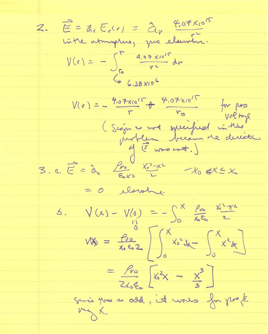
1 1. Coaxial Cable Electric Field Homework 4 Part One Due 14 October at 6:00 pm r a. Using the solution to problem 2 of HW3, write the electric field Er () of the CATV coaxial cable in full vector form (with unit vector) making sure you have provided an expression for all values of r. Also, write down the values of the inner and outer radii of the cable and its dielectric constant ε. b. Assuming that outer conductor is grounded, determine the voltage (electric potential) Vr ( ) for all values of r. Plot your solution as a function of radius. c. Show that your solution satisfies Laplace s Equation. 2. The Earth-Ionosphere Capacitor a. From the solution to problem 3 of HW2, write down the expression for the electric field vector Er r () as a function of radius in the region between the surface of the earth and the ionosphere. Be sure it is in full vector form. b. Assuming the surface of the earth is grounded, determine the voltage (electric potential) Vr ( ) for all values of r. Plot your solution as a function of radius. c. Show that your solution satisfies Laplace s Equation. 3. The Electric Field and Potential of a Distribution a. The volume charge distribution in the planar structure of problem 4, HW3 is reproduced below. From r the solution to this problem, write down the electric field as a function of x Ex ( ) in full vector form. ρ vo ρ v ( x) -x o x o x - ρ vo b. Assuming that the voltage is equal to zero at x=0, determine the voltage as a function of x V ( x)for all values of x. Plot your solution. Hint: to use Matlab for the plot, you will have to pick numerical values for the unspecified constants. c. Show that your solution for V ( x)satisfies Poisson s Equation. 1
2 Most of the solution for problem 1 is found on the handwritten pages that follow. The plotting can be done by Matlab. % Problem 1 a=.00051;b= ; epsr=1.38;epso=8.95e-12; Vo=546*log(b/a);%Voltage on Inner Conductor r0=[a:(b-a)/100:b];v0=546.*log(b./r0);%space between conductors r1=[0:(b-a)/100:a];for i=1:29;v1(i)=vo;end;%inside Inner Conductor r2=[b:(b-a)/100:2*b];for j=1:129;v2(j)=0;end%outside Conductor and Outside r=[r1 r0 r2];v=[v1 V0 V2]; %Plotting plot(r,v);grid;title('coaxial Cable Voltage');xlabel('Radius');ylabel('Volts'); 900 Coaxial Cable Voltage Volts Radius x 10-3 Note that the voltage is a constant for both conducting regions and varies as ln(b/r) in between the conductors (in the insulator region). 2
3 % Problem 2 re=6.38e6;ri=re+1e5;rs=[re:1e3:ri];rp=[0:1e3:1e5]; Vei=4.07e15.*((rs).^(-1)+(re).^(-1)); plot(rp,vei);grid;title('voltage in Atmosphere');xlabel('Altitude');ylabel('Volts'); x 109 Voltage in Atmosphere Volts Altitude x
4 % Problem 3 % Choose a value for xo. Also let the charge density divided by epso = 1 xo=.01; x=[-xo:xo/50:xo]; Vx=0.5.*((xo.^2).*x-(x.^3)./3); plot(x,vx);grid;title('voltage');xlabel('x-axis');ylabel('volts'); 4 x 10⁻⁷ Voltage Volts x-axis For this plot, note the values used for the constants. 4
5 Homework 4 Part Two Due 21 October at 6:00 pm 4. Capacitance Measurements Repeat the experiment done the first day of class where you made a small capacitor from two twisted wires on a protoboard. (Use a length of 20-30cm.) Calculate the capacitance of your configuration (you will have to carefully measure the dimensions of the wires and their separation distance and record the numbers in your solution) and compare with the measurement using the impedance bridge. Remember to take into account the capacitance of the cable you use to connect to your wires. Set up the same circuit you used previously and scan the frequency from 10kHz to 15MHz. Take enough data points to show the general form of the frequency dependence of the input and output voltages. Before coming to class, setup the following simulation using PSpice and show it to a TA or instructor at the beginning of your assigned section. Then modify the simulation based on your measured capacitance and run it again. Compare your experimental results with your simulation. Ideally, plot your measured data on the PSpice plot. R1 C1 50 V 10pF V VOFF = 0 VAMPL = 1 FREQ = 1k V1 R2 11k R3 11k 0 See lecture 12 slides, examples 2 and 3 for the general method. Each line will be slightly different, depending on its length and the type of wire used. The capacitance obtained should be similar. Typical frequency response from PSpice is shown below. 1.0V 0.8V 0.6V 0.4V Note that the corner freq. for this circuit is 1 f = ( 2πRC) = 1.45MHz and one would expect. 0.2V 0V 10KHz 30KHz 100KHz 300KHz 1.0MHz 3.0MHz 10MHz 30MHz 100MHz V(C1:2) V(R2:1) Frequency 5
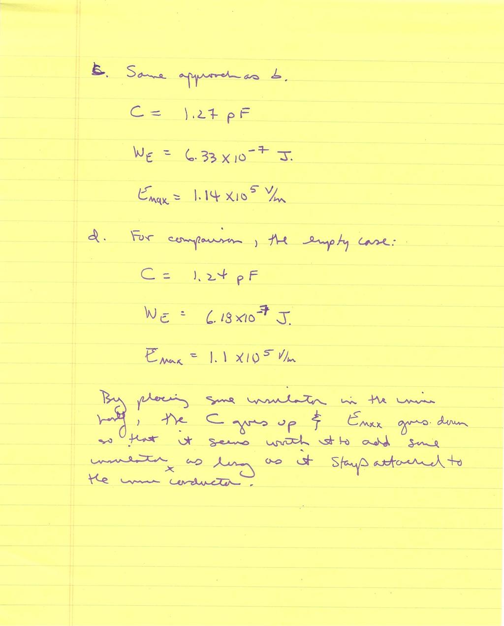
6 5. Capacitor Design Choices Assume that we have a limited amount of dielectric material and wish to investigate some choices for how we could use it in a simple capacitor configuration. a. Begin by determining the capacitance of the spherical structure below. Note that there are two different dielectric regions. Assume that the inner conductor voltage is V o and the outer conductor is grounded. You can use either the charge or energy method. a ε 1 c ε 2 b b. Now assume that the inner region is filled with an insulating material with ε1 = 6ε o and the outer region is airε = 2 εo ; a=1cm and b=10cm. Also assume the voltage on the inner conductor is 1000V and the outer conductor is grounded. Determine the capacitance and energy stored in this configuration. Also, determine the maximum value for the electric field magnitude. Assume that half of the volume between the two conductors is filled with insulator. c. Now assume that the outer region is filled with the insulating material so that ε1 = εo andε2 = 6ε o ; a=1cm and b=10cm. Also assume the voltage on the inner conductor is 1000V and the outer conductor is grounded. Determine the capacitance and energy stored in this configuration. Also, determine the maximum value for the electric field magnitude. Assume that half of the volume between the two conductors is filled with insulator. d. Discuss the tradeoffs between the three possible configurations, including the choice to not use the insulating material at all. 6
7 %Spherical Cap Problem %HW 4 Fall 2009 % K. A. Connor %Parameters a=.01;b=.1; c=((a^3+b^3)/2)^(1/3);%half the volume is filled with insulator r1=[a:(c-a)/100:c];r2=[c:(c-a)/100:b];r=[r1 r2]; epso=8.85e-12;vo=1000;%voltage on Inner Conductor. Outer is grounded. epsr=6; %Inner half filled with insulator C1=4*pi*epso/(1/(epsr*a)-1/(epsr*c)+1/c-1/b);Q1=C1*Vo;We1=0.5*C1*Vo^2; %E Field E11=Q1./(4.*pi.*epsr.*epso.*r1.^2);E12=Q1./(4.*pi.*epso.*r2.^2); E1=[E11 E12];E1max=max(E1); plot(r,e1);grid;xlabel('radius');ylabel('e Field');title('Insulator in Inner Region'); %Outer half filled with insulator C2=4*pi*epso/(1/(epsr*c)-1/(epsr*b)+1/a-1/c);Q2=C2*Vo;We2=0.5*C2*Vo^2; %E Field E21=Q2./(4.*pi.*epso.*r1.^2);E22=Q2./(4.*pi.*epsr.*epso.*r2.^2); E2=[E21 E22];E2max=max(E2); figure;plot(r,e2);grid;xlabel('radius');ylabel('e Field');title('Insulator in Outer Region'); %Neither half filled with insulator C=4*pi*epso/(1/a-1/b);Q=C*Vo;We=0.5*C*Vo^2; %E Field E=Q./(4.*pi.*epso.*r.^2);Emax=max(E); figure;plot(r,e);grid;xlabel('radius');ylabel('e Field');title('Insulator in Neither Region'); %Plot all Three Cases figure;plot(r,e,r,e1,r,e2);grid;xlabel('radius');ylabel('e Field');title('All Three Cases'); 10 x 104 Insulator in Inner Region 12 x 104 Insulator in Outer Region E Field 5 E Field Radius Radius 7
8 12 x 104 Insulator in Neither Region 12 x 104 All Three Cases E Field 6 E Field Radius Radius 6. Capacitance Using a Spreadsheet The device we are going to simulate is a variation of a capaciflector, which was invented by a NASA engineer. This uses a capacitor to determine the distance to a surface, usually as part of a robot obstacle sensor. For our purposes, you should use a 100x100 array (use rows 1to 101 and columns A to CW). The outer boundary cells should be grounded (V=0). The sensor electrode is relatively small (cells AT89 to BD89). There is also a reflector to force the field lines toward the surface to be measured (cells E97 to CS97). Both the sensor and reflector are at the same voltage (choose anything you like, but 10V works). However, we are only to be concerned with the capacitance of the sensor. [In application, the reflector is driven by a voltage follower connected to the sensor.] For your analysis, you can determine the charge on the sensor using the boundary condition method or the flux integral method. The latter should be more accurate, but the differences will not be large. All space is filled with air in this problem. a. Determine the charge on the sensor electrode for your choice of voltage. Use this to determine the capacitance of the configuration. Plot the equipotentials for this configuration, adding a few E field lines for clarity. Why are your results reasonable? The object whose position is to be measured is the top of the shield. Now we will move the top plate (add a grounded surface) at other locations to see how the capacitance will change. b. Repeat the calculations of part a for three additional cases: a grounded plane at row 26, 51 and 76, respectively. For each case, plot the equipotentials, adding a few E field lines for clarity. Why are your results reasonable? 8
9 For your analysis, please explain each step, especially if you use the spreadsheet to do most of the work. Extra Credit: Assume that the purpose of the moveable top plate is to separate a region filled with water from the air filled space just analyzed. Now also assume that the water leaks into the chamber (somehow). Consider two cases: one where the water fills the chamber up to row 95 and one where it fills the chamber up to row 76. Determine the capacitance for both cases. Use a relative permittivity of 81 for water. Only consider the situation where the top of the chamber is in its original position (top row). Discuss your results. 9
10 S100 S97 S94 S91 S88 S85 S82 S79 S76 S73 S70 S67 S64 S61 S58 S55 S52 S49 S46 S43 S40 S37 S34 S31 S S25 S22 S19 S16 S13 S10 S7 S4 S1 Shield Voltage 0 Electrode Voltage 10 Capacitance Calc Using Flux to Find Average Inner Voltage Average Outer Voltage Step Size Average E Field E-10 Flux 6.71E-11 Per Unit 6.71E E-12 The calculations done in Excel to determine the charge on the sensor for the given voltage are shown above. Note that two voltage averages are taken and the difference between them gives the average E field normal to the surface. From E we get D, which, when multiplied by the area, gives the flux. The flux is equal to the charge. 10
11 The following table shows the region around the sensor electrode. The electric flux was determined through a surface that surrounds the sensor. This is more accurate than the surface charge method, but here the difference is not great The surface charge method is also used. Capactiance Using Surface Average Voltage Average E Field E Per Unit 6.03E E-12 11
12 1 4 7 The following info is for the other three locations for the grounded top of the chamber. S100 S97 S94 S91 S88 S85 S82 S79 S76 S73 S70 S67 S64 S61 S58 S55 S52 S49 S46 S43 S40 S37 S34 S31 S S25 S22 S19 S16 S13 S10 S7 S4 S Capacitance Calc Using Flux to Find Average Inner Voltage Average Outer Voltage Step Size Average E Field E-10 Flux 1.68E-10 Per Unit 1.68E E-11 Capactiance Using Surface Average Voltage Average E Field E Per Unit 1.55E E-11 12
13 S100 S97 S94 S91 S88 S85 S82 S79 S76 S73 S70 S67 S64 S61 S58 S55 S52 S49 S46 S43 S40 S37 S34 S31 S S25 S22 S19 S16 S13 S10 S7 S4 S1 Capacitance Calc Using Flux to Find Average Inner Voltage Average Outer Voltage Step Size Average E Field E-10 Flux 7.97E-11 Per Unit 7.97E E-12 Capactiance Using Surface Average Voltage Average E Field E Per Unit 7.21E E-12 13
14 S100 S97 S94 S91 S88 S85 S82 S79 S76 S73 S70 S67 S64 S61 S58 S55 S52 S49 S46 S43 S40 S37 S34 S31 S S25 S22 S19 S16 S13 S10 S7 S4 S1 Capacitance Calc Using Flux to Find Average Inner Voltage Average Outer Voltage Step Size Average E Field E-10 Flux 6.74E-11 Per Unit 6.74E E-12 Capactiance Using Surface Average Voltage Average E Field E Per Unit 6.05E E-12 14
15 Redoing the first case, just to check to see if the structure is really sensitive to the change in top plate location: Capacitance Calc Using Flux to Find Average Inner Voltage Average Outer Voltage Step Size Average E Field E-10 Flux 6.73E-11 Per Unit 6.73E E-12 Capactiance Using Surface Average Voltage Average E Field E Per Unit 6.05E E-12 Thus, we see no change at all so this is probably not in the range where one can measure any real change. 15
16 1 4 7 Extra Credit: S100 S97 S94 S91 S88 S85 S82 S79 S76 S73 S70 S67 S64 S61 S58 S55 S52 S49 S46 S43 S40 S37 S34 S31 S28 S S22 S19 S16 S13 S10 S7 S4 S Capacitance Calc Using Flux to Find Average Inner Voltage Average Outer Voltage Step Size Average E Field E-09 Flux 1.26E-09 Per Unit 1.26E E-10 Capactiance Using Surface Average Voltage Average E Field E Per Unit 1.01E E-10 16
17 S100 S97 S94 S91 S88 S85 S82 S79 S76 S73 S70 S67 S64 S61 S58 S55 S52 S49 S46 S43 S40 S37 S34 S31 S28 S S22 S19 S16 S13 S10 S7 S4 S1 Capacitance Calc Using Flux to Find Average Inner Voltage Average Outer Voltage Step Size Average E Field E-11 Flux 5.42E-11 Per Unit 5.42E E-12 Capactiance Using Surface Average Voltage Average E Field E Per Unit 5.03E E-12 17

18
19

20

21

22
23
No prep assignment to do, but here are four questions anyway.
 Preparation Assignments for Homework #3 Due at the start of class. Reading Assignments Please see the handouts for each lesson for the reading assignments. 3,4 February Lesson 2.5 No prep assignment to
o Two-wire transmission line (end view is shown, the radius of the conductors = a, the distance between the centers of the two conductors = d)
") Homework 2 Due Monday, 14 June 1. There is a small number of simple conductor/dielectric configurations for which we can relatively easily find the capacitance. Students of electromagnetics should be sure
Homework 2 Due Monday, 14 June 1. There is a small number of simple conductor/dielectric configurations for which we can relatively easily find the capacitance. Students of electromagnetics should be sure
Lecture 15 Perfect Conductors, Boundary Conditions, Method of Images
 Lecture 15 Perfect Conductors, Boundary Conditions, Method of Images Sections: 5.4, 5.5 Homework: See homework file Perfect Conductors 1 metals such as Cu, Ag, Al are closely approximated by the concept
NR/RR. Set No. 2 CODE NO: NR/RR210204
 Set No. 2 II B.Tech I Semester Examinations,May 2011 ELECTROMAGNETIC FIELDS Electrical And Electronics Engineering Time: 3 hours Max Marks: 80 Answer any FIVE Questions All Questions carry equal marks
Physics 212. Lecture 7. Conductors and Capacitance. Physics 212 Lecture 7, Slide 1
 Physics 212 Lecture 7 Conductors and Capacitance Physics 212 Lecture 7, Slide 1 Conductors The Main Points Charges free to move E = 0 in a conductor Surface = Equipotential In fact, the entire conductor
Homework 5 Due 28 October at 6:00 pm
 1. Resistance Calculations Homework 5 Due 28 October at 6:00 pm Plus Electrode Minus Electrode Assume that we have a thin conductor deposited onto the surface of a plastic board (as on a printed circuit
Today s agenda: Capacitors and Capacitance. You must be able to apply the equation C=Q/V.
 Today s agenda: Capacitors and Capacitance. You must be able to apply the equation C=Q/V. Capacitors: parallel plate, cylindrical, spherical. You must be able to calculate the capacitance of capacitors
HIGH VOLTAGE TECHNIQUES Basic Electrode Systems (3)
") HIGH VOLTAGE TECHNIQES Basic Electrode Systems (3) Assistant Professor Suna BOLAT KRÖGER Eastern Mediterranean niversity Department of Electric & Electronic Engineering 1 Basic electrode systems Different
HIGH VOLTAGE TECHNIQES Basic Electrode Systems (3) Assistant Professor Suna BOLAT KRÖGER Eastern Mediterranean niversity Department of Electric & Electronic Engineering 1 Basic electrode systems Different
PH213 Chapter 24 Solutions
 PH213 Chapter 24 Solutions 24.12. IDENTIFY and S ET UP: Use the expression for derived in Example 24.4. Then use Eq. (24.1) to calculate Q. E XECUTE: (a) From Example 24.4, The conductor at higher potential
Physics Electricity & Op-cs Lecture 8 Chapter 24 sec Fall 2017 Semester Professor
 Physics 24100 Electricity & Op-cs Lecture 8 Chapter 24 sec. 1-2 Fall 2017 Semester Professor Kol@ck How Much Energy? V 1 V 2 Consider two conductors with electric potentials V 1 and V 2 We can always pick
Chapter 24 Capacitance and Dielectrics
 Chapter 24 Capacitance and Dielectrics 1 Capacitors and Capacitance A capacitor is a device that stores electric potential energy and electric charge. The simplest construction of a capacitor is two parallel
COLLEGE PHYSICS Chapter 19 ELECTRIC POTENTIAL AND ELECTRIC FIELD
 COLLEGE PHYSICS Chapter 19 ELECTRIC POTENTIAL AND ELECTRIC FIELD Electric Potential Energy and Electric Potential Difference It takes work to move a charge against an electric field. Just as with gravity,
Phy207 Exam II (Form1) Professor Zuo Fall Semester Signature: Name:
 Professor Zuo Fall Semester Signature: Name:") Phy207 Exam II (Form1) Professor Zuo Fall Semester 2015 On my honor, I have neither received nor given aid on this examination Signature: Name: #1 14 #15 ID number: Total Enter your name and Form 1 (FM1)
Phy207 Exam II (Form1) Professor Zuo Fall Semester 2015 On my honor, I have neither received nor given aid on this examination Signature: Name: #1 14 #15 ID number: Total Enter your name and Form 1 (FM1)
Exam 2 Practice Problems Part 1
 MASSACHUSETTS INSTITUTE OF TECHNOLOGY Department of Physics Exam 2 Practice Problems Part 1 Problem 1 Electric Field and Charge Distributions from Electric Potential An electric potential V ( z ) is described
Review. Spring Semester /21/14. Physics for Scientists & Engineers 2 1
 Review Spring Semester 2014 Physics for Scientists & Engineers 2 1 Notes! Homework set 13 extended to Tuesday, 4/22! Remember to fill out SIRS form: https://sirsonline.msu.edu Physics for Scientists &
Physics Exam II
 Physics 208 - Exam II Spring 2018 (all sections) - March 5, 2018. Please fill out the information and read the instructions below, but do not open the exam until told to do so. Rules of the exam: 1. You
Capacitors (Chapter 26)
") Capacitance, C Simple capacitive circuits Parallel circuits Series circuits Combinations Electric energy Dielectrics Capacitors (Chapter 26) Capacitors What are they? A capacitor is an electric device
Capacitance, C Simple capacitive circuits Parallel circuits Series circuits Combinations Electric energy Dielectrics Capacitors (Chapter 26) Capacitors What are they? A capacitor is an electric device
Physics (
 Question 2.12: A charge of 8 mc is located at the origin. Calculate the work done in taking a small charge of 2 10 9 C from a point P (0, 0, 3 cm) to a point Q (0, 4 cm, 0), via a point R (0, 6 cm, 9 cm).
Physics 122 Spring 2012 Test 2
 Name: Instructions: Physics 122 Spring 2012 Test 2 There are some useful tables at the end of this exam paper. You may use a calculator and your 3x5 index card. Please ATTACH your index card to the test
Physics 202, Exam 1 Review
 Physics 202, Exam 1 Review Logistics Topics: Electrostatics (Chapters 21-24.6) Point charges: electric force, field, potential energy, and potential Distributions: electric field, electric potential. Interaction
Homework. Reading: Chap. 29, Chap. 31 and Chap. 32. Suggested exercises: 29.17, 29.19, 29.22, 29.23, 29.24, 29.26, 29.27, 29.29, 29.30, 29.31, 29.
 Homework Reading: Chap. 29, Chap. 31 and Chap. 32 Suggested exercises: 29.17, 29.19, 29.22, 29.23, 29.24, 29.26, 29.27, 29.29, 29.30, 29.31, 29.32 Problems: 29.49, 29.51, 29.52, 29.57, 29.58, 29.59, 29.63,
Lecture 18 Capacitance and Conductance
 Lecture 18 Capacitance and Conductance Sections: 6.3, 6.4, 6.5 Homework: See homework file Definition of Capacitance capacitance is a measure of the ability of the physical structure to accumulate electrical
Chapter 24 Capacitance and Dielectrics
 Chapter 24 Capacitance and Dielectrics Lecture by Dr. Hebin Li Goals for Chapter 24 To understand capacitors and calculate capacitance To analyze networks of capacitors To calculate the energy stored in
ELECTRO MAGNETIC FIELDS
 SET - 1 1. a) State and explain Gauss law in differential form and also list the limitations of Guess law. b) A square sheet defined by -2 x 2m, -2 y 2m lies in the = -2m plane. The charge density on the
Potentials and Fields
 Potentials and Fields Review: Definition of Potential Potential is defined as potential energy per unit charge. Since change in potential energy is work done, this means V E x dx and E x dv dx etc. The
Practice Test 2 - Physics Fall 2016 October 12, Last Name: First Name:
 Practice Test 2 - Physics 2113 - Fall 2016 October 12, 2016 Last Name: First Name: TTH MWF 12:0 pm Wilde Sec. 6 8:30am Rupnik Sec. 1 1:30 pm Zuniga-Hansen Sec. 7 10:30am Stadler Sec. 2 12:30pm Blackmon
Do not fill out the information below until instructed to do so! Name: Signature: Section Number:
 Do not fill out the information below until instructed to do so! Name: Signature: E-mail: Section Number: No calculators are allowed in the test. Be sure to put a box around your final answers and clearly
Physics (
 Exercises Question 2: Two charges 5 0 8 C and 3 0 8 C are located 6 cm apart At what point(s) on the line joining the two charges is the electric potential zero? Take the potential at infinity to be zero
PHYS208 RECITATIONS PROBLEMS: Week 2. Gauss s Law
 Gauss s Law Prob.#1 Prob.#2 Prob.#3 Prob.#4 Prob.#5 Total Your Name: Your UIN: Your section# These are the problems that you and a team of other 2-3 students will be asked to solve during the recitation
Capacitance & Capacitors, Energy Stored in Capacitors Challenge Problems
 Problem 1: Capacitance & Capacitors, Energy Stored in Capacitors Challenge Problems A parallel-plate capacitor is charged to a potential V 0, charge Q 0 and then disconnected from the battery. The separation
Consider a point P on the line joining the two charges, as shown in the given figure.
 Question 2.1: Two charges 5 10 8 C and 3 10 8 C are located 16 cm apart. At what point(s) on the line joining the two charges is the electric potential zero? Take the potential at infinity to be zero.
Physics 196 Final Test Point
 Physics 196 Final Test - 120 Point Name You need to complete six 5-point problems and six 10-point problems. Cross off one 5-point problem and one 10-point problem. 1. Two small silver spheres, each with
Physics 213: General Physics Fall :30 AM Lecture
 Physics 213: General Physics Fall 2004 9:30 AM Lecture Midterm I Solutions Tuesday, September 21, 2004 Chem-Phys 153 Name (print): Signature: Student Number: Your Seat Number (on back of chair): 1. Immediately
PHYSICS 241 TEST 1 Monday, February 17, 2003
 PHYSICS 241 TEST 1 Monday, February 17, 2003 This 15-question test (each question is worth approximately 6.67 points) is worth 100 points, each question is weighted equally. Please fill out the answer
Physics 202, Exam 1 Review
 Physics 202, Exam 1 Review Logistics Topics: Electrostatics + Capacitors (Chapters 21-24) Point charges: electric force, field, potential energy, and potential Distributions: electric field, electric potential.
Chapter 10: Air Breakdown
 ELECTOMAGNETIC COMPATIBILITY HANDBOOK 1 Chapter 10: Air Breakdown 10.1 How is a silicon controlled rectifier (SC) similar to the breakdown of a gas? 10.S By comparing to an actual Paschen curve for air
Exam 1 Solutions. The ratio of forces is 1.0, as can be seen from Coulomb s law or Newton s third law.
 Prof. Eugene Dunnam Prof. Paul Avery Feb. 6, 007 Exam 1 Solutions 1. A charge Q 1 and a charge Q = 1000Q 1 are located 5 cm apart. The ratio of the electrostatic force on Q 1 to that on Q is: (1) none
Capacitance and capacitors. Dr. Loai Afana
 apacitance and capacitors apacitors apacitors are devices that store energy in an electric field. apacitors are used in many every-day applications Heart defibrillators amera flash units apacitors are
Columbia University Department of Physics QUALIFYING EXAMINATION
 Columbia University Department of Physics QUALIFYING EXAMINATION Monday, January 9, 2012 3:10PM to 5:10PM Classical Physics Section 2. Electricity, Magnetism & Electrodynamics Two hours are permitted for
Energy stored in a capacitor W = \ q V. i q1. Energy density in electric field i. Equivalent capacitance of capacitors in series
 The Language of Physics Cwcihor Two conductors of any size or shape carrying equal and opposite charges are called a capacitor. The charge on the capacitor is directly proportional to the potential difference
Lecture 13: Electromagnetic Theory Professor D. K. Ghosh, Physics Department, I.I.T., Bombay. Poisson s and Laplace s Equations
 Poisson s and Laplace s Equations Lecture 13: Electromagnetic Theory Professor D. K. Ghosh, Physics Department, I.I.T., Bombay We will spend some time in looking at the mathematical foundations of electrostatics.
Chapter 24 Capacitance and Dielectrics
 Chapter 24 Capacitance and Dielectrics 1 Capacitors and Capacitance A capacitor is a device that stores electric potential energy and electric charge. The simplest construction of a capacitor is two parallel
Lecture 9 Electric Flux and Its Density Gauss Law in Integral Form
 Lecture 9 Electric Flux and Its Density Gauss Law in Integral Form ections: 3.1, 3.2, 3.3 Homework: ee homework file Faraday s Experiment (1837), Electric Flux ΨΨ charge transfer from inner to outer sphere
LAB 5. INTRODUCTION Finite Difference Method
 LAB 5 In previous two computer labs, you have seen how the analytical techniques for solving electrostatic problems can be approximately solved using numerical methods. For example, you have approximated
EE1305/EE1105 Intro to Electrical and Computer Engineering Lecture Week 6
 EE1305/EE1105 Intro to Electrical and Computer Engineering Lecture Week 6 Homework Passive Components Capacitors RC Filters fc Calculations Bode Plots Module III Homework- due 2/20 (Najera), due 2/23 (Quinones)
Homework assignment from , MEMS Capacitors lecture
 Homework assignment from 05-02-2006, MEMS Capacitors lecture 1. Calculate the capacitance for a round plate of 100µm diameter with an air gap space of 2.0 µm. C = e r e 0 * A/d (1) e 0 = 8.85E-12 F/m e
Q1. A wave travelling along a string is described by
 Coordinator: Saleem Rao Wednesday, May 24, 2017 Page: 1 Q1. A wave travelling along a string is described by y( x, t) = 0.00327 sin(72.1x 2.72t) In which all numerical constants are in SI units. Find the
Mid Term Exam. Electricity and Magnetism PHY204
 Attempt all Question Time Allowed: 2h 15 minutes Mid Term Exam Electricity and Magnetism PHY204 Instructor: Dr. Anzar Khaliq You are provided with a formula sheet. No other formulas outside of that sheet
iclicker A metal ball of radius R has a charge q. Charge is changed q -> - 2q. How does it s capacitance changed?
 1 iclicker A metal ball of radius R has a charge q. Charge is changed q -> - 2q. How does it s capacitance changed? q A: C->2 C0 B: C-> C0 C: C-> C0/2 D: C->- C0 E: C->-2 C0 2 iclicker A metal ball of
W05D1 Conductors and Insulators Capacitance & Capacitors Energy Stored in Capacitors
 W05D1 Conductors and Insulators Capacitance & Capacitors Energy Stored in Capacitors W05D1 Reading Assignment Course Notes: Sections 3.3, 4.5, 5.1-5.4 1 Outline Conductors and Insulators Conductors as
Physics 42 Exam 2 PRACTICE Name: Lab
 Physics 42 Exam 2 PRACTICE Name: Lab 1 2 3 4 Conceptual Multiple Choice (2 points each) Circle the best answer. 1.Rank in order, from brightest to dimmest, the identical bulbs A to D. A. C = D > B > A
PHYS 1444 Section 004 Lecture #22
 PHYS 1444 Section 004 Lecture #22 Monday, April 23, 2012 Dr. Extension of Ampere s Law Gauss Law of Magnetism Maxwell s Equations Production of Electromagnetic Waves Today s homework is #13, due 10pm,
Electric Fields and Potentials
 Electric Fields and Potentials INTRODUCTION This experiment is intended to illustrate the concepts of electric fields and electric potentials and how they are related to the charge distribution that produces
Sharpen thinking about connections among electric field, electric potential difference, potential energy
 PHYS 2015 -- Week 6 Sharpen thinking about connections among electric field, electric potential difference, potential energy Apply the ideas to capacitance and the parallel plate capacitor For exclusive
Physics 208: Electricity and Magnetism Final Exam, Secs May 2003 IMPORTANT. Read these directions carefully:
 Physics 208: Electricity and Magnetism Final Exam, Secs. 506 510 2 May 2003 Instructor: Dr. George R. Welch, 415 Engineering-Physics, 845-7737 Print your full name: Sign your name: Please fill in your
General Physics II Lab EM2 Capacitance and Electrostatic Energy
 Purpose General Physics II Lab General Physics II Lab EM2 Capacitance and Electrostatic Energy In this experiment, you will examine the relationship between charge, voltage and capacitance of a parallel
Capacitors. Gauss s law leads to
 Capacitors The electric field lines starts from a positive charge and ends at a negative charge. Gauss s law leads to If the two charge sheets are on two conductor plates, you have a parallel-plate capacitor.
BE 3600 BIOMEDICAL INSTRUMENTATION (LAB) - WEEK 2
 - WEEK 2") BE 3600 BIOMEDICAL INSTRUMENTATION (LAB) - WEEK 2 Principles of Biosensors OBJECTIVE: Learn the various modalities for construction of sensors utilizing electrical and optical measurement techniques. EXPERIMENT
BE 3600 BIOMEDICAL INSTRUMENTATION (LAB) - WEEK 2 Principles of Biosensors OBJECTIVE: Learn the various modalities for construction of sensors utilizing electrical and optical measurement techniques. EXPERIMENT
Electrostatics: Electrostatic Devices
 Electrostatics: Electrostatic Devices EE331 Electromagnetic Field Theory Outline Laplace s Equation Derivation Meaning Solving Laplace s equation Resistors Capacitors Electrostatics -- Devices Slide 1
Coulomb s Law Pearson Education Inc.
 Coulomb s Law Coulomb s Law: The magnitude of the electric force between two point charges is directly proportional to the product of their charges and inversely proportional to the square of the distance
Agenda for Today. Elements of Physics II. Capacitors Parallel-plate. Charging of capacitors
 Capacitors Parallel-plate Physics 132: Lecture e 7 Elements of Physics II Charging of capacitors Agenda for Today Combinations of capacitors Energy stored in a capacitor Dielectrics in capacitors Physics
ELECTROMANETIC PULSE PROPAGATION IN A COAXIAL CABLE
 ELECTROMANETIC PULSE PROPAGATION IN A COAXIAL CABLE The mechanical waves on a stretched string are easily generated and observed but not easily studied in quantitative detail. The propagating waves in
Capacitors And Dielectrics
 1 In this small e-book we ll learn about capacitors and dielectrics in short and then we ll have some questions discussed along with their solutions. I ll also give you a practices test series which you
Physics 420 Fall 2004 Quiz 1 Wednesday This quiz is worth 6 points. Be sure to show your work and label your final answers.
 Quiz 1 Wednesday This quiz is worth 6 points. Be sure to show your work and label your final answers. 1. A charge q 1 = +5.0 nc is located on the y-axis, 15 µm above the origin, while another charge q
Physics 240 Fall 2003: Final Exam. Please print your name: Please list your discussion section number: Please list your discussion instructor:
 Physics 40 Fall 003: Final Exam Please print your name: Please list your discussion section number: Please list your discussion instructor: Form #1 Instructions 1. Fill in your name above. This will be
Sources of Potential (EMF)
") Sources of Potential (EMF) A source of potential difference is sometimes called a source of EMF, a widely used term, which stands for ElectroMotive Force. Your author points out that this is an outdated
Sources of Potential (EMF) A source of potential difference is sometimes called a source of EMF, a widely used term, which stands for ElectroMotive Force. Your author points out that this is an outdated
The Basic Capacitor. Dielectric. Conductors
 Chapter 9 The Basic Capacitor Capacitors are one of the fundamental passive components. In its most basic form, it is composed of two conductive plates separated by an insulating dielectric. The ability
Electric Field Mapping
 PC1143 Physics III Electric Field Mapping 1 Objectives Map the electric fields and potentials resulting from three different configurations of charged electrodes rectangular, concentric, and circular.
1. Short Answer (25 points total)
") Physics 116b First Practice Examination Due September 19, 2001 Name: Please circle your section: Section 1 Section 2 Section 3 Section 4 I nstructions This is practice for a one hour, closed book examination.
Physics 116b First Practice Examination Due September 19, 2001 Name: Please circle your section: Section 1 Section 2 Section 3 Section 4 I nstructions This is practice for a one hour, closed book examination.
Phys222 W16 Exam 2: Chapters Key. Name:
 Name: Please mark your answer here and in the scantron. A positively charged particle is moving in the +y-direction when it enters a region with a uniform electric field pointing in the +y-direction. Which
IMPORTANT Read these directions carefully:
 Physics 208: Electricity and Magnetism Common Exam 2, October 17 th 2016 Print your name neatly: First name: Last name: Sign your name: Please fill in your Student ID number (UIN): _ - - Your classroom
iclicker A device has a charge q=10 nc and a potential V=100V, what s its capacitance? A: 0.1 nf B: 1nF C: 10nF D: F E: 1F
 Lecture 8 iclicker A device has a charge q=10 nc and a potential V=100V, what s its capacitance? A: 0.1 nf B: 1nF C: 10nF D: 10 10 F E: 1F iclicker A device has a charge q=10 nc and a potential V=100V,
which checks. capacitance is determined entirely by the dimensions of the cylinders.
 4.3. IDENTIFY and SET UP: It is a parallel-plate air capacitor, so we can apply the equations of Section 4.. EXEUTE: (a) (b) = ε 0 A d (c) V ab so Q V = so 0 ab V ab 6 Q 0. 48 0 = = = 604 V. 45 0 F 3 d
ECE 6340 Fall Homework 2. Please do the following problems (you may do the others for practice if you wish): Probs. 1, 2, 3, 4, 5, 6, 7, 10, 12
: Probs. 1, 2, 3, 4, 5, 6, 7, 10, 12") ECE 634 Fall 16 Homework Please do the following problems (you may do the others for practice if you wish: Probs. 1,, 3, 4, 5, 6, 7, 1, 1 1 Consider two parallel infinite wires in free space each carrying
ECE 634 Fall 16 Homework Please do the following problems (you may do the others for practice if you wish: Probs. 1,, 3, 4, 5, 6, 7, 1, 1 1 Consider two parallel infinite wires in free space each carrying
Electric Potential Practice Problems
 Electric Potential Practice Problems AP Physics Name Multiple Choice 1. A negative charge is placed on a conducting sphere. Which statement is true about the charge distribution (A) Concentrated at the
Agenda for Today. Elements of Physics II. Capacitors Parallel-plate. Charging of capacitors
 Capacitors Parallel-plate Physics 132: Lecture e 7 Elements of Physics II Charging of capacitors Agenda for Today Combinations of capacitors Energy stored in a capacitor Dielectrics in capacitors Physics
Class 5 : Conductors and Capacitors
 Class 5 : Conductors and Capacitors What is a conductor? Field and potential around conductors Defining and evaluating capacitance Potential energy of a capacitor Recap Gauss s Law E. d A = Q enc and ε
General Physics II. Conducting concentric spheres Two concentric spheres of radii R and r. The potential difference between the spheres is
 apacitors and Dielectrics The ideas of energy storage in E-fields can be carried a step further by understanding the concept of "apacitance" onsider a sphere with a total charge, Q, and a radius, R From
Electric Potential Energy Chapter 16
 Electric Potential Energy Chapter 16 Electric Energy and Capacitance Sections: 1, 2, 4, 6, 7, 8, 9 The electrostatic force is a conservative force It is possible to define an electrical potential energy
Week 5 - Dielectrica, Resistance and Resistivity
 Week 5 - Dielectrica, Resistance and Resistivity Further, the dignity of the science itself seems to require that every possible means be explored for the solution of a problem so elegant and so celebrated.
Chapter 29. Electric Potential: Charged Conductor
 hapter 29 Electric Potential: harged onductor 1 Electric Potential: harged onductor onsider two points (A and B) on the surface of the charged conductor E is always perpendicular to the displacement ds
Demonstration 1: Faraday Ice Pail and Charge Production
 Osservazioni e Misure Lezioni I e II Laboratorio di Elettromagnetismo Demonstration 1: Faraday Ice Pail and Charge Production Equipment Required: Electrometer (ES-9078) Charge Producers (ES-9057B) Earth
1. zero. Where an electric field line crosses an equipotential surface, the angle between the field line and the equipotential is
 Week 5 Where an electric field line crosses an equipotential surface, the angle between the field line and the equipotential is 1. zero 2. between zero and 90 3. 90 4. not enough information given to
Look over. examples 1, 2, 3, 5, 6. Look over. Chapter 25 section 1-8. Chapter 19 section 5 Example 10, 11
 PHYS Look over hapter 5 section -8 examples,, 3, 5, 6 PHYS Look over hapter 7 section 7-9 Examples 8, hapter 9 section 5 Example 0, Things to Know ) How to find the charge on a apacitor. ) How to find
Designing Information Devices and Systems I Fall 2018 Lecture Notes Note Introduction to Capacitive Touchscreen
 EES 16A Designing Information Devices and Systems I Fall 2018 Lecture Notes Note 16 16.1 Introduction to apacitive Touchscreen We ve seen how a resistive touchscreen works by using the concept of voltage
WELCOME TO PERIOD 14. Homework Exercise #13 is due today. Watch video 3 Edison s Miracle of Light for class discussion next Tuesday or Wednesday.
 WELCOME TO PERIOD 14 Homework Exercise #13 is due today. Watch video 3 Edison s Miracle of Light for class discussion next Tuesday or Wednesday. PHYSICS 1103 PERIOD 14 What is an electric circuit? How
Physics 169. Luis anchordoqui. Kitt Peak National Observatory. Thursday, February 22, 18
 Physics 169 Kitt Peak National Observatory Luis anchordoqui 1 4.1 Capacitors A capacitor is a system of two conductors that carries equal and opposite charges A capacitor stores charge and energy in the
Friday July 11. Reminder Put Microphone On
 Friday July 11 8:30 AM 9:0 AM Catch up Lecture 3 Slide 5 Electron projected in electric field problem Chapter 23 Problem 29 Cylindrical shell problem surrounding wire Show Faraday Ice Pail no chrage inside
Capacitance. Chapter 21 Chapter 25. K = C / C o V = V o / K. 1 / Ceq = 1 / C / C 2. Ceq = C 1 + C 2
 = Chapter 21 Chapter 25 Capacitance K = C / C o V = V o / K 1 / Ceq = 1 / C 1 + 1 / C 2 Ceq = C 1 + C 2 Copyright 25-2 Capacitance 25.01 Sketch a schematic diagram of a circuit with a parallel-plate capacitor,
Chapter 25. Capacitance
 Chapter 25 Capacitance 25.2: Capacitance: 25.2: Capacitance: When a capacitor is charged, its plates have charges of equal magnitudes but opposite signs: q+ and q-. However, we refer to the charge of a
Capacitance and Dielectrics
 Chapter 24 Capacitance and Dielectrics PowerPoint Lectures for University Physics, Thirteenth Edition Hugh D. Young and Roger A. Freedman Lectures by Wayne Anderson Goals for Chapter 24 To understand capacitors
PHY101: Major Concepts in Physics I. Photo: J. M. Schwarz
 Welcome back to PHY101: Major Concepts in Physics I Photo: J. M. Schwarz Announcements In class today we will finish Chapter 17 on electric potential energy and electric potential and perhaps begin Chapter
Capacitance and Dielectrics
 Slide 1 / 39 Capacitance and Dielectrics 2011 by Bryan Pflueger Capacitors Slide 2 / 39 A capacitor is any two conductors seperated by an insulator, such as air or another material. Each conductor has
F 13. The two forces are shown if Q 2 and Q 3 are connected, their charges are equal. F 12 = F 13 only choice A is possible. Ans: Q2.
 Q1. Three fixed point charges are arranged as shown in Figure 1, where initially Q 1 = 10 µc, Q = 15 µc, and Q 3 = 5 µc. If charges Q and Q 3 are connected by a very thin conducting wire and then disconnected,
University of Saskatchewan Department of Electrical Engineering
 University of Saskatchewan Department of Electrical Engineering December 9,2004 EE30 1 Electricity, Magnetism and Fields Final Examination Professor Robert E. Johanson Welcome to the EE301 Final. This
PHYSICS 2B FINAL EXAM ANSWERS WINTER QUARTER 2010 PROF. HIRSCH MARCH 18, 2010 Problems 1, 2 P 1 P 2
 Problems 1, 2 P 1 P 1 P 2 The figure shows a non-conducting spherical shell of inner radius and outer radius 2 (i.e. radial thickness ) with charge uniformly distributed throughout its volume. Prob 1:
EIS of Organic Coatings and Paints
 EIS of Organic Coatings and Paints Introduction All My Impedance Spectra Look the Same! "I m an experienced polymer chemist. I m trying to use Electrochemical Impedance Spectroscopy (EIS) to predict the
2014 F 2014 AI. 1. Why must electrostatic field at the surface of a charged conductor be normal to the surface at every point? Give reason.
 2014 F 1. Why must electrostatic field at the surface of a charged conductor be normal to the surface at every point? Give reason. 2. Figure shows the field lines on a positive charge. Is the work done
Capacitors. Charging a Capacitor. Charge and Capacitance. L05: Capacitors and Inductors
 L05: Capacitors and Inductors 50 Capacitors 51 Outline of the lecture: Capacitors and capacitance. Energy storage. Capacitance formula. Types of capacitors. Inductors and inductance. Inductance formula.
Physics 102: Lecture 04 Capacitors (& batteries)
") Physics 102: Lecture 04 Capacitors (& batteries) Physics 102: Lecture 4, Slide 1 I wish the checkpoints were given to us on material that we learned from the previous lecture, rather than on material from
Physics 102: Lecture 04 Capacitors (& batteries) Physics 102: Lecture 4, Slide 1 I wish the checkpoints were given to us on material that we learned from the previous lecture, rather than on material from