FLOW MEASUREMENT INC 331 Industrial process measurement 2018
|
|
|
- Duane Reynard Walker
- 5 years ago
- Views:
Transcription

1 FLOW MEASUREMENT INC 331 Industrial process measurement
2 TABLE OF CONTENTS A. INTRODUCTION B. LOCAL FLOW MEASUREMENT B.1 Particle Image Velocimetry (PIV) B.2 Laser doppler anemometry (LDA) B.3 Hot-wire and Hot film anemometer C. GROSS VOLUME FLOW MEASUREMENT C.1 Differential Pressure flowmeters C.2 Variable-Area flowmeters C.3 Magnetic flowmeters C.4 Turbine flowmeters C.5 Oscillatory flowmeters C.6 Ultrasonic flowmeters C.7 Positive Displacement flowmeters C.8 Target flowmeters C.9 Open-channel flowmeters (no lecture) D. GROSS MASS FLOW MEASUREMENT D.1 The inferential mass flow measurement D.2 Coriolis flowmeter D.3 Thermal mass flowmeter E. METER SELECTION 2
3 PART A. INTRODUCTION 3
4 Flow rates: 1. Volumetric flowrate (volume/time) Units: m 3 /s, LPM, GPM, etc 2. Mass flowrate (mass/time) Units: g/s, kg/min, etc 4
5 A. INTRODUCTION : Physical properties of fluid Temperature Pressure Density Viscosity Influence of viscosity on Flowmeter Newtonian and Non- Newtonian fluid Electrical conductivity Sonic conductivity 5

6 A. INTRODUCTION : Physical properties of fluid Temperature Pressure Density Viscosity Influence of viscosity on Flowmeter Newtonian and Non- Newtonian fluid Electrical conductivity Sonic conductivity 6
7 A. INTRODUCTION : Physical properties of fluid Temperature Pressure Density Viscosity Influence of viscosity on Flowmeter Newtonian and Non- Newtonian fluid Electrical conductivity Sonic conductivity 7


8 A. INTRODUCTION : Physical properties of fluid Images - Laminar/Turbulent Flows Laser - induced florescence image of an incompressible turbulent boundary layer Laminar flow Simulation of turbulent flow coming out of a tailpipe Turbulent flow SOURCE: 8
9 A. INTRODUCTION : Physical properties of fluid Temperature Pressure Density Viscosity Influence of viscosity on Flowmeter Newtonian and Non- Newtonian fluid Electrical conductivity Sonic conductivity 9
10 A. INTRODUCTION :Fundamentals of flow measurement 10
11 A. INTRODUCTION :Flow profile and piping effects Laminar flow profile Turbulent flow profile Effect of a single piping elbow on flow profile 11
12 A. INTRODUCTION :Flow profile and piping effects Flowmeters are often requirements for lengths of straight downstream piping between the flowmeter and disturbance. 12
13 PART B. LOCAL FLOW MEASUREMENT 13


14 B. LOCAL FLOW :Particle Image Velocimetry (PIV) 3D FlowMaster PIV system setup Reacting flowfield of a flat counterflow burner Source: 14

 FLOW")

15 B. LOCAL FLOW :Particle Image Velocimetry (PIV) FLOW MEASUREMENT Source: 15


16 B. LOCAL FLOW :Particle Image Velocimetry (PIV) Source: 16
 Absolute measurement technique (no calibration required) Very high accuracy Very high spatial resolution due to small measurement volume Tracer particles are required Source:")
17 B. LOCAL FLOW : Laser doppler anemometry (LDA) Invented by Yeh and Cummins in 1964 Velocity measurements in Fluid Dynamics (gas, liquid) Up to 3 velocity components Non-intrusive measurements (optical technique) Absolute measurement technique (no calibration required) Very high accuracy Very high spatial resolution due to small measurement volume Tracer particles are required Source: 17
 Source: http://www.dantecdynamics.")
18 B. LOCAL FLOW : Laser doppler anemometry (LDA) Source: 18
 Detector Time Bragg Cell Laser measuring volume backscattered light Source: http://www.dantecdynamics.")
19 B. LOCAL FLOW : Laser doppler anemometry (LDA) Velocity = distance/time Flow with particles Signal Processor d (known) t (measured) Detector Time Bragg Cell Laser measuring volume backscattered light Source: 19


20 B. LOCAL FLOW : Laser doppler anemometry (LDA) Laser Doppler Anemometry can be used to investigate propulsion efficiency and cavitation. Measurement in a test engine using Laser Doppler Anemometry. Source: AVL-List Austria 20


21 B. LOCAL FLOW : Hot-wire anemometer The Hot-Wire Anemometer is the most well known thermal anemometer, and measures a fluid velocity by noting the heat convected away by the fluid. The core of the anemometer is an exposed hot wire either heated up by a constant current or maintained at a constant temperature. The heat lost to fluid convection is a function of the fluid velocity. 21

22 B. LOCAL FLOW : Hot-wire anemometer Source: 22


23 B. LOCAL FLOW :Multi-channel Hot-wire anemometer Source: 23
24 PART C. GROSS VOLUME FLOW MEASUREMENT 24

25 C. GROSS VOLUME FLOW :Differential pressure flowmeter The most commonly used differential pressure flowmeter type are: Orifice Venturi Nozzle Averaging Pitot tube Wedge meter 25


26 C. GROSS VOLUME FLOW :Differential pressure flowmeter Pressure contour and velocity profiles Source: 26

27 C. GROSS VOLUME FLOW :Differential pressure flowmeter Source: 27
28 C. GROSS VOLUME FLOW :Differential pressure flowmeter 28


29 C. GROSS VOLUME FLOW :Differential pressure flowmeter C.1.1 Orifice 29


30 C. GROSS VOLUME FLOW :Differential pressure flowmeter Orifice plate & differential pressure transmitter Source: 30

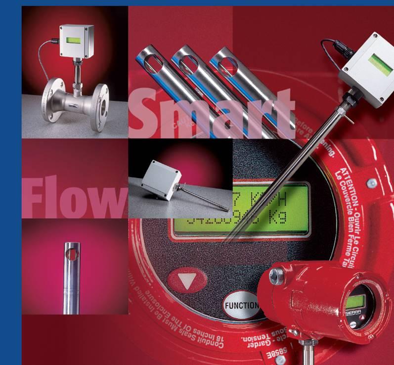
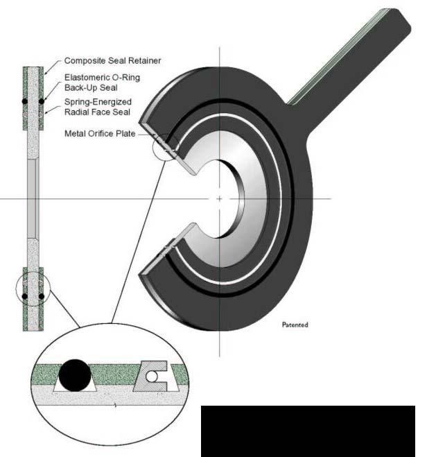
31 C. GROSS VOLUME FLOW :Differential pressure flowmeter Compact Orifice & Installation 31


32 C. GROSS VOLUME FLOW :Differential pressure flowmeter C.1.2 Venturi A venture is a restriction with a relatively long passage with smooth entry and exit. It produces less permanent pressure loss than similar sized orifice but it is more expensive. It often used in dirty flow streams. 32


33 C. GROSS VOLUME FLOW :Differential pressure flowmeter C.1.3 Nozzle Flow nozzles have a smooth entry and shape exit. The permanent pressure loss pf a nozzle is of the same order as that of an orifice, but it can handle dirty and abrasive fluid better than and orifice can. It often used in steam service because of their rigidity, which makes them more stable at high temperature and velocities than orifice. 33
34 C. GROSS VOLUME FLOW :Differential pressure flowmeter Nozzle installation 34


35 C. GROSS VOLUME FLOW :Differential pressure flowmeter C.1.4 Averaging pitot tube 35

36 C. GROSS VOLUME FLOW :Differential pressure flowmeter C.1.5 Wedge meter 36
37 C. GROSS VOLUME FLOW :Differential pressure flowmeter Primary elements Orifice Venturi Nozzle Averaging Pitot tube Wedge meter Elbow Score Phase Condition Cryogenic Gas Liquid Steam Liquid Slurry : Recommended : Limited applicability Clean Dirty Clean Dirty Viscous Saturated Superheated Corrosive Abrasive Elbow 37

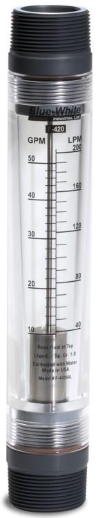
38 C. GROSS VOLUME FLOW :Variable-area flowmeter 38
39 C. GROSS VOLUME FLOW :Variable-area flowmeter 39
40 C. GROSS VOLUME FLOW :Variable-area flowmeter 40
41 C. GROSS VOLUME FLOW :Variable-area flowmeter 41


42 C. GROSS VOLUME FLOW :Variable-area flowmeter Score Phase Condition Gas Clean Liquid Gas Liquid Clean Open Channel Dirty Corrosive Steam Dirty Recommended Limited applicability Saturated 42


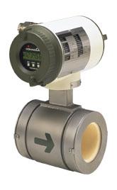
43 C. GROSS VOLUME FLOW :Magnetic flowmeter Magnetic flowmeters, also known as electromagnetic flowmeters or induction flowmeters, obtain the flow velocity by measuring the changes of induced voltage of the conductive fluid passing across a controlled magnetic field. Flangeless type 43
44 C. GROSS VOLUME FLOW :Magnetic flowmeter According to Faraday's law of electromagnetic induction: any change in the magnetic field with time induces an electric field perpendicular to the changing magnetic field: where E is the voltage of induced current, B is the external magnetic field, A is the corss section area of the coil, N is the number of turns of the coil, is the magnetic flux, and finally the negative sign indicates that the current induced will create another magnetic field opposing to the buildup of magnetic field in the coil based on Lenz's law. When applying the above equation to magnetic flowmeters, the number of turns N and the strength of the magnetic field B are fixed. The Faraday's law becomes where D is the distance between the two electrodes (the length of conductor), and V is the flow velocity. Source : 44
: Inlet run: 3D-5D Outlet run: 2D Elbow,3D Pump,10D Control valve, 10D (should be located downstream of the flowmeter)")
45 C. GROSS VOLUME FLOW :Magnetic flowmeter Straight run upstream of well-designed magnetic flowmeter from the centre of meter for standard accuracy (1% rate): Inlet run: 3D-5D Outlet run: 2D Elbow,3D Pump,10D Control valve, 10D (should be located downstream of the flowmeter) 45
46 C. GROSS VOLUME FLOW :Magnetic flowmeter Score Phase Condition Liquid Clean Corrosive Dirty Viscous Slurry Abrasive Fibrous Liquid Non-Newtonian : Recommended : Limited applicability Open Channel 46


47 C. GROSS VOLUME FLOW :Turbine flowmeter 47

48 C. GROSS VOLUME FLOW :Turbine flowmeter 48


49 C. GROSS VOLUME FLOW :Turbine flowmeter Above figure is the cross-section of the turbine flowmeter. The blades start rotating at an angular speed, inside the pipeline. The magnetic pickoffs placed in the pipe body is the sensing element. As the paramagnetic blades cuts through the magnetic pickoff coil, its magnetic properties cause the magnetic field to deflect to accommodate its presence. This deflection causes to generate an irregular shaped voltage in the coil. The frequency of the pulse generated is directly proportional to the angular velocity of the turbine and thus proportional to the flow speed of the stream. 49 Reference:
50 Application: C. GROSS VOLUME FLOW :Turbine flowmeter Used in oil and gas wastewater, gas utility, chemical, power, food and beverage, aerospace, pharmaceutical, metals and mining, and pulp and paper industries. The turbine flowmeter cannot be used in higher magnitude flow because premature bearing wear and/or damage can occur.also cannot be used to measure very low flow rates due to rotor/bearing drag that slows the rotor. Advantages: Excellent rangeability Each electrical pulse generated is also proportional to a small incremental volume of flow. Can operate in wide range of temperature and pressure Easy to install, maintain and to calibrate Only a low pressure is dropped across the turbine. Disadvantages: Require constant back pressure to prevent cavitation Can not used to measure corrosive fluid, which will affect the blades May does not work properly for laminar flow measurement, which has higher viscosity. Very sensitive to fluid viscosity. Reference: 50
51 C. GROSS VOLUME FLOW :Turbine flowmeter 51

52 C. GROSS VOLUME FLOW :Turbine flowmeter Score Phase Condition Gas Liquid Liquid Clean Clean Corrosive : Recommended : Limited applicability Open Channel 52

53 C. GROSS VOLUME FLOW :Oscillatory flowmeter 53

54 C. GROSS VOLUME FLOW :Oscillatory flowmeter 54


55 C. GROSS VOLUME FLOW :Oscillatory flowmeter Vortex flowmeters, also know as vortex shedding flowmeters or oscillatory flowmeters, measure the vibrations of the downstream vortexes caused by the barrier placed in a moving stream. The vibrating frequency of vortex shedding can then be related to the velocity of flow. 55


56 C. GROSS VOLUME FLOW :Oscillatory flowmeter When a fluid flows steadily over an isolated cylindrical solid barrier and the Reynolds number is great than about 50, vortices are shed on the downstream side. The vortices trail behind the cylinder in two rolls, alternatively from the top or the bottom of the cylinder. This vortex trail is call the von Karman vortex street or Karman street after von Karman's 1912 mathematical description of the phenomenon. Reference: Reference: The frequency of vortex shedding is definite and is related to the Reynolds number (flow velocity, viscosity of fluid, and the diameter of the cylinder). The frequency of vortex shedding is the same as the vibrating frequency of the cylinder induced by the flow. 56

57 C. GROSS VOLUME FLOW :Oscillatory flowmeter Source: 57

58 C. GROSS VOLUME FLOW :Oscillatory flowmeter 58
59 C. GROSS VOLUME FLOW :Oscillatory flowmeter Vortex Flowmeter Score Phase Condition Gas Clean Dirty Liquid Steam Clean Saturated Superheated Liquid Corrosive : Recommended : Limited applicability Dirty 59

60 C. GROSS VOLUME FLOW :Ultrasonic flowmeter Ultrasonic flow meters use sound waves to measure the flow rate of a fluid. There are 2 measuring concepts: transit time and doppler. Clean liquid Dirty liquid Transit ultrasonic flowmeter They send two ultrasonic signals across a pipe: one traveling with the flow and one traveling against the flow. The ultrasonic signal traveling with the flow travels faster than a signal traveling against the flow. The ultrasonic flowmeter measures the transit time of both signals. The difference between these two times is proportional to flow rate. 60
61 C. GROSS VOLUME FLOW :Ultrasonic flowmeter Downstream pulse transmit time can be expressed as td = L / (c + v cosφ) where td = downstream pulse transmission time L = distance between transceivers v = fluid flow velocity c = the velocity of sound in the fluid Downstream pulse transmit time can be expressed as tu = L / (c - v cosφ) where tu = upstream pulse transmission time Since the sound travels faster downstream than upstream, the difference can be expressed as t = td - tu = 2 v L cosφ / ( c2 - v2 cos2φ) = 2 v L cosφ / c2 (since v is very small compared to c) 61


62 Features Transit time of flight[clean liquid] Reading accuracy is as good as any typical magnetic flowmeter Measure down to low or zero flow Mobility 62


63 C. GROSS VOLUME FLOW :Ultrasonic flowmeter Doppler ultrasonic flowmeter Doppler flow meters transmit ultrasonic sound waves into the fluid. These waves are reflected off particles and bubbles in the fluid. The frequency change between the transmitted wave and the received wave can be used to measure the velocity of the fluid flow. 63
64 Doppler Effect The Doppler Effect Ultrasonic Flowmeter The Doppler Effect Ultrasonic Flowmeter use reflected ultrasonic sound to measure the fluid velocity. By measuring the frequency shift between the ultrasonic frequency source, the receiver, and the fluid carrier, the relative motion are measured. The resulting frequency shift is named the Doppler Effect. The fluid velocity can be expressed as v = c (fr - ft) / 2 ft cosφ where fr = received frequency ft = transmission frequency v = fluid flow velocity Φ = the relative angle between the transmitted ultrasonic beam and the fluid flow c = the velocity of sound in the fluid 64
65 C. GROSS VOLUME FLOW :Ultrasonic flowmeter Transit ultrasonic Doppler ultrasonic Score Phase Condition Score Phase Condition Gas Clean Gas Dirty Liquid Clean Liquid Corrosive Corrosive Dirty Dirty Open Channel Gas Dirty Gas Clean Liquid Open Channel Liquid Clean Viscous Viscous : Recommended : Limited applicability : Recommended : Limited applicability 65


66 C. GROSS VOLUME FLOW :Ultrasonic flowmeter 66

67 C. GROSS VOLUME FLOW :Positive Displacement flowmeter Positive displacement flowmeters, also know as PD meters, measure volumes of fluid flowing through by counting repeatedly the filling and discharging of known fixed volumes. The volume of the fluid that passes the chamber can be obtained by counting the number of passing parcels or equivalently the number rounds of the rotating/reciprocating mechanical device. The volume flow rate can be calculated from the revolution rate of the mechanical device. 67


68 C. GROSS VOLUME FLOW :Positive Displacement flowmeter Score Phase Condition Liquid Clean Viscous Liquid Corrosive Dirty : Recommended : Limited applicability 68


69 C. GROSS VOLUME FLOW : Target flowmeters The drag force F d is given by the drag equation of incompressible flow: where V is flow velocity, ρ is the density of the fluid, A is the projected area of the target, and C d is the drag coefficient to be determined experimentally based on the flow conditions and the geometry of the drag element. 69

70 C. GROSS VOLUME FLOW : Target flowmeters When the flow is turbulent the Reynolds number is large, and the drag coefficient Cd is approximately constant. This is the quadratic model of fluid resistance, in that the drag force is dependent on the square of the velocity 70

71 C. GROSS VOLUME FLOW : Target flowmeters Score Phase Condition Cryogenic Gas Clean Dirty Liquid Clean Dirty Viscous Steam Liquid Saturated Corrosive : Recommended : Limited applicability 71
72 PART D. GROSS MASS FLOW MEASUREMENT 72


73 D. GROSS MASS FLOW In Today s industrial applications there are commonly 3 ways to determine mass flow: The inferential mass flow measurement the application of microprocessor-based volumetric technology to conventional volumetric meters. Separate sensors response to velocity or momentum and pressure, temperature, etc. The Coriolis flowmeter, which measure mass flow directly. The thermal mass flowmeter, which determine mass flow by measuring heat dissipation between two points in pipeline. 73

74 D. GROSS MASS FLOW : Inferential mass flow measurement Flow meter Liquid Mass 74

75 D. GROSS MASS FLOW : Inferential mass flow measurement Flow meter gas Mass 75

76 D. GROSS MASS FLOW : Inferential mass flow measurement Flow meter Steam Mass 76


77 D. GROSS MASS FLOW :Coriolis mass flowmeter NO Flow: Parallel detection Mass Flow: Coriolist Twist 77
78 D. GROSS MASS FLOW :Coriolis mass flowmeter What is the Coriolis Principle? To some of us the Coriolis Principle is an exact science, but to most of us it is still a black art. Well, imagine a fluid flowing (at velocity V) in a rotating elastic tube as shown below. The fluid will deflect the tube. Further, consider a Mass M moving from the center to the edge of a rotating plate. This Mass M will take path B as shown below 78
79 D. GROSS MASS FLOW :Coriolis mass flowmeter 79


80 D. GROSS MASS FLOW :Coriolis mass flowmeter Score Phase Condition Liquid Clean Direct Mass Dirty Non-Newtonian Slurry Gas Liquid Slurry : Recommended : Limited applicability Viscous Abrasive Clean Dirty Corrosive Fibrous 80
81 D. GROSS MASS FLOW :Coriolis mass flowmeter Various configurations for Coriolis flowmeters 81


82 D. GROSS MASS FLOW :Thermal mass flowmeter 82
83 D. GROSS MASS FLOW :Thermal mass flowmeter The measurement principle operates by monitoring the cooling effect of a gas as it passes over a heated transducer. Gas flowing through the sensing section passes over two RTD transducers. One RTD is used conventionally as a temperature sensing device, while the other is used as a heater. 83
 by varying")

84 D. GROSS MASS FLOW :Thermal mass flowmeter The temperature transducer monitors the actual gas process temperature, while the self-heated transducer is maintained at a constant differential temperature (relative to the measured gas temperature) by varying the current through it. The greater the mass flow passing over the heated transducer, the greater the cooling effect, and current required to keep a constant differential temperature. The measured heater current is therefore a measure of the gas mass flowrate. 84


85 D. GROSS MASS FLOW :Thermal mass flowmeter Reference: 85

86 D. GROSS MASS FLOW :Thermal mass flowmeter Score Phase Condition Gas Gas Clean Dirty : Recommended : Limited applicability General purpose Thermal mass flowmeters SOURCE: 86
87 Turn Down Turn Down or Turn down Ration describes the range of flow rates between maximum and minimum flow over which a flow meter will work satisfactorily within the accuracy limits and repeatability of tolerances specified by the manufacturer. Effective range and Rangeability are alternative terms used to describe meter turn down. It is very important to select a flow meter with sufficient range for the application. Failure to do this will introduce considerable errors especially at low flow rates. Selecting the right flow range requires a diligent and holistic study of the maximum, normal and minimum flow that is required for a given application. The turn down ratios of some common flow meters in use are given below: Flowmeter Type Turn Down or Operating Range Minimum Flow Orifice Plate 4:1 25% of Maximum flow Turbine 10:1 10% of Maximum flow Coriolis 80:1 1.25% of Maximum flow As shown in the table above, if we are using these flow meters to measure a given liquid in an application where the expected maximum flow rate is 2,400gpm then: For the Orifice plate meter, minimum flow = 25% of maximum flow = 600gpm. Since the turn down of the Orifice meter is 4:1, this means that at flow rates between 600gpm and 2,400gpm the flow meter can still meet its claimed or stated accuracy. However, at flow rates lower than 600gpm this flow meter cannot meet its stated specification, so large flow errors occur. At best, the recorded flows below 600gpm are inaccurate - at worst they are not recorded at all, and are lost. This problem of considerable errors at low flow rates due to insufficient turn down is particularly worst for differential pressure flow meters where flow is proportional to the square of pressure. For the Turbine meter, minimum flow = 10% of maximum flow = 240gpm For the Coriolis meter, minimum flow = 1.25% of maximum flow = 30gpm At flow rates below these for the turbine and Coriolis flow meters, the meters can no longer give accurate measurements. So it is important to do proper flow study for your application to enable you select a flow meter technology with the sufficient turn down to meet the range of flow rates expected for your application.
88 Rangeability Ratio of maximum operating capacity to minimum operating capacity within a specified tolerance and operating condition is a ratio of full span to smallest flow that can be measured with sufficient accuracy Example(1): it is assumed that the instrument has a specified accuracy of ±0.5% of Full Scale. If the limit on the acceptable performance is ±4% of reading then the rangeability of the instrument is limited to 8 to 1 (i.e. ±4% of reading accuracy occurs at 12.5% of full scale). However if an accuracy of ±5% of reading were acceptable, the rangeability of the instrument would be increased to 10 to 1. Example(2). One flowmeter might measure lpm within 1% error of the actual flow rate, rangeability is 100/20 or 5:1. Imply:Instrument ability to measure the difference between low and high flow within the acceptable accuracy 88
89 Accuracy: % Full Scale vs. % Reading The accuracy (really inaccuracy) of mass flow instruments is specified in one of two ways, either accuracy as a percentage of full scale (% FS), or accuracy as a percentage of reading (% RD). If an instrument has accuracy specified as % FS then the error will have a fixed value no matter where the flow is in the flow range. Take, for example, an instrument calibrated for a flow of 100 l n /min with stated accuracy 1.0% of FS. At a flow of 100 l n /min (full scale) the error will be 1% of full scale, or +/- 1 l n /min. As the flow moves way from full scale the error will still be 1% FS (+/- 1 l n /min), so at a flow of 50 l n /min that error of +/- 1 l n /min becomes a larger percentage (+/- 2%) of flow. Going further away from full scale flow further increases the error as a percentage of flow; at a flow of 10 l n /min the +/- 1 l n /min error is +/- 10% of the flow. If, however, an instrument has accuracy specified as % RD then the error will always be the same percentage of the actual flow. Using the 100 l n /min instrument again as the example, but this time with a stated accuracy of 1% RD, at 10 l n /min of flow the error is only +/- 1% of the flow, better by 10 times. Note. l n /min (liter normal per minute) is a mass flow unit that works in units of volume Reference:
90 PART E. METER SELECTION 90

91 E. METER SELECTION 91
92 E. METER SELECTION Total or rate of flow Flowmeters categorized by applications 92
FLOW MEASUREMENT. INC 102 Fundamental of Instrumentation and Process Control 2/2560
 FLOW MEASUREMENT INC 102 Fundamental of Instrumentation and Process Control 2/2560 TABLE OF CONTENTS A. INTRODUCTION B. LOCAL FLOW MEASUREMENT B.1 Particle Image Velocimetry (PIV) B.2 Laser doppler anemometry
An Essential Requirement in CV Based Industrial Appliances.
 Measurement of Flow P M V Subbarao Professor Mechanical Engineering Department An Essential Requirement in CV Based Industrial Appliances. Mathematics of Flow Rate The Scalar Product of two vectors, namely
ELECTRONIC FLOWMETERS FOR THERMAL ENERGY MEASUREMENT. By Dr. Crainic Monica Sabina
 ELECTRONIC FLOWMETERS FOR THERMAL ENERGY MEASUREMENT By Dr. Crainic Monica Sabina Luxten Lighting Company AEM Branch Office Gas and Water Meters Research Department 26 Calea Buziaşului300693 Timişoara
ME411 Engineering Measurement & Instrumentation. Winter 2017 Lecture 11
 ME411 Engineering Measurement & Instrumentation Winter 2017 Lecture 11 1 Flow Measurement Identify an effect that depends on flow rate Process control requires accurate measurement of flow control Mixing
Fundamentals of Flow Metering
 Technical Data Sheet 00816-0100-3031 Fundamentals of Flow Metering A reliable flow indication is dependent upon the correct measurement of A and V. If, for example, air bubbles are present in the fluid,
Applied Fluid Mechanics
 Applied Fluid Mechanics 1. The Nature of Fluid and the Study of Fluid Mechanics 2. Viscosity of Fluid 3. Pressure Measurement 4. Forces Due to Static Fluid 5. Buoyancy and Stability 6. Flow of Fluid and
Applied Fluid Mechanics
 Applied Fluid Mechanics 1. The Nature of Fluid and the Study of Fluid Mechanics 2. Viscosity of Fluid 3. Pressure Measurement 4. Forces Due to Static Fluid 5. Buoyancy and Stability 6. Flow of Fluid and
Instrumentation & Data Acquisition Systems
 Instrumentation & Data Acquisition Systems Section 5 -Flow Robert W. Harrison, PE Bob@TheHarrisonHouse.com Made in USA 1 The Perfect Flowmeter Infinite rangeability / turndown with negligible uncertainty
CHAPTER (13) FLOW MEASUREMENTS
 FLOW MEASUREMENTS") CHAPTER (13) FLOW MEASUREMENTS 09/12/2010 Dr. Munzer Ebaid 1 Instruments for the Measurements of Flow Rate 1. Direct Methods: Volume or weight measurements. 2. Indirect Methods: Venturi meters, Orifices
CHAPTER (13) FLOW MEASUREMENTS 09/12/2010 Dr. Munzer Ebaid 1 Instruments for the Measurements of Flow Rate 1. Direct Methods: Volume or weight measurements. 2. Indirect Methods: Venturi meters, Orifices
ABB Flowmeters Review of industrial processing flowmeters
 White paper ABB Flowmeters Review of industrial processing flowmeters Understanding flowmeters and their pros and cons By Ron DiGiacomo, ABB Measurement Products One of the most critical measurements in
SELECCIÓN DE CAUDALIMETROS. Tablas de Fabricantes
 SELECCIÓN DE CAUDALIMETROS Tablas de Fabricantes Flow Meter Selection Table http://www.instrumart.com/content.aspxcontentid=219 Página 1 de 1 17/09/2007 KEY Best for this application OK with some exceptions
Flow Measurement: Physical principle employed in various types of flow meters. PART 4 PREPARED BY: ESO OLUWATOBILOBA
 Flow Measurement: Physical principle employed in various types of flow meters. PART 4 PREPARED BY: ESO OLUWATOBILOBA Pressure Differential Flow Meters In a differential pressure drop device the flow is
Flow Monitoring Technologies in Oil and Gas. Don Ford, Technical Specialist Spartan Controls Ltd.
 Flow Monitoring Technologies in Oil and Gas Don Ford, Technical Specialist Spartan Controls Ltd. Agenda Flow technologies at a glance Oil and Gas at a glance Select Flow Technologies in Depth Differential
Flow Measurement in Pipes and Ducts COURSE CONTENT
 Flow Measurement in Pipes and Ducts Dr. Harlan H. Bengtson, P.E. COURSE CONTENT 1. Introduction This course is about measurement of the flow rate of a fluid flowing under pressure in a closed conduit.
Today s menu. Last lecture. Measurement of volume flow rate. Measurement of volume flow rate (cont d...) Differential pressure flow meters
 Differential pressure flow meters") Last lecture Analog-to-digital conversion (Ch. 1.1). Introduction to flow measurement systems (Ch. 12.1). Today s menu Measurement of volume flow rate Differential pressure flowmeters Mechanical flowmeters
Last lecture Analog-to-digital conversion (Ch. 1.1). Introduction to flow measurement systems (Ch. 12.1). Today s menu Measurement of volume flow rate Differential pressure flowmeters Mechanical flowmeters
Anyone who observes. By Jesse Yoder
 Anyone who observes the flowmeter market today can see very quickly that the demand for some types of flowmeters is growing faster than the demand for other types. For example, the use of Coriolis and
Volume and Mass Flow Rate Measurement Author: John M. Cimbala, Penn State University Latest revision: 07 December 2007
 Volume and Mass Flow Rate Measurement Author: John M. Cimbala, Penn State University Latest revision: 07 ecember 2007 Introduction and notation In many engineering applications, either mass flow rate or
Flow Measurement in Pipes and Ducts
 Flow Measurement in Pipes and Ducts Course No: M04-040 Credit: 4 PDH Harlan H. Bengtson, Ph.D., P.E. Continuing Education and Development, Inc. 9 Greyridge Farm Court Stony Point, NY 10980 P: (877) 322-5800
6. Laser Doppler Anemometry. Introduction to principles and applications
 6. Laser Doppler Anemometry Introduction to principles and applications Characteristics of LDA Invented by Yeh and Cummins in 1964 Velocity measurements in Fluid Dynamics (gas, liquid) Up to 3 velocity
By-Pass. This voltage is proportional to the liquid level (threewire potentiometer circuit). The resistance reading can
. The resistance reading can") " " ' " ' / The magnetic field which is in the ball or cylindrical floats actuates very small reed contacts through the wall of a guide tube and these pick up an uninterrupted measuring-circuit voltage
" " ' " ' / The magnetic field which is in the ball or cylindrical floats actuates very small reed contacts through the wall of a guide tube and these pick up an uninterrupted measuring-circuit voltage
Experiment No.4: Flow through Venturi meter. Background and Theory
 Experiment No.4: Flow through Venturi meter Background and Theory Introduction Flow meters are used in the industry to measure the volumetric flow rate of fluids. Differential pressure type flow meters
Flow : the motion of a fluid (1) Blood flowmeters : - ultrasonic (doppler, transit time) -electromagnetic (2) Gas flowmeters : - pneumotachometer
 Blood flowmeters : - ultrasonic (doppler, transit time) -electromagnetic (2) Gas flowmeters : - pneumotachometer") Flow Sensors Flow : the motion of a fluid (1) Blood flowmeters : - ultrasonic (doppler, transit time) -electromagnetic (2) Gas flowmeters : - pneumotachometer -spirometer - Wright's respirometer - rotameter
Flow Sensors Flow : the motion of a fluid (1) Blood flowmeters : - ultrasonic (doppler, transit time) -electromagnetic (2) Gas flowmeters : - pneumotachometer -spirometer - Wright's respirometer - rotameter
MCE380: Measurements and Instrumentation Lab
 MCE380: Measurements and Instrumentation Lab Chapter 8: Flow Measurements Topics: Basic Flow Equations Flow Obstruction Meters Positive Displacement Flowmeters Other Methods Holman, Ch. 7 Cleveland State
CORIOLIS MASS FLOW METERS FOR GAS AND LIQUID MEASUREMENT. Michael Keilty (Presented by Hubbard Donald) Endress + Hauser Flowtec AG
 Endress + Hauser Flowtec AG") Introduction CORIOLIS MASS FLOW METERS FOR GAS AND LIQUID MEASUREMENT Michael Keilty (Presented by Hubbard Donald) Endress + Hauser Flowtec AG A mass flowmeter is a system that provides a measurement of
Introduction CORIOLIS MASS FLOW METERS FOR GAS AND LIQUID MEASUREMENT Michael Keilty (Presented by Hubbard Donald) Endress + Hauser Flowtec AG A mass flowmeter is a system that provides a measurement of
FINAL DRAFT: October 25, 2010 API TECHNICAL REPORT FUEL GAS MEASUREMENT. FINAL DRAFT: October 25, 2010 Page 0
 FINAL DRAFT: October 25, 2010 API TECHNICAL REPORT FUEL GAS MEASUREMENT FINAL DRAFT: October 25, 2010 Page 0 Foreword Add API boiler plate FINAL DRAFT: October 25, 2010 Page 1 TABLE OF CONTENTS Introduction...
FLOWMETRY FLOWMETRY. FLUID-FLOW MEASUREMENT AND VISUALISATION
 FLOWMETRY Flowmetry. Fluid-flow measurement and visualisation... 1 Measuring mass flow-rate... 2 Accumulative weighting... 3 Thermal mass flow-meter... 3 Coriolis flowmeter... 3 Choked flow... 4 Measuring
Describe Coriolis Mass Flowmeters
 Training Module Human Development HDC Human Development All rights reserved. No part of this publication may be copied, reproduced, stored in a computer or retrieval system, published, distributed, or
DESIGN AND PERFORMANCE OF THE CONVERGING-DIVERGING VORTEX FLOWMETER
 Metrol. Meas. Syst., Vol. XVIII (011), No. 1, pp. 19-136 METROLOGY AND MEASUREMENT SYSTEMS Index 330930, ISSN 0860-89 www.metrology.pg.gda.pl DESIGN AND PERFORMANCE OF THE CONVERGING-DIVERGING VORTEX FLOWMETER
Laser Doppler Anemometry. Introduction to principles and applications
 Laser Doppler Anemometry Introduction to principles and applications Characteristics of LDA Invented by Yeh and Cummins in 1964 Velocity measurements in Fluid Dynamics (gas, liquid) Up to 3 velocity components
9.1 Introduction. 9.2 Fluid Flow. CHAPTER 9 Flow
 CHAPTER 9 9.1 Introduction The accurate measurement of fluid flow is very important in many industrial applications. Optimum performance of many processes requires specific flow rates. The cost of many
and methods. Manometers. Pressure-based measurement of velocity magnitude and direction. Anemometers, thermal probes. Temperature measurements.
 FLOW MEASUREMENTS Dr. János VAD, associate professor, Dept. Fluid Mechanics, BME Vad, J. (2008), Advanced flow measurements. Mőegyetemi Kiadó, 45085. Interactive presentations ( PREMIUM SCORES ): 1: Introduction.
(ADVANCED) FLOW MEASUREMENTS Dr. János VAD, associate professor, Dept. Fluid Mechanics, BME
 FLOW MEASUREMENTS Dr. János VAD, associate professor, Dept. Fluid Mechanics, BME") (ADVANCED) FLOW MEASUREMENTS Dr. János VAD, associate professor, Dept. Fluid Mechanics, BME Vad, J. (2008), Advanced flow measurements. Mőegyetemi Kiadó, 45085. Interactive presentations ( PREMIUM SCORES
(ADVANCED) FLOW MEASUREMENTS Dr. János VAD, associate professor, Dept. Fluid Mechanics, BME Vad, J. (2008), Advanced flow measurements. Mőegyetemi Kiadó, 45085. Interactive presentations ( PREMIUM SCORES
Process Gas Flow Measurement and Performance Evaluation API TECHNICAL REPORT 2571 SECOND EDITION DRAFT, FEBRUARY 2018
 Process Gas Flow Measurement and Performance Evaluation API TECHNICAL REPORT 2571 SECOND EDITION DRAFT, FEBRUARY 2018 (Note: modify document as needed once final proposal on name change is agreed, i.e.
When fluid incompressible...flow velocity, volumetric, and mass flow are proportional.
 11-1 Flow 11-1 Measures of Fluid Flow Flow velocity. Speed of material flowing past a plane. Volumetric flow. Volume of material passing a plane per unit time. Mass flow. Mass of material passing a plane
INTERNATIONAL OIML D 25 DOCUMENT. Vortex meters used in measuring systems for fluids ORGANISATION INTERNATIONALE INTERNATIONAL ORGANIZATION
 INTERNATIONAL OIML D 25 DOCUMENT Edition 1996 (E) Vortex meters used in measuring systems for fluids Compteurs à vortex utilisés dans les ensembles de mesurage de fluides OIML D 25 Edition 1996 (E) ORGANISATION
ALASTAIR MCLACHLAN Applications Cameron
 ALASTAIR MCLACHLAN Applications Cameron Have worked in the oil and gas flow measurement industry for 27 years primarily in custody transfer measurement using ultrasonic meters. Joined Cameron Caldon Ultrasonics
Flow Measurement in Pipes and Ducts COURSE CONTENT
 Flow Measurement in Pipes and Ducts Dr. Harlan H. Bengtson, P.E. COURSE CONTENT 1. Introduction This course is about measurement of the flow rate of a fluid flowing under pressure in a closed conduit.
405 Compact Orifice Series and 1595 Conditioning Orifice Plate Flow Test Data Book and Flow Handbook
 Reference Manual 405 Compact Orifice Series and 1595 Conditioning Orifice Plate Flow Test Book and Flow Handbook www.rosemount.com Reference Manual 405 and 1595 405 Compact Orifice Series and 1595 Conditioning
405 Compact Orifice Series and 1595 Conditioning Orifice Plate Flow Test Data Book and Flow Handbook
 405 Compact Orifice Series and 1595 Conditioning Orifice Plate Flow Test Book and Flow Handbook www.rosemount.com 405 Compact Orifice Series and 1595 Conditioning Orifice Plate Flow Test Book NOTICE Read
Flowmeter Discharge Coefficient Estimation
 Bankston 1 Flowmeter Discharge Coefficient Estimation Elizabeth Bankston Team 1 Abstract An Edibon FME18 Flow Meter demonstration system was used to obtain experimental values for this experiment. The
Standard Practices for Air Speed Calibration Testing
 Standard Practices for Air Speed Calibration Testing Rachael V. Coquilla Bryza Wind Lab, Fairfield, California Air speed calibration is a test process where the output from a wind measuring instrument
Smart DP Flow Metering A summary of Established Technology and Latest Innovation. Gary Fish
 Smart DP Flow Metering A summary of Established Technology and Latest Innovation Gary Fish DP Flow Measurement Established Technology Large range of line sizes, materials, connection interfaces, etc Customised
Amir Hossein Parvardi 1
 Instrumentation 1 1 School of Electrical & Computer Engineering University of Tehran (ECE) October 5, 2015 1 / 1 Flowmeters (ECE) October 5, 2015 2 / 1 Flowmeters Types of Flowmeters Types of Flowmeters
Industrial Instrumentation Prof. A. Barua Department of Electrical Engineering Indian Institute of Technology Kharagpur. Lecture - 14 Flowmeter ΙΙΙ
 Industrial Instrumentation Prof. A. Barua Department of Electrical Engineering Indian Institute of Technology Kharagpur Lecture - 14 Flowmeter ΙΙΙ Welcome to lesson 14 of Industrial Instrumentation. In
Universal Viscosity Curve Theory
 TM Universal Viscosity Curve Theory Turbine Flow Meters and Flow Viscosity Introduction Like any transducer, a turbine flow meter is sensitive to physical parameters other than the one which is of interest.
τ du In his lecture we shall look at how the forces due to momentum changes on the fluid and viscous forces compare and what changes take place.
 4. Real fluids The flow of real fluids exhibits viscous effect, that is they tend to stick to solid surfaces and have stresses within their body. You might remember from earlier in the course Newtons law
Detailed Outline, M E 320 Fluid Flow, Spring Semester 2015
 Detailed Outline, M E 320 Fluid Flow, Spring Semester 2015 I. Introduction (Chapters 1 and 2) A. What is Fluid Mechanics? 1. What is a fluid? 2. What is mechanics? B. Classification of Fluid Flows 1. Viscous
Mechanical Measurements and Metrology Prof. S. P. Venkateshan Department of Mechanical Engineering Indian Institute of Technology, Madras
 Mechanical Measurements and Metrology Prof. S. P. Venkateshan Department of Mechanical Engineering Indian Institute of Technology, Madras Module - 3 Lecture - 33 Measurement of Volume and Mass Flow Rate
ISA Seminars on the Web Live Experts on Hot Topics
 ISA Seminars on the Web Live Experts on Hot Topics Standards Certification Education and Training Publishing Conferences and Exhibits CSE PE Exam Review: Measurement II EN00W3 Version 1.4 2011 Standards
Given Find Water Properties
 Venturi Example Given: A venturi is to be used to measure a 50 gpm flow of 70 F water in a 4-in ID pipe. Find: Select a throat diameter that provides Re d > 00,000 in the throat, and determine what differential
 CE 6303 MECHANICS OF FLUIDS L T P C QUESTION BANK 3 0 0 3 UNIT I FLUID PROPERTIES AND FLUID STATICS PART - A 1. Define fluid and fluid mechanics. 2. Define real and ideal fluids. 3. Define mass density
405 Compact Orifice Series and 1595 Conditioning Orifice Plate Flow Test Data Book and Flow Handbook
 405 Compact Orifice Series and 1595 Conditioning Orifice Plate Flow Test Book and Flow Handbook www.rosemount.com 405 and 1595 405 Compact Orifice Series and 1595 Conditioning Orifice Plate Flow Test
Roll No. :... Invigilator s Signature :.. CS/B.Tech (EIE)/SEM-5/EI-501/ INDUSTRIAL INSTRUMENTATION II
/SEM-5/EI-501/ INDUSTRIAL INSTRUMENTATION II") Name : Roll No. :.... Invigilator s Signature :.. CS/B.Tech (EIE)/SEM-5/EI-501/2011-12 2011 INDUSTRIAL INSTRUMENTATION II Time Allotted : 3 Hours Full Marks : 70 The figures in the margin indicate full
Name : Roll No. :.... Invigilator s Signature :.. CS/B.Tech (EIE)/SEM-5/EI-501/2011-12 2011 INDUSTRIAL INSTRUMENTATION II Time Allotted : 3 Hours Full Marks : 70 The figures in the margin indicate full
Lecture23. Flowmeter Design.
 Lecture23 Flowmeter Design. Contents of lecture Design of flowmeter Principles of flow measurement; i) Venturi and ii) Orifice meter and nozzle Relationship between flow rate and pressure drop Relation
Installation effects on an ultrasonic flow meter with implications for self diagnostics
 Flow Measurement and Instrumentation 11 (2000) 109 122 www.elsevier.com/locate/flowmeasinst Installation effects on an ultrasonic flow meter with implications for self diagnostics Carl Carlander *, Jerker
Measurement and Industrial Instrumentation
 Measurement and Industrial Instrumentation ME 3225 Credit: 3.00 Measurement of Linear & Angular Velocity Presented By Md. Shariful Islam Lecturer Department of Mechanical Engineering Khulna University
ME332 FLUID MECHANICS LABORATORY (PART II)
") ME332 FLUID MECHANICS LABORATORY (PART II) Mihir Sen Department of Aerospace and Mechanical Engineering University of Notre Dame Notre Dame, IN 46556 Version: April 2, 2002 Contents Unit 5: Momentum transfer
ME332 FLUID MECHANICS LABORATORY (PART II) Mihir Sen Department of Aerospace and Mechanical Engineering University of Notre Dame Notre Dame, IN 46556 Version: April 2, 2002 Contents Unit 5: Momentum transfer
The Consumer Guide to Magnetic Flowmeters
 The Consumer Guide to Magnetic Flowmeters Seminar Presented by David W. Spitzer Spitzer and Boyes, LLC +1.845.623.1830 Copyright This document may be viewed and printed for personal use only. No part of
Vortex shedding from slender surface mounted pyramids
 Vortex shedding from slender surface mounted pyramids M. J. Morrison 1, R. J. Martinuzzi 3, E. Savory 1, G. A. Kopp 2 1 Department of Mechanical and Materials Engineering, University of Western Ontario,
ATS WHITE PAPER. Air Flow Measurement in Electronic Systems
 ATS WHITE PAPER Air Flow Measurement in Electronic Systems Air Flow Measurement in Electronic Systems Electronic circuit boards create some of the most complex and highly three dimensional fluid flows
Theory and Design for Mechanical Measurements
 Theory and Design for Mechanical Measurements Third Edition Richard S. Figliola Clemson University Donald E. Beasley Clemson University John Wiley & Sons, Inc. New York / Chichester / Weinheim / Brisbane
INDUSTRIAL APPLICATION EXPERIENCES OF NEW TYPE FLOW- METERING SYSTEM BASED ON ULTRASONIC-DOPPLER FLOW VELOCITY-PROFILE MEASUREMENT
 INDUSTRIAL APPLICATION EXPERIENCES OF NEW TYPE FLOW- METERING SYSTEM BASED ON ULTRASONIC-DOPPLER FLOW VELOCITY-PROFILE MEASUREMENT Michitsugu Mori 1, Kenichi Tezuka 1, Hideaki Tezuka 1, Noriyuki Furuichi
2 Navier-Stokes Equations
 1 Integral analysis 1. Water enters a pipe bend horizontally with a uniform velocity, u 1 = 5 m/s. The pipe is bended at 90 so that the water leaves it vertically downwards. The input diameter d 1 = 0.1
NORTH SEA FLOW MEASUREMENT WORKSHOP 2004 In. St Andrews, Scotland
 NORTH SEA FLOW MEASUREMENT WORKSHOP 2004 In St Andrews, Scotland From the 26 th to 28 th October, 2004 Tests of the V-Cone Flow Meter at Southwest Research Institute and Utah State University in Accordance
Given Find Water Properties
 Venturi Example Given: A venturi is to be used to measure a 50 gpm flow of 70 F water in a 4-in ID pipe. Find: Select a throat diameter that provides Re d > 00,000 in the throat, and determine what differential
Rocky Mountain Measurement Seminar Denver August 20, 2015 Coriolis Meters
 Cover graphic should fill and not exceed the defined grey box. Rocky Mountain Measurement Seminar Denver August 20, 2015 Coriolis Meters Sales Talks from the Early Years New Religion All our worries are
6. Laser Doppler Anemometry. Introduction to principles and applications
 6. Laser Doppler Anemometry Introduction to principles and applications Characteristics of LDA Invented by Yeh and Cummins in 1964 Velocity measurements in Fluid Dynamics (gas, liquid) Up to 3 velocity
Flow Introduction. 1.1 Introduction Objectives History of DP Flow Pressure DP Flow
 1 DP Flow Introduction TOPIC PAGE 1.1 Introduction... 10 1.2 Objectives... 10 1.3 History of DP Flow... 10 1.4 Pressure... 11 1.5 DP Flow 101... 12 1.6 DP Flow Measurement Applications... 15 1.7 Flowmeter
Compressible Gas Flow
 Compressible Gas Flow by Elizabeth Adolph Submitted to Dr. C. Grant Willson CHE53M Department of Chemical Engineering The University of Texas at Austin Fall 008 Compressible Gas Flow Abstract In this lab,
Module 7 : Lecture 1 MEASUREMENTS IN FLUID MECHANICS (Incompressible Flow Part I)
") Module 7 : Lecture 1 MEASUREMENTS IN FLUID MECHANICS (Incompressible Flow Part I) Overview Accurate measurement in a flowing medium is always desired in many applications. The basic approach of the given
Module 7 : Lecture 1 MEASUREMENTS IN FLUID MECHANICS (Incompressible Flow Part I) Overview Accurate measurement in a flowing medium is always desired in many applications. The basic approach of the given
ME332 FLUID MECHANICS LABORATORY (PART I)
") ME332 FLUID MECHANICS LABORATORY (PART I) Mihir Sen Department of Aerospace and Mechanical Engineering University of Notre Dame Notre Dame, IN 46556 Version: January 14, 2002 Contents Unit 1: Hydrostatics
ME332 FLUID MECHANICS LABORATORY (PART I) Mihir Sen Department of Aerospace and Mechanical Engineering University of Notre Dame Notre Dame, IN 46556 Version: January 14, 2002 Contents Unit 1: Hydrostatics
UNIT II Real fluids. FMM / KRG / MECH / NPRCET Page 78. Laminar and turbulent flow
 UNIT II Real fluids The flow of real fluids exhibits viscous effect that is they tend to "stick" to solid surfaces and have stresses within their body. You might remember from earlier in the course Newtons
04/01/1998 Developments in DP Flowmeters By Jesse Yoder
 04/01/1998 Developments in DP Flowmeters By Jesse Yoder Developments in DP Flowmeters Improvements in Primary Elements Are Keeping Differential Pressure Flowmeters the First Choice for Many Process Applications
Comparison between Numerical and Experimental for UVP Measurement in Double Bent Pipe with Out-of-Plane Angle
 Journal of Flow Control, Measurement & Visualization, 24, 2, 54-64 Published Online October 24 in SciRes. http://www.scirp.org/journal/jfcmv http://dx.doi.org/.4236/jfcmv.24.247 Comparison between Numerical
Experiment (4): Flow measurement
: Flow measurement") Experiment (4): Flow measurement Introduction: The flow measuring apparatus is used to familiarize the students with typical methods of flow measurement of an incompressible fluid and, at the same time
Experiment (4): Flow measurement Introduction: The flow measuring apparatus is used to familiarize the students with typical methods of flow measurement of an incompressible fluid and, at the same time
Lesson 10. Thermomechanical Measurements for Energy Systems (MENR) Measurements for Mechanical Systems and Production (MMER)
 Measurements for Mechanical Systems and Production (MMER)") Lesson 10 Thermomechanical Measurements for Energy Systems (MENR) Measurements for Mechanical Systems and Production (MMER) A.Y. 015-16 Zaccaria (Rino ) Del Prete Some VELOCITY measurement techniques linear
Lesson 10 Thermomechanical Measurements for Energy Systems (MENR) Measurements for Mechanical Systems and Production (MMER) A.Y. 015-16 Zaccaria (Rino ) Del Prete Some VELOCITY measurement techniques linear
Cone differential pressure flow meter. Operating manual WIDE PLUS PRECISION INSTRUMENTS CO., LTD.
 Cone differential pressure flow meter Operating manual WIDE PLUS PRECISION INSTRUMENTS CO., LTD. INDEX Introduction 2 Principle Application The characteristics of flow meter Specification Technical features
CHAPTER 3 BASIC EQUATIONS IN FLUID MECHANICS NOOR ALIZA AHMAD
 CHAPTER 3 BASIC EQUATIONS IN FLUID MECHANICS 1 INTRODUCTION Flow often referred as an ideal fluid. We presume that such a fluid has no viscosity. However, this is an idealized situation that does not exist.
SONAR-BASED VOLUMETRIC FLOW METER FOR CHEMICAL AND PETROCHEMICAL APPLICATIONS
 SONAR-BASED VOLUMETRIC FLOW METER FOR CHEMICAL AND PETROCHEMICAL APPLICATIONS Daniel L. Gysling and Douglas H. Loose CiDRA Corporation 50 Barnes Park North Wallingford, CT 06492 USA Abstract A sonar-based
Visualization of flow pattern over or around immersed objects in open channel flow.
 EXPERIMENT SEVEN: FLOW VISUALIZATION AND ANALYSIS I OBJECTIVE OF THE EXPERIMENT: Visualization of flow pattern over or around immersed objects in open channel flow. II THEORY AND EQUATION: Open channel:
Flow Measurement. SITRANS F M System information SITRANS F M electromagnetic flowmeters. 4/22 Siemens FI
 Function All are based on Faraday s law of induction: U M = B v d k U M = Measured voltage induced in the medium perpendicular to the magnetic field and the flow direction. The voltage is tapped at two
R09. d water surface. Prove that the depth of pressure is equal to p +.
 Code No:A109210105 R09 SET-1 B.Tech II Year - I Semester Examinations, December 2011 FLUID MECHANICS (CIVIL ENGINEERING) Time: 3 hours Max. Marks: 75 Answer any five questions All questions carry equal
Innovations in Fluid Flow 6 Men that Shaped the World of Flowmetering
 By Greg Livelli Innovations in Fluid Flow 6 Men that Shaped the World of Flowmetering In the late 1700s, Swiss physicist Daniel Bernoulli and his father, Johann, separately entered a scientific contest
Instrumentation. Dr. Hui Hu Dr. Rye Waldman. Department of Aerospace Engineering Iowa State University Ames, Iowa 50011, U.S.A
 AerE 344 Lecture Notes Lecture # 05: elocimetry Techniques and Instrumentation Dr. Hui Hu Dr. Rye Waldman Department of Aerospace Engineering Iowa State University Ames, Iowa 500, U.S.A Sources/ Further
Numerical and Experimental Study of Effects of Upstream Disturbance on Accuracy of Vortex-Shedding Flow Meter
 XIX IMEKO World Congress Fundamental and Applied Metrology September 6-11, 2009, Lisbon, Portugal Numerical and Experimental Study of Effects of Upstream Disturbance on Accuracy of Vortex-Shedding Flow
Chapter 3 Bernoulli Equation
 1 Bernoulli Equation 3.1 Flow Patterns: Streamlines, Pathlines, Streaklines 1) A streamline, is a line that is everywhere tangent to the velocity vector at a given instant. Examples of streamlines around
5 ENERGY EQUATION OF FLUID MOTION
 5 ENERGY EQUATION OF FLUID MOTION 5.1 Introduction In order to develop the equations that describe a flow, it is assumed that fluids are subject to certain fundamental laws of physics. The pertinent laws
SITRANS F flowmeters. SITRANS F US System information SITRANS F US Ultrasonic flowmeters 4/181
 Siemens AG 09 SITRANS F flowmeters System information Overview Siemens offers two types of ultrasonic flowmeters, in-line flowmeters and clamp-on flowmeters. This offers the end user the maximum flexibility
Applicable Fluid. Accuracy. Flow Rate Range. Fluid Temperature. Fluid Viscosity. Connection Size. Flange Rating. Housing. Material. Blade.
 TOKICO TURINE METER GS-F211E- Overview Turbine meter has an excellent performance with its distinctive structure. Comparing with the flow meter using other method, it has compact and lighter design and
Understanding Hot-Wire Anemometry
 Thermal Minutes Understanding Hot-Wire Anemometry Introduction Hot-wire anemometry is a technique for measuring the velocity of fluids, and can be used in many different fields. A hot-wire anemometer consists
INTRODUCTION: Shell and tube heat exchangers are one of the most common equipment found in all plants. How it works?
 HEAT EXCHANGERS 1 INTRODUCTION: Shell and tube heat exchangers are one of the most common equipment found in all plants How it works? 2 WHAT ARE THEY USED FOR? Classification according to service. Heat
Process Control & Design
 458.308 Process Control & Design Lecture 5: Feedback Control System Jong Min Lee Chemical & Biomolecular Engineering Seoul National University 1 / 29 Feedback Control Scheme: The Continuous Blending Process.1
Computation of pressure loss for differential producing flowmeters
 XXVI. ASR '00 Seminar, Instruments and Control, Ostrava, April 6-7, 00 Paper 5 Computation of pressure loss for differential producing flowmeters ORLÍKOVÁ, Soňa Ing., Ústav automatizace a měřicí techniky,
Friction Factors and Drag Coefficients
 Levicky 1 Friction Factors and Drag Coefficients Several equations that we have seen have included terms to represent dissipation of energy due to the viscous nature of fluid flow. For example, in the
Chemical Engineering 3P04 Process Control Tutorial # 1 Learning goals
 Chemical Engineering 3P04 Process Control Tutorial # 1 Learning goals 1. Sensor Principles with the flow sensor example 2. The typical manipulated variable: flow through a conduit Sensors: We need them
Applied Fluid Mechanics
 Applied Fluid Mechanics 1. The Nature of Fluid and the Study of Fluid Mechanics 2. Viscosity of Fluid 3. Pressure Measurement 4. Forces Due to Static Fluid 5. Buoyancy and Stability 6. Flow of Fluid and
Numerical Simulation of Unsteady Flow with Vortex Shedding Around Circular Cylinder
 Numerical Simulation of Unsteady Flow with Vortex Shedding Around Circular Cylinder Ali Kianifar, Edris Yousefi Rad Abstract In many applications the flow that past bluff bodies have frequency nature (oscillated)
Lab #4 Similitude: The Kármán Vortex Street CEE 331 Fall 2004
 CEE 331 Lab 4 Page 1 of 6 Lab #4 Similitude: The Kármán Vortex Street CEE 331 Fall 2004 Safety The major safety hazard in this laboratory is a shock hazard. Given that you will be working with water and
Mass of fluid leaving per unit time
 5 ENERGY EQUATION OF FLUID MOTION 5.1 Eulerian Approach & Control Volume In order to develop the equations that describe a flow, it is assumed that fluids are subject to certain fundamental laws of physics.
Linearity of Coriolis Flowmeters at Full Scale Value. Dr. Jesús Aguilera - Endress + Hauser Paul Ceglia - Endress + Hauser
 Linearity of Coriolis Flowmeters at Full Scale Value Dr. Jesús Aguilera - Endress + Hauser Paul Ceglia - Endress + Hauser Products Solutions Services Linearity of Coriolis flowmeters at full scale value