TOPCNC TC55V Instruction Manual.
|
|
|
- Byron Harvey
- 5 years ago
- Views:
Transcription

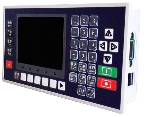
1 TOPCNC TC55V Instruction Manual
2 1. Product Introduction TC55E is an upgrading version of TC55. It is equipped with 3.5 inch color screen, RS 485 communication, Chinese/English Switch, and USB connection. Boot picture can be set as pictures or company name as you will. It is highly reliable, highly accurate, low noise and easy to use. 2. Technical Specifications Minimum data unit mm Maximum data size ± mm Maximum Speed: 9000mm/min (pulse is 0.001mm) Maximum pulse output frequency 150KHz Axis 1-4 (X,Y, Z,C) X,Y,Z,C axis can conduct linear interpolation, X,Y can do circular interpolation. Electric Gear: numerator : denominator: System main functions are automatic, manual, program editing, system parameters, self-check, settings, etc. Maximum 480 commands each program USB Connection and upgrade Stop and Start of Spindle motor PLC Extension I/O Extension Isolated I/O port Self defining of I/O port Chinese/English panel display Free boot picture setting 3. Conversational Programming Code Conversational programming method, automatically lead you to finish programming. 3.1 Programming Function Introduction Programming Code Incremental Absolute Pause Output Repeat Clockwise Counter-clockwise Interpretation Incremental Programming Absolute Programming Pause unless certain condition is met, then skip to command called Define on and off of output port, ex. Stop and start of spindle motor Go back to command called and repeat Clockwise circular interpolation (Incremental programming) Counter Clockwise interpolation(incremental programming)
3 Delay Define the time of delay Judge Judge if certain condition is met and skip to command called Skip Whenever this command is executed, unconditionally skip to command called. Fast Fast positioning Machine Zero Go back to machine zero Speed Axis move at certain speed, and will stop when certain condition met Register When this command is executed, the number on main interface and manual interface will be set to this number. Count When this command is executed, the number on main interface and manual interface will increase by 1 or decrease by 1. Subprog Call Subprogram Called Subprog Start Subprogram Started Subprog End Subprogram Ended Coordinate Set the current position as new coordinates End When the commands can not be read, it will be considered as End. Coordinating This command is similar with Judge, when certain condition of coordinates is met, it will skip to command called. PLC Judge When certain condition of PLC register value is met, it will skip to command called. PLC Set Set Register address and value 3.2 Programming Example Start to program X axis motor first run 10mm, 500mm/min, then output port 1 is connected, then wait for the signal of input port 1, when the signal of input port 1 is detected, output port 1 is off. Main Interface Choose Prog Then choose New A new file is created, with interface showing n 1 End File---- Tab:0 Press to find Incremental Then the interface will be N001 Incremental File---- Tab:0 X:0.000 Y:0.000 Z:0.000 C:0.000 F:0 Move the up and down arrow, to take the cursor go to X, and input 10, then go to F, input 500
4 Press to create n2 command, After finishing all the programming it should be like this: n001 Incremental File----- Tab:0 X:10 Y:0.000 Z:0.000 C:0.000 F:500 n002 Output File---- Tab: 0 OutputPort:1 Status: 1 (this blank can only be filled 1 or 0, change by using ) n003 Paus File---- Tab:0 InputPort:1 Cond:0 LineCall: 0 n004 Output File----- Tab: 0 Oup Pt: 1 Status: 0 n005 End File---- Press or to examine if it is right, then press, then press Save Key Circular Interpolation Left: n1 Incremental X Y 0 n2 Clockwise X Y R-10 Right:n1 Incremental X Y 0 n2 Clockwise X Y R-10
5 Left:n1 Incremental X Y 0 n2 Counter-clockwise X Y R-10 Right:n1 Incremental X Y 0 n2 Counter-clockwise X Y R-10 How to draw a full circle whose diameter is 50mm. n1 Clockwise X100 Y0 R50 n2 Counter-clockwise X-100 Y0 R Parameter Set **Before the setting of parameters, please log in. Par-User-User code Control Parameters Language: Choose English or Chinese External IO: the I/O port number can be extended using TC55-KA(not included in TC55 package) to 30/24. External PLC: PLC TC4616(not included in TC55 package) can be extended. X axis Reference Point: In manual operation, long press 1 to clear the coordinates and show this value; or in machine zero, after hit the switch, it will show this value. X Axis Numerator( ) X Axis Denominator ( ) Y axis Reference Point: In manual operation, long press 2 to clear the coordinates and show this value; or in machine zero, after hit the switch, it will show this value. Y Axis Numerator( ) Y Axis Denominator ( ) Z axis Reference Point: In manual operation, long press 3 to clear the coordinates and show this value; or in machine zero, after hit the switch, it will show this value. Z Axis Numerator( ) Z Axis Denominator ( ) C axis Reference Point: In manual operation, long press 6 to clear the coordinates and show this value; or in machine zero, after hit the switch, it will show this value. C Axis Numerator( ) C Axis Denominator ( ) Spd+Time(ms): time use for motor to reach F speed. Jog+No.(um): in manual operation, increment for jogging. X Gap(um): X axis adjusting gap(to make it more precise) Y Gap(um): Y axis adjusting gap(to make it more precise)
6 Z Gap(um): Z axis adjusting gap(to make it more precise) C Gap(um): C axis adjusting gap(to make it more precise) X ZeroStart: Choose on or off to choose whether the system will first go back to mechanical zero after booting. Y ZeroStart: Choose on or off to choose whether the system will first go back to mechanical zero after booting. Z ZeroStart: Choose on or off to choose whether the system will first go back to mechanical zero after booting. C ZeroStart: Choose on or off to choose whether the system will first go back to mechanical zero after booting. Press enter to choose on or off The following function can only be used when Sell Code logged in Pro Edit: choose hide will make user unable to edit program. ProShow: choose hide will make user unable to see programs TimeLock: after sell code logged in, Para Set-UserMgmt-Sys Veri to set 8digit code to lock the system Setting of Electronic Gear Ratio Setting the electronic gear is to set different data unit for different machines. Different axis of the same machine can be set based on different unit. For example, axis A can be set as mm, axis B can be set as angle, and axis C can be set as round. How to set the numerator and denominator of electronic gear ratio: Pulse needed for the motor to turn one round to the same direction Distance moved when the motor turn one round to the same direction(μm) Numerator and denominator both should be integer between 1 and Ex. 1 Screw Transmission Stepper motor stepping is 5000, or servo motor 5000 pulse/round, screw pitch is 6mm, reduction ratio is 1:1, then, *1000*1.0 6 Ex. 2 Rack and Pinion Stepper motor stepping is 6000, or servo motor 6000 pulse/round, gear teeth number is 20, m=p/π=2, then *20*2*
7 Ex. 3 Rotary Angle Stepper motor stepping is 5000, or servo motor 5000 pulse/round, reduction ratio is 1:30, then, 5000* * Speed Parameters Hsped-X: The highest speed of x axis motor. When the system is operating, speed will not exceed this number no matter what F you set. Hsped-Y: The highest speed of Y axis motor. When the system is operating, speed will not exceed this number no matter what F you set. Hsped-Z: The highest speed of Z axis motor. When the system is operating, speed will not exceed this number no matter what F you set. Hsped-C: The highest speed of C axis motor. When the system is operating, speed will not exceed this number no matter what F you set. StartSpd(mm/min)Speed during Spd+Time Man Hspd:Manual high speed Man Lspd:Manual low speed Jog Spd: Jog speed BZHSpd:Go to machine zero at high speed. BZLSpd:Go back to machine zero first at high speed, through zero switch and move back at low speed. Finally slider will stop on the switch. BZMode:two modes to go back to machine zero, trough switch or not. Through switch: slider will stop on switch. Not trough switch: Slider will stop before the switch. X+ Coor:X axis positive limit coordinates X-Coor:X axis negative limit coordinates Y+ Coor:Y axis positive limit coordinates Y-Coor:Y axis negative limit coordinates Z+Coor:Z axis positive limit coordinates Z-Coor:Z axis negative limit coordinates C+Coor:C axis positive limit coordinates C-Coor:C axis negative limit coordinates 4. Auto Run Auto Run: press this automatically operate programs opened last time.

8 Dry: Press the key and it become negative display, then press Auto Run to start running without load. Step: Positive display means consecutive operation. Negative display means operate command by command. When it is negative display, press Actl Run once, one command will be executed. Stop: Press this to end the program and go back to the first line of the command. 5. Manual Speed: Negative display means manual high speed, positive display means manual low speed. Define manual high speed and manual low speed in Parameters-Speed-Man Hspd/Lspd. Jog: Negative display means jog. Press direction key to jog once. Jog amount is set in Parameters-Control-Jog+No.; Jog speed will be set in Parameters-Speed-Jog Spd Program Zero: Press this key all axis go back to reference point at highest speed. Define the highest speed in Parameters-Speed. Note: Machine Zero Machine zero key is in the panel, press this key, then press direction key of an axis, this axis will go back to machine zero at high speed, after touching the switch, this axis will move at low speed(this machine zero mode is trough switch). Define high speed and low speed of go back to machine zero in Parameters-Speed. Define machine zero in I/O-System. Press key 1 to return X axis coordinates to reference point, Press key 3 to return Y axis coordinates to reference point, Press key 3 to return Z axis coordinates to reference point, Press key 6 to return C axis coordinates to reference point. Define reference point in Parameters-Control. Define the mode of going back to machine zero in Parameters-Speed-BZMode. 6. Installation Size
9 Reference 1 Wiring Definition XP+ X axis pulse positive output X Axis XP- X axis pulse negative output XD+ X axis direction positive output XD- X axis direction negative output YP+ Y axis pulse positive output Y Axis YP - Y axis pulse negative output YD+ Y axis direction positive output YD- Y axis direction negative output ZP+ Z axis pulse positive output Z Axis ZP - Z axis pulse negative output ZD+ Z axis direction positive output ZD- Z axis direction negative output CP+ C axis pulse positive output C Axis CP- C axis pulse negative output CD+ C axis direction positive output CD- C axis direction negative output Output 01~08 Output 01-08,Connect to power 24V+ through Relay or solenoid valve Input 01~16 Connect to power 24V- through machine or switch 485 R+ 485 connect DATA+ R- 485 connect DATA- System Power 24V System Power Supply+ 0V System Power Supply- IO Power V I/O Power Supply+ G I/O Power Supply- USB Downloading Port Encoder Used to make special machine controller (This controller do not support encoder unless customer specially said they need it) I/O Extension Connect to I/O extension connection
10 1. Connect with servo or stepper driver 2. Connect with PLC 3. Connect with Power Supply
11 4. Connection Layout
12 Reference 2 I/O Port 1. System Set This function unable user to set various kind of switch easily. Define the I/O port according following form. Press I/O key on the panel to enter this interface. Functions Interpretation Methods X Axis Lim+ X axis Positive limit setting External Big switch is needed to finish X Axis Lim- Y Axis Lim+ Y Axis Lim- Z Axis Lim+ Z Axis Lim- C Axis Lim+ C Axis Lim- AlerInpu EmStInpu X 0 Y 0 Z 0 C 0 OutStart X axis Negative limit setting Y axis Positive limit setting Y axis Negative limit setting Z axis Positive limit setting Z axis Negative limit setting C axis Positive limit setting C axis Negative limit setting Alert Input Emergency Stop Input X axis zero switch setting Y axis zero switch setting Z axis zero switch setting C axis zero switch setting Outside(External) Start Switch Setting external control. External switch is connected in the way of normal open. Press Shift to change off into on, and choose N.O.(Normal Open). Then choose the IO Port number. Note: For safety consideration, limit and emergency stop input is usually set as N.C.(Normal Close). Out EmSt Outside(External) Emergency Stop Setting Spd+Inpu Spd-Inpu Speed Increase Outside Switch Speed Decrease Outside Switch OutPt 1-8 External input port control output port 2. Jog Set This function is normally used in manual adjusting parameters of machine to reach a optimal situation. Functions Interpretation Methods Man X+ X axis clockwise spinning outside manual Choose on or off switch Choose N(Negative) or Man X- X axis counter clockwise spinning outside manual switch P(Positive) X HSup X axis high speed up
13 X HSdown X LSup X LSdown Man Y+ Man Y- Y HSup Y HSdown Y LSup Y LSdown Man Z+ Man Z- Z HSup Z HSdown Z LSup Z LSdown Man C+ Man C- C HSup C HSdown C LSup C LSdown X ZeroSt Y ZeroSt Z ZeroSt C ZeroSt Auto UI Manual UI Prog Zero X axis high speed down X axis low speed up X axis low speed down Y axis clockwise spinning outside manual switch Y axis counter clockwise spinning outside manual switch Y axis high speed up Y axis high speed down Y axis low speed up Y axis low speed down Z axis clockwise spinning outside manual switch Z axis counter clockwise spinning outside manual switch Z axis high speed up Z axis high speed down Z axis low speed up Z axis low speed down C axis clockwise spinning outside manual switch C axis counter clockwise spinning outside manual switch C axis high speed up C axis high speed down C axis low speed up C axis low speed down X axis Machine zero external manual switch Y axis Machine zero external manual switch Z axis Machine zero external manual switch C axis Machine zero external manual switch Auto operation UI Manual operation UI All axis go back to Program zero
TOPCNC TC55V Instruction Manual
 TOPCNC TC55V Instruction Manual 1. Product Introduction TC55E is an upgrading version of TC55. It is equipped with 3.5 inch color screen, RS 485 communication, Chinese/English Switch, and USB connection.
TC55 New Version. INSTRUCTION MANUAL. Contacts:
 Contacts: Moscow +7 (495) 505 63 74 Voronezh +7 (473) 204 51 56 149 Office 160, Leninsky avenue Voronezh, Russia, 394033 Monday - Thursday: 8.00 17:00 Friday: 8.00 16.00 Break: 12.30 13.30 sales@purelogic.ru
Drive Control Instructions
 Drive Control Instructions DRV: High Speed Positioning 16Bits Instruction: -- 32 Bits Instruction: Below Suitable Model: Function & Action X axis and Y axis high speed positioning with the maximum speed:
0501 Users Guide. Chapter I Characteristic
 0501 Users Guide Chapter I Characteristic 1. Totally independent from PC platform; 2. Directly read files from U Disk; 3. Easily process G code or PLT file with super size; 4. Strong system and process
SC125MS. Data Sheet and Instruction Manual. ! Warning! Salem Controls Inc. Stepper Motor Driver. Last Updated 12/14/2004
 SC125MS Stepper Motor Driver Salem Controls Inc. Last Updated 12/14/2004! Warning! Stepper motors and drivers use high current and voltages capable of causing severe injury. Do not operate this product
GE Fanuc Automation. Alpha i Series AC Servo Motor. Computer Numerical Control Products. Parameter Manual
 GE Fanuc Automation Computer Numerical Control Products Alpha i Series AC Servo Motor Parameter Manual GFZ-65270EN/01 May 2001 Warnings, Cautions, and Notes as Used in this Publication GFL-001 Warning
Magnetic Fields. Experiment 1. Magnetic Field of a Straight Current-Carrying Conductor
 General Physics Lab Department of PHYSICS YONSEI University Lab Manual (Lite) Magnetic Fields Ver.20181029 NOTICE This LITE version of manual includes only experimental procedures for easier reading on
Hands-on Lab 3. System Identification with Experimentally Acquired Data
 Hands-on Lab 3 System Identification with Experimentally Acquired Data Recall that the course objective is to control the angle, rise time and overshoot of a suspended motor-prop. Towards this, the two
Rotary modules.
 Rotary modules www.comoso.com www.comoso.com Rotary modules ROTARY MODULES Series Size Page Rotary modules RM swivel unit 156 RM 08 160 RM 10 162 RM 12 164 RM 15 168 RM 21 172 RM rotor 176 RM 50 180 RM
BOXED BEAM ROLL FORMING MACHINE
 BOXED BEAM ROLL FORMING MACHINE R O L L F O R M E R S U S A I W W W. R O L L F O R M E R S - U S A. C O M Page1 R O L L F O R M E R S U S A I W W W. R O L L F O R M E R S - U S A. C O M Page2 Cantilevered
Standard specifications ZX165UFE02001
 Standard specifications ZXUF000 May, 0 KAWASAKI HAVY INDUSTRIS, LTD. ROBOT DIVISION Materials and specifications are subject to change without notice. Specification : (Arm): (Controller): 00-DA 0-00DA
Motors Automation Energy Transmission & Distribution Coatings. Servo Drive SCA06 V1.5X. Addendum to the Programming Manual SCA06 V1.
 Motors Automation Energy Transmission & Distribution Coatings Servo Drive SCA06 V1.5X SCA06 V1.4X Series: SCA06 Language: English Document Number: 10003604017 / 01 Software Version: V1.5X Publication Date:
Lightcloud Application
 Controlling Your Lightcloud System Lightcloud Application Lightcloud Application Navigating the Application Devices Device Settings Organize Control Energy Scenes Schedules Demand Response Power Up State
STUD & TRACK ROLL FORMING MACHINE
 STUD & TRACK ROLL FORMING MACHINE R O L L F O R M E R S U S A I W W W. R O L L F O R M E R S - U S A. C O M Page1 Cantilevered Dual Headed 6,000 lb Decoiler Includes mandrel and stand Can accommodate 22
S Sapling INSTALLATION MANUAL FOR FIELD SELECTABLE ANALOG CLOCKS SAA SERIES SPECIFICATIONS. advanced time and control systems
 INSTALLATION MANUAL FOR FIELD SELECTABLE ANALOG CLOCKS SAA SERIES SPECIFICATIONS Time base: 60 Hz (3-wire system) Quartz (2-wire system) Power input: 85 135 VAC / 60 Hz 7 28 VAC / 60 Hz Current consumption:
SuperCELL Data Programmer and ACTiSys IR Programmer User s Guide
 SuperCELL Data Programmer and ACTiSys IR Programmer User s Guide This page is intentionally left blank. SuperCELL Data Programmer and ACTiSys IR Programmer User s Guide The ACTiSys IR Programmer and SuperCELL
Sample Alignment Part
 Sample Alignment Part Contents Contents 1. How to set Part conditions...1 1.1 Setting conditions... 1 1.2 Customizing scan conditions and slit conditions... 6 2. Sample alignment sequence...13 2.1 Direct
Lab 3: Quanser Hardware and Proportional Control
 Lab 3: Quanser Hardware and Proportional Control The worst wheel of the cart makes the most noise. Benjamin Franklin 1 Objectives The goal of this lab is to: 1. familiarize you with Quanser s QuaRC tools
Ocean Optics Red Tide UV-VIS Spectrometer (Order Code: SPRT-UV-VIS)
") Ocean Optics Red Tide UV-VIS Spectrometer (Order Code: SPRT-UV-VIS) The UV-VIS spectrometer is a portable ultraviolet light and visible light spectrophotometer, combining a spectrometer and a light source/cuvette
Ocean Optics Red Tide UV-VIS Spectrometer (Order Code: SPRT-UV-VIS) The UV-VIS spectrometer is a portable ultraviolet light and visible light spectrophotometer, combining a spectrometer and a light source/cuvette
AKD SYSTEM CONFIGURATION WITH KOLLMORGEN DDL LINEAR MOTORS By Kenny Hampton 1/12/2017 Rev. L
 AKD SYSTEM CONFIGURATION WITH KOLLMORGEN DDL LINEAR MOTORS By Kenny Hampton 1/12/2017 Rev. L This document shows the wiring requirements for connecting the DDL linear motors to the AKD servo drive. It
Lasentec Product Group
 Document Number: 004-0043 Window Reference Procedure - M500/600 P Probes, version 6.0 and higher FBRM CI Software The Window Reference Procedure is the standard calibration procedure used to reference
MEM-BUS ABSOLUTE ENCODER
 MEM-BUS ABSOLUTE ENCODER With PROFINET Interface Application Examples Software version STEP7 CONTENTS Applications with ELAP encoder... 3 Example 1: Angle position measurement on a rotary table with mechanical
Acceleration/Velocity/Displacement VIBRATION METER
 Acceleration/Velocity/Displacement VIBRATION METER Model : VB-8220 Your purchase of this VIBRATION METER marks a step forward for you into the field of precision measurement. Although this METER is a complex
HMS-5000 Manual. Product Name: HMS-5000 Hall Effect Measurement System with variable temperature from 80K to 350K. - Manual version: ver 5.
 HMS-5000 Manual Product Name: HMS-5000 Hall Effect Measurement System with variable temperature from 80K to 350K - Manual version: ver 5.01- www.ecopia21.co.kr - Table of contents - 1. Hardware Installation
GE Fanuc Automation. Alpha Series AC Servo Motor. Computer Numerical Control Products. Parameter Manual
 GE Fanuc Automation Computer Numerical Control Products Alpha Series AC Servo Motor Parameter Manual GFZ-65150E/04 December 1999 Warnings, Cautions, and Notes as Used in this Publication GFL-001 Warning
the foundation of any business starts here
 the foundation of any business starts here TABLE OF CONTENT The Company... 3 Electric Motors... 4 Gearboxes... 5 Automation Products... 6 Electric Components... 9 Pneumatics... 12 Hydraulics... 13 Handling
R I T. Title: GCA Stepper Operations. Semiconductor & Microsystems Fabrication Laboratory Revision: F Rev Date: 08/09/ SCOPE
 Approved by: Process Engineer / / / / Equipment Engineer 1 SCOPE The purpose of this document is to detail the use of the GCA Stepper. All users are expected to have read and understood this document.
Haas trunnions have more than one configuration. Thus, to make a program for the trunnion, you must know these facts:
 Haas Technical Documentation Trunnion Information Scan code to get the latest version of this document Translation Available Trunnion Features Haas trunnions have more than one configuration. Thus, to
MODEL: CNC-C600 PRODUCT SPECIFICATION
 茗亞精密機械股份有限公司 NEUAR PRECISION MACHINERY COMPANY LTD. No. 11, Aly. 19, Ln. 20, Daxing Rd., Luzhu Dist., Taoyuan City, Taiwan Tel:886-3-3136986 ; Fax:886-3-3232376 E-mail: neuar.edm@msa.hinet.net ; Website:
ISSP User Guide CY3207ISSP. Revision C
 CY3207ISSP ISSP User Guide Revision C Cypress Semiconductor 198 Champion Court San Jose, CA 95134-1709 Phone (USA): 800.858.1810 Phone (Intnl): 408.943.2600 http://www.cypress.com Copyrights Copyrights
Quick Start Guide New Mountain Visit our Website to Register Your Copy (weatherview32.com)
") Quick Start Guide New Mountain Visit our Website to Register Your Copy (weatherview32.com) Page 1 For the best results follow all of the instructions on the following pages to quickly access real-time
Quick Start Guide New Mountain Visit our Website to Register Your Copy (weatherview32.com) Page 1 For the best results follow all of the instructions on the following pages to quickly access real-time
POINTS OF CAUTION BEFORE USE...
 INSTRUCTION MANUAL NPN DISCRETE INPUT & NPN TRANSISTOR OUTPUT MODULE, 6 points each (-I/-II, e-con connector) MODEL BEFORE USE... Thank you for choosing M-System. Before use, check the contents of the
FAGOR 8055 CNC Ordering Handbook. Ref. 1502
 FAGOR 8055 CNC Ordering Handbook. Ref. 1502 FAGOR AUTOMATION Fagor 8055 CNC - Ordering Handbook - Ref. 1502 pg. 1 / 10 DENOMINATIONS UC55 - - - - - - - - - - Type of CNC (CNC 8055 Central Unit) CPU type
Technical Guide for Servo Motor Selection
 Technical Guide for Servo otor Selection CS_Servo Selection_TG_E_3_1 Servo otor Selection Software Use your PC to select a Servo otor "otor Selection Program for Windows" o you always feel "Calculation
Quick Start Guide. The ieq45 GoTo German Equatorial Mount # 8000C
 Quick Start Guide The ieq45 GoTo German Equatorial Mount # 8000C PACKAGE CONTENTS Telescope Mount (with built-in GPS) 3.5 Vixen type dovetail saddle (installed on the mount) 8 Losmandy-D type dovetail
Double Inverted Pendulum (DBIP)
") Linear Motion Servo Plant: IP01_2 Linear Experiment #15: LQR Control Double Inverted Pendulum (DBIP) All of Quanser s systems have an inherent open architecture design. It should be noted that the following
Linear Motion Servo Plant: IP01_2 Linear Experiment #15: LQR Control Double Inverted Pendulum (DBIP) All of Quanser s systems have an inherent open architecture design. It should be noted that the following
Laboratory Exercise #11 A Simple Digital Combination Lock
 Laboratory Exercise #11 A Simple Digital Combination Lock ECEN 248: Introduction to Digital Design Department of Electrical and Computer Engineering Texas A&M University 2 Laboratory Exercise #11 1 Introduction
Acceleration, Velocity, Separate probe VIBRATION METER Model : VB-8202
 Acceleration, Velocity, Separate probe VIBRATION METER Model : VB-8202 Your purchase of this VIBRATION METER marks a step forward for you into the field of precision measurement. Although this METER is
MODEL: CNC-HC60Q PRODUCT SPECIFICATION
 茗亞精密機械股份有限公司 NEUAR PRECISION MACHINERY COMPANY LTD. No. 11, Aly. 19, Ln. 20, Daxing Rd., Luzhu Dist., Taoyuan City 338, Taiwan, R. O. C Tel:886-3-3136986 ; Fax:886-3-3232376 E-mail: neuar.edm@msa.hinet.net
SimpleDreamEQ2. Upgrade kit equatorial mounts Synta EQ2, Celestron CG3. User guide. Micro GoTo system. Micro GoTo system
 SimpleDreamEQ2 Upgrade kit equatorial mounts Synta EQ2, Celestron CG3 User guide Micro GoTo system Micro GoTo system AstroGadget 2017 1. DESCRIPTION The kit consists of a control unit and a set of drives
Operation Manual. SPECTRO-NANO4 Nucleic Acid Analyzer PLEASE READ THIS MANUAL CAREFULLY BEFORE OPERATION
 Operation Manual SPECTRO-NANO4 Nucleic Acid Analyzer PLEASE READ THIS MANUAL CAREFULLY BEFORE OPERATION 3, Hagavish st. Israel 58817 Tel: 972 3 5595252, Fax: 972 3 5594529 mrc@mrclab.com MRC. 4.18 Foreword
473-SHX Dew Point Mirror
 Humidity and Temperature Reference Hygrometer For Temperature up to 125 C Precise and stable chilled mirror dew point mirror technology High temperature optical components High temperature sample fan Cable
Software BioScout-Calibrator June 2013
 SARAD GmbH BioScout -Calibrator 1 Manual Software BioScout-Calibrator June 2013 SARAD GmbH Tel.: ++49 (0)351 / 6580712 Wiesbadener Straße 10 FAX: ++49 (0)351 / 6580718 D-01159 Dresden email: support@sarad.de
OPERATING MANUAL. EIB-Kombisensor AS 315 N
 EIB-Kombisensor AS 315 N OPERATING MANUAL EIB-Kombisensor AS 315 N 1 Contents Page 3 1. Description 4 1.1 Automated Operations 1.1.1 Sun System 1.1.2 Half-Light System 5 1.1.3 Wind System 1.1.4 Rain System
MECH 1500 Final Part 2 Review
 Name: Class: Date: MECH 1500 Final Part 2 Review True/False Indicate whether the statement is true or false. 1. Programmed counters can serve the same function as mechanical counters. 2. Every PLC model
VIBRATION METER Acceleration & Velocity Model : VB-8201HA
 VIBRATION METER Acceleration & Velocity Model : VB-8201HA TABLE OF CONTENTS 1. FEATURES... 1 2. SPECIFICATIONS...2 3. FRONT PANEL DESCRIPTION...4 3-1 Display...4 3-2 BNC socket of meter...4 3-3 RMS/PEAK
Acceleration and velocity are related and have a direct impact on the three basic parts of the CNC system.
 Acceleration and velocity are related and have a direct impact on the three basic parts of the CNC system. ACCELERATION Acceleration is a change in velocity with respect to time. The term, in context of
ON SITE SYSTEMS Chemical Safety Assistant
 ON SITE SYSTEMS Chemical Safety Assistant CS ASSISTANT WEB USERS MANUAL On Site Systems 23 N. Gore Ave. Suite 200 St. Louis, MO 63119 Phone 314-963-9934 Fax 314-963-9281 Table of Contents INTRODUCTION
Inverted Pendulum System
 Introduction Inverted Pendulum System This lab experiment consists of two experimental procedures, each with sub parts. Experiment 1 is used to determine the system parameters needed to implement a controller.
EUROMASTER HYDRAULIC PRESSBRAKES
 EUROMASTER HYDRAULIC PRESSBRAKES EUROMASTER HYDRAULIC PRESSBRAKES 02_ EUROMASTER Euromaster 50250 The Euromaster has been developed as a modern pressbrake with electronic levelling and depth control Synchro
Date: Summer Stem Section:
 Page 1 of 7 Name: Date: Summer Stem Section: Summer assignment: Build a Molecule Computer Simulation Learning Goals: 1. Students can describe the difference between a molecule name and chemical formula.
10 - Celestron Telescope II: Operation
 10 - Celestron Telescope II: Operation Purpose: Gain more experience setting up a 6 Celestron telescope, familiarize yourself with the software interface, and acquire an image with the CCD camera. Due:
CALIFORNIA STATE UNIVERSITY, BAKERSFIELD (CSUB) Laboratory 3
 Laboratory 3") ALIFORNIA STATE UNIERSITY, BAKERSFIELD (SUB) DEPARTMENT OF ELETRIAL & OMPUTER ENGINEERING & OMPUTER SIENE EE 3320: FIELDS AND WAES Laboratory 3 First, get familiar with the oscilloscope It is a powerful
ALIFORNIA STATE UNIERSITY, BAKERSFIELD (SUB) DEPARTMENT OF ELETRIAL & OMPUTER ENGINEERING & OMPUTER SIENE EE 3320: FIELDS AND WAES Laboratory 3 First, get familiar with the oscilloscope It is a powerful
Non-Acoustical Inputs
 CHAPTER 18 Non-Acoustical Inputs This chapter discusses the use of external transducers and devices to provide non-acoustical data to the Model 831. Included are the following: 831-INT 831-INT Interface
рн PRO Controller The device is used to control and regulate ph level in hydroponic systems and water preparing units automatically USER MANUAL
 рн PRO Controller The device is used to control and regulate ph level in hydroponic systems and water preparing units automatically Complete Set ph PRO Controller - 1 pcs. ph electrode - 1 pcs. Calibration
PC Control / Touch Control
 PC Control / Touch Control Version 6.0 / 5.840.0150 New Features Manual 8.840.8007EN Metrohm AG CH-9101 Herisau Switzerland Phone +41 71 353 85 85 Fax +41 71 353 89 01 info@metrohm.com www.metrohm.com
Minute Impulse Clock Controller I01DN
 99b-mi USER S MANUAL Minute Impulse Clock Controller Mon Jun 01, 2009 12:00:00 PM DST HOLD ENTER KEY TO BEGIN CANCEL HR I01DN 97 West Street Medfield, MA 02052 U.S.A. (508) 359-4396 Pg. 2 of 20 TABLE OF
MULTIFUNCTION COMPUTER METER CX-742 USERS MANUAL
 MULTIFUNCTION COMPUTER METER CX-742 USERS MANUAL CONTENTS 1. BASIC INFORMATION 3 2. USING THE INFORMATION 4 3. THE PROFILE OF THE METER 5 4. TECHNICAL DATA 7 5. SCREENS 8 6. USING THE KEYBOARD 10 7. THE
BEFORE USE... POINTS OF CAUTION COMPONENT IDENTIFICATION INSTRUCTION MANUAL MODEL R7K4DH-1-DAC32D R7K4DH-1-DAC32D
 INSTRUCTION MANUAL PNP DISCRETE INPUT & PNP TRANSISTOR OUTPUT MODULE, 6 points each (High-speed Link System, e-con connector) R7KDH--DACD MODEL R7KDH--DACD BEFORE USE... Thank you for choosing M-System.
Sample Alignment (2D detector) Part
 Part") Sample Alignment (2D detector) Part Contents Contents 1 How to set Part conditions...1 1.1 Setting conditions... 1 1.2 Customizing scan conditions and slit conditions... 6 2 Sample alignment sequence...13
Sample Alignment (2D detector) Part Contents Contents 1 How to set Part conditions...1 1.1 Setting conditions... 1 1.2 Customizing scan conditions and slit conditions... 6 2 Sample alignment sequence...13
Flexitest Switch Assemblies Type FT-19R and FT-19RX Supersedes DB March 2008
 Flexitest Switch Assemblies Type FT-19R and FT-19RX Supersedes DB41-078 March 2008 FT-19R and FT-19RX FT-19R 3RU with Individual Clear Covers APPLICATION FEATURES The type FT-19R (standard length) and
Servo Motor Selection Flow Chart
 Servo otor Selection Flow Chart START Selection Has the machine Been Selected? YES NO Explanation etermine the size, mass, coefficient of References friction, and external forces of all the moving part
Quartz Crystal Nanobalance (QCN)
") Quartz Crystal Nanobalance (QCN) Introduction Quartz crystal micro/nanobalance (QCM/QCN) is a very sensitive instrument used to measure the mass changes on an electrode surface. A QCN can detect mass changes
Quartz Crystal Nanobalance (QCN) Introduction Quartz crystal micro/nanobalance (QCM/QCN) is a very sensitive instrument used to measure the mass changes on an electrode surface. A QCN can detect mass changes
water work RAIN BUCKET making since 1986 ET2000 (500 SERIES) RAIN BUCKET SETUP
 RAIN BUCKET SETUP") RAIN BUCKET SETUP RAIN BUCKET ET2000 (500 SERIES) RAIN BUCKET SETUP 8 8 4 3 2 5 6 7 1 10 9 1 STOP The STOP key will stop any currently running Scheduled watering Cycle, Manual Cycle, Test Cycle. 2 MANUAL
RAIN BUCKET SETUP RAIN BUCKET ET2000 (500 SERIES) RAIN BUCKET SETUP 8 8 4 3 2 5 6 7 1 10 9 1 STOP The STOP key will stop any currently running Scheduled watering Cycle, Manual Cycle, Test Cycle. 2 MANUAL
Atomic and nuclear physics
 Atomic and nuclear physics X-ray physics Physics of the atomic shell LEYBOLD Physics Leaflets Moseley s law and determination of the Rydberg constant P6.3.3.6 Objects of the experiment Measuring the K-absorption
Free fall with an interface system
 Related topics Motion along a straight line subject to constant acceleration, laws governing falling bodies, acceleration due to gravity. Principle and task The fall times t are measured for different
O P E R A T I N G M A N U A L
 OPERATING MANUAL WeatherJack OPERATING MANUAL 1-800-645-1061 The baud rate is 2400 ( 8 bits, 1 stop bit, no parity. Flow control = none) To make sure the unit is on line, send an X. the machine will respond
An NC program is a program that defines the entire sequence of a machining operation to be carried out on a particular CNC machine tool:
 Outline MC Programming I NC Program NC Codes Blocks G and M codes Other codes Programming Basic Motions Rapid travel Linear motion Circular motion Examples NC Program An NC program is a program that defines
ACE Control System. 1.0-m Pomona College Telescope Table Mountain Observatory ACE User Manual April 2005 Revision All rights reserved.
 ACE Control System 1.0-m Pomona College Telescope Table Mountain Observatory ACE User Manual April 2005 Revision 1.1 1999-2005. All rights reserved. Astronomical Consultants & Equipment, Inc. P.O. Box
NR ROTARY RING TABLE: FLEXIBLE IN EVERY RESPECT
 NR FREELY PROGRAMMABLE ROTARY TABLES NR ROTARY RING TABLE All NR rings allow customer-specific drive motors to be connected NR ROTARY RING TABLE: FLEXIBLE IN EVERY RESPECT WHEN IT S GOT TO BE EXACT We
Synchronous Sequential Circuit Design. Dr. Ehab A. H. AL-Hialy Page 1
 Synchronous Sequential Circuit Design Dr. Ehab A. H. AL-Hialy Page Motivation Analysis of a few simple circuits Generalizes to Synchronous Sequential Circuits (SSC) Outputs are Function of State (and Inputs)
Coating K = TFE wear resist, dry lubricant Kerkote X = Special coating, (Example: Kerkote with grease)
") HAYD: 0 WGS0 Low Profile, Screw Driven Slide WGS0 Linear Rail with Hybrid 000 Series Size Single and Double Stacks and 000 Series Size Single and Double Stacks Kerk Motorized WGS Linear Slide utilizes
HAYD: 0 WGS0 Low Profile, Screw Driven Slide WGS0 Linear Rail with Hybrid 000 Series Size Single and Double Stacks and 000 Series Size Single and Double Stacks Kerk Motorized WGS Linear Slide utilizes
HMS-5000 Manual. Product Name: HMS-5000 Hall Effect Measurement System with variable temperature from 80K to 350K. - Manual version: ver 5.
 HMS-5000 Manual Product Name: HMS-5000 Hall Effect Measurement System with variable temperature from 80K to 350K - Manual version: ver 5.01- www.ecopia21.co.kr - Table of contents - 1. Hardware Installation
Single cam type. Double cam type. Grip force N. Type Model/size Stroke Screw type straight style. Screw type tee style
 Type Model/size Stroke -SS-0-N. -SS-0-N. Single cam type -SS- 7. -SS-. -SS-4. -SD-0 Double cam type -SD- -SD-4. Screw type straight style Screw type tee style -FS- -FT- -FS- -FT- 0.9 1. 1.. 1. 4 Grip forcen
Caution! Pay close attention to the special operation and safety instructions in the manual of the ultrasonic echoscope.
 Ultrasonic B-Scan TEAS Related topics Sound velocity, reflection coefficient, ultrasonic echography, A-scan, B-scan, grey-scale dis-play, resolution, zone of focus, and image artefacts. Principle The fundamental
Ramberg-Osgood Convertor. User Manual
 Ramberg-Osgood Convertor User Manual For Version: 1.0.5 Copyright 2010-2016 OPIMsoft Technology Co., Ltd. All Rights Reserved. INDEX 1 FUNCTION... 1 2 INSTALLATION... 4 3 HOW TO USE... 5 4 THEORY INSTRUCTION...
ST - DS - Toolholders to the Spindle Centerline - Correction
 LAST UPDATED: 11/28/2018 Page 1 of 9 pages Toolholders to the Spindle Centerline - Correction Page 2 of 9 pages This section tells you how to align the toolholders [1] to the spindle centerline [2]. 1
www. ElectricalPartManuals. com Flexitest Switch Assemblies Type FT-19R and FT-19RX INTL APPLICATION
 Effective: January 2004 Supersedes, dated June 1998 APPLICATION QUALITY FEATURES Descriptive Bulletin 41-078INTL Flexitest Switch Assemblies Type The type FT-19R (standard length) and FT-19RX (extended
Design at the Register Transfer Level
 Week-7 Design at the Register Transfer Level Algorithmic State Machines Algorithmic State Machine (ASM) q Our design methodologies do not scale well to real-world problems. q 232 - Logic Design / Algorithmic
xlogic SuperRelay is a compact and expandable CPU replacing mini PLCs, multiple timers, relays and counters.
 SuperRelay S U P E R R E L A Y, T H E P E R F E C T A L T E R N A T I V E T O L O W C O S T P L C s A N D B A S I C R E L A Y S I N T H I S B R O C H U R E : ELC 18 Standard Models ELC 18 Economy Models
Digital Land Surveying And Mapping(DLS&M) Dr. Jayanta Kumar Ghosh Department of Civil Engineering Indian Institute of Technology, Roorkee
 Dr. Jayanta Kumar Ghosh Department of Civil Engineering Indian Institute of Technology, Roorkee") Digital Land Surveying And Mapping(DLS&M) Dr. Jayanta Kumar Ghosh Department of Civil Engineering Indian Institute of Technology, Roorkee Lecture - 17 Total Station Introduction Welcome students, this
Digital Land Surveying And Mapping(DLS&M) Dr. Jayanta Kumar Ghosh Department of Civil Engineering Indian Institute of Technology, Roorkee Lecture - 17 Total Station Introduction Welcome students, this
Rain Watch TM Set up Manual. IC System with Rain Bird IC CONNECT
 Rain Watch TM Set up Manual IC System with Rain Bird IC CONNECT December 2018 Table of Contents Required materials to configure Rain Watch TM... 3 Installation... 4 Location... 4 Field Installation...
APPENDIX. SELECTING THE SureServo SERVO SYSTEM. In This Appendix... Selecting the SureServo Servo System...B 2. Leadscrew - Example Calculations...
 SELECTING THE SureServo SERVO SYSTEM APPENDIX B In This Appendix... Selecting the SureServo Servo System............B 2 The Selection Procedure......................................B 2 How many pulses
Week 14 The Simple Pendulum
 Week 14 The Simple Pendulum 1. Scope 1.1 Goal Conduct experiment to study the simple harmonic motion of an oscillatory pendulum and analyze and interpret the data 1.2 Units of measurement to use United
C2A for Pulsar2 how to control your telescope from C2A
 C2A for Pulsar2 how to control your telescope from C2A C2a is a free and powerful planetarium program available from.http://www.astrosurf.com/c2a/english/ that offers native support for Pulsar2 without
FAGOR 8055i CNC Ordering Handbook. Ref. 1502
 FAGOR 8055i CNC Ordering Handbook. Ref. 1502 FAGOR AUTOMATION DENOMINATIONS CN55i - - - - - - - Type of CNC (CNC 8055i) CPU type Type of function General purpose Milling machines & Centers Conversational
FRENIC-Ace (C2) (Supplement to RS-485 User's Manual)
 (Supplement to RS-485 User's Manual)") (Supplement to RS-485 User's Manual) FRENIC-Ace (C2) This document is a supplement to the RS-485 Communication User s Manual (24A7-E-0082, MEH448), and is comprised of section 5.2 (Data ), to which content
(Supplement to RS-485 User's Manual) FRENIC-Ace (C2) This document is a supplement to the RS-485 Communication User s Manual (24A7-E-0082, MEH448), and is comprised of section 5.2 (Data ), to which content
Rectilinear System. Introduction. Hardware
 Rectilinear System Introduction For this lab, there are three separate experiments that will be performed. The first experiment will calculate all the system parameters that will be used in later parts
(Cat. No CFM) Product Data
 Product Data") (Cat. No. 1771-CFM) Product Data The CFM module interfaces Allen-Bradley programmable logic controllers (PLCs ) with magnetic pickups, single-channel shaft encoders, turbine flowmeters or any source of
(Cat. No. 1771-CFM) Product Data The CFM module interfaces Allen-Bradley programmable logic controllers (PLCs ) with magnetic pickups, single-channel shaft encoders, turbine flowmeters or any source of
Circular Motion and Centripetal Force
 [For International Campus Lab ONLY] Objective Measure the centripetal force with the radius, mass, and speed of a particle in uniform circular motion. Theory ----------------------------- Reference --------------------------
Calibration Routine. Store in HDD. Switch "Program Control" Ref 1/ Ref 2 Manual Automatic
 4.2 IMPLEMENTATION LABVIEW 4.2.1 LabVIEW features LabVIEW (short for Laboratory Virtual Instrument Engineering Workbench) originally released for the Apple Macintosh in 1986. It is a highly productive
Quick Start and Troubleshooting Guide
 Quick Start and Troubleshooting Guide By RXDesign Copyright July 2003 Quick Start and Troubleshooting Guide Rev 2 Welcome... tto tthe worrl ld off tthe CAT. 1 Addendum - Quick Start Alright... it is installed!
Technical Description
 Overview It is being digitalized and accelerated with builtin micro processor because of development of computer. It is widely used in industrial NC, ROBOT, servo motors and OA equipment in order to detect
UNIWERSAŁ observatory dome
 -see the best with us- UNIWERSAŁ observatory dome sofware manual UNIWERSAŁ the oldest and best known manufacturer of top-quality astronomy and optical equipment in Poland System requirements : - windows
Cosmic Ray Detector Software
 Cosmic Ray Detector Software Studying cosmic rays has never been easier Matthew Jones Purdue University 2012 QuarkNet Summer Workshop 1 Brief History First cosmic ray detector built at Purdue in about
Space Objects. Section. When you finish this section, you should understand the following:
 GOLDMC02_132283433X 8/24/06 2:21 PM Page 97 Section 2 Space Objects When you finish this section, you should understand the following: How to create a 2D Space Object and label it with a Space Tag. How
Tile Pro Drainage Plow Instruction Manual Wayne s Inc.
 Tile Pro Drainage Plow Instruction Manual Wayne s Inc. TILE PRO WITH UPPER HYDRAULIC LINKAGE NORMAL USAGE Notice: Do not operate the upper cylinders when the 4 ½ x 36 lift cylinders are in the lift or
TECDIS and TELchart ECS Weather Overlay Guide
 1 of 24 TECDIS and TELchart ECS provides a very advanced weather overlay feature, using top quality commercial maritime weather forecast data available as a subscription service from Jeppesen Marine. The
Remote Display Unit. Installers Handbook Copyright 2001 AirSense Technology Ltd. LM Remote Display Unit Installers Handbook Issue 1.
 Remote Display Unit Installers Handbook Copyright 2001 AirSense Technology Ltd AirSense, ClassiFire, FastLearn PipeCAD, SenseNET, Stratos-HSSD and Stratos-Quadra are trademarks. HSSD is a Registered Trademark.
Centripetal and centrifugal force
 Introduction In the everyday language use, the centrifugal force is often referred to as the cause of the occurring force during a uniform non-linear motion. Situated in a moving object that changes its