Limit State Design of Steel Pin Connections for Bamboo Truss Structures
|
|
|
- Lynn Clark
- 5 years ago
- Views:
Transcription
1 Limit State Design of Steel Pin Connections for Bamboo Truss Structures Luís Eustáquio Moreira 1,a, Khosrow Ghavami 2,b 1 Federal University of Minas Gerais, Structures Department, Brazil 2 Pontifical Catholic University of Rio de Janeiro, RJ, Brazil a luis@dees.ufmg.br, b ghavami@puc-rio.br Keywords: bamboo, pin connections, mechanical tests, limit diagram Abstract. One of the most important parts of any structure, independent of the material used, is the joint of its elements. In the steel pin connections used in bamboo tubes to assemble truss structures, stress concentration occurs at the contact point between steel pin and bamboo. The stress concentration causes local crushing and cracking along the fibers. Bamboo is a Functionally Graded Material (FGM), which consists of a composite anatomical structure divided in three different microstructures: - sieve vessels surrounded by strong high resistance longitudinal fibers stretching along de culm, both inner the aired parenchyma tissue with its hollow cells. This aligned anatomy could contribute to initiate small cracks close to the contact area between the steel pin and hole. This is due to the combined action of the shear along and the tension perpendicular to the fibers. These cracks oriented in the direction of the fibers could propagate or not, according to the stress fields in the neighborhood of the contact area and along the possible crack path. In cases where two steel pins are used, the optimum space between them and between the first pin and bamboo board should be established. If the axial forces between connected bars do not converge exactly to the same point, the local eccentricities cause moments and the superposition of these moments and axial forces acting simultaneously over the two pins should be considered establishing the local stress field in the bamboo wall. Based on mechanical tests of steel pin connections of PP bamboo tubes, where moments and axial forces are simultaneously applied and establishing the local stresses field using Finite Element Method (FEM), Limit State Diagrams are generated for the design of pin ended joints. Introduction It is a fact that bamboo in its natural form has pin connection problems due to the linear distribution along the culm of the resistant fibers imersed in the porous parenchima tissue. This particular anatomy contributes to facilitate the crack propagation if a crack has started and the connection can fail under relatively low loadings. Nevertheless, this type of connections has been used all over the world making beautiful and useful bamboo structures. During many years the authors have investigated this type of connection, mainly under axial tension forces, Figure 1. In this paper, the connections were also subjected to bending moments to represent the real situation in many cases where the bars of a truss do not converge exactly to the same point. Considering all previous investigations, these new tests made it possible to develop a theory to verify the safety of these type of connections. A limit state diagram was idealized and a safety region was also created. Therefore, the problem can be easily solved through this diagram if the axial force and the bending moment were known, which are solicitated in the joint.

![The first case was analised by Moreira & Ghavami [1] and it is used to calibrate the modeling of bamboo 3 and 4 of the specimen CP2, Figure 7, to estimate the limit resistance of the bamboo when](/docs-images/93/111341047/images/2-1.jpg "subjected only to tension forces.")
![a) b) c) Figure 1 : a) failure mode I (squashing of fibers); b) mode II (shear of fibers); c) mode III (splitting of fibers) Moreira & Ghavami [1] have concluded that the failure mode III is in](/docs-images/93/111341047/images/2-2.jpg "consequence of failure mode I. If the squashing is not interrupted the pin pushes the fibers laterally and splits the bamboo.")

2 Materials and Methods The theory suggested here was based on many tension tests of connections such as the one in Figure 1 using one or two pins at the end and tests as shown in Figure 7, where there is a combination of axial force and bending moments. The first case was analised by Moreira & Ghavami [1] and it is used to calibrate the modeling of bamboo 3 and 4 of the specimen CP2, Figure 7, to estimate the limit resistance of the bamboo when subjected only to tension forces. a) b) c) Figure 1 : a) failure mode I (squashing of fibers); b) mode II (shear of fibers); c) mode III (splitting of fibers) Moreira & Ghavami [1] have concluded that the failure mode III is in consequence of failure mode I. If the squashing is not interrupted the pin pushes the fibers laterally and splits the bamboo. Figure 1c) is an exemple where the pin caused a progressive squashing and consequent splitting of fibers. Table 1: spring constants k1( N/mm k2( N/mm k3( N/mm k4 N/mm k5( N/mm k6( N/mm k7( N/mm k8( N/mm In the present study, the same concepts of local displacements, previouslly investigated, was used as shown in Figure 2a. But differently, instead of applied forces directly in the hole, as done before, constant springs are positioned inside the hole in the contact zone, Figure 2b. A maximum displacement δ = 0.5 mm was assumed and the springs constants were calculated proportionally to the local displacements, given in Table 1... a) b) Figure 2: a) contact displacement pin-hole; b) positions and numbering of springs
 = R p 1 R ρ 2 R p 2 sen 2 θ + δ + i R h cosθ (1) Bamboo 4, Figure 7c has a diameter equal to d=12.")


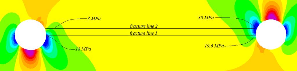
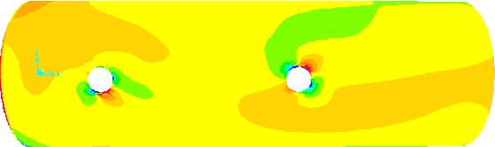
3 Thus, the elastic local displacement below the pin δ i (θ) is given by Eq. 1. δ i (θ) = R p 1 R ρ 2 R p 2 sen 2 θ + δ + i R h cosθ (1) Bamboo 4, Figure 7c has a diameter equal to d=12.7mm and mean wall thickness t = 8.2 mm. It was modeled as a thick shell and the material was considered orthotropic, with modulus of elasticity E1 = 10 GPa and E2=E3 = 1,2 GPa. Likewise the transversal modulus are G12=G13=G23= 1,2 GPa, Figure 3. The concepts of symmetry were used to decrease computing time. In this element an axial tension force equal to 20 kn is the limit to compression stress σ 11 = 80 MPa, Figure 4 a, which starts the squashing of the fibers. Two interesting results had been observed in the axial tension tests with one and two pin by ends. Independently of the occurrence of failure mode I or II, the contact compression stress stays next the limit and the possibility of the occurrence of one or another mode depends on the local thickness wall and on the moisture content of the specimen. In the case of this lot of bamboos, the shear stresses which can cause the failure of bamboo between the pins are in the order of the stresses shown in Figure 4c,d; Figures 5 and 6. Pin connections have been tested with pins of 12.7; 15.9 and 19 mm in bamboos with diameters varying from 80 to 110 mm and wall thickness from 7 to 13 mm. All presented the same mechanical performance. In the specific case of bamboo 4, Figure 7 c), the bolts were 12.7 mm and the test is considered to be the reference test. Base and Top refer to invisible and visible surface respectively. Figure 3: limit axial force F1 = - 20 kn; dp = 12,7 mm a) b) c) d) e) f) Figure 4: a)s11 BASE; b)s11 TOP; c)s13 BASE; d)s13 TOP; e)s33 BASE; f)s33 TOP


 b) c) d) Figure 7 : a), b)connection under combined")
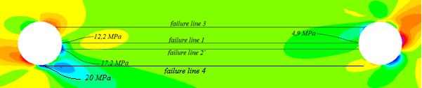
4 Figure 5: Shear S13 BASE zoom and possible shear failure line Figure 6: Shear S13 TOP zoom and possible shear failure line The forces between pins are of neglegible difference; the pin of the left carries 52 % of the applied load and equal forces can be considered to occur between pins in the structure. But when axial forces were combined with bending moments, the things changed completely. Figure 7 shows the specimen CP2, Moreira & Gaspar [2], one of the 3 different specimens tested in compression. Two bamboos are pin connected to 4 bamboos through 4 steel pins with 12,7 mm in diameter with an internal angle of a) b) c) d) Figure 7 : a), b)connection under combined actions; c)cracks over bars 3 and 4 ; d) Crack on bar 6
 shows the relation between applied moment M versus distortion γ.")
 shows the scheme of the tests; Figure 9 b) the numeration of the bars and Figure 9 c) shows the geometric relations.")

5 Loads P(N) The first cracks occur on bar 4 and bar 3, simultaneously with the load of 7 kn, Figure 8 a), before the ultimate load equal 8,8 kn. Figure 8 b) shows the relation between applied moment M versus distortion γ Vertical displacements (mm) a) b) Figure 8 : a) Load P versus vertical displacement δ; b) Moments M vs angular displacement γ Figure 9 a) shows the scheme of the tests; Figure 9 b) the numeration of the bars and Figure 9 c) shows the geometric relations. Bar 3 was thouroughly investigated beforehand because it was also under tension force. Bar 4, subjected to bigger forces than bar 3, was also investigated and is presented here in this paper. a) b) c) Figure 9: a) Test squeme; b) Numeration of bars; c) Test structural system The results of numerical modeling through FEM, Moreira e Gaspar [2 ], with the load P = 7 kn, limit of proportionality, are shown in Figure 10 a) and b). Figure 10 : a) bending moments on bars 3 and 4; b) axial forces on bars 3 and 4


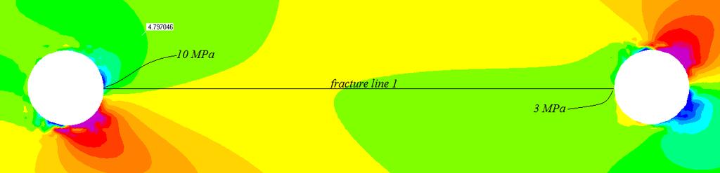
6 In this modeling, Figure 10, bamboos were considered as pipe bar elements. Then the element 4 was modeled as follows. The strings were positioned according to the resultant R of forces in the hole, as seen in Figure 11. Figure 11: Position of springs in pin- hole contact according to local forces Figure 12 shows the results for simultaneous actions of moments and compression forces. Figure 13 shows the results for the application of only moment and Figure 14 the results for tension axial force and moments simultaneously. a) b) c) d) e) f) Figure 12: a)loading; b) S11 BASE; c) S13BASE; d) S13 TOP; e) S33 BASE; f) S33 TOP Figure 13: S13 BASE ZOOM


 b) c)")


s13")
s13 TOP;")
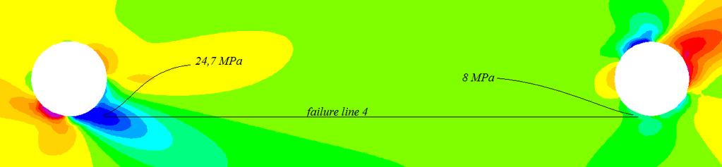
7 Figure 14: S33 BASE - ZOOM Figure 15: S13 TOP ZOOM Figure 16: S33 TOP ZOOM a) b) c) d) e) Figure 17 : a) FAILURE MOMENT b)s13 BASE; c)s13 TOP; d)s33 BASE; e)s33 TOP


8 Figure 18: S13 BASE ZOOM Figure 19: S33 BASE ZOOM Figure 20: S13 TOP ZOOM Figure 21: S33 TOP ZOOM
 e) f)")

9 a) b) c) d) e) f) Figure 22 : a)loading; b) S11 BASE; c) S13 BASE; d) S13 TOP; e) S33 BASE; f)s33 TOP Figure 23: S13 BASE ZOOM Figure 24: S33 BASE ZOOM Figure 25: S13 TOP ZOOM

10 Figure 26: S33 TOP ZOOM The heterogeneity of bamboo anatomy shows clearly that the simultaneous application of moments and axial forces give results completely different of the superposition of the isolated effects. This is because bamboo is fibre oriented and the inclination of the contact zone between pin and hole increases the local resistance when the bar is compressed and decreases it when tensioned. The curves of stress distribution along the possible failure lines is relatively easy to make but in this paper was done preference to images and color scale. The Saint Vennant Principle is visible all over pictures. The comparison of the stress fields in each case, including the analysis of the bar 3 under simultaneous actions of tension and bending moments, not presented in this paper, permits consider the Limit State Diagram Design to verify connection resistance, Figure 27. In this Figure, P1 and P2 are the solicitations of bar 4 and 3 in the instant of the appearance of first cracks on the mechanical test, under the load of 7 kn. To use the proposed diagram for different species and geometries, it is necessary to determine the new values of M and F to the selected lot of bamboos, according to Eq. 2 and Eq.3, and then to make the particular diagram to the lot. So, this diagram refers to the reference lot caracterized in our laboratories which have the mechanical properties of reference given in Table 2. Table 2 : Physical and mechanical reference properties (Phyllostachys pubescens species) Moisture content % σr (MPa) τr (MPa) Density (kn/m 3 ) 7.5± ± ±0.9 7.,7 It was used also as reference, the diameter of the pin dpr = 12,7 mm; bamboo thickness wall equal tr = 8,2 mm; moment in the connection M =Mr =0,4 knm; axial force F = Fr = 20 kn. M = M r t t r τ τ r d p d pr σ 90 σ r90 (2) F = 2 F r t t r d p d r τ τ r σ σ r (3)
, fixed by one bolt and 2 bolts at ends, is evaluated as an example.")


11 Figure 27: Limit State Design Diagram and Safety Region As can be seen in Figure 27, the safety region in green color was obtained to a safety factor equal 2 applied on M and F. This procedure was used to calculate the structure of the Figure 29, where the bar indicated in Figure 29 a), fixed by one bolt and 2 bolts at ends, is evaluated as an example. Figure 28 a) shows the axial force F = -4 kn and Figure 28 b) the bending moment M = 0,15 knm. This point is inside the safety region of the Figure 27 and show us that only one bar can absorb the solicitation if the bar is selected with thickness wall greater than dpr = 8,2 mm, although there is two parallel bars in this position due to buckling problems of the same stick. The limit normal stress perpendicular to fibers σ r90 is considered equal a quarter of the normal stress parallel to fibers σ r, or σ r90 = 0,25σ r. a) b) Figure 28: a) axial forces; b) bending moments The structure was used for a Chapel for the novel Araguaia of the Television Globo Net. Figure 29 c) shows the chapel which was designed through engineering concepts and a tower on the left which was constructed intuitively. In this second case there is a large and visible eccentricity on the connections, what is not a good solution.


12 b) a) c) Figure 29 a,b,c: Connections investigated through the LIMIT STATE DESIGN DIAGRAM Conclusions The resistance of bolt connections decreases when axial forces are superimposed to bending moments especially when combined with tension forces. In this case, the Limit State Diagram Design and Safety Region developed here is a practical way to verify connections in this common type of structures and can be improved if a major number of specimens are tested in the future. After many investigations of the stress field it was concluded that the maximum axial force can be limited by the squashing of the fibres in the contact area, or mode failure I. The occurrence of failure mode I or II depends on the local thickness wall and on the moisture content of the specimen, but in both cases the contact stress attain the squashing of the fibres. Moisture content equal 15% or more tend to failure by progressive squashing of the fibres followed by splitting mode III. Acknowledgements The authors thank to the Brazilian Council of Scientific and Technological Development - CNPq by research funding. The authors also thank Ana Paula Nardy Nascimento for executing part of the analysis developed here and to the designer Pedro Orlando Botelho by Chapel photographs presented in this paper
13 ] References [1] Moreira, L.E and Ghavami, K. Limits States Analysis for Bamboo Pin Connections. Key Engineering Materials (on line), v. 517, 2012, p [2] Moreira, L. E. and Gaspar, I. C.P. Functioning of Bolted Connections for Bamboo Structures under Bending Moments, Shear and Axial Forces. Proceedings of the Non Conventional Materials and Technologies International Congress XIV XIV NOCMAT, João Pessoa, PB, Brazil, 2013.
Name :. Roll No. :... Invigilator s Signature :.. CS/B.TECH (CE-NEW)/SEM-3/CE-301/ SOLID MECHANICS
/SEM-3/CE-301/ SOLID MECHANICS") Name :. Roll No. :..... Invigilator s Signature :.. 2011 SOLID MECHANICS Time Allotted : 3 Hours Full Marks : 70 The figures in the margin indicate full marks. Candidates are required to give their answers
Name :. Roll No. :..... Invigilator s Signature :.. 2011 SOLID MECHANICS Time Allotted : 3 Hours Full Marks : 70 The figures in the margin indicate full marks. Candidates are required to give their answers
Stress Analysis Lecture 3 ME 276 Spring Dr./ Ahmed Mohamed Nagib Elmekawy
 Stress Analysis Lecture 3 ME 276 Spring 2017-2018 Dr./ Ahmed Mohamed Nagib Elmekawy Axial Stress 2 Beam under the action of two tensile forces 3 Beam under the action of two tensile forces 4 Shear Stress
Structural Analysis I Chapter 4 - Torsion TORSION
 ORSION orsional stress results from the action of torsional or twisting moments acting about the longitudinal axis of a shaft. he effect of the application of a torsional moment, combined with appropriate
D : SOLID MECHANICS. Q. 1 Q. 9 carry one mark each. Q.1 Find the force (in kn) in the member BH of the truss shown.
 in the member BH of the truss shown.") D : SOLID MECHANICS Q. 1 Q. 9 carry one mark each. Q.1 Find the force (in kn) in the member BH of the truss shown. Q.2 Consider the forces of magnitude F acting on the sides of the regular hexagon having
D : SOLID MECHANICS Q. 1 Q. 9 carry one mark each. Q.1 Find the force (in kn) in the member BH of the truss shown. Q.2 Consider the forces of magnitude F acting on the sides of the regular hexagon having
Question 1. Ignore bottom surface. Solution: Design variables: X = (R, H) Objective function: maximize volume, πr 2 H OR Minimize, f(x) = πr 2 H
 Objective function: maximize volume, πr 2 H OR Minimize, f(x) = πr 2 H") Question 1 (Problem 2.3 of rora s Introduction to Optimum Design): Design a beer mug, shown in fig, to hold as much beer as possible. The height and radius of the mug should be not more than 20 cm. The
Question 1 (Problem 2.3 of rora s Introduction to Optimum Design): Design a beer mug, shown in fig, to hold as much beer as possible. The height and radius of the mug should be not more than 20 cm. The
Samantha Ramirez, MSE. Stress. The intensity of the internal force acting on a specific plane (area) passing through a point. F 2
 passing through a point. F 2") Samantha Ramirez, MSE Stress The intensity of the internal force acting on a specific plane (area) passing through a point. Δ ΔA Δ z Δ 1 2 ΔA Δ x Δ y ΔA is an infinitesimal size area with a uniform force
Samantha Ramirez, MSE Stress The intensity of the internal force acting on a specific plane (area) passing through a point. Δ ΔA Δ z Δ 1 2 ΔA Δ x Δ y ΔA is an infinitesimal size area with a uniform force
Mechanics of Materials MENG 270 Fall 2003 Exam 3 Time allowed: 90min. Q.1(a) Q.1 (b) Q.2 Q.3 Q.4 Total
 Q.1 (b) Q.2 Q.3 Q.4 Total") Mechanics of Materials MENG 70 Fall 00 Eam Time allowed: 90min Name. Computer No. Q.(a) Q. (b) Q. Q. Q.4 Total Problem No. (a) [5Points] An air vessel is 500 mm average diameter and 0 mm thickness, the
Mechanics of Materials MENG 70 Fall 00 Eam Time allowed: 90min Name. Computer No. Q.(a) Q. (b) Q. Q. Q.4 Total Problem No. (a) [5Points] An air vessel is 500 mm average diameter and 0 mm thickness, the
ME Final Exam. PROBLEM NO. 4 Part A (2 points max.) M (x) y. z (neutral axis) beam cross-sec+on. 20 kip ft. 0.2 ft. 10 ft. 0.1 ft.
 M (x) y. z (neutral axis) beam cross-sec+on. 20 kip ft. 0.2 ft. 10 ft. 0.1 ft.") ME 323 - Final Exam Name December 15, 2015 Instructor (circle) PROEM NO. 4 Part A (2 points max.) Krousgrill 11:30AM-12:20PM Ghosh 2:30-3:20PM Gonzalez 12:30-1:20PM Zhao 4:30-5:20PM M (x) y 20 kip ft 0.2
ME 323 - Final Exam Name December 15, 2015 Instructor (circle) PROEM NO. 4 Part A (2 points max.) Krousgrill 11:30AM-12:20PM Ghosh 2:30-3:20PM Gonzalez 12:30-1:20PM Zhao 4:30-5:20PM M (x) y 20 kip ft 0.2
[5] Stress and Strain
![[5] Stress and Strain](/thumbs/95/123344550.jpg "[5] Stress and Strain") [5] Stress and Strain Page 1 of 34 [5] Stress and Strain [5.1] Internal Stress of Solids [5.2] Design of Simple Connections (will not be covered in class) [5.3] Deformation and Strain [5.4] Hooke s Law
[5] Stress and Strain Page 1 of 34 [5] Stress and Strain [5.1] Internal Stress of Solids [5.2] Design of Simple Connections (will not be covered in class) [5.3] Deformation and Strain [5.4] Hooke s Law
N = Shear stress / Shear strain
 UNIT - I 1. What is meant by factor of safety? [A/M-15] It is the ratio between ultimate stress to the working stress. Factor of safety = Ultimate stress Permissible stress 2. Define Resilience. [A/M-15]
STRESS, STRAIN AND DEFORMATION OF SOLIDS
 VELAMMAL COLLEGE OF ENGINEERING AND TECHNOLOGY, MADURAI 625009 DEPARTMENT OF CIVIL ENGINEERING CE8301 STRENGTH OF MATERIALS I -------------------------------------------------------------------------------------------------------------------------------
QUESTION BANK SEMESTER: III SUBJECT NAME: MECHANICS OF SOLIDS
 QUESTION BANK SEMESTER: III SUBJECT NAME: MECHANICS OF SOLIDS UNIT 1- STRESS AND STRAIN PART A (2 Marks) 1. Define longitudinal strain and lateral strain. 2. State Hooke s law. 3. Define modular ratio,
Strength of Material. Shear Strain. Dr. Attaullah Shah
 Strength of Material Shear Strain Dr. Attaullah Shah Shear Strain TRIAXIAL DEFORMATION Poisson's Ratio Relationship Between E, G, and ν BIAXIAL DEFORMATION Bulk Modulus of Elasticity or Modulus of Volume
The University of Melbourne Engineering Mechanics
 The University of Melbourne 436-291 Engineering Mechanics Tutorial Four Poisson s Ratio and Axial Loading Part A (Introductory) 1. (Problem 9-22 from Hibbeler - Statics and Mechanics of Materials) A short
NORMAL STRESS. The simplest form of stress is normal stress/direct stress, which is the stress perpendicular to the surface on which it acts.
 NORMAL STRESS The simplest form of stress is normal stress/direct stress, which is the stress perpendicular to the surface on which it acts. σ = force/area = P/A where σ = the normal stress P = the centric
CHAPTER 3 THE EFFECTS OF FORCES ON MATERIALS
 CHAPTER THE EFFECTS OF FORCES ON MATERIALS EXERCISE 1, Page 50 1. A rectangular bar having a cross-sectional area of 80 mm has a tensile force of 0 kn applied to it. Determine the stress in the bar. Stress
COLUMNS: BUCKLING (DIFFERENT ENDS)
") COLUMNS: BUCKLING (DIFFERENT ENDS) Buckling of Long Straight Columns Example 4 Slide No. 1 A simple pin-connected truss is loaded and supported as shown in Fig. 1. All members of the truss are WT10 43
COLUMNS: BUCKLING (DIFFERENT ENDS) Buckling of Long Straight Columns Example 4 Slide No. 1 A simple pin-connected truss is loaded and supported as shown in Fig. 1. All members of the truss are WT10 43
QUESTION BANK DEPARTMENT: CIVIL SEMESTER: III SUBJECT CODE: CE2201 SUBJECT NAME: MECHANICS OF SOLIDS UNIT 1- STRESS AND STRAIN PART A
 DEPARTMENT: CIVIL SUBJECT CODE: CE2201 QUESTION BANK SEMESTER: III SUBJECT NAME: MECHANICS OF SOLIDS UNIT 1- STRESS AND STRAIN PART A (2 Marks) 1. Define longitudinal strain and lateral strain. 2. State
IDE 110 Mechanics of Materials Spring 2006 Final Examination FOR GRADING ONLY
 Spring 2006 Final Examination STUDENT S NAME (please print) STUDENT S SIGNATURE STUDENT NUMBER IDE 110 CLASS SECTION INSTRUCTOR S NAME Do not turn this page until instructed to start. Write your name on
Downloaded from Downloaded from / 1
 PURWANCHAL UNIVERSITY III SEMESTER FINAL EXAMINATION-2002 LEVEL : B. E. (Civil) SUBJECT: BEG256CI, Strength of Material Full Marks: 80 TIME: 03:00 hrs Pass marks: 32 Candidates are required to give their
Mechanics of Materials II. Chapter III. A review of the fundamental formulation of stress, strain, and deflection
 Mechanics of Materials II Chapter III A review of the fundamental formulation of stress, strain, and deflection Outline Introduction Assumtions and limitations Axial loading Torsion of circular shafts
KINGS COLLEGE OF ENGINEERING DEPARTMENT OF MECHANICAL ENGINEERING QUESTION BANK. Subject code/name: ME2254/STRENGTH OF MATERIALS Year/Sem:II / IV
 KINGS COLLEGE OF ENGINEERING DEPARTMENT OF MECHANICAL ENGINEERING QUESTION BANK Subject code/name: ME2254/STRENGTH OF MATERIALS Year/Sem:II / IV UNIT I STRESS, STRAIN DEFORMATION OF SOLIDS PART A (2 MARKS)
Entrance exam Master Course
 - 1 - Guidelines for completion of test: On each page, fill in your name and your application code Each question has four answers while only one answer is correct. o Marked correct answer means 4 points
PERIYAR CENTENARY POLYTECHNIC COLLEGE PERIYAR NAGAR - VALLAM THANJAVUR. DEPARTMENT OF MECHANICAL ENGINEERING QUESTION BANK
 PERIYAR CENTENARY POLYTECHNIC COLLEGE PERIYAR NAGAR - VALLAM - 613 403 - THANJAVUR. DEPARTMENT OF MECHANICAL ENGINEERING QUESTION BANK Sub : Strength of Materials Year / Sem: II / III Sub Code : MEB 310
UNIT 1 STRESS STRAIN AND DEFORMATION OF SOLIDS, STATES OF STRESS 1. Define stress. When an external force acts on a body, it undergoes deformation.
 UNIT 1 STRESS STRAIN AND DEFORMATION OF SOLIDS, STATES OF STRESS 1. Define stress. When an external force acts on a body, it undergoes deformation. At the same time the body resists deformation. The magnitude
2012 MECHANICS OF SOLIDS
 R10 SET - 1 II B.Tech II Semester, Regular Examinations, April 2012 MECHANICS OF SOLIDS (Com. to ME, AME, MM) Time: 3 hours Max. Marks: 75 Answer any FIVE Questions All Questions carry Equal Marks ~~~~~~~~~~~~~~~~~~~~~~
and F NAME: ME rd Sample Final Exam PROBLEM 1 (25 points) Prob. 1 questions are all or nothing. PROBLEM 1A. (5 points)
 Prob. 1 questions are all or nothing. PROBLEM 1A. (5 points)") ME 270 3 rd Sample inal Exam PROBLEM 1 (25 points) Prob. 1 questions are all or nothing. PROBLEM 1A. (5 points) IND: In your own words, please state Newton s Laws: 1 st Law = 2 nd Law = 3 rd Law = PROBLEM
ME 270 3 rd Sample inal Exam PROBLEM 1 (25 points) Prob. 1 questions are all or nothing. PROBLEM 1A. (5 points) IND: In your own words, please state Newton s Laws: 1 st Law = 2 nd Law = 3 rd Law = PROBLEM
Mechanics of Materials CIVL 3322 / MECH 3322
 Mechanics of Materials CIVL 3322 / MECH 3322 2 3 4 5 6 7 8 9 10 A Quiz 11 A Quiz 12 A Quiz 13 A Quiz 14 A Quiz 15 A Quiz 16 In Statics, we spent most of our time looking at reactions at supports Two variations
Analysis of asymmetric radial deformation in pipe with local wall thinning under internal pressure using strain energy method
 Analysis of asymmetric radial deformation in pipe with local wall thinning under internal pressure using strain energy method V.M.F. Nascimento Departameto de ngenharia Mecânica TM, UFF, Rio de Janeiro
D : SOLID MECHANICS. Q. 1 Q. 9 carry one mark each.
 GTE 2016 Q. 1 Q. 9 carry one mark each. D : SOLID MECHNICS Q.1 single degree of freedom vibrating system has mass of 5 kg, stiffness of 500 N/m and damping coefficient of 100 N-s/m. To make the system
Stress Analysis Lecture 4 ME 276 Spring Dr./ Ahmed Mohamed Nagib Elmekawy
 Stress Analysis Lecture 4 ME 76 Spring 017-018 Dr./ Ahmed Mohamed Nagib Elmekawy Shear and Moment Diagrams Beam Sign Convention The positive directions are as follows: The internal shear force causes a
A FINITE ELEMENT MODEL FOR SIZE EFFECT AND HETEROGENEITY IN CONCRETE STRUCTURES
 A FINITE ELEMENT MODEL FOR SIZE EFFECT AND HETEROGENEITY IN CONCRETE STRUCTURES Roque Luiz Pitangueira 1 and Raul Rosas e Silva 2 1 Department of Structural Engineering -Federal University of Minas Gerais
Only for Reference Page 1 of 18
 Only for Reference www.civilpddc2013.weebly.com Page 1 of 18 Seat No.: Enrolment No. GUJARAT TECHNOLOGICAL UNIVERSITY PDDC - SEMESTER II EXAMINATION WINTER 2013 Subject Code: X20603 Date: 26-12-2013 Subject
Advanced Structural Analysis EGF Section Properties and Bending
 Advanced Structural Analysis EGF316 3. Section Properties and Bending 3.1 Loads in beams When we analyse beams, we need to consider various types of loads acting on them, for example, axial forces, shear
SRI CHANDRASEKHARENDRA SARASWATHI VISWA MAHAVIDHYALAYA
 SRI CHANDRASEKHARENDRA SARASWATHI VISWA MAHAVIDHYALAYA (Declared as Deemed-to-be University under Section 3 of the UGC Act, 1956, Vide notification No.F.9.9/92-U-3 dated 26 th May 1993 of the Govt. of
Civil Engineering Design (1) Design of Reinforced Concrete Columns 2006/7
 Design of Reinforced Concrete Columns 2006/7") Civil Engineering Design (1) Design of Reinforced Concrete Columns 2006/7 Dr. Colin Caprani, Chartered Engineer 1 Contents 1. Introduction... 3 1.1 Background... 3 1.2 Failure Modes... 5 1.3 Design Aspects...
Civil Engineering Design (1) Design of Reinforced Concrete Columns 2006/7 Dr. Colin Caprani, Chartered Engineer 1 Contents 1. Introduction... 3 1.1 Background... 3 1.2 Failure Modes... 5 1.3 Design Aspects...
Critical Load columns buckling critical load
 Buckling of Columns Buckling of Columns Critical Load Some member may be subjected to compressive loadings, and if these members are long enough to cause the member to deflect laterally or sideway. To
CIV 207 Winter For practice
 CIV 07 Winter 009 Assignment #10 Friday, March 0 th Complete the first three questions. Submit your work to Box #5 on the th floor of the MacDonald building by 1 noon on Tuesday March 31 st. No late submissions
CHAPTER 4: BENDING OF BEAMS
 (74) CHAPTER 4: BENDING OF BEAMS This chapter will be devoted to the analysis of prismatic members subjected to equal and opposite couples M and M' acting in the same longitudinal plane. Such members are
Final Analysis Report MIE 313 Design of Mechanical Components
 Final Analysis Report MIE 313 Design of Mechanical Components Juliana Amado Charlene Nestor Peter Walsh Table of Contents Abstract:...iii Introduction:... 4 Procedure:... 5 Results:... 6 Reliability:...
Determine the resultant internal loadings acting on the cross section at C of the beam shown in Fig. 1 4a.
 E X M P L E 1.1 Determine the resultant internal loadings acting on the cross section at of the beam shown in Fig. 1 a. 70 N/m m 6 m Fig. 1 Support Reactions. This problem can be solved in the most direct
Question 1. Ignore bottom surface. Problem formulation: Design variables: X = (R, H)
") Question 1 (Problem 2.3 of Arora s Introduction to Optimum Design): Design a beer mug, shown in fig, to hold as much beer as possible. The height and radius of the mug should be not more than 20 cm. The
Question 1 (Problem 2.3 of Arora s Introduction to Optimum Design): Design a beer mug, shown in fig, to hold as much beer as possible. The height and radius of the mug should be not more than 20 cm. The
MECHANICS OF MATERIALS. Prepared by Engr. John Paul Timola
 MECHANICS OF MATERIALS Prepared by Engr. John Paul Timola Mechanics of materials branch of mechanics that studies the internal effects of stress and strain in a solid body. stress is associated with the
FLEXIBILITY METHOD FOR INDETERMINATE FRAMES
 UNIT - I FLEXIBILITY METHOD FOR INDETERMINATE FRAMES 1. What is meant by indeterminate structures? Structures that do not satisfy the conditions of equilibrium are called indeterminate structure. These
DEPARTMENT OF CIVIL ENGINEERING
 KINGS COLLEGE OF ENGINEERING DEPARTMENT OF CIVIL ENGINEERING SUBJECT: CE 2252 STRENGTH OF MATERIALS UNIT: I ENERGY METHODS 1. Define: Strain Energy When an elastic body is under the action of external
2. Rigid bar ABC supports a weight of W = 50 kn. Bar ABC is pinned at A and supported at B by rod (1). What is the axial force in rod (1)?
. What is the axial force in rod (1)?") IDE 110 S08 Test 1 Name: 1. Determine the internal axial forces in segments (1), (2) and (3). (a) N 1 = kn (b) N 2 = kn (c) N 3 = kn 2. Rigid bar ABC supports a weight of W = 50 kn. Bar ABC is pinned at
IDE 110 S08 Test 1 Name: 1. Determine the internal axial forces in segments (1), (2) and (3). (a) N 1 = kn (b) N 2 = kn (c) N 3 = kn 2. Rigid bar ABC supports a weight of W = 50 kn. Bar ABC is pinned at
PES Institute of Technology
 PES Institute of Technology Bangalore south campus, Bangalore-5460100 Department of Mechanical Engineering Faculty name : Madhu M Date: 29/06/2012 SEM : 3 rd A SEC Subject : MECHANICS OF MATERIALS Subject
STRUCTURAL RESPONSE OF K AND T TUBULAR JOINTS UNDER STATIC LOADING
 STRUCTURAL RESPONSE OF K AND T TUBULAR JOINTS UNDER STATIC LOADING Luciano R. O. de Lima, Pedro C. G. da S. Vellasco, Sebastião A. L. de Andrade Structural Engineering Department, UERJ, Rio de Janeiro,
ENG1001 Engineering Design 1
 ENG1001 Engineering Design 1 Structure & Loads Determine forces that act on structures causing it to deform, bend, and stretch Forces push/pull on objects Structures are loaded by: > Dead loads permanent
five Mechanics of Materials 1 ARCHITECTURAL STRUCTURES: FORM, BEHAVIOR, AND DESIGN DR. ANNE NICHOLS SUMMER 2017 lecture
 ARCHITECTURAL STRUCTURES: FORM, BEHAVIOR, AND DESIGN DR. ANNE NICHOLS SUMMER 2017 lecture five mechanics www.carttalk.com of materials Mechanics of Materials 1 Mechanics of Materials MECHANICS MATERIALS
March 24, Chapter 4. Deflection and Stiffness. Dr. Mohammad Suliman Abuhaiba, PE
 Chapter 4 Deflection and Stiffness 1 2 Chapter Outline Spring Rates Tension, Compression, and Torsion Deflection Due to Bending Beam Deflection Methods Beam Deflections by Superposition Strain Energy Castigliano
Lecture 4 Honeycombs Notes, 3.054
 Honeycombs-In-plane behavior Lecture 4 Honeycombs Notes, 3.054 Prismatic cells Polymer, metal, ceramic honeycombs widely available Used for sandwich structure cores, energy absorption, carriers for catalysts
INTRODUCTION TO STRAIN
 SIMPLE STRAIN INTRODUCTION TO STRAIN In general terms, Strain is a geometric quantity that measures the deformation of a body. There are two types of strain: normal strain: characterizes dimensional changes,
R13. II B. Tech I Semester Regular Examinations, Jan MECHANICS OF SOLIDS (Com. to ME, AME, AE, MTE) PART-A
 PART-A") SET - 1 II B. Tech I Semester Regular Examinations, Jan - 2015 MECHANICS OF SOLIDS (Com. to ME, AME, AE, MTE) Time: 3 hours Max. Marks: 70 Note: 1. Question Paper consists of two parts (Part-A and Part-B)
SET - 1 II B. Tech I Semester Regular Examinations, Jan - 2015 MECHANICS OF SOLIDS (Com. to ME, AME, AE, MTE) Time: 3 hours Max. Marks: 70 Note: 1. Question Paper consists of two parts (Part-A and Part-B)
Unit III Theory of columns. Dr.P.Venkateswara Rao, Associate Professor, Dept. of Civil Engg., SVCE, Sriperumbudir
 Unit III Theory of columns 1 Unit III Theory of Columns References: Punmia B.C.,"Theory of Structures" (SMTS) Vol II, Laxmi Publishing Pvt Ltd, New Delhi 2004. Rattan.S.S., "Strength of Materials", Tata
CHAPTER 2 Failure/Fracture Criterion
 (11) CHAPTER 2 Failure/Fracture Criterion (12) Failure (Yield) Criteria for Ductile Materials under Plane Stress Designer engineer: 1- Analysis of loading (for simple geometry using what you learn here
Russell C. Hibbeler. Chapter 1: Stress
 Russell C. Hibbeler Chapter 1: Stress Introduction Mechanics of materials is a study of the relationship between the external loads on a body and the intensity of the internal loads within the body. This
Tuesday, February 11, Chapter 3. Load and Stress Analysis. Dr. Mohammad Suliman Abuhaiba, PE
 1 Chapter 3 Load and Stress Analysis 2 Chapter Outline Equilibrium & Free-Body Diagrams Shear Force and Bending Moments in Beams Singularity Functions Stress Cartesian Stress Components Mohr s Circle for
CIVIL DEPARTMENT MECHANICS OF STRUCTURES- ASSIGNMENT NO 1. Brach: CE YEAR:
 MECHANICS OF STRUCTURES- ASSIGNMENT NO 1 SEMESTER: V 1) Find the least moment of Inertia about the centroidal axes X-X and Y-Y of an unequal angle section 125 mm 75 mm 10 mm as shown in figure 2) Determine
Chapter 8 Structural Design and Analysis. Strength and stiffness 5 types of load: Tension Compression Shear Bending Torsion
 Chapter 8 Structural Design and Analysis 1 Strength and stiffness 5 types of load: Tension Compression Shear Bending Torsion Normal Stress Stress is a state when a material is loaded. For normal forces
EDEXCEL NATIONAL CERTIFICATE/DIPLOMA MECHANICAL PRINCIPLES AND APPLICATIONS NQF LEVEL 3 OUTCOME 1 - LOADING SYSTEMS TUTORIAL 3 LOADED COMPONENTS
 EDEXCEL NATIONAL CERTIICATE/DIPLOMA MECHANICAL PRINCIPLES AND APPLICATIONS NQ LEVEL 3 OUTCOME 1 - LOADING SYSTEMS TUTORIAL 3 LOADED COMPONENTS 1. Be able to determine the effects of loading in static engineering
PDDC 1 st Semester Civil Engineering Department Assignments of Mechanics of Solids [ ] Introduction, Fundamentals of Statics
![PDDC 1 st Semester Civil Engineering Department Assignments of Mechanics of Solids [ ] Introduction, Fundamentals of Statics](/thumbs/92/109382806.jpg "PDDC 1 st Semester Civil Engineering Department Assignments of Mechanics of Solids [ ] Introduction, Fundamentals of Statics") Page1 PDDC 1 st Semester Civil Engineering Department Assignments of Mechanics of Solids [2910601] Introduction, Fundamentals of Statics 1. Differentiate between Scalar and Vector quantity. Write S.I.
Page1 PDDC 1 st Semester Civil Engineering Department Assignments of Mechanics of Solids [2910601] Introduction, Fundamentals of Statics 1. Differentiate between Scalar and Vector quantity. Write S.I.
BME 207 Introduction to Biomechanics Spring 2017
 April 7, 2017 UNIVERSITY OF RHODE ISAND Department of Electrical, Computer and Biomedical Engineering BE 207 Introduction to Biomechanics Spring 2017 Homework 7 Problem 14.3 in the textbook. In addition
INSTITUTE OF AERONAUTICAL ENGINEERING (Autonomous) Dundigal, Hyderabad
 Dundigal, Hyderabad") INSTITUTE OF AERONAUTICAL ENGINEERING (Autonomous) Dundigal, Hyderabad -00 04 CIVIL ENGINEERING QUESTION BANK Course Name : STRENGTH OF MATERIALS II Course Code : A404 Class : II B. Tech II Semester Section
INSTITUTE OF AERONAUTICAL ENGINEERING (Autonomous) Dundigal, Hyderabad -00 04 CIVIL ENGINEERING QUESTION BANK Course Name : STRENGTH OF MATERIALS II Course Code : A404 Class : II B. Tech II Semester Section
9.5 Compression Members
 9.5 Compression Members This section covers the following topics. Introduction Analysis Development of Interaction Diagram Effect of Prestressing Force 9.5.1 Introduction Prestressing is meaningful when
BEAMS AND PLATES ANALYSIS
 BEAMS AND PLATES ANALYSIS Automotive body structure can be divided into two types: i. Frameworks constructed of beams ii. Panels Classical beam versus typical modern vehicle beam sections Assumptions:
Failure analysis of serial pinned joints in composite materials
 Indian Journal of Engineering & Materials Sciences Vol. 18, April 2011, pp. 102-110 Failure analysis of serial pinned joints in composite materials Alaattin Aktaş* Department of Mechanical Engineering,
Chapter 5 CENTRIC TENSION OR COMPRESSION ( AXIAL LOADING )
") Chapter 5 CENTRIC TENSION OR COMPRESSION ( AXIAL LOADING ) 5.1 DEFINITION A construction member is subjected to centric (axial) tension or compression if in any cross section the single distinct stress
Chapter 5 CENTRIC TENSION OR COMPRESSION ( AXIAL LOADING ) 5.1 DEFINITION A construction member is subjected to centric (axial) tension or compression if in any cross section the single distinct stress
UNIT-I STRESS, STRAIN. 1. A Member A B C D is subjected to loading as shown in fig determine the total elongation. Take E= 2 x10 5 N/mm 2
 UNIT-I STRESS, STRAIN 1. A Member A B C D is subjected to loading as shown in fig determine the total elongation. Take E= 2 x10 5 N/mm 2 Young s modulus E= 2 x10 5 N/mm 2 Area1=900mm 2 Area2=400mm 2 Area3=625mm
CIVL222 STRENGTH OF MATERIALS. Chapter 6. Torsion
 CIVL222 STRENGTH OF MATERIALS Chapter 6 Torsion Definition Torque is a moment that tends to twist a member about its longitudinal axis. Slender members subjected to a twisting load are said to be in torsion.
STRENGTH OF MATERIALS-I. Unit-1. Simple stresses and strains
 STRENGTH OF MATERIALS-I Unit-1 Simple stresses and strains 1. What is the Principle of surveying 2. Define Magnetic, True & Arbitrary Meridians. 3. Mention different types of chains 4. Differentiate between
Numerical Characterization of Concrete Heterogeneity
 Vol. Materials 5, No. Research, 3, 2002Vol. 5, No. 3, Statistical 309-314, 2002. Characterization of the Concrete Numerical Modeling of Size Effect In Heterogeneity 2002 309 Numerical Characterization
2. Polar moment of inertia As stated above, the polar second moment of area, J is defined as. Sample copy
 GATE PATHSHALA - 91. Polar moment of inertia As stated above, the polar second moment of area, is defined as z π r dr 0 R r π R π D For a solid shaft π (6) QP 0 π d Solid shaft π d Hollow shaft, " ( do
Mechanics of Solids. Mechanics Of Solids. Suraj kr. Ray Department of Civil Engineering
 Mechanics Of Solids Suraj kr. Ray (surajjj2445@gmail.com) Department of Civil Engineering 1 Mechanics of Solids is a branch of applied mechanics that deals with the behaviour of solid bodies subjected
18.Define the term modulus of resilience. May/June Define Principal Stress. 20. Define Hydrostatic Pressure.
 CE6306 STREGNTH OF MATERIALS Question Bank Unit-I STRESS, STRAIN, DEFORMATION OF SOLIDS PART-A 1. Define Poison s Ratio May/June 2009 2. What is thermal stress? May/June 2009 3. Estimate the load carried
Design of Beams (Unit - 8)
") Design of Beams (Unit - 8) Contents Introduction Beam types Lateral stability of beams Factors affecting lateral stability Behaviour of simple and built - up beams in bending (Without vertical stiffeners)
Design of Beams (Unit - 8) Contents Introduction Beam types Lateral stability of beams Factors affecting lateral stability Behaviour of simple and built - up beams in bending (Without vertical stiffeners)
PURE BENDING. If a simply supported beam carries two point loads of 10 kn as shown in the following figure, pure bending occurs at segment BC.
 BENDING STRESS The effect of a bending moment applied to a cross-section of a beam is to induce a state of stress across that section. These stresses are known as bending stresses and they act normally
PROBLEM #1.1 (4 + 4 points, no partial credit)
") PROBLEM #1.1 ( + points, no partial credit A thermal switch consists of a copper bar which under elevation of temperature closes a gap and closes an electrical circuit. The copper bar possesses a length
PROBLEM #1.1 ( + points, no partial credit A thermal switch consists of a copper bar which under elevation of temperature closes a gap and closes an electrical circuit. The copper bar possesses a length
MECHANICS OF MATERIALS
 Third E CHAPTER 1 Introduction MECHANICS OF MATERIALS Ferdinand P. Beer E. Russell Johnston, Jr. John T. DeWolf Lecture Notes: J. Walt Oler Texas Tech University Concept of Stress Contents Concept of Stress
Module 11 Design of Joints for Special Loading. Version 2 ME, IIT Kharagpur
 Module 11 Design of Joints for Special Loading Version ME, IIT Kharagpur Lesson Design of Eccentrically Loaded Welded Joints Version ME, IIT Kharagpur Instructional Objectives: At the end of this lesson,
Strength of Materials Prof S. K. Bhattacharya Department of Civil Engineering Indian Institute of Technology, Kharagpur Lecture - 18 Torsion - I
 Strength of Materials Prof S. K. Bhattacharya Department of Civil Engineering Indian Institute of Technology, Kharagpur Lecture - 18 Torsion - I Welcome to the first lesson of Module 4 which is on Torsion
APPENDIX 1 MODEL CALCULATION OF VARIOUS CODES
 163 APPENDIX 1 MODEL CALCULATION OF VARIOUS CODES A1.1 DESIGN AS PER NORTH AMERICAN SPECIFICATION OF COLD FORMED STEEL (AISI S100: 2007) 1. Based on Initiation of Yielding: Effective yield moment, M n
Theory at a Glance (for IES, GATE, PSU)
") 1. Stress and Strain Theory at a Glance (for IES, GATE, PSU) 1.1 Stress () When a material is subjected to an external force, a resisting force is set up within the component. The internal resistance force
1. Stress and Strain Theory at a Glance (for IES, GATE, PSU) 1.1 Stress () When a material is subjected to an external force, a resisting force is set up within the component. The internal resistance force
Influence of residual stresses in the structural behavior of. tubular columns and arches. Nuno Rocha Cima Gomes
 October 2014 Influence of residual stresses in the structural behavior of Abstract tubular columns and arches Nuno Rocha Cima Gomes Instituto Superior Técnico, Universidade de Lisboa, Portugal Contact:
STRESS STRAIN AND DEFORMATION OF SOLIDS, STATES OF STRESS
 1 UNIT I STRESS STRAIN AND DEFORMATION OF SOLIDS, STATES OF STRESS 1. Define: Stress When an external force acts on a body, it undergoes deformation. At the same time the body resists deformation. The
DEFORMATION CAPACITY OF OLDER RC SHEAR WALLS: EXPERIMENTAL ASSESSMENT AND COMPARISON WITH EUROCODE 8 - PART 3 PROVISIONS
 DEFORMATION CAPACITY OF OLDER RC SHEAR WALLS: EXPERIMENTAL ASSESSMENT AND COMPARISON WITH EUROCODE 8 - PART 3 PROVISIONS Konstantinos CHRISTIDIS 1, Emmanouil VOUGIOUKAS 2 and Konstantinos TREZOS 3 ABSTRACT
needed to buckle an ideal column. Analyze the buckling with bending of a column. Discuss methods used to design concentric and eccentric columns.
 CHAPTER OBJECTIVES Discuss the behavior of columns. Discuss the buckling of columns. Determine the axial load needed to buckle an ideal column. Analyze the buckling with bending of a column. Discuss methods
ROTATING RING. Volume of small element = Rdθbt if weight density of ring = ρ weight of small element = ρrbtdθ. Figure 1 Rotating ring
 ROTATIONAL STRESSES INTRODUCTION High centrifugal forces are developed in machine components rotating at a high angular speed of the order of 100 to 500 revolutions per second (rps). High centrifugal force
GATE SOLUTIONS E N G I N E E R I N G
 GATE SOLUTIONS C I V I L E N G I N E E R I N G From (1987-018) Office : F-16, (Lower Basement), Katwaria Sarai, New Delhi-110016 Phone : 011-65064 Mobile : 81309090, 9711853908 E-mail: info@iesmasterpublications.com,
D e s i g n o f R i v e t e d J o i n t s, C o t t e r & K n u c k l e J o i n t s
 D e s i g n o f R i v e t e d J o i n t s, C o t t e r & K n u c k l e J o i n t s 1. Design of various types of riveted joints under different static loading conditions, eccentrically loaded riveted joints.
EARTHQUAKE SIMULATION TESTS OF BRIDGE COLUMN MODELS DAMAGED DURING 1995 KOBE EARTHQUAKE
 EARTHQUAKE SIMULATION TESTS OF BRIDGE COLUMN MODELS DAMAGED DURING 1995 KOBE EARTHQUAKE J. Sakai 1, S. Unjoh 2 and H. Ukon 3 1 Senior Researcher, Center for Advanced Engineering Structural Assessment and
MAHALAKSHMI ENGINEERING COLLEGE
 MAHALAKSHMI ENGINEERING COLLEGE TIRUCHIRAALLI - 6113. QUESTION WITH ANSWERS DEARTMENT : CIVIL SEMESTER: V SUB.CODE/ NAME: CE 5 / Strength of Materials UNIT 3 COULMNS ART - A ( marks) 1. Define columns
Module 5: Theories of Failure
 Module 5: Theories of Failure Objectives: The objectives/outcomes of this lecture on Theories of Failure is to enable students for 1. Recognize loading on Structural Members/Machine elements and allowable
 mportant nstructions to examiners: ) The answers should be examined by key words and not as word-to-word as given in the model answer scheme. ) The model answer and the answer written by candidate may
Unit I Stress and Strain
 Unit I Stress and Strain Stress and strain at a point Tension, Compression, Shear Stress Hooke s Law Relationship among elastic constants Stress Strain Diagram for Mild Steel, TOR steel, Concrete Ultimate
7.3 Design of members subjected to combined forces
 7.3 Design of members subjected to combined forces 7.3.1 General In the previous chapters of Draft IS: 800 LSM version, we have stipulated the codal provisions for determining the stress distribution in
ME 354, MECHANICS OF MATERIALS LABORATORY COMPRESSION AND BUCKLING
 ME 354, MECHANICS OF MATERIALS LABATY COMPRESSION AND BUCKLING PURPOSE 01 January 2000 / mgj The purpose of this exercise is to study the effects of end conditions, column length, and material properties
Unit 18 Other Issues In Buckling/Structural Instability
 Unit 18 Other Issues In Buckling/Structural Instability Readings: Rivello Timoshenko Jones 14.3, 14.5, 14.6, 14.7 (read these at least, others at your leisure ) Ch. 15, Ch. 16 Theory of Elastic Stability
SECTION A. 8 kn/m. C 3 m 3m
 SECTION Question 1 150 m 40 kn 5 kn 8 kn/m C 3 m 3m D 50 ll dimensions in mm 15 15 Figure Q1(a) Figure Q1(b) The horizontal beam CD shown in Figure Q1(a) has a uniform cross-section as shown in Figure
Chapter 3. Inertia. Force. Free Body Diagram. Net Force. Mass. quantity of matter composing a body represented by m. units are kg
 Chapter 3 Mass quantity of matter composing a body represented by m Kinetic Concepts for Analyzing Human Motion units are kg Inertia tendency to resist change in state of motion proportional to mass has