Verification Examples
|
|
|
- Magdalene Sharp
- 5 years ago
- Views:
Transcription
1 Verification Examples 2008
2 AxisVM 9 Verification Examples 2 Linear static...3 Supported bar with concentrated loads....4 Thermally loaded bar structure...5 Continously supported beam with constant distributed load...6 External prestessed beam...9 Periodically supported infinite membrane wall with constant distributed load Clamped beam examination with plane stress elements...13 Clamped thin square plate...16 Plate with fixed support and constant distributed load...18 Annular plate All edges simply supported plate with partial distributed load Clamped plate with linear distributed load...23 Hemisphere displacement...25 Nonlinear static D beam structure...28 Plate with fixed end and bending moment...30 Dynamic...33 Deep simply supported beam...34 Clamped thin rhombic plate...37 Cantilevered thin square plate...39 Cantilevered tapered membrane Flat grillages Stability...49 Simply supported beam...50 Simply supported beam...52 Design...53 N-M interaction curve of cross-section (EN :2004)...54 RC beam deflection according to EC2, EN : Required steel reinforcement of RC plate according to EC2, EN : Earth-quake design using response-spectrum method....59
3 AxisVM 9 Verification Examples 3 Linear static
4 AxisVM 9 Verification Examples 4 Software Release Number: R2 Date: Tested by: InterCAD Page number: File name: beam1.axs Thema Analysis Type Geometry Supported bar with concentrated loads. Linear analysis. Side view Section Area = 1,0 m 2 Loads Boundary Conditions Material Properties Element types Mesh Axial direction forces P 1 = -200 N, P 2 = 100 N, P 3 = -40 N Fix ends, at R 1 and R 5. E = kn / cm 2 ν = 0,3 Beam element Target Results R 1, R 5 support forces Theory AxisVM % R 1 [N] 118,00 118,00 0,00 R 5 [N] 22,00 22,00 0,00
5 AxisVM 9 Verification Examples 5 Software Release Number: R2 Date: Tested by: InterCAD Page number: File name: beam2.axs Thema Analysis Type Geometry Thermally loaded bar structure. Linear analysis. Sections: Steel: A S = π x 10-4 m 2 Copper: A C = π x 10-4 m 2 Side view Loads Boundary Conditions Material Properties Element types Target Results P = -12 kn (Point load) Temperature rise of 10 C in the structure after assembly. The upper end of bars are fixed. Steel: E S = kn / cm 2, ν = 0,3, α S = 1,2 x 10⁻⁵ C -1 Copper: E C = kn / cm 2, ν = 0,3, α C = 1,7 x 10⁻⁵ C -1 Beam element S max in the three bars. Theory AxisVM % Steel S max [MPa] ,10 Cooper S max [MPa] ,19

6 AxisVM 9 Verification Examples 6 Software Release Number: R2 Date: Tested by: InterCAD Page number: File name: beam3.axs Thema Analysis Type Geometry Continously supported beam with point loads. Linear analysis. Side view (Section width = 1,00 m, height 1 = 0,30 m, height 2 = 0,60 m) Loads Boundary Conditions Material Properties Element types Target Results P 1 = -300 kn, P 2 = kn, P 3 = -800 kn, P 4 = -450 kn Elastic supported. From A to D is K z = kn/m/m. From D to F is K z = kn/m/m. E = 3000 kn/cm 2 ν = 0,3 Three node beam element. Shear deformation is taken into account. e z, M y, V z, R z Diagram e z Diagram M y Results
7 AxisVM 9 Verification Examples 7 Diagram V z Diagram R Reference AxisVM e [%] e A [m] 0,006 0,006 0,00 e B [m] 0,009 0,009 0,00 e C [m] 0,014 0,014 0,00 e D [m] 0,015 0,015 0,00 e E [m] 0,015 0,015 0,00 e F [m] 0,013 0,013 0,00 Reference AxisVM e [%] M A [KNm] 0,0 0,0 0,00 M B [KNm] 88,5 87,5-1,13 M C [KNm] 636,2 632,8-0,53 M D [KNm] 332,8 329,7-0,93 M E [KNm] 164,2 163,3-0,55 M F [KNm] 0,0 0,0 0,00
8 AxisVM 9 Verification Examples 8 Results Reference AxisVM e [%] V A [KN] 0,0 0,0 0,00 V B [KN] 112,1 113,1 0,89 V C [KN] 646,8 647,2 0,06 V D [KN] 335,0 334,9-0,03 V E [KN] 267,8 267,5-0,11 V F [KN] 0,0 0,0 0,00 Reference AxisVM e [%] R A [KN/m 2 ] 145,7 154,0 5,70 R B [KN/m 2 ] 219,5 219,4-0,05 R C [KN/m 2 ] 343,8 346,0 0,64 R D [KN/m 2 ] 386,9 386,4-0,13 R E [KN/m 2 ] 224,5 224,7 0,09 R F [KN/m 2 ] 201,2 200,8-0,20
9 AxisVM 9 Verification Examples 9 Software Release Number: R2 Date: Tested by: InterCAD Page number: File name: beam4.axs Thema Analysis Type Geometry External prestessed beam. Linear analysis. Side view Loads Boundary Conditions Material Properties p = -50 kn /m distributed load Length change = -6,52E-3 at beam 5-6 ey = ez = = 0 at node 1 ex = ey = ez = 0 at node 4 E = 2,1E11 N / m 2 Beam 1-5, 5-6, 6-4 A = 4,5E-3 m 2 I z = 0,2E-5 m 4 Truss 2-5, 3-6 A = 3,48E-3 m 2 I z = 0,2E-5 m 4 Beam 1-4 A = 1,1516E-2 m 2 I z = 2,174E-4 m 4 Mesh Element types Three node beam element, 1-5, 5-6, 6-4, 1-4 (shear deformation is taken into account) Truss element 2-5, 3-6 Target N X at beam 6-7 M y,max at beam 2-3 e z at node 2
10 AxisVM 9 Verification Examples 10 Results ,600 2,000 4,000 2,000 8,000 Z X Diagram e z ROBOT V6 AxisVM % N x [kn] 584,56 585,70 0,19 M y [knm] 49,26 49,60 0,68 e z [mm] -0,5421-0,5469 0,89

11 AxisVM 9 Verification Examples 11 Software Release Number: R2 Date: Tested by: InterCAD Page number: File name: plane1.axs Thema Analysis Type Geometry Periodically supported infinite membrane wall with constant distributed load. Linear analysis. Loads p = 200 kn / m Side view (thickness = 20,0 cm) Boundary Conditions Material Properties Element types Mesh vertical support at every 4,0 m support length is 0,4 m E = 880 kn / cm 2 ν = 0,16 Parabolic quadrilateral membrane (plane stress) Target S xx at 1-10 nodes (1-5 at middle, 6-10 at support)
12 AxisVM 9 Verification Examples 12 Results Node Analytical [kn/cm 2 ] AxisVM [kn/cm 2 ] % 1 0,1313 0,1310-0,23 2 0,0399 0,0395-1,00 3-0,0093-0,0095 2,15 4-0,0412-0,0410-0,49 5-0,1073-0,1070-0,28 6-0,9317-0,9270-0,50 7 0,0401 0,0426 6,23 8 0,0465 0,0469 0,86 9 0,0538 0,0540 0, ,1249 0,1240-0,72 Reference: Dr. Bölcskey Elemér Dr. Orosz Árpád: Vasbeton szerkezetek Faltartók, Lemezek, Tárolók

13 AxisVM 9 Verification Examples 13 Software Release Number: R2 Date: Tested by: InterCAD Page number: File name: plane2.axs Thema Analysis Type Geometry Clamped beam examination with plane stress elements. Linear analysis. Side view Loads Boundary Conditions Material Properties Element types Mesh p = -25 kn/m Both ends built-in. E = 880 kn / cm 2 ν = 0 Parabolic quadrilateral membrane (plane stress) 0,375 Clamped edge 1 0,500 C 3,000 0,250 Z X Side view

14 AxisVM 9 Verification Examples 14 Target Results τ xy, max at section C Diagram τ xy 5,14 791,56 Z Y 5,28 Diagram τ xy at section C
15 AxisVM 9 Verification Examples 15 V = 65,625 kn ( from beam theory) S ' y = 0, m 3 b = 0,25 m I y = 0, m 4 τ xy V S = b I ' y y 65,625 0, = 0,25 0, = 787,5 kn / m 2 AxisVM result τ xy = 791,6 kn / m 2 Difference = +0,52 % AxisVM result = V nxy = 65, 34 kn Difference = +0,43 %

16 AxisVM 9 Verification Examples 16 Software Release Number: R2 Date: Tested by: InterCAD Page number: File name: plate1.axs Thema Analysis Type Geometry Clamped thin square plate. Linear analysis. Top view (thickness = 5,0 cm) Loads Boundary Conditions Material Properties Element types Mesh P = -10 kn (at the middle of the plate) ex = ez = ez = fix = fiy = fiz = 0 along all edges E = kn / cm 2 ν = 0,3 Plate element (Parabolic quadrilateral, heterosis) 4,000 Y 4,000 Target X Displacement of middle of the plate
17 AxisVM 9 Verification Examples 17 Results -0,019-0,012-0,006-0,001-0,043-0,022-0,006-0,043-0,012-0,065-0,084-0,081-0,026-0,024-0,065-0,024-0,125-0,087-0,019-0,026-0,081-0,125-0,087-0,156-0,012-0,081-0,026-0,087-0,006-0,156-0,187-0,168-0,065-0,168-0,043-0,001-0,024-0,087-0,237-0,156-0,022-0,168-0,237-0,125-0,006-0,257-0,084-0,019-0,081-0,043-0,168-0,257-0,257-0,307-0,012-0,237-0,012-0,065-0,187-0,156-0,125-0,065-0,019-0,043-0,257-0,337-0,006-0,125-0,337-0,337-0,237-0,307-0,237-0,156-0,081-0,022-0,084-0,024-0,001-0,187-0,337-0,043-0,383-0,168-0,087-0,006-0,125-0,383-0,257-0,026-0,337-0,012-0,065-0,156-0,237-0,307-0,383-0,168-0,087-0,257-0,026-0,019-0,081-0,383-0,337-0,168-0,257-0,337-0,337-0,024-0,087-0,237-0,156-0,081-0,024-0,026-0,087-0,168-0,257-0,187-0,156-0,237-0,307-0,125-0,065-0,026-0,081-0,125-0,019-0,084-0,024-0,065-0,043-0,043-0,012-0,019-0,022-0,012-0,006-0,006-0,019-0,024-0,001-0,026 Y Z X Displacements Mode Mesh Book 1 Timoshenko 2 AxisVM Diff 1 [%] Diff 2 [%] 1 2x2 0,402 0,420 4,48 10,53 2 4x4 0,416 0,369-11,30-2,89 3 8x8 0,394 0,38 0,381-3,30 0, x12 0,387 0,383-1,03 0, x16 0,385 0,383-0,52 0,79 References: 1.) The Finite Element Method (Fourth Edition) Volume 2. /O.C. Zienkiewicz and R.L. Taylor/ McGraw-Hill Book Company 1991 London 2.) Result of analytical solution of Timoshenko Convergency 15,00 10,00 5,00 Displacements 0, Diff1 [%] Diff2 [%] -5,00-10,00-15,00 Mesh density

18 AxisVM 9 Verification Examples 18 Software Release Number: R2 Date: Tested by: InterCAD Page number: File name: plate2_1.axs Thema Analysis Type Geometry Plate with fixed support and constant distributed load. Linear analysis. Top view (thickness = 15,0 cm) Loads P = -5 kn / m 2 Boundary ex = ey = ez = fix = fiy = fiz = 0 along all edges Conditions Material E = 990 kn/cm 2 Properties ν = 0,16 Element Parabolic triangle plate element types Mesh Target Results Maximal ex (found at Node1) and maximal m x (found at Node2) Component Nastran AxisVM % ez,max [mm] -1,613-1,593-1,24 mx,max [knm/m] 3,060 3,059-0,03
 Loads Boundary Conditions Edge load: Q = 100 kn / m Distributed load: q = 100 kn / m 2 Material Properties Element types E = 880 kn / cm 2 ν = 0,3 Plate element")
19 AxisVM 9 Verification Examples 19 Software Release Number: R2 Date: Tested by: InterCAD Page number: File name: plate3.axs Thema Analysis Type Geometry Annular plate. Linear analysis. Top view (thickness = 22,0 cm) Loads Boundary Conditions Edge load: Q = 100 kn / m Distributed load: q = 100 kn / m 2 Material Properties Element types E = 880 kn / cm 2 ν = 0,3 Plate element (parabolic quadrilateral, heterosis)
20 AxisVM 9 Verification Examples 20 Mesh 3,000 1,000 Y 4,000 Target S max, e max X Results Theory AxisVM Model S max S max % [kn/cm2] [kn/cm2] a.) 2,82 2,78-1,42 b.) 6,88 6,76-1,74 c.) 14,22 14,10-0,84 d.) 1,33 1,33 0,00 e.) 2,35 2,25-4,26 f.) 9,88 9,88 0,00 g.) 4,79 4,76-0,63 h.) 7,86 7,86 0,00 Theory AxisVM Model e max e max % [mm] [mm] a.) 77,68 76,10-2,03 b.) 226,76 220,84-2,61 c.) 355,17 352,89-0,64 d.) 23,28 23,42 0,60 e.) 44,26 44,50 0,54 f.) 123,19 123,17-0,02 g.) 112,14 111,94-0,18 h.) 126,83 126,81-0,02 Reference: S. Timoshenko and S. Woinowsky-Krieger: Theory of Plates And Shells

21 AxisVM 9 Verification Examples 21 Software Release Number: R2 Date: Tested by: InterCAD Page number: File name: plate4.axs Thema Analysis Type Geometry All edges simply supported plate with partial distributed load. Linear analysis. Top view (thickness = 22,0 cm) Loads Boundary Conditions Material Properties Element types Mesh Distributed load: q = -10 kn / m 2 (middle of the plate at 2,0 x 2,0 m area) a.) ex = ey = ez = 0 along all edges (soft support) b.) ex = ey = ez = 0 along all edges ϕ = 0 perpendicular the edges (hard support) E = 880 kn / cm 2 ν = 0,3 Plate element (Heterosis) 10,000 Y 5,000 X
22 AxisVM 9 Verification Examples 22 Target Results m x, max, m y, max a.) Moment Theory AxisVM % m x, max [knm/m] 7,24 7,34 1,38 m y, max [knm/m] 5,32 5,39 1,32 b.) Moment Theory AxisVM % m x, max [knm/m] 7,24 7,28 0,55 m y, max [knm/m] 5,32 5,35 0,56 Reference: S. Timoshenko and S. Woinowsky-Krieger: Theory of Plates And Shells

23 AxisVM 9 Verification Examples 23 Software Release Number: R2 Date: Tested by: InterCAD Page number: File name: plate5.axs Thema Analysis Type Geometry Clamped plate with linear distributed load. Linear analysis. Top view (thickness = 22,0 cm) Loads Distributed load: q = -10 kn / m 2 Boundary Conditions Material Properties Element types Mesh ex = ey = ez = fix = fiy= fiz = 0 along all edges E = 880 kn / cm 2 ν = 0,3 Plate element (Heterosis) q ,000 4 Y 10,000 X
24 AxisVM 9 Verification Examples 24 Target m x, m y Results Reference: Results Theory AxisVM % m x,1 [knm/m] 11,50 11,48-0,17 m y,1 [knm/m] 11,50 11,48-0,17 m x,2 [knm/m] 33,40 33,23-0,51 m x,3 [knm/m] 17,90 17,83-0,39 m y,4 [knm/m] 25,70 25,53-0,66 S. Timoshenko and S. Woinowsky-Krieger: Theory of Plates And Shells
25 AxisVM 9 Verification Examples 25 Software Release Number: R2 Date: Tested by: InterCAD Page number: File name: hemisphere.axs Thema Analysis Type Geometry Hemisphere displacement. Linear analysis. Hemisphere (Axonometric view) t = 0,04 m Loads Point load P = 2,0 kn C 2,0 kn 2,0 kn Z A B X Y
 guadrilateral parabolic 2.")
26 AxisVM 9 Verification Examples 26 Boundary Conditions Material Properties Element types Target ex = ey = ez = 0 at A ex = ey = ez = 0 at B E = 6825 kn / cm 2 ν = 0,3 Shell element 1.) guadrilateral parabolic 2.) triangle parabolic e x at point A Results e x [m] e [%] Theory 0,185 AxisVM quadrilateral 0,186 0,54 AxisVM triangle 0,185 0,00
27 AxisVM 9 Verification Examples 27 Nonlinear static
28 AxisVM 9 Verification Examples 28 Software Release Number: R2 Date: Tested by: InterCAD Page number: File name: nonlin1.axs Thema Analysis Type Geometry 3D beam structure. Geometrical nonlinear analysis. 1,732 m F y =-300,00 kn F z =-600,00 kn Node1 F y =-300,00 kn F z =-600,00 kn 3,000 m 1,732 m Beam1 D Y X 1,732 m 3,000 m 1,732 m A F z =-600,00 kn C B 4,000 m Z Z Y X X Loads Boundary Conditions Material Properties Cross- Section Properties Element types Target Py = -300 kn Pz = -600 kn ex = ey = ez = 0 at A, B, C and D S 275 E = kn / cm 2 ν = 0,3 HEA 300 Ax = cm 2 ; Ix = 85.3 cm 4 ; Iy = cm 4 ; Iz = cm 4 Beam ex, ey, ez, at Node1 Nx, Vy, Vz, Tx, My, Mz of Beam1 at Node1
29 AxisVM 9 Verification Examples 29 Results Comparison with the results obtained using Nastran V4 Component Nastran AxisVM % ex [mm] 17,898 17,881-0,09 ey [mm] -75,702-75,663-0,05 ez [mm] -42,623-42,597-0,06 Nx [kn] -283,15-283,25 0,04 Vy [kn] -28,09-28,10 0,04 Vx [kn] -106,57-106,48-0,08 Tx [knm] -4,57-4,57 0,00 My [knm] -519,00-518,74-0,05 Mz [knm] 148,94 148,91-0,02
30 AxisVM 9 Verification Examples 30 Software Release Number: R2 Date: Tested by: InterCAD Page number: File name: nonlin2.axs Thema Analysis Type Geometry Plate with fixed end and bending moment. Geometrical nonlinear analysis. Edge1 1,0 m Edge2 12,0 m Z Y X Loads Boundary Conditions Material Properties Cross Section Properties Element types Mz = 2600 knm (2x1300 Nm) acting on Edge2 ex = ey = ez = fix = fiy = fiz = 0 along Edge1 E = N / mm 2 ν = 0 Plate thickness: 150 mm Rib on Edge2: circular D = 500 mm (for distributing load to the mid-side-node) Parabolic quadrilateral shell (heterosis) Rib on Edge2 for distributing load to the mid-side-node
31 AxisVM 9 Verification Examples 31 Target Results ϕ Z at Edge2 5,5502 rad Edge1 1,0 m Edge2 12,0 m Z Y X κ = I I E z M plate plate plate plate Theoretical results based on the differential equation of the flexible beam: M E ϕ = κ l l plate plate 3 a b = = = 2 10 N m = 12 m = M l ϕ z = I platee Nm ϕ z = plate plate = = rad Comparison the AxisVM result with the theoretical one: Component Theory AxisVM % fiz [rad] 5,5467 5,5502 0,06
32 AxisVM 9 Verification Examples 32 BLANK
33 AxisVM 9 Verification Examples 33 Dynamic

34 AxisVM 9 Verification Examples 34 Software Release Number: R2 Date: Tested by: InterCAD Page number: File name: dynam1.axs Thema Analysis Type Geometry Deep simply supported beam. Dynamic analysis. Beam (Axonometric view) Cross section (square 2,0 m x 2,0 m) Loads Boundary Conditions Material Properties Element types Target Self-weight ex = ey = ez = fix = 0 at A ey = ez = 0 at B E = kn / cm 2 ν = 0,3 ρ = 8000 kg / m 3 Three node beam element (shear deformation is taken into account) First 7 mode shapes
35 AxisVM 9 Verification Examples 35 Results Mode 1: f = 43,16 Hz Mode 2: f = 43,16 Hz Mode 3: f = 124,01 Hz Mode 4: f = 152,50 Hz Mode 5: f = 152,50 Hz Mode 6: f = 293,55 Hz Mode 7: f = 293,55 Hz
36 AxisVM 9 Verification Examples 36 Results Comparison with NAFEMS example Mode NAFEMS (Hz) AxisVM (Hz) % 1 42,65 43,16-1, ,65 43,16-1, ,00 124,01 0, ,31 152,50-2, ,31 152,50-2, ,55 293,55-3, ,55 293,55-3,16

37 AxisVM 9 Verification Examples 37 Software Release Number: R2 Date: Tested by: InterCAD Page number: File name: dynam2.axs Thema Analysis Type Geometry Clamped thin rhombic plate. Dynamic analysis. Top view of plane (thickness = 5,0 cm) Loads Boundary Conditions Material Properties Element types Mesh Self-weight ex = ey = fiz = 0 at all nodes (ie: ex, ey, fiz constained at all nodes) ez = fix = fiy = 0 along the 4 edges E = kn / cm 2 ν = 0,3 ρ = 8000 kg / m 3 Parabolic quadrilateral shell element (heterosis) 10,000 10,000 Y X
38 er 0,506 0,470 0,433 0,397 0,361 0,325 0,289 0,253 0,217 0,181 0,144 0,108 0,072 0,036 0 er 0,486 0,451 0,416 0,382 0,347 0,312 0,278 0,243 0,208 0,174 0,139 0,104 0,069 0,035 0 er 0,498 0,462 0,427 0,391 0,356 0,320 0,284 0,249 0,213 0,178 0,142 0,107 0,071 0,036 0 er 0,463 0,429 0,396 0,363 0,330 0,297 0,264 0,231 0,198 0,165 0,132 0,099 0,066 0,033 0 er er 0,449 0,417 0,385 0,353 0,321 0,289 0,257 0,225 0,192 0,160 0,128 0,096 0,064 0, ,520 0,483 0,446 0,409 0,372 0,335 0,297 0,260 0,223 0,186 0,149 0,112 0,074 0,037 0 AxisVM 9 Verification Examples 38 Target First 6 mode shapes Results Mode 1: f = 8,02 Hz Mode 2: f = 13,02 Hz Mode 3: f = 18,41 Hz Mode 4: f = 19,33 Hz Mode 5: f = 24,62 Hz Mode 6: f = 28,24 Hz Results Comparison with NAFEMS example Mode NAFEMS (Hz) AxisVM (Hz) % 1 7,94 8,02 1, ,84 13,02 1, ,94 18,41 2, ,13 19,33 1, ,01 24,62 2, ,92 28,24 1,15

39 AxisVM 9 Verification Examples 39 Software Release Number: R2 Date: Tested by: InterCAD Page number: File name: dynam3.axs Thema Analysis Type Geometry Cantilevered thin square plate. Dynamic analysis. Top view (thickness = 5,0 cm) Loads Boundary Conditions Material Properties Element types Mesh Self-weight ex = ey = ez = fix = fiy = fiz = 0 along y-axis E = kn / cm 2 ν = 0,3 ρ = 8000 kg / m 3 Parabolic quadrilateral shell element (heterosis).
40 AxisVM 9 Verification Examples 40 Target First 5 mode shapes Results Mode 1: f = 0,42 Hz Mode 3: f = 2,53 Hz Mode 5: f = 3,68 Hz
41 AxisVM 9 Verification Examples 41 Mode 2: f = 1,02 Hz Mode 4: f = 3,22 Hz Comparison with NAFEMS example Mode NAFEMS (Hz) AxisVM (Hz) % 1 0,421 0,420-0,24 2 1,029 1,020-0,87 3 2,580 2,530-1,94 4 3,310 3,220-2,72 5 3,750 3,680-1,87

42 AxisVM 9 Verification Examples 42 Software Release Number: R2 Date: Tested by: InterCAD Page number: File name: dynam4.axs Thema Analysis Type Geometry Cantilevered tapered membrane. Dynamic analysis. Side view (thickness = 10,0 cm) Loads Boundary Conditions Material Properties Element types Mesh Self-weight ez = 0 at all nodes (ie: ez constained at all nodes) ex = ey = 0 along y-axis E = kn / cm 2 ν = 0,3 ρ = 8000 kg / m 3 Parabolic quadrilateral membrane (plane stress) X5,000 Y 10,000 1,000
43 AxisVM 9 Verification Examples 43 Target First 4 mode shapes Results 5,000 1,000 10,000 Y X Mode 1: f = 44,33 Hz X5,000 Y 10,000 1,000 Mode 2: f = 128,36 Hz
44 AxisVM 9 Verification Examples 44 X5,000 Y 10,000 Mode 3: f = 162,48 Hz 1,000 X5,000 Y 10,000 Mode 4: f = 241,22 Hz 1,000 Results Comparison with NAFEMS example Mode NAFEMS (Hz) AxisVM (Hz) % 1 44,62 44,33-0, ,03 128,36-1, ,70 162,48-0, ,05 241,22-1,96
45 AxisVM 9 Verification Examples 45 Software Release Number: R2 Date: Tested by: InterCAD Page number: File name: dynam5.axs Thema Analysis Type Geometry Flat grillages. Dynamic analysis. Top view Loads Boundary Conditions Material Properties Cross Section Element types Mesh Self-weight ex = ey = ez = 0 at the ends (simple supported beams) E = kn / cm 2 G = 7690 kn / cm 2 ν = 0,3 ρ = 7860 kg / m 3 A = 0,004 m 2 Ix = 2,5E-5 m 4 Iy = Iz = 1,25E-5 m 4 Three node beam element (shear deformation is taken into account) 1,000 0,500 4,500 2,000 1,000 1,500 1,500 1,500 1,000 0,500 Y X
46 AxisVM 9 Verification Examples 46 Target First 3 mode shapes Results 1,605 1,879 1,679 1,638 1,586 1,114 1,241 1,035 Z Y X Mode 1: f = 16,90 Hz -1,813-2,065-1,837 0,856 2,040 2,254 1,938 Z Y X Mode 2: f = 20,64 Hz -1,130 2,040-1,581-1,620 1,721 1,585-1,667-1,992-1,845 Z Y X Mode 3: f = 51,76 Hz
47 AxisVM 9 Verification Examples 47 Mode Reference AxisVM (Hz) % 1 16,85 16,90 0, ,21 20,64 2, ,30 51,76-2,89 Reference: C.T.F. ROSS: Finite Element Methods In Engineering Science
48 AxisVM 9 Verification Examples 48 BLANK
49 AxisVM 9 Verification Examples 49 Stability
50 AxisVM 9 Verification Examples 50 Software Release Number: R2 Date: Tested by: InterCAD Page number: File name: buckling1.axs Thema Analysis Type Geometry Simply supported beam. Buckling analysis. Front view ,0 S G z ,0 y 10,0 Cross section (I z =168,3 cm 4, I t =12,18 cm 4, I w =16667 cm 6 ) Loads Boundary Conditions Material Properties Element types Mesh Bending moment at both ends of beam M A = 1,0 knm, M B = -1,0 knm ex = ey = ez = 0 at A ex = ey = ez = 0 at B k z = k w = 1 E = kn / cm 2 ν = 0,3 G = 7923 kg / m 2 Parabolic quadrilateral shell element (heterosis)
 Results Analytical solution M cr π E I L 2 2 Z W = + 2 2 L I Z π I G I E I t Z 2 2 π 20600 168,3 16667 200 7923 12,18 M cr")
51 AxisVM 9 Verification Examples 51 Target M cr =? (for lateral torsional buckling) Results Analytical solution M cr π E I L 2 2 Z W = L I Z π I G I E I t Z 2 2 π , ,18 M cr = + = kncm = 124, ,3 π ,3 knm AxisVM result M cr = 125,3 knm Difference +0,6%
52 AxisVM 9 Verification Examples 52 Software Release Number: R2 Date: Tested by: InterCAD Page number: File name: buckling2.axs Thema Analysis Type Geometry Simply supported beam. Buckling analysis. Front view (L = 1,0 m) S G 1 10,0 2 S G z 12,0 30,0 y z y Loads P = -1,0 N at point B. Section A 1 Section A 2 Cross-sections Boundary Conditions Material Properties Element types Target Results ex = ey = ez = 0 at A ey = ez = 0 at B E = kn / cm 2 ν = 0,3 Beam element P cr =? (for inplane buckling) Theory AxisVM e [%] P cr [N] 3340,0 3337,0-0,09
53 AxisVM 9 Verification Examples 53 Design
. Analysis Type Geometry Linear static analysis+design.")
54 AxisVM 9 Verification Examples 54 Software Release Number: R2 Date: Tested by: InterCAD Page number: File name: RC column1.axs Thema N-M interaction curve of cross-section (EN :2004). Analysis Type Geometry Linear static analysis+design. 2φ20 3φ28 Section: 300x400 mm Covering: 40 mm Loads Boundary Conditions Material Properties Target Results Concrete: f cd =14,2 N/mm 2 e c1 =0,0007 e cu =0,0035 (rectangular σ-ε diagram) Steel: f sd =348 N/mm 2 e su =0,015 Compare the program results with with hand calculation at keypoints of M-N interaction curve. N N [kn] M [knm] M(N) AxisVM e% ,4 +0, ,3 +0, ,5 +0, ,4 +0, ,2 +0, ,3 +0,6 Reference: Dr. Kollár L. P., Vasbetonszerkezetek I. Műegyetemi kiadó
55 AxisVM 9 Verification Examples 55 Software Release Number: R2 Date: Tested by: InterCAD Page number: File name: beam1.axs Thema RC beam deflection according to EC2, EN :2004. Analysis Type Geometry Material nonlinear analysis. q = 17 kn/m L = 5,60 m Side view 2φ20 35 cm covering = 3 cm β = 0,5 4φ20 25 cm Section Loads Boundary Conditions Material Properties Element types Target q = 17 kn /m distributed load Simply supported beam. Concrete: C25/30, ϕ = 2,1 Steel: B500B Parabolic quadrilateral plate element (Heterosis) e z, max
56 AxisVM 9 Verification Examples 56 Results -0,002-5,239-10,101-14,242-17,393-19,360-20,029-19,360-17,393-14,242-10,101-5,239-0,002 Z X Diagram e z Aproximate calculation: e = ζ e + ( 1 ζ ) e = 20,06 _ where, II I mm e I is the deflection which was calculated with the uncracked inertia moment e II is the deflection which was calculated with the cracked inertia moment 2 σ sr ζ = 1 β σ s Calculation with integral of κ: e = 19,82 mm Calculation with AxisVM: e = 20,03 mm (different +1,1%)

57 AxisVM 9 Verification Examples 57 Software Release Number: R2 Date: Tested by: InterCAD Page number: File name: beam2.axs Thema Required steel reinforcement of RC plate according to EC2, EN :2004. Analysis Type Geometry Linear analysis. Szabvány : Eurocode Eset : ST1 50 kn 4,0 Y X Side view Cross-section Loads Boundary Conditions Material Properties Element types Mesh Pz = -50 kn point load Clamped cantilever plate. Concrete: C25/30 Steel: B500A Parabolic quadrilateral plate element (heterosis) Szabvány : Eurocode Eset : ST1 4,0 Clamped edge 1,0 Y X Top view
58 AxisVM 9 Verification Examples 58 Target A XT steel reinforcement along x direction at the top of the support Results Lineáris számítás Szabvány : Eurocode Eset : ST1 E (W) : 1,09E-11 E (P) : 1,09E-11 E (ER) : 8,49E-13 Komp. : axf [mm 2 /m] 1,0 4,0 Clamped edge ST1, axf: 2093 mm 2 /m Z Y X Diagram A XT Calculation according to EC2: 25 f cd = 1,5 ξ 500 f yd = = 435 N / mm 1, = 16,6 N / mm c ε E 0,85 0, = 0, cu S c0 = = εcu ES + f yd d = = 247 mm 0,54 xc M sd = M Rd = b xc fcd d = knm x c 439 > h = 55 = xc 55 ξ = 0,22 0 0, = < = c ξ Steel reinforcement is yielding c d A b xc f = f ,6 = 435 cd S = yd 2099 mm 2 Calculation with AxisVM: A XT = mm / m Different = -0,3 %
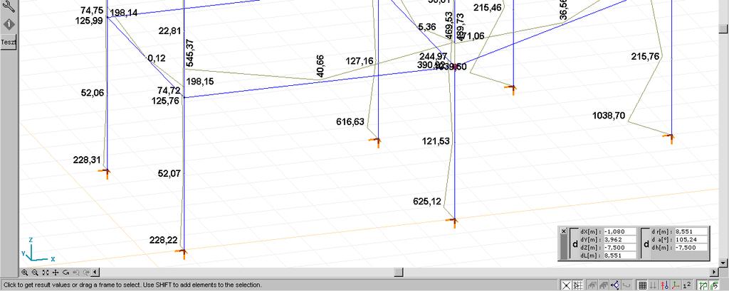
59 AxisVM 9 Verification Examples 59 Software Release Number: R2 Date: Tested by: InterCAD Page number: File name: Earthquake-01-EC.axs Thema Analysis Type Geometry Earth-quake design using response-spectrum method. Linear frequency analysis with 5 modes. Linear static analysis. Code : Eurocode Case : FR + 5,000 90,0 5,196 90,0 6,000 30,0 8,000 7,000 Y X Top view Code : Eurocode Case : FR + 4,000 3,500 Z X Front view
60 AxisVM 9 Verification Examples 60 Code : Eurocode Case : ST1 All nodal masses are Mx=My=Mz= kg All beams 60x40 cm Inertia about vertical axis is multiplied by Node D All columns 60x40 cm Column B Column A Support C Y Z X Perspective view All supports are constrained in all directions. ex=ey=ez=fix=fiy=fiz=0 Section beams: 60x40 cm Ax=2400 cm2 Ay=2000 cm2 Az=2000 cm2 Ix= cm4 Iy= cm2 Iz= cm4 Section columns: 60x40 cm Ax=2400 cm2 Ay=2000 cm2 Az=2000 cm2 Ix= cm4 Iy= cm2 Iz= cm4 Loads Nodal masses on eight nodes. Mx=My=Mz= kg Model self-weight is excluded. Spectrum for X and Y direction of seismic action: T[s] S d 2,156 S d [m/s 2 ] 1 0 1, ,2000 2, ,6000 2, ,3000 0, ,0000 0, ,0000 0, ,150 0,709 0,300 2,0000 T[s] Boundary Conditions Material Properties Nodes at the columns bottom ends are constrained in all directions. ex=ey=ez=fix=fiy=fiz=0 C25/30 E=3050 kn/cm2 ν =0,2 ρ = 0
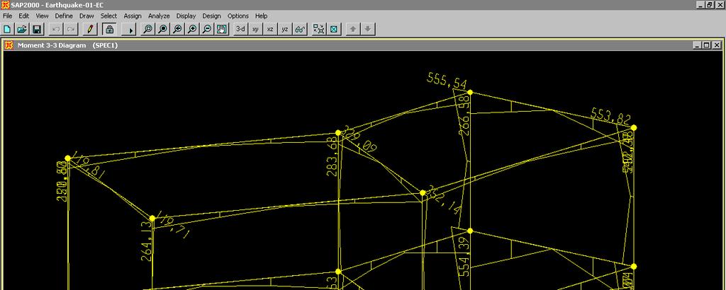
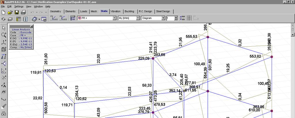
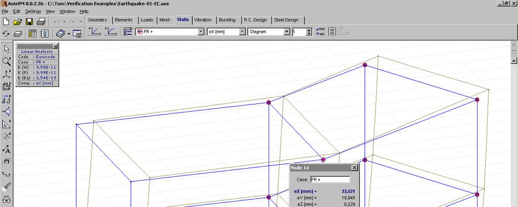
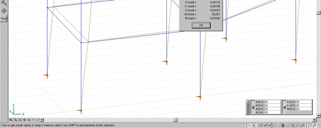
61 AxisVM 9 Verification Examples 61 Element types Target Results Three node straight prismatic beam element. Shear deformation is taken into account. Compare the model results with SAP2000 v6.13 results. The results are combined for all modes and all direction of spectral acceleration. CQC combination are used for modes in each direction of acceleration. SRSS combination are used for combination of directions. Period times of first 5 modes Mode T[s] SAP2000 T[s] AxisVM Difference [%] 1 0,7450 0, ,7099 0, ,3601 0, ,2314 0, ,2054 0, Modal participating mass ratios in X and Y directions Mode εx SAP2000 εx AxisVM Difference % εy SAP2000 εy AxisVM Difference % 1 0,5719 0, ,3153 0, ,03 2 0,3650 0, ,4761 0,4760-0, ,1261 0, ,0460 0, ,0131 0, ,0170 0, ,0562 0, Summ 1,0000 1, ,9868 0, Internal forces at the bottom end of Column A and Column B Column A SAP2000 Column A AxisVM Difference % Column B SAP2000 Column B AxisVM Difference % Nx [kn] 315,11 315,15 +0,01 557,26 557,29 +0,005 Vy [kn] 280,34 280, ,88 232,88 0 Vz [kn] 253,49 253, ,04 412,04 0 Tx [knm] 34,42 34,41-0,03 34,47 34,46-0,03 My [knm] 625,13 625,12-0, , ,70-0,004 Mz [knm] 612,31 612, ,41 553,41 0 Support forces of Support C Support C SAP2000 Support C AxisVM Difference % Rx [kn] 280,34 280,34 0 Ry [kn] 253,49 253,49 0 Rz [kn] 315,11 315,15 +0,01 Rxx [knm] 625,13 625,12-0,002 Ryy [knm] 612,31 612,31 0 Rzz [knm] 34,42 34,41-0,03 Displacements of Node D Node D SAP2000 Node D AxisVM Difference % ex [mm] 33,521 33,521 0 ey [mm] 19,944 19,945 +0,005 ez [mm] 0,229 0,229 0 ϕx [rad] 0, , ϕy [rad] 0, , ϕz [rad] 0, ,
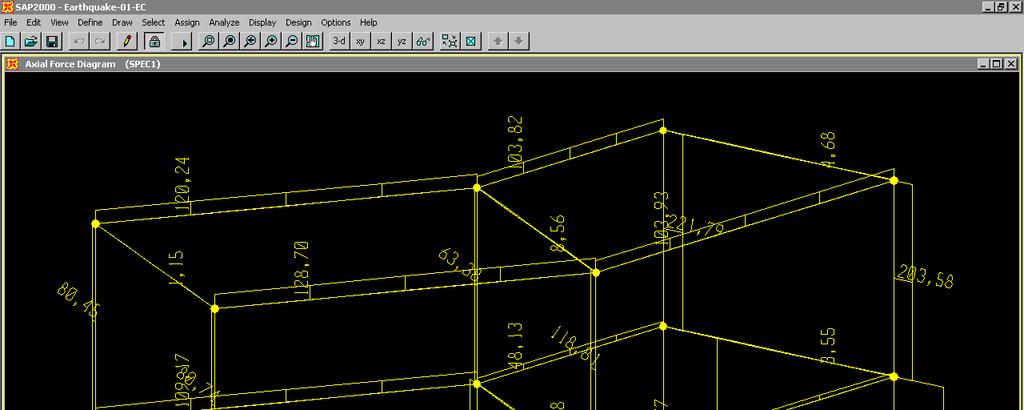
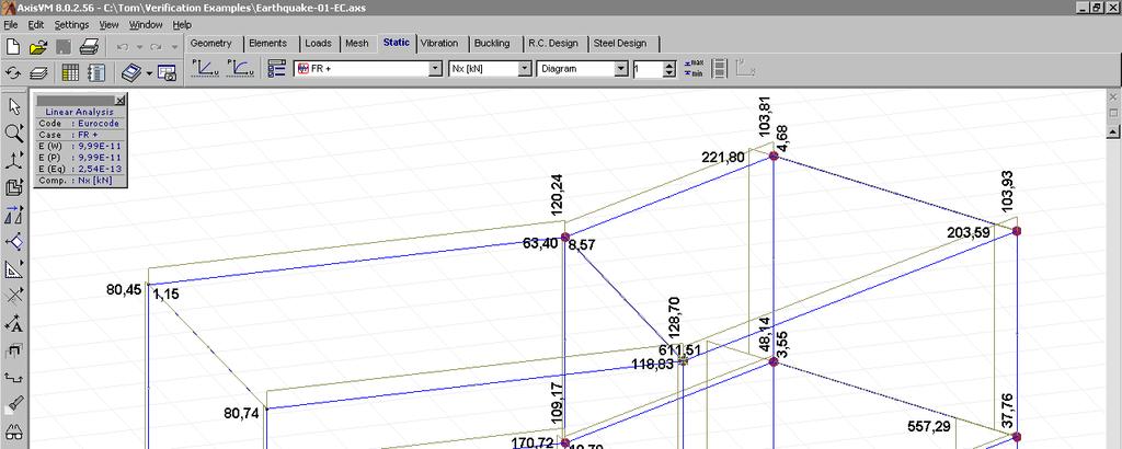
62 AxisVM 9 Verification Examples 62 Normal forces:


63 AxisVM 9 Verification Examples 63 Bending moments:
64 AxisVM 9 Verification Examples 64
65 AxisVM 9 Verification Examples 65 Displacements:
Verification Examples
 Verification Examples 01 AxisVM 11 Verification Examples Linear static...3 Supported bar with concentrated loads....4 Thermally loaded bar structure...5 Continously supported beam with constant distributed
Verification Examples
 Verification Examples 015 AxisVM 13 Verification Examples Linear static... 3 Supported bar with concentrated loads.... 4 Thermally loaded bar structure.... 5 Continously supported beam with constant distributed
Verification Examples
 Verification Examples 018 AxisVM X4 Verification Examples Linear static... 4 Supported bar with concentrated loads.... 5 Thermally loaded bar structure.... 6 Continously supported beam with point loads....
Verification Examples. FEM-Design. version
 FEM-Design 6.0 FEM-Design version. 06 FEM-Design 6.0 StruSoft AB Visit the StruSoft website for company and FEM-Design information at www.strusoft.com Copyright 06 by StruSoft, all rights reserved. Trademarks
Software Verification
 EXAMPLE 16 racked Slab Analysis RAKED ANALYSIS METHOD The moment curvature diagram shown in Figure 16-1 depicts a plot of the uncracked and cracked conditions, Ψ 1 State 1, and, Ψ State, for a reinforced
D : SOLID MECHANICS. Q. 1 Q. 9 carry one mark each.
 GTE 2016 Q. 1 Q. 9 carry one mark each. D : SOLID MECHNICS Q.1 single degree of freedom vibrating system has mass of 5 kg, stiffness of 500 N/m and damping coefficient of 100 N-s/m. To make the system
Static & Dynamic. Analysis of Structures. Edward L.Wilson. University of California, Berkeley. Fourth Edition. Professor Emeritus of Civil Engineering
 Static & Dynamic Analysis of Structures A Physical Approach With Emphasis on Earthquake Engineering Edward LWilson Professor Emeritus of Civil Engineering University of California, Berkeley Fourth Edition
Software Verification
 PROGRAM NAME: SAFE 014 EXAMPLE 16 racked Slab Analysis RAKED ANALYSIS METHOD The moment curvature diagram shown in Figure 16-1 depicts a plot of the uncracked and cracked conditions, 1 State 1, and, State,
Analytical Strip Method for Thin Isotropic Cylindrical Shells
 IOSR Journal of Mechanical and Civil Engineering (IOSR-JMCE) e-issn: 2278-1684,p-ISSN: 2320-334X, Volume 14, Issue 4 Ver. III (Jul. Aug. 2017), PP 24-38 www.iosrjournals.org Analytical Strip Method for
Workshop 8. Lateral Buckling
 Workshop 8 Lateral Buckling cross section A transversely loaded member that is bent about its major axis may buckle sideways if its compression flange is not laterally supported. The reason buckling occurs
BE Semester- I ( ) Question Bank (MECHANICS OF SOLIDS)
 Question Bank (MECHANICS OF SOLIDS)") BE Semester- I ( ) Question Bank (MECHANICS OF SOLIDS) All questions carry equal marks(10 marks) Q.1 (a) Write the SI units of following quantities and also mention whether it is scalar or vector: (i)
BE Semester- I ( ) Question Bank (MECHANICS OF SOLIDS) All questions carry equal marks(10 marks) Q.1 (a) Write the SI units of following quantities and also mention whether it is scalar or vector: (i)
UNIVERSITY OF SASKATCHEWAN ME MECHANICS OF MATERIALS I FINAL EXAM DECEMBER 13, 2008 Professor A. Dolovich
 UNIVERSITY OF SASKATCHEWAN ME 313.3 MECHANICS OF MATERIALS I FINAL EXAM DECEMBER 13, 2008 Professor A. Dolovich A CLOSED BOOK EXAMINATION TIME: 3 HOURS For Marker s Use Only LAST NAME (printed): FIRST
CHAPTER 14 BUCKLING ANALYSIS OF 1D AND 2D STRUCTURES
 CHAPTER 14 BUCKLING ANALYSIS OF 1D AND 2D STRUCTURES 14.1 GENERAL REMARKS In structures where dominant loading is usually static, the most common cause of the collapse is a buckling failure. Buckling may
D : SOLID MECHANICS. Q. 1 Q. 9 carry one mark each. Q.1 Find the force (in kn) in the member BH of the truss shown.
 in the member BH of the truss shown.") D : SOLID MECHANICS Q. 1 Q. 9 carry one mark each. Q.1 Find the force (in kn) in the member BH of the truss shown. Q.2 Consider the forces of magnitude F acting on the sides of the regular hexagon having
D : SOLID MECHANICS Q. 1 Q. 9 carry one mark each. Q.1 Find the force (in kn) in the member BH of the truss shown. Q.2 Consider the forces of magnitude F acting on the sides of the regular hexagon having
Design of reinforced concrete sections according to EN and EN
 Design of reinforced concrete sections according to EN 1992-1-1 and EN 1992-2 Validation Examples Brno, 21.10.2010 IDEA RS s.r.o. South Moravian Innovation Centre, U Vodarny 2a, 616 00 BRNO tel.: +420-511
Chapter 4 Analysis of a cantilever
 Chapter 4 Analysis of a cantilever Before a complex structure is studied performing a seismic analysis, the behaviour of simpler ones should be fully understood. To achieve this knowledge we will start
UNIT-I STRESS, STRAIN. 1. A Member A B C D is subjected to loading as shown in fig determine the total elongation. Take E= 2 x10 5 N/mm 2
 UNIT-I STRESS, STRAIN 1. A Member A B C D is subjected to loading as shown in fig determine the total elongation. Take E= 2 x10 5 N/mm 2 Young s modulus E= 2 x10 5 N/mm 2 Area1=900mm 2 Area2=400mm 2 Area3=625mm
Assignment 1 - actions
 Assignment 1 - actions b = 1,5 m a = 1 q kn/m 2 Determine action on the beam for verification of the ultimate limit state. Axial distance of the beams is 1 to 2 m, cross section dimensions 0,45 0,20 m
ME 1401 FINITE ELEMENT ANALYSIS UNIT I PART -A. 2. Why polynomial type of interpolation functions is mostly used in FEM?
 SHRI ANGALAMMAN COLLEGE OF ENGINEERING AND TECHNOLOGY (An ISO 9001:2008 Certified Institution) SIRUGANOOR, TIRUCHIRAPPALLI 621 105 Department of Mechanical Engineering ME 1401 FINITE ELEMENT ANALYSIS 1.
The University of Melbourne Engineering Mechanics
 The University of Melbourne 436-291 Engineering Mechanics Tutorial Four Poisson s Ratio and Axial Loading Part A (Introductory) 1. (Problem 9-22 from Hibbeler - Statics and Mechanics of Materials) A short
FINAL EXAMINATION. (CE130-2 Mechanics of Materials)
") UNIVERSITY OF CLIFORNI, ERKELEY FLL SEMESTER 001 FINL EXMINTION (CE130- Mechanics of Materials) Problem 1: (15 points) pinned -bar structure is shown in Figure 1. There is an external force, W = 5000N,
UNIVERSITY OF CLIFORNI, ERKELEY FLL SEMESTER 001 FINL EXMINTION (CE130- Mechanics of Materials) Problem 1: (15 points) pinned -bar structure is shown in Figure 1. There is an external force, W = 5000N,
Esben Byskov. Elementary Continuum. Mechanics for Everyone. With Applications to Structural Mechanics. Springer
 Esben Byskov Elementary Continuum Mechanics for Everyone With Applications to Structural Mechanics Springer Contents Preface v Contents ix Introduction What Is Continuum Mechanics? "I Need Continuum Mechanics
External Work. When a force F undergoes a displacement dx in the same direction i as the force, the work done is
 Structure Analysis I Chapter 9 Deflection Energy Method External Work Energy Method When a force F undergoes a displacement dx in the same direction i as the force, the work done is du e = F dx If the
ME 475 Modal Analysis of a Tapered Beam
 ME 475 Modal Analysis of a Tapered Beam Objectives: 1. To find the natural frequencies and mode shapes of a tapered beam using FEA.. To compare the FE solution to analytical solutions of the vibratory
VORONOI APPLIED ELEMENT METHOD FOR STRUCTURAL ANALYSIS: THEORY AND APPLICATION FOR LINEAR AND NON-LINEAR MATERIALS
 The 4 th World Conference on Earthquake Engineering October -7, 008, Beijing, China VORONOI APPLIED ELEMENT METHOD FOR STRUCTURAL ANALYSIS: THEORY AND APPLICATION FOR LINEAR AND NON-LINEAR MATERIALS K.
A METHOD OF LOAD INCREMENTS FOR THE DETERMINATION OF SECOND-ORDER LIMIT LOAD AND COLLAPSE SAFETY OF REINFORCED CONCRETE FRAMED STRUCTURES
 A METHOD OF LOAD INCREMENTS FOR THE DETERMINATION OF SECOND-ORDER LIMIT LOAD AND COLLAPSE SAFETY OF REINFORCED CONCRETE FRAMED STRUCTURES Konuralp Girgin (Ph.D. Thesis, Institute of Science and Technology,
4.4 1) 단순지지된깊은보 선형동적해석검증예제 ANALYSIS REFERENCE. REFERENCE NAFEMS 1 Beam elements, solid elements
 단순지지된깊은보 선형동적해석검증예제 ANALYSIS REFERENCE. REFERENCE NAFEMS 1 Beam elements, solid elements") 그림 5.4.3 가진방향에따른응답변화예시 Reaction Sum. Total Strain Energy 0 30 60 90 120 150 180 Excitation ngle 4.4 선형동적해석검증예제 1) 단순지지된깊은보 REFERENCE NFEMS 1 ELEMENTS Beam elements, solid elements MODEL FILENME LinearDynamic01.mpb
그림 5.4.3 가진방향에따른응답변화예시 Reaction Sum. Total Strain Energy 0 30 60 90 120 150 180 Excitation ngle 4.4 선형동적해석검증예제 1) 단순지지된깊은보 REFERENCE NFEMS 1 ELEMENTS Beam elements, solid elements MODEL FILENME LinearDynamic01.mpb
PRACTICE 2 PROYECTO Y CONSTRUCCIÓN DE PUENTES. 1º Máster Ingeniería de Caminos. E.T.S.I. Caminos, canales y puertos (Ciudad Real) 01/06/2016
 01/06/2016") PRACTICE 2 PROYECTO Y CONSTRUCCIÓN DE PUENTES 1º Máster Ingeniería de Caminos E.T.S.I. Caminos, canales y puertos (Ciudad Real) 01/06/2016 AUTHOR: CONTENT 1. INTRODUCTION... 3 2. BRIDGE GEOMETRY AND MATERIAL...
PRACTICE 2 PROYECTO Y CONSTRUCCIÓN DE PUENTES 1º Máster Ingeniería de Caminos E.T.S.I. Caminos, canales y puertos (Ciudad Real) 01/06/2016 AUTHOR: CONTENT 1. INTRODUCTION... 3 2. BRIDGE GEOMETRY AND MATERIAL...
Name :. Roll No. :... Invigilator s Signature :.. CS/B.TECH (CE-NEW)/SEM-3/CE-301/ SOLID MECHANICS
/SEM-3/CE-301/ SOLID MECHANICS") Name :. Roll No. :..... Invigilator s Signature :.. 2011 SOLID MECHANICS Time Allotted : 3 Hours Full Marks : 70 The figures in the margin indicate full marks. Candidates are required to give their answers
Name :. Roll No. :..... Invigilator s Signature :.. 2011 SOLID MECHANICS Time Allotted : 3 Hours Full Marks : 70 The figures in the margin indicate full marks. Candidates are required to give their answers
Structural Dynamics Lecture Eleven: Dynamic Response of MDOF Systems: (Chapter 11) By: H. Ahmadian
 By: H. Ahmadian") Structural Dynamics Lecture Eleven: Dynamic Response of MDOF Systems: (Chapter 11) By: H. Ahmadian ahmadian@iust.ac.ir Dynamic Response of MDOF Systems: Mode-Superposition Method Mode-Superposition Method:
Structural Dynamics Lecture Eleven: Dynamic Response of MDOF Systems: (Chapter 11) By: H. Ahmadian ahmadian@iust.ac.ir Dynamic Response of MDOF Systems: Mode-Superposition Method Mode-Superposition Method:
Semiloof Curved Thin Shell Elements
 Semiloof Curved Thin Shell Elements General Element Name Y,v,θy X,u,θx Z,w,θz Element Group Element Subgroup Element Description Number Of Nodes Freedoms Node Coordinates TSL 1 2 Semiloof 3 QSL8 7 8 1
prepared checked approved Date: Date: Date: S. Fahrendholz/R.Geiger Dr.-Ing. Jürgen Bellmann Dr.-Ing.
 Verification Manual Version 12.2 2009 prepared checked approved Date: 01.08.2003 Date: 19.01.2009 Date: 22.01.2009 S. Fahrendholz/R.Geiger Dr.Ing. Jürgen Bellmann Dr.Ing. Casimir Katz Document name: q:\dok\qs\verification.doc
2. Determine the deflection at C of the beam given in fig below. Use principal of virtual work. W L/2 B A L C
 CE-1259, Strength of Materials UNIT I STRESS, STRAIN DEFORMATION OF SOLIDS Part -A 1. Define strain energy density. 2. State Maxwell s reciprocal theorem. 3. Define proof resilience. 4. State Castigliano
7 Vlasov torsion theory
 7 Vlasov torsion theory P.C.J. Hoogenboom, October 006 Restrained Warping The typical torsion stresses according to De Saint Venant only occur if warping can take place freely (Fig. 1). In engineering
Response Spectrum Analysis Shock and Seismic. FEMAP & NX Nastran
 Response Spectrum Analysis Shock and Seismic FEMAP & NX Nastran Table of Contents 1. INTRODUCTION... 3 2. THE ACCELEROGRAM... 4 3. CREATING A RESPONSE SPECTRUM... 5 4. NX NASTRAN METHOD... 8 5. RESPONSE
CHAPTER 6: Shearing Stresses in Beams
 (130) CHAPTER 6: Shearing Stresses in Beams When a beam is in pure bending, the only stress resultants are the bending moments and the only stresses are the normal stresses acting on the cross sections.
Downloaded from Downloaded from / 1
 PURWANCHAL UNIVERSITY III SEMESTER FINAL EXAMINATION-2002 LEVEL : B. E. (Civil) SUBJECT: BEG256CI, Strength of Material Full Marks: 80 TIME: 03:00 hrs Pass marks: 32 Candidates are required to give their
Seismic design of bridges
 NATIONAL TECHNICAL UNIVERSITY OF ATHENS LABORATORY FOR EARTHQUAKE ENGINEERING Seismic design of bridges Lecture 3 Ioannis N. Psycharis Capacity design Purpose To design structures of ductile behaviour
STATIC NONLINEAR ANALYSIS. Advanced Earthquake Engineering CIVIL-706. Instructor: Lorenzo DIANA, PhD
 STATIC NONLINEAR ANALYSIS Advanced Earthquake Engineering CIVIL-706 Instructor: Lorenzo DIANA, PhD 1 By the end of today s course You will be able to answer: What are NSA advantages over other structural
GATE SOLUTIONS E N G I N E E R I N G
 GATE SOLUTIONS C I V I L E N G I N E E R I N G From (1987-018) Office : F-16, (Lower Basement), Katwaria Sarai, New Delhi-110016 Phone : 011-65064 Mobile : 81309090, 9711853908 E-mail: info@iesmasterpublications.com,
KINGS COLLEGE OF ENGINEERING DEPARTMENT OF MECHANICAL ENGINEERING QUESTION BANK. Subject code/name: ME2254/STRENGTH OF MATERIALS Year/Sem:II / IV
 KINGS COLLEGE OF ENGINEERING DEPARTMENT OF MECHANICAL ENGINEERING QUESTION BANK Subject code/name: ME2254/STRENGTH OF MATERIALS Year/Sem:II / IV UNIT I STRESS, STRAIN DEFORMATION OF SOLIDS PART A (2 MARKS)
Optimum Height of Plate Stiffener under Pressure Effect
 The st Regional Conference of Eng. Sci. NUCEJ Spatial ISSUE vol., No.3, 8 pp 459-468 Optimum Height of Plate Stiffener under Pressure Effect Mazin Victor Yousif M.Sc Production Engineering University of
Sabah Shawkat Cabinet of Structural Engineering Walls carrying vertical loads should be designed as columns. Basically walls are designed in
 Sabah Shawkat Cabinet of Structural Engineering 17 3.6 Shear walls Walls carrying vertical loads should be designed as columns. Basically walls are designed in the same manner as columns, but there are
Due Tuesday, September 21 st, 12:00 midnight
 Due Tuesday, September 21 st, 12:00 midnight The first problem discusses a plane truss with inclined supports. You will need to modify the MatLab software from homework 1. The next 4 problems consider
CE5510 Advanced Structural Concrete Design - Design & Detailing of Openings in RC Flexural Members-
 CE5510 Advanced Structural Concrete Design - Design & Detailing Openings in RC Flexural Members- Assoc Pr Tan Kiang Hwee Department Civil Engineering National In this lecture DEPARTMENT OF CIVIL ENGINEERING
Stress Analysis Lecture 3 ME 276 Spring Dr./ Ahmed Mohamed Nagib Elmekawy
 Stress Analysis Lecture 3 ME 276 Spring 2017-2018 Dr./ Ahmed Mohamed Nagib Elmekawy Axial Stress 2 Beam under the action of two tensile forces 3 Beam under the action of two tensile forces 4 Shear Stress
Engineering Science OUTCOME 1 - TUTORIAL 4 COLUMNS
 Unit 2: Unit code: QCF Level: Credit value: 15 Engineering Science L/601/10 OUTCOME 1 - TUTORIAL COLUMNS 1. Be able to determine the behavioural characteristics of elements of static engineering systems
Mechanics of Materials II. Chapter III. A review of the fundamental formulation of stress, strain, and deflection
 Mechanics of Materials II Chapter III A review of the fundamental formulation of stress, strain, and deflection Outline Introduction Assumtions and limitations Axial loading Torsion of circular shafts
3. Stability of built-up members in compression
 3. Stability of built-up members in compression 3.1 Definitions Build-up members, made out by coupling two or more simple profiles for obtaining stronger and stiffer section are very common in steel structures,
The Finite Element Method for Solid and Structural Mechanics
 The Finite Element Method for Solid and Structural Mechanics Sixth edition O.C. Zienkiewicz, CBE, FRS UNESCO Professor of Numerical Methods in Engineering International Centre for Numerical Methods in
Civil Engineering Design (1) Design of Reinforced Concrete Columns 2006/7
 Design of Reinforced Concrete Columns 2006/7") Civil Engineering Design (1) Design of Reinforced Concrete Columns 2006/7 Dr. Colin Caprani, Chartered Engineer 1 Contents 1. Introduction... 3 1.1 Background... 3 1.2 Failure Modes... 5 1.3 Design Aspects...
Civil Engineering Design (1) Design of Reinforced Concrete Columns 2006/7 Dr. Colin Caprani, Chartered Engineer 1 Contents 1. Introduction... 3 1.1 Background... 3 1.2 Failure Modes... 5 1.3 Design Aspects...
 UNIT III DEFLECTION OF BEAMS 1. What are the methods for finding out the slope and deflection at a section? The important methods used for finding out the slope and deflection at a section in a loaded
Level 7 Postgraduate Diploma in Engineering Computational mechanics using finite element method
 9210-203 Level 7 Postgraduate Diploma in Engineering Computational mechanics using finite element method You should have the following for this examination one answer book No additional data is attached
FIXED BEAMS IN BENDING
 FIXED BEAMS IN BENDING INTRODUCTION Fixed or built-in beams are commonly used in building construction because they possess high rigidity in comparison to simply supported beams. When a simply supported
DETAILED SYLLABUS FOR DISTANCE EDUCATION. Diploma. (Three Years Semester Scheme) Diploma in Architecture (DARC)
 Diploma in Architecture (DARC)") DETAILED SYLLABUS FOR DISTANCE EDUCATION Diploma (Three Years Semester Scheme) Diploma in Architecture (DARC) COURSE TITLE DURATION : Diploma in ARCHITECTURE (DARC) : 03 Years (Semester System) FOURTH
DETAILED SYLLABUS FOR DISTANCE EDUCATION Diploma (Three Years Semester Scheme) Diploma in Architecture (DARC) COURSE TITLE DURATION : Diploma in ARCHITECTURE (DARC) : 03 Years (Semester System) FOURTH
ENG2000 Chapter 7 Beams. ENG2000: R.I. Hornsey Beam: 1
 ENG2000 Chapter 7 Beams ENG2000: R.I. Hornsey Beam: 1 Overview In this chapter, we consider the stresses and moments present in loaded beams shear stress and bending moment diagrams We will also look at
Bending of Simply Supported Isotropic and Composite Laminate Plates
 Bending of Simply Supported Isotropic and Composite Laminate Plates Ernesto Gutierrez-Miravete 1 Isotropic Plates Consider simply a supported rectangular plate of isotropic material (length a, width b,
ε t increases from the compressioncontrolled Figure 9.15: Adjusted interaction diagram
 CHAPTER NINE COLUMNS 4 b. The modified axial strength in compression is reduced to account for accidental eccentricity. The magnitude of axial force evaluated in step (a) is multiplied by 0.80 in case
SN QUESTION YEAR MARK 1. State and prove the relationship between shearing stress and rate of change of bending moment at a section in a loaded beam.
 ALPHA COLLEGE OF ENGINEERING AND TECHNOLOGY DEPARTMENT OF MECHANICAL ENGINEERING MECHANICS OF SOLIDS (21000) ASSIGNMENT 1 SIMPLE STRESSES AND STRAINS SN QUESTION YEAR MARK 1 State and prove the relationship
If you take CT5143 instead of CT4143 then write this at the first of your answer sheets and skip problem 4 and 6.
 Delft University of Technology Faculty of Civil Engineering and Geosciences Structural Mechanics Section Write your name and study number at the top right-hand of your work. Exam CT4143 Shell Analysis
Table of Contents. Preface...xvii. Part 1. Level
 Preface...xvii Part 1. Level 1... 1 Chapter 1. The Basics of Linear Elastic Behavior... 3 1.1. Cohesion forces... 4 1.2. The notion of stress... 6 1.2.1. Definition... 6 1.2.2. Graphical representation...
SERVICEABILITY LIMIT STATE DESIGN
 CHAPTER 11 SERVICEABILITY LIMIT STATE DESIGN Article 49. Cracking Limit State 49.1 General considerations In the case of verifications relating to Cracking Limit State, the effects of actions comprise
Q. 1 Q. 5 carry one mark each.
 General ptitude G Set-8 Q. 1 Q. 5 carry one mark each. Q.1 The chairman requested the aggrieved shareholders to him. () bare with () bore with (C) bear with (D) bare Q.2 Identify the correct spelling out
A Parametric Study on Lateral Torsional Buckling of European IPN and IPE Cantilevers H. Ozbasaran
 Vol:8, No:7, 214 A Parametric Study on Lateral Torsional Buckling of European IPN and IPE Cantilevers H. Ozbasaran Abstract IPN and IPE sections, which are commonly used European I shapes, are widely used
Civil Engineering Design (1) Analysis and Design of Slabs 2006/7
 Analysis and Design of Slabs 2006/7") Civil Engineering Design (1) Analysis and Design of Slabs 006/7 Dr. Colin Caprani, Chartered Engineer 1 Contents 1. Elastic Methods... 3 1.1 Introduction... 3 1. Grillage Analysis... 4 1.3 Finite Element
Civil Engineering Design (1) Analysis and Design of Slabs 006/7 Dr. Colin Caprani, Chartered Engineer 1 Contents 1. Elastic Methods... 3 1.1 Introduction... 3 1. Grillage Analysis... 4 1.3 Finite Element
3D Semiloof Thin Beam Elements
 3D Semiloof Thin Beam Elements General Element Name Z,w,θz Y,v,θy Element Group X,u,θx Element Subgroup Element Description Number Of Nodes BSL3, BSL4 y 1 4 x z 2 Semiloof 3 Curved beam elements in 3D
CHAPTER 4: BENDING OF BEAMS
 (74) CHAPTER 4: BENDING OF BEAMS This chapter will be devoted to the analysis of prismatic members subjected to equal and opposite couples M and M' acting in the same longitudinal plane. Such members are
Iraq Ref. & Air. Cond. Dept/ Technical College / Kirkuk
 International Journal of Scientific & Engineering Research, Volume 6, Issue 4, April-015 1678 Study the Increasing of the Cantilever Plate Stiffness by Using s Jawdat Ali Yakoob Iesam Jondi Hasan Ass.
SRI CHANDRASEKHARENDRA SARASWATHI VISWA MAHAVIDHYALAYA
 SRI CHANDRASEKHARENDRA SARASWATHI VISWA MAHAVIDHYALAYA (Declared as Deemed-to-be University under Section 3 of the UGC Act, 1956, Vide notification No.F.9.9/92-U-3 dated 26 th May 1993 of the Govt. of
9.5 Compression Members
 9.5 Compression Members This section covers the following topics. Introduction Analysis Development of Interaction Diagram Effect of Prestressing Force 9.5.1 Introduction Prestressing is meaningful when
QUESTION BANK DEPARTMENT: CIVIL SEMESTER: III SUBJECT CODE: CE2201 SUBJECT NAME: MECHANICS OF SOLIDS UNIT 1- STRESS AND STRAIN PART A
 DEPARTMENT: CIVIL SUBJECT CODE: CE2201 QUESTION BANK SEMESTER: III SUBJECT NAME: MECHANICS OF SOLIDS UNIT 1- STRESS AND STRAIN PART A (2 Marks) 1. Define longitudinal strain and lateral strain. 2. State
Institute of Structural Engineering Page 1. Method of Finite Elements I. Chapter 2. The Direct Stiffness Method. Method of Finite Elements I
 Institute of Structural Engineering Page 1 Chapter 2 The Direct Stiffness Method Institute of Structural Engineering Page 2 Direct Stiffness Method (DSM) Computational method for structural analysis Matrix
JEPPIAAR ENGINEERING COLLEGE
 JEPPIAAR ENGINEERING COLLEGE Jeppiaar Nagar, Rajiv Gandhi Salai 600 119 DEPARTMENT OFMECHANICAL ENGINEERING QUESTION BANK VI SEMESTER ME6603 FINITE ELEMENT ANALYSIS Regulation 013 SUBJECT YEAR /SEM: III
Chapter 5 CENTRIC TENSION OR COMPRESSION ( AXIAL LOADING )
") Chapter 5 CENTRIC TENSION OR COMPRESSION ( AXIAL LOADING ) 5.1 DEFINITION A construction member is subjected to centric (axial) tension or compression if in any cross section the single distinct stress
Chapter 5 CENTRIC TENSION OR COMPRESSION ( AXIAL LOADING ) 5.1 DEFINITION A construction member is subjected to centric (axial) tension or compression if in any cross section the single distinct stress
Using MATLAB and. Abaqus. Finite Element Analysis. Introduction to. Amar Khennane. Taylor & Francis Croup. Taylor & Francis Croup,
 Introduction to Finite Element Analysis Using MATLAB and Abaqus Amar Khennane Taylor & Francis Croup Boca Raton London New York CRC Press is an imprint of the Taylor & Francis Croup, an informa business
2012 MECHANICS OF SOLIDS
 R10 SET - 1 II B.Tech II Semester, Regular Examinations, April 2012 MECHANICS OF SOLIDS (Com. to ME, AME, MM) Time: 3 hours Max. Marks: 75 Answer any FIVE Questions All Questions carry Equal Marks ~~~~~~~~~~~~~~~~~~~~~~
UNIT- I Thin plate theory, Structural Instability:
 UNIT- I Thin plate theory, Structural Instability: Analysis of thin rectangular plates subject to bending, twisting, distributed transverse load, combined bending and in-plane loading Thin plates having
TABLE OF CONTENTS SECTION TITLE PAGE 2 PRINCIPLES OF SEISMIC ISOLATION OF BRIDGES 3
 TABLE OF CONTENTS SECTION TITLE PAGE 1 INTRODUCTION 1 2 PRINCIPLES OF SEISMIC ISOLATION OF BRIDGES 3 3 ANALYSIS METHODS OF SEISMICALLY ISOLATED BRIDGES 5 3.1 Introduction 5 3.2 Loadings for the Analysis
MTE 119 STATICS FINAL HELP SESSION REVIEW PROBLEMS PAGE 1 9 NAME & ID DATE. Example Problem P.1
 MTE STATICS Example Problem P. Beer & Johnston, 004 by Mc Graw-Hill Companies, Inc. The structure shown consists of a beam of rectangular cross section (4in width, 8in height. (a Draw the shear and bending
Design of AAC wall panel according to EN 12602
 Design of wall panel according to EN 160 Example 3: Wall panel with wind load 1.1 Issue Design of a wall panel at an industrial building Materials with a compressive strength 3,5, density class 500, welded
INELASTIC SEISMIC DISPLACEMENT RESPONSE PREDICTION OF MDOF SYSTEMS BY EQUIVALENT LINEARIZATION
 INEASTIC SEISMIC DISPACEMENT RESPONSE PREDICTION OF MDOF SYSTEMS BY EQUIVAENT INEARIZATION M. S. Günay 1 and H. Sucuoğlu 1 Research Assistant, Dept. of Civil Engineering, Middle East Technical University,
CRACK FORMATION AND CRACK PROPAGATION INTO THE COMPRESSION ZONE ON REINFORCED CONCRETE BEAM STRUCTURES
 S. Kakay et al. Int. J. Comp. Meth. and Exp. Meas. Vol. 5 No. (017) 116 14 CRACK FORMATION AND CRACK PROPAGATION INTO THE COMPRESSION ZONE ON REINFORCED CONCRETE BEAM STRUCTURES SAMDAR KAKAY DANIEL BÅRDSEN
BOOK OF COURSE WORKS ON STRENGTH OF MATERIALS FOR THE 2 ND YEAR STUDENTS OF THE UACEG
 BOOK OF COURSE WORKS ON STRENGTH OF MATERIALS FOR THE ND YEAR STUDENTS OF THE UACEG Assoc.Prof. Dr. Svetlana Lilkova-Markova, Chief. Assist. Prof. Dimitar Lolov Sofia, 011 STRENGTH OF MATERIALS GENERAL
MARKS DISTRIBUTION AS PER CHAPTER (QUESTION ASKED IN GTU EXAM) Name Of Chapter. Applications of. Friction. Centroid & Moment.
 Name Of Chapter. Applications of. Friction. Centroid & Moment.") Introduction Fundamentals of statics Applications of fundamentals of statics Friction Centroid & Moment of inertia Simple Stresses & Strain Stresses in Beam Torsion Principle Stresses DEPARTMENT OF CIVIL
Introduction Fundamentals of statics Applications of fundamentals of statics Friction Centroid & Moment of inertia Simple Stresses & Strain Stresses in Beam Torsion Principle Stresses DEPARTMENT OF CIVIL
Some Aspects Of Dynamic Buckling of Plates Under In Plane Pulse Loading
 Mechanics and Mechanical Engineering Vol. 12, No. 2 (2008) 135 146 c Technical University of Lodz Some Aspects Of Dynamic Buckling of Plates Under In Plane Pulse Loading Katarzyna Kowal Michalska, Rados
SSC-JE MAINS ONLINE TEST SERIES / CIVIL ENGINEERING SOM + TOS
 SSC-JE MAINS ONLINE TEST SERIES / CIVIL ENGINEERING SOM + TOS Time Allowed:2 Hours Maximum Marks: 300 Attention: 1. Paper consists of Part A (Civil & Structural) Part B (Electrical) and Part C (Mechanical)
DYNAMIC RESPONSE OF THIN-WALLED GIRDERS SUBJECTED TO COMBINED LOAD
 DYNAMIC RESPONSE OF THIN-WALLED GIRDERS SUBJECTED TO COMBINED LOAD P. WŁUKA, M. URBANIAK, T. KUBIAK Department of Strength of Materials, Lodz University of Technology, Stefanowskiego 1/15, 90-924 Łódź,
BHAR AT HID AS AN ENGIN E ERI N G C O L L E G E NATTR A MPA LL I
 BHAR AT HID AS AN ENGIN E ERI N G C O L L E G E NATTR A MPA LL I 635 8 54. Third Year M E C H A NICAL VI S E M ES TER QUE S T I ON B ANK Subject: ME 6 603 FIN I T E E LE ME N T A N A L YSIS UNI T - I INTRODUCTION
1-1 Locate the centroid of the plane area shown. 1-2 Determine the location of centroid of the composite area shown.
 Chapter 1 Review of Mechanics of Materials 1-1 Locate the centroid of the plane area shown 650 mm 1000 mm 650 x 1- Determine the location of centroid of the composite area shown. 00 150 mm radius 00 mm
Review of Strain Energy Methods and Introduction to Stiffness Matrix Methods of Structural Analysis
 uke University epartment of Civil and Environmental Engineering CEE 42L. Matrix Structural Analysis Henri P. Gavin Fall, 22 Review of Strain Energy Methods and Introduction to Stiffness Matrix Methods
Shear Deformation Effect in Flexural-torsional Vibrations of Composite Beams by Boundary Element Method (BEM)
") Shear Deformation Effect in Flexural-torsional Vibrations of Composite Beams by Boundary Element Method (BEM) E. J. SAPOUNTZAKIS J. A. DOURAKOPOULOS School of Civil Engineering, National Technical University,
Shear Deformation Effect in Flexural-torsional Vibrations of Composite Beams by Boundary Element Method (BEM) E. J. SAPOUNTZAKIS J. A. DOURAKOPOULOS School of Civil Engineering, National Technical University,
EUROCODE EN SEISMIC DESIGN OF BRIDGES
 Brussels, 18-20 February 2008 Dissemination of information workshop 1 EUROCODE EN1998-2 SEISMIC DESIGN OF BRIDGES Basil Kolias Basic Requirements Brussels, 18-20 February 2008 Dissemination of information
Lecture 7: The Beam Element Equations.
 4.1 Beam Stiffness. A Beam: A long slender structural component generally subjected to transverse loading that produces significant bending effects as opposed to twisting or axial effects. MECH 40: Finite
PES Institute of Technology
 PES Institute of Technology Bangalore south campus, Bangalore-5460100 Department of Mechanical Engineering Faculty name : Madhu M Date: 29/06/2012 SEM : 3 rd A SEC Subject : MECHANICS OF MATERIALS Subject
Symmetric Bending of Beams
 Symmetric Bending of Beams beam is any long structural member on which loads act perpendicular to the longitudinal axis. Learning objectives Understand the theory, its limitations and its applications
Validation of SAFIR through DIN EN NA
 Validation of SAFIR through DIN EN 1992-1-2 NA Comparison of the results for the examples presented in Annex CC March 2018 J. Ferreira J.-M. Franssen T. Gernay A. Gamba University of Liege ArGEnCo Structural
Introduction to Continuous Systems. Continuous Systems. Strings, Torsional Rods and Beams.
 Outline of Continuous Systems. Introduction to Continuous Systems. Continuous Systems. Strings, Torsional Rods and Beams. Vibrations of Flexible Strings. Torsional Vibration of Rods. Bernoulli-Euler Beams.
3 Hours/100 Marks Seat No.
 *17304* 17304 14115 3 Hours/100 Marks Seat No. Instructions : (1) All questions are compulsory. (2) Illustrate your answers with neat sketches wherever necessary. (3) Figures to the right indicate full
Unit 13 Review of Simple Beam Theory
 MIT - 16.0 Fall, 00 Unit 13 Review of Simple Beam Theory Readings: Review Unified Engineering notes on Beam Theory BMP 3.8, 3.9, 3.10 T & G 10-15 Paul A. Lagace, Ph.D. Professor of Aeronautics & Astronautics
FINITE ELEMENT ANALYSIS OF TAPERED COMPOSITE PLATE GIRDER WITH A NON-LINEAR VARYING WEB DEPTH
 Journal of Engineering Science and Technology Vol. 12, No. 11 (2017) 2839-2854 School of Engineering, Taylor s University FINITE ELEMENT ANALYSIS OF TAPERED COMPOSITE PLATE GIRDER WITH A NON-LINEAR VARYING