P1: Basics - Things you now know that you didn t know you knew (25 pts)
|
|
|
- Edward Kennedy
- 5 years ago
- Views:
Transcription
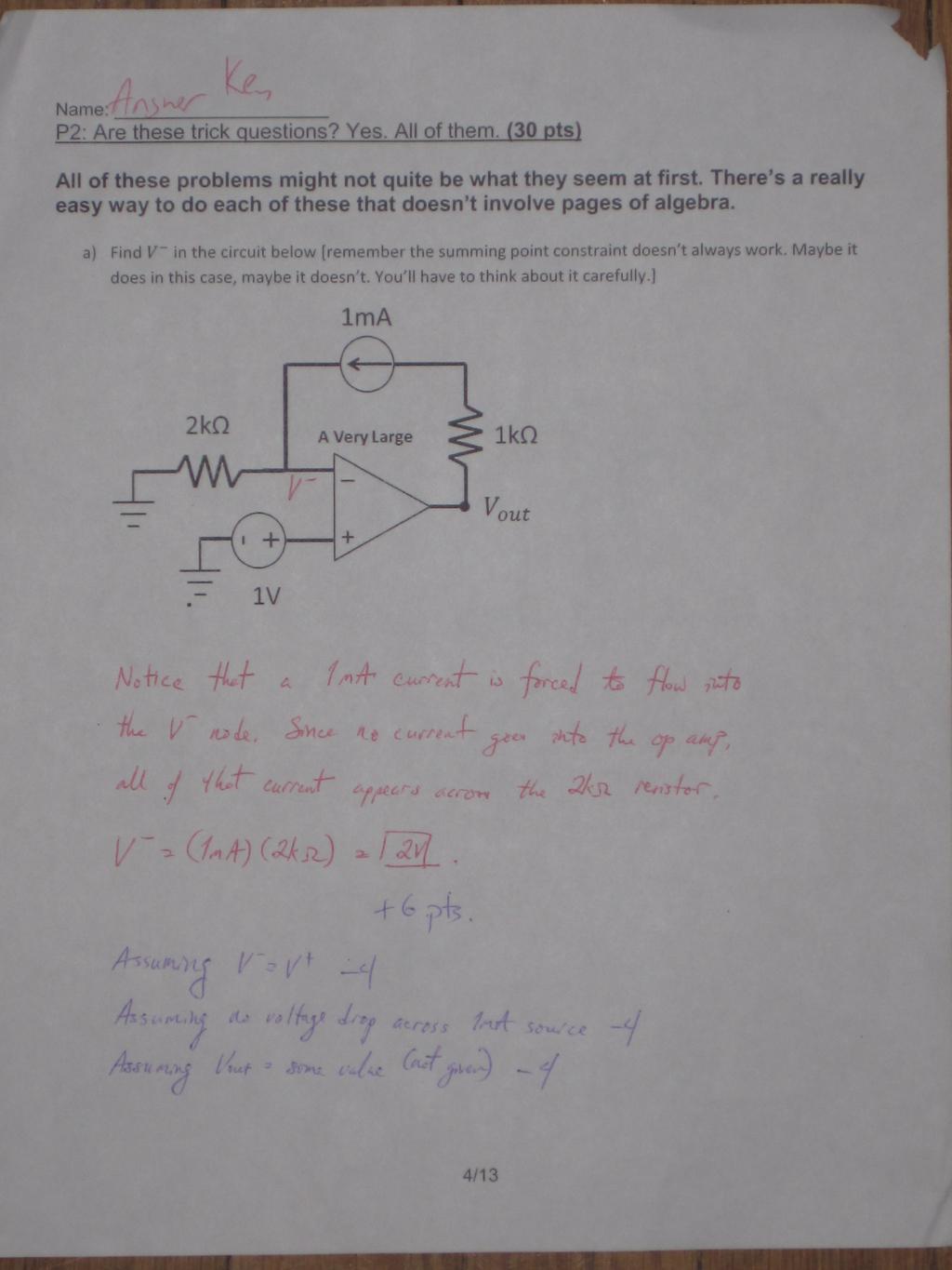
1 P1: Basics - Things you now know that you didn t know you knew (25 pts) a) Birds routinely land and relax on power lines which carry tens of thousands of volts of electricity. Explain why these birds do not get electrocuted. (6 pts) The resistance of the air is too large for current to flow from the line to the bird to the ground. Alternately, the resistance is too large for current to divert from the wire, into the bird, and then back into the wire. It is not because of wire insulation. Birds could land on uninsulated wires just fine. 6 pts for right answer. 1 pt for something vaguely correct. b) Suppose your car battery is dead, and you need to charge it using another car s battery. You have a pair of cables which you can use to connect the terminals of the batteries. In order to charge your car battery, should you connect the same terminals (positive of one battery to the positive of the other, and the same with the negative) or the opposite terminals (positive of one battery to the negative of the other battery)? Why did you choose this configuration? First note that real batteries have internal resistance, so the universe will not explode if you directly connect two car batteries. Sorry guys. Next, if the opposite terminals are connected, then P=VI and common sense tells us that both batteries will be supplying power, and the internal resistances will be consuming power, so clearly no power is being delivered by either battery. If the same terminals are connected, then we can see that if one battery is of a higher voltage than the other, it will provide power to the other battery. Key to this realization is to know that battery voltages drop as the battery is depleted. This was not discussed in class explicitly, but was hopefully clear. 6 pts for right answer. 2 pts if you try to say there is no current if two batteries are connected + to + because voltage sources are perfectly balanced. c) A standard procedure for testing the internal resistance of a battery is the dual pulse test. We first attach an ideal 5 ma current source between the terminals of the battery, so that current flows in the usual direction (positive to negative), and measure the voltage across the battery terminals. We then remove the 5 ma source, and attach an ideal 505 ma current source instead, and again measure the battery terminals. i. Suppose that we find a 1.485V voltage with the 5 ma source, and a with the 505 ma source, what is the internal resistance?
2 Name: There was a bug in the above diagram, current should have been flowing from + to as it says in the text! ( ) Easy way to solve these is to subtract 2 nd from first, giving, or. If you did this the other way around and got right answer. 2 pts if sign error or algebra mistake., then you are owed a point. 3 pts for ii. Assuming the battery is perfectly linear (i.e. accurately modeled by a Thevenin equivalent), is it possible to find the voltage provided by the battery with no load attached using the data above? If so, what is it? If not, why not? Plug in to one of our equations above, e.g., giving, or finally. If you did it with the current source the other way, you should still have gotten 1.486V. 3 pts for right answer. 2 pts if sign error or algebra mistake d) An EE40 student has constructed a purely resistive circuit which drains the connected battery too quickly. He decides to add another battery in parallel to fix the problem (assume internal resistance of the battery is not important). a. Will adding another battery in parallel actually reduce the power provided by each battery? For this problem, imagine replacing the resistive circuit in the middle with an equivalent resistor. In this case, each battery will provide only half the current that a single battery would provide (draw it if you re confused), and thus will use only half the power. 3 pts b. Will the load still receive the same total amount of current? Yes, because the voltage across the resistive circuit is still the same and so Ohm s Law tells us the current will be the same. 3 pts e) An EE40 student takes a random black box device (the contents of the box are unknown) and connects it to a 5V source. He finds that there is a 1A current and claims that the black box must contain only resistors, and that these resistors have a 5Ω equivalent resistance. Is the student right or wrong? If he is right, why? If he is wrong, give a specific counterexample of something else that might be in the box. No, for example, there could just be a 1A current source. 6 pts 2/3
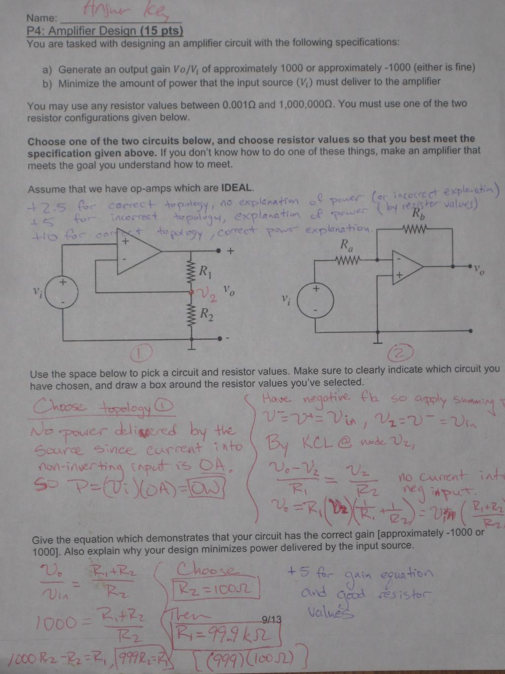
![Name: P3: Op-Amptimus Prime (25 pts) [still needs grade breakdown but I am falling asleeeep, so here s the answers just for now] a) Explain why it is safe to use the summing point constraint on the](/docs-images/92/108476826/images/3-1.jpg "op-amp on the right. We have negative feedback and a very large A. +5 pts b) Find and as a function of and. Assume that the input signals are small enough that the opamps do not saturate.")
3 Name: P3: Op-Amptimus Prime (25 pts) [still needs grade breakdown but I am falling asleeeep, so here s the answers just for now] a) Explain why it is safe to use the summing point constraint on the op-amp on the right. We have negative feedback and a very large A. +5 pts b) Find and as a function of and. Assume that the input signals are small enough that the opamps do not saturate. If you re not sure about, you can also give in terms of. is by definition of op-amps just ( )=2V 1 (+5 pts) (-2 for not getting V 1 in there) In the portion on the right, we have what looks mostly like an inverting amplifier, except that the + side is not grounded. We can see by inspection that. Thus, we know that. Then we have: Solving, we just get +10 pts c) If, and, how large must be before one of the op-amps saturates? Which op-amp will saturate first? (If you didn t get part b, you may assume for this sub-problem that [this is not the right answer to part b]) (+5 pts) Left saturates at 5V. On the right we have =. So obviously left op-amp will saturate first. 3/3
4
5
6
7
8
9
10
, have adapted to this new way of life. Rugged and tiring though it may be, you are all happy.")
 that it contains only resistors and linear sources.")

11 P6: The hard problem that I promised (25 pts) [Do this one last! It s much harder than the others] It is a grim post-apocalyptic future, but the survivors (you included), have adapted to this new way of life. Rugged and tiring though it may be, you are all happy. One day, you are brought a two terminal black box and it is extremely important to the future of the surviving members of the human race to know what is inside of this thing. Luckily, you know that (based on an old and faded but highly trustworthy label) that it contains only resistors and linear sources. Thus, you know you can find the Thevenin equivalent of the circuit inside by applying tests using your lab equipment. Piece of cake, you say, I ll measure the open circuit voltage and the short circuit current, and then I will enjoy the gratitude and praise of my fellow man! Unfortunately, a dastardly dude has stolen all of your measurement equipment, and you are left with only the following asinine measuring device, abandoned in a corner, dusty and almost forgotten, designed for purposes unfathomable by persons unknown. The device works as follows. It has two settings. In the first setting, it applies a voltage and gives you back the current through the 2Ω resistor, giving you. In the other setting, it completely disconnects the voltage source, and still gives you the current through the 2Ω resistor, giving you.

12 Name: You try the first setting and find that =1 ampere, and then when you try the other setting, you get that =1 ampere as well. Using this information, determine what is in the box. As announced in class, the bottom right resistor should be 1Ω. Since the black box can be written as a Thevenin equivalent, we should replace the black box with a Thevenin circuit to make things more clear. Selecting a ground and making up node labels, this brings us to: Where I M,5 is just 1A. We can try to find V TH and R TH just using this data. We could do node voltage, but we can just do a big series of KCL and Ohm s law steps to avoid having to do any algebra. First, we note that we know is just 5V, and that is just 1A*2Ω=2V (because we know I M,5 ). Next, we note that is. Since 1A goes to, this means must be 3A-1A=2A. This in turn gives us that, and finally that Thus the total current coming from the Thevenin source is just this gives us that, or alternately that.. Then, focusing on V th and R th, The basic picture there was that we were just trying to get a relationship between V th and R th. We know that since we only have one data point so far, we can t get both at once, so we settle for a relationship between them. If you got confused with that long sequence of KCL and Ohm s law steps, you can do node voltage instead, it s just a little slower. 2/3


13 Name: So we next consider the other data point: Here, we have immediately that is 1V, and is 3V. This means that total source current is just =4A. This in turn means. Then finally looking at the current from the source, we have. So this gives us the relationship given by: We then just take our earlier constraint, and find where they intersect: This gives us that, and then we just plug into either equation and get V th =3V Done! +1 pt for finding at least one useful quantity (total current provided by the source, for example) +5 to 7 pts for making some progress +22 points for getting the write equations, but not completing the algebra correctly 3/3
Homework 3 Solution. Due Friday (5pm), Feb. 14, 2013
, Feb. 14, 2013") University of California, Berkeley Spring 2013 EE 42/100 Prof. K. Pister Homework 3 Solution Due Friday (5pm), Feb. 14, 2013 Please turn the homework in to the drop box located next to 125 Cory Hall (labeled
University of California, Berkeley Spring 2013 EE 42/100 Prof. K. Pister Homework 3 Solution Due Friday (5pm), Feb. 14, 2013 Please turn the homework in to the drop box located next to 125 Cory Hall (labeled
ECE2262 Electric Circuits. Chapter 4: Operational Amplifier (OP-AMP) Circuits
 Circuits") ECE2262 Electric Circuits Chapter 4: Operational Amplifier (OP-AMP) Circuits 1 4.1 Operational Amplifiers 2 4. Voltages and currents in electrical circuits may represent signals and circuits can perform
ECE2262 Electric Circuits Chapter 4: Operational Amplifier (OP-AMP) Circuits 1 4.1 Operational Amplifiers 2 4. Voltages and currents in electrical circuits may represent signals and circuits can perform
Homework 2. Due Friday (5pm), Feb. 8, 2013
, Feb. 8, 2013") University of California, Berkeley Spring 2013 EE 42/100 Prof. K. Pister Homework 2 Due Friday (5pm), Feb. 8, 2013 Please turn the homework in to the drop box located next to 125 Cory Hall (labeled EE
University of California, Berkeley Spring 2013 EE 42/100 Prof. K. Pister Homework 2 Due Friday (5pm), Feb. 8, 2013 Please turn the homework in to the drop box located next to 125 Cory Hall (labeled EE
Designing Information Devices and Systems I Fall 2018 Lecture Notes Note Introduction: Op-amps in Negative Feedback
 EECS 16A Designing Information Devices and Systems I Fall 2018 Lecture Notes Note 18 18.1 Introduction: Op-amps in Negative Feedback In the last note, we saw that can use an op-amp as a comparator. However,
Circuits for Analog System Design Prof. Gunashekaran M K Center for Electronics Design and Technology Indian Institute of Science, Bangalore
 Circuits for Analog System Design Prof. Gunashekaran M K Center for Electronics Design and Technology Indian Institute of Science, Bangalore Lecture No. # 08 Temperature Indicator Design Using Op-amp Today,
POLYTECHNIC UNIVERSITY Electrical Engineering Department. EE SOPHOMORE LABORATORY Experiment 2 DC circuits and network theorems
 POLYTECHNIC UNIVERSITY Electrical Engineering Department EE SOPHOMORE LABORATORY Experiment 2 DC circuits and network theorems Modified for Physics 18, Brooklyn College I. Overview of Experiment In this
Review of Circuit Analysis
 Review of Circuit Analysis Fundamental elements Wire Resistor Voltage Source Current Source Kirchhoff s Voltage and Current Laws Resistors in Series Voltage Division EE 42 Lecture 2 1 Voltage and Current
Design Engineering MEng EXAMINATIONS 2016
 IMPERIAL COLLEGE LONDON Design Engineering MEng EXAMINATIONS 2016 For Internal Students of the Imperial College of Science, Technology and Medicine This paper is also taken for the relevant examination
Designing Information Devices and Systems I Spring 2018 Homework 7
 EECS 6A Designing Information Devices and Systems I Spring 08 Homework 7 This homework is due March, 08, at 3:59. Self-grades are due March 5, 08, at 3:59. Submission Format Your homework submission should
20.2 Design Example: Countdown Timer
 EECS 16A Designing Information Devices and Systems I Fall 018 Lecture Notes Note 0 0.1 Design Procedure Now that we ve analyzed many circuits, we are ready to focus on designing interesting circuits to
Designing Information Devices and Systems I Fall 2017 Midterm 2. Exam Location: 150 Wheeler, Last Name: Nguyen - ZZZ
 EECS 16A Designing Information Devices and Systems I Fall 2017 Midterm 2 Exam Location: 150 Wheeler, Last Name: Nguyen - ZZZ PINT your student ID: PINT AND SIGN your name:, (last name) (first name) (signature)
Lecture 5: Using electronics to make measurements
 Lecture 5: Using electronics to make measurements As physicists, we re not really interested in electronics for its own sake We want to use it to measure something often, something too small to be directly
ELECTRICITY. Electric Circuit. What do you already know about it? Do Smarty Demo 5/30/2010. Electric Current. Voltage? Resistance? Current?
 ELECTRICITY What do you already know about it? Voltage? Resistance? Current? Do Smarty Demo 1 Electric Circuit A path over which electrons travel, out through the negative terminal, through the conductor,
Physics 2020 Lab 5 Intro to Circuits
 Physics 2020 Lab 5 Intro to Circuits Name Section Tues Wed Thu 8am 10am 12pm 2pm 4pm Introduction In this lab, we will be using The Circuit Construction Kit (CCK). CCK is a computer simulation that allows
Lecture Outline Chapter 21. Physics, 4 th Edition James S. Walker. Copyright 2010 Pearson Education, Inc.
 Lecture Outline Chapter 21 Physics, 4 th Edition James S. Walker Chapter 21 Electric Current and Direct- Current Circuits Units of Chapter 21 Electric Current Resistance and Ohm s Law Energy and Power
Operational Amplifiers
 Operational Amplifiers A Linear IC circuit Operational Amplifier (op-amp) An op-amp is a high-gain amplifier that has high input impedance and low output impedance. An ideal op-amp has infinite gain and
ECE 220 Laboratory 4 Volt Meter, Comparators, and Timer
 ECE 220 Laboratory 4 Volt Meter, Comparators, and Timer Michael W. Marcellin Please follow all rules, procedures and report requirements as described at the beginning of the document entitled ECE 220 Laboratory
(Refer Slide Time: 1:49)
") Analog Electronic Circuits Professor S. C. Dutta Roy Department of Electrical Engineering Indian Institute of Technology Delhi Lecture no 14 Module no 01 Midband analysis of FET Amplifiers (Refer Slide
Analog Electronic Circuits Professor S. C. Dutta Roy Department of Electrical Engineering Indian Institute of Technology Delhi Lecture no 14 Module no 01 Midband analysis of FET Amplifiers (Refer Slide
Ideal wires, Ideal device models, Ideal circuits. Ideal models for circuit elements Wires
 Ideal wires, Ideal device models, Ideal circuits Ideal models for circuit elements Wires Currents and Voltages Joints Resistors Voltage sources Current sources. EE 42 Lecture 1 1 Cast of Characters Fundamental
Electric Current Unlike static electricity, electric current is a continuous flow of charged particles (electricity). For current to flow, there must
. For current to flow, there must") CURRENT ELECTRICITY Electric Current Unlike static electricity, electric current is a continuous flow of charged particles (electricity). For current to flow, there must be a power source and there must
CURRENT ELECTRICITY Electric Current Unlike static electricity, electric current is a continuous flow of charged particles (electricity). For current to flow, there must be a power source and there must
Designing Information Devices and Systems I Spring 2019 Homework 7
 Last Updated: 2019-03-16 22:56 1 EECS 16A Designing Information Devices and Systems I Spring 2019 Homework 7 This homework is due March 15, 2019 at 23:59. Self-grades are due March 19, 2019, at 23:59.
(Refer Slide Time: 1:41)
") Analog Electronic Circuits Professor S. C. Dutta Roy Department of Electrical Engineering Indian Institute of Technology Delhi Lecture no 13 Module no 01 Midband Analysis of CB and CC Amplifiers We are
Analog Electronic Circuits Professor S. C. Dutta Roy Department of Electrical Engineering Indian Institute of Technology Delhi Lecture no 13 Module no 01 Midband Analysis of CB and CC Amplifiers We are
D is the voltage difference = (V + - V - ).
.") 1 Operational amplifier is one of the most common electronic building blocks used by engineers. It has two input terminals: V + and V -, and one output terminal Y. It provides a gain A, which is usually
1 Operational amplifier is one of the most common electronic building blocks used by engineers. It has two input terminals: V + and V -, and one output terminal Y. It provides a gain A, which is usually
Lecture 5: Using electronics to make measurements
 Lecture 5: Using electronics to make measurements As physicists, we re not really interested in electronics for its own sake We want to use it to measure something often, something too small to be directly
Chapter 26 Examples : DC Circuits Key concepts:
 Chapter 26 Examples : DC Circuits Key concepts: Internal resistance : battery consists of some idealized source of voltage (called the electromotive force, or EMF, which uses the symbol ξ) and an effective
Outline. Week 5: Circuits. Course Notes: 3.5. Goals: Use linear algebra to determine voltage drops and branch currents.
 Outline Week 5: Circuits Course Notes: 3.5 Goals: Use linear algebra to determine voltage drops and branch currents. Components in Resistor Networks voltage source current source resistor Components in
DEPARTMENT OF COMPUTER ENGINEERING UNIVERSITY OF LAHORE
 DEPARTMENT OF COMPUTER ENGINEERING UNIVERSITY OF LAHORE NAME. Section 1 2 3 UNIVERSITY OF LAHORE Department of Computer engineering Linear Circuit Analysis Laboratory Manual 2 Compiled by Engr. Ahmad Bilal
Designing Information Devices and Systems I Spring 2015 Note 11
 EECS 16A Designing Information Devices and Systems I Spring 2015 Note 11 Lecture notes by Edward Wang (02/26/2015). Resistors Review Ohm s law: V = IR Water pipe circuit analogy: Figure 1: Water analogy
Lab 4 Series and Parallel Resistors
 Lab 4 Series and Parallel Resistors What You Need To Know: The Physics Last week you examined how the current and voltage of a resistor are related. This week you are going to examine how the current and
EXPERIMENT 12 OHM S LAW
 EXPERIMENT 12 OHM S LAW INTRODUCTION: We will study electricity as a flow of electric charge, sometimes making analogies to the flow of water through a pipe. In order for electric charge to flow a complete
Chapter 21 Electric Current and Direct- Current Circuits
 Chapter 21 Electric Current and Direct- Current Circuits 1 Overview of Chapter 21 Electric Current and Resistance Energy and Power in Electric Circuits Resistors in Series and Parallel Kirchhoff s Rules
Designing Information Devices and Systems I Spring 2018 Lecture Notes Note 11
 EECS 16A Designing Information Devices and Systems I Spring 2018 Lecture Notes Note 11 11.1 Context Our ultimate goal is to design systems that solve people s problems. To do so, it s critical to understand
Lab 4. Current, Voltage, and the Circuit Construction Kit
 Physics 2020, Spring 2009 Lab 4 Page 1 of 8 Your name: Lab section: M Tu Wed Th F TA name: 8 10 12 2 4 Lab 4. Current, Voltage, and the Circuit Construction Kit The Circuit Construction Kit (CCK) is a
EE-201 Review Exam I. 1. The voltage Vx in the circuit below is: (1) 3V (2) 2V (3) -2V (4) 1V (5) -1V (6) None of above
 3V (2) 2V (3) -2V (4) 1V (5) -1V (6) None of above") EE-201, Review Probs Test 1 page-1 Spring 98 EE-201 Review Exam I Multiple Choice (5 points each, no partial credit.) 1. The voltage Vx in the circuit below is: (1) 3V (2) 2V (3) -2V (4) 1V (5) -1V (6)
EE-201, Review Probs Test 1 page-1 Spring 98 EE-201 Review Exam I Multiple Choice (5 points each, no partial credit.) 1. The voltage Vx in the circuit below is: (1) 3V (2) 2V (3) -2V (4) 1V (5) -1V (6)
Lab 3. Ohm s Law. Goals. Introduction
 Lab 3. Ohm s Law Goals To underst Ohm s law, used to describe behavior of electrical conduction in many materials circuits. To calculate electrical power dissipated as heat. To underst use a rheostat,
Electroscope Used to are transferred to the and Foil becomes and
 Electricity Notes Chapter 17 Section 1: Electric Charge and Forces Electric charge is a variety of independent all with one single name. Electricity is related to, and both (-) and (+) carry a charge.
University of Maryland Department of Physics. Spring 2009 Final Exam 20. May (175 points) Post grades on web? (Initial, please) Yes No
 Post grades on web? (Initial, please) Yes No") University of Maryland Department of Physics Physics 122 20. May 2009 (175 points) Post grades on web? (Initial, please) Yes No (If you agree, I will post your grades and your detailed scores for each
University of Maryland Department of Physics Physics 122 20. May 2009 (175 points) Post grades on web? (Initial, please) Yes No (If you agree, I will post your grades and your detailed scores for each
Designing Information Devices and Systems I Spring 2018 Lecture Notes Note 20
 EECS 16A Designing Information Devices and Systems I Spring 2018 Lecture Notes Note 20 Design Example Continued Continuing our analysis for countdown timer circuit. We know for a capacitor C: I = C dv
EE1-01 IMPERIAL COLLEGE LONDON DEPARTMENT OF ELECTRICAL AND ELECTRONIC ENGINEERING EXAMINATIONS 2013 ANALYSIS OF CIRCUITS. Tuesday, 28 May 10:00 am
 EE1-01 IMPERIAL COLLEGE LONDON DEPARTMENT OF ELECTRICAL AND ELECTRONIC ENGINEERING EXAMINATIONS 2013 ExamHeader: EEE/EIE PART I: MEng, Beng and ACGI ANALYSIS OF CIRCUITS Tuesday, 28 May 10:00 am Time allowed:
Current Electricity.notebook. December 17, 2012
 1 Circuit Diagrams and Assembly 1. Draw a circuit diagram containing a battery, a single throw switch, and a light. 2. Once the diagram has been checked by your teacher, assemble the circuit. Keep the
Tactics Box 23.1 Using Kirchhoff's Loop Law
 PH203 Chapter 23 solutions Tactics Box 231 Using Kirchhoff's Loop Law Description: Knight/Jones/Field Tactics Box 231 Using Kirchhoff s loop law is illustrated Learning Goal: To practice Tactics Box 231
Experiment #6. Thevenin Equivalent Circuits and Power Transfer
 Experiment #6 Thevenin Equivalent Circuits and Power Transfer Objective: In this lab you will confirm the equivalence between a complicated resistor circuit and its Thevenin equivalent. You will also learn
Designing Information Devices and Systems I Spring 2019 Midterm 2. Exam Location: Cory 521 (DSP)
") 1 EECS 16A Designing Information Devices and Systems I Spring 2019 Midterm 2 Exam Location: Cory 521 (DSP) PRINT AND SIGN your name:, (last name) (first name) (signature) PRINT time of your Monday section
1 EECS 16A Designing Information Devices and Systems I Spring 2019 Midterm 2 Exam Location: Cory 521 (DSP) PRINT AND SIGN your name:, (last name) (first name) (signature) PRINT time of your Monday section
Physics 364, Fall 2012, reading due your answers to by 11pm on Thursday
 Physics 364, Fall 2012, reading due 2012-09-20. Email your answers to ashmansk@hep.upenn.edu by 11pm on Thursday Course materials and schedule are at http://positron.hep.upenn.edu/p364 Assignment: This
Review of Ohm's Law: The potential drop across a resistor is given by Ohm's Law: V= IR where I is the current and R is the resistance.
 DC Circuits Objectives The objectives of this lab are: 1) to construct an Ohmmeter (a device that measures resistance) using our knowledge of Ohm's Law. 2) to determine an unknown resistance using our
Designing Information Devices and Systems I Spring 2019 Midterm 2
 1 EECS 16A Designing Information Devices and Systems I Spring 2019 Midterm 2 1. How is your semester so far? (1 point) 2. Do you have any summer plans? (1 point) Do not turn this page until the proctor
Capacitors. Chapter How capacitors work Inside a capacitor
 Chapter 6 Capacitors In every device we have studied so far sources, resistors, diodes and transistors the relationship between voltage and current depends only on the present, independent of the past.
16.1 Electrical Current
 16.1 Electrical Current Electric Current Electric Current When the ends of an electric conductor are at different electric potentials, charge flows from one end to the other Flow of Charge Charge flows
Series, Parallel, and other Resistance
 EELE 2310 Analysis Lecture 3 Equivalent s Series, Parallel, Delta-to-Wye, Voltage Divider and Current Divider Rules Dr Hala El-Khozondar Series, Parallel, and other Resistance Equivalent s ١ Overview Series,
E1.1 Analysis of Circuits ( ) Revision Lecture 1 1 / 13
 Revision Lecture 1 1 / 13") RevisionLecture 1: E1.1 Analysis of Circuits (2014-4530) Revision Lecture 1 1 / 13 Format Question 1 (40%): eight short parts covering the whole syllabus. Questions 2 and 3: single topic questions (answer
RevisionLecture 1: E1.1 Analysis of Circuits (2014-4530) Revision Lecture 1 1 / 13 Format Question 1 (40%): eight short parts covering the whole syllabus. Questions 2 and 3: single topic questions (answer
ECS 40, Fall 2008 Prof. Chang-Hasnain Test #3 Version A
 ECS 40, Fall 2008 Prof. ChangHasnain Test #3 Version A 10:10 am 11:00 am, Wednesday December 3, 2008 Total Time Allotted: 50 minutes Total Points: 100 1. This is a closed book exam. However, you are allowed
Unit WorkBook 1 Level 4 ENG U19 Electrical and Electronic Principles 2018 UniCourse Ltd. All Rights Reserved. Sample
 Pearson BTEC Levels 4 Higher Nationals in Engineering (RQF) Unit 19: Electrical and Electronic Principles Unit Workbook 1 in a series of 4 for this unit Learning Outcome 1 Fundamental Electrical Quantities
Capacitance. A different kind of capacitor: Work must be done to charge a capacitor. Capacitors in circuits. Capacitor connected to a battery
 Capacitance The ratio C = Q/V is a conductor s self capacitance Units of capacitance: Coulomb/Volt = Farad A capacitor is made of two conductors with equal but opposite charge Capacitance depends on shape
This week. 3/23/2017 Physics 214 Summer
 This week Electrical Circuits Series or parallel that s the question. Current, Power and Energy Why does my laptop battery die? Transmission of power to your home Why do we have big transmission towers?
This week. 6/2/2015 Physics 214 Summer
 This week Electrical Circuits Series or parallel that s the question. Current, Power and Energy Why does my laptop battery die? Transmission of power to your home Why do we have big transmission towers?
Ohm's Law and Resistance
 Ohm's Law and Resistance Resistance Resistance is the property of a component which restricts the flow of electric current. Energy is used up as the voltage across the component drives the current through
CIRCUITS: Series & Parallel
 CIRCUITS: Series & Parallel Last Week s BIG IDEAS: Opposite charged objects attract Like charged objects repel Last Week s BIG IDEAS: The electrons are the loose particles that move to make things charged
Electric Power * OpenStax HS Physics. : By the end of this section, you will be able to:
 OpenStax-CNX module: m54446 1 Electric Power * OpenStax HS Physics This work is produced by OpenStax-CNX and licensed under the Creative Commons Attribution License 4.0 1 : By the end of this section,
Notes for course EE1.1 Circuit Analysis TOPIC 3 CIRCUIT ANALYSIS USING SUB-CIRCUITS
 Notes for course EE1.1 Circuit Analysis 2004-05 TOPIC 3 CIRCUIT ANALYSIS USING SUB-CIRCUITS OBJECTIVES 1) To introduce the Source Transformation 2) To consider the concepts of Linearity and Superposition
Notebook Circuits With Metering. 22 February July 2009
 Title: Original: Revision: Authors: Appropriate Level: Abstract: Time Required: NY Standards Met: 22 February 2007 14 July 2009 Notebook Circuits With Metering Jim Overhiser, Monica Plisch, and Julie Nucci
ENERGY AND TIME CONSTANTS IN RC CIRCUITS By: Iwana Loveu Student No Lab Section: 0003 Date: February 8, 2004
 ENERGY AND TIME CONSTANTS IN RC CIRCUITS By: Iwana Loveu Student No. 416 614 5543 Lab Section: 0003 Date: February 8, 2004 Abstract: Two charged conductors consisting of equal and opposite charges forms
Lesson Plan: Electric Circuits (~130 minutes) Concepts
 Concepts") Lesson Plan: Electric Circuits (~130 minutes) Concepts 1. Electricity is the flow of electric charge (electrons). 2. Electric Charge is a property of subatomic particles. 3. Current is the movement of
Lesson Plan: Electric Circuits (~130 minutes) Concepts 1. Electricity is the flow of electric charge (electrons). 2. Electric Charge is a property of subatomic particles. 3. Current is the movement of
The equivalent model of a certain op amp is shown in the figure given below, where R 1 = 2.8 MΩ, R 2 = 39 Ω, and A =
 The equivalent model of a certain op amp is shown in the figure given below, where R 1 = 2.8 MΩ, R 2 = 39 Ω, and A = 10 10 4. Section Break Difficulty: Easy Learning Objective: Understand how real operational
Electricity MR. BANKS 8 TH GRADE SCIENCE
 Electricity MR. BANKS 8 TH GRADE SCIENCE Electric charges Atoms and molecules can have electrical charges. These are caused by electrons and protons. Electrons are negatively charged. Protons are positively
Lecture #3. Review: Power
 Lecture #3 OUTLINE Power calculations Circuit elements Voltage and current sources Electrical resistance (Ohm s law) Kirchhoff s laws Reading Chapter 2 Lecture 3, Slide 1 Review: Power If an element is
Brian Blais Quick Homemade Guide to Circuits
 Brian Blais Quick Homemade Guide to Circuits 1 Initial Equations and Concepts Current, I. Units:amps rate of flow of charge: I = Q/ t Potential difference, V. Units: volts esistance,. Units:ohms Ohm s
Unit 3 BLM Answers UNIT 3 BLM 3-46
 UNIT 3 BLM 3-46 Unit 3 BLM Answers BLM 3-3, Charge Transfer Diagrams 1. Positively charged objects should have more (+) than ( ). Negatively charged objects should have more ( ) than (+). 2. They must
UNIVERSITY OF ALABAMA Department of Physics and Astronomy. PH / LeClair Fall Circuits Exercises
 UNIVERSITY OF ALABAMA Department of Physics and Astronomy PH 106-4 / LeClair Fall 008 Circuits Exercises 1. Are the two headlights of a car wired in series or in parallel? How can you tell? Have you ever
Experiment 2: Analysis and Measurement of Resistive Circuit Parameters
 Experiment 2: Analysis and Measurement of Resistive Circuit Parameters Report Due In-class on Wed., Mar. 28, 2018 Pre-lab must be completed prior to lab. 1.0 PURPOSE To (i) verify Kirchhoff's laws experimentally;
Notes for course EE1.1 Circuit Analysis TOPIC 10 2-PORT CIRCUITS
 Objectives: Introduction Notes for course EE1.1 Circuit Analysis 4-5 Re-examination of 1-port sub-circuits Admittance parameters for -port circuits TOPIC 1 -PORT CIRCUITS Gain and port impedance from -port
Fig. 1-1 Current Flow in a Resistive load
 1 Electric Circuits: Current flow in a resistive load flows either from (-) to () which is labeled below as Electron flow or the Conventional flow from () to (-). We will use conventional flow in this
farads or 10 µf. The letter indicates the part tolerance (how close should the actual value be to the marking).
.") p1 EE1050/60 Capacitors Lab University of Utah Electrical Engineering Department EE1050/1060 Capacitors A. Stolp, 10/4/99 rev 3/17/01 Objectives 1.) Observe charging and discharging of a capacitor. 2.)
p1 EE1050/60 Capacitors Lab University of Utah Electrical Engineering Department EE1050/1060 Capacitors A. Stolp, 10/4/99 rev 3/17/01 Objectives 1.) Observe charging and discharging of a capacitor. 2.)
Designing Information Devices and Systems I Fall 2015 Anant Sahai, Ali Niknejad Final Exam. Exam location: RSF Fieldhouse, Back Left, last SID 6, 8, 9
 EECS 16A Designing Information Devices and Systems I Fall 2015 Anant Sahai, Ali Niknejad Final Exam Exam location: RSF Fieldhouse, Back Left, last SID 6, 8, 9 PRINT your student ID: PRINT AND SIGN your
Designing Information Devices and Systems I Summer 2017 D. Aranki, F. Maksimovic, V. Swamy Homework 5
 EECS 16A Designing Information Devices and Systems I Summer 2017 D. Aranki, F. Maksimovic, V. Swamy Homework 5 This homework is due on Sunday, July 23, 2017, at 23:59. Self-grades are due on Monday, July
Electrical measurements:
 Electrical measurements: Last time we saw that we could define circuits though: current, voltage and impedance. Where the impedance of an element related the voltage to the current: This is Ohm s law.
IMPERIAL COLLEGE OF SCIENCE, TECHNOLOGY AND MEDICINE UNIVERSITY OF LONDON DEPARTMENT OF ELECTRICAL AND ELECTRONIC ENGINEERING EXAMINATIONS 2010
 Paper Number(s): E1.1 IMPERIAL COLLEGE OF SCIENCE, TECHNOLOGY AND MEDICINE UNIVERSITY OF LONDON DEPARTMENT OF ELECTRICAL AND ELECTRONIC ENGINEERING EXAMINATIONS 2010 EEE/ISE PART I: MEng, BEng and ACGI
AS and A Level Physics Cambridge University Press Tackling the examination. Tackling the examination
 Tackling the examination You have done all your revision and now you are in the examination room. This is your chance to show off your knowledge. Keep calm, take a few deep breaths, and try to remember
Chapter 28. Direct Current Circuits
 Chapter 28 Direct Current Circuits Electromotive Force An electromotive force device, or emf device, is a source of constant potential. The emf describes the work done per unit charge and has units of
(Refer Time Slide: 1:35)
") Analog Electronic Circuits Prof. S. C. Dutta Roy Department of Electrical Engineering. Indian Institute of Technology Delhi Lecture No 04 Problem Session 1 On DC Analysis of BJT Circuits This is the fourth
Analog Electronic Circuits Prof. S. C. Dutta Roy Department of Electrical Engineering. Indian Institute of Technology Delhi Lecture No 04 Problem Session 1 On DC Analysis of BJT Circuits This is the fourth
Designing Information Devices and Systems I Spring 2019 Homework 11
 Last Updated: 2019-04-12 23:38 1 EECS 16A Designing Information Devices and Systems I Spring 2019 Homework 11 This homework is due April 19, 2019, at 23:59. Self-grades are due April 23, 2019, at 23:59.
Protons = Charge Electrons = Charge Neutrons = Charge. When Protons = Electrons, atoms are said to be ELECTRICALLY NEUTRAL (no net charge)
") QUICK WRITE: For 2 minutes, write the three parts of an atom and what their charges are. Explain what creates an electric charge (positive or negative) on something. Rules - You MUST write for the entire
QUICK WRITE: For 2 minutes, write the three parts of an atom and what their charges are. Explain what creates an electric charge (positive or negative) on something. Rules - You MUST write for the entire
Designing Information Devices and Systems I Fall 2018 Homework 7
 Last Updated: 2018-10-05 20:54 1 EECS 16A Designing Information Devices and Systems I Fall 2018 omework 7 This homework is due October 12, 2018, at 23:59. Self-grades are due October 16, 2018, at 23:59.
Designing Information Devices and Systems I Spring 2016 Elad Alon, Babak Ayazifar Midterm 2. Exam location: 145 Dwinelle, last SID# 2
 EECS 16A Designing Information Devices and Systems I Spring 2016 Elad Alon, Babak Ayazifar Midterm 2 Exam location: 145 Dwinelle, last SID# 2 PRINT your student ID: PRINT AND SIGN your name:, (last) (first)
Physics 214 Spring
 Lecture 23 March 4 2016 The elation between Voltage Differences V and Voltages V? Current Flow, Voltage Drop on esistors and Equivalent esistance Case 1: Series esistor Combination and esulting Currents
SECTION #1 - The experimental setup
 Lemon Battery Connected in Series Charging a 2.2 Farad Capacitor SECTION #1 - The experimental setup 1. The goal of this experiment is to see if I can connect 2, 3 or 4 lemons together in a series configuration
ENGG 1203 Tutorial. Op Amps 10 Oct Learning Objectives. News. Ack.: MIT OCW Analyze circuits with ideal operational amplifiers
 ENGG 1203 Tutorial Op Amps 10 Oct Learning Objectives Analyze circuits with ideal operational amplifiers News Mid term Revision tutorial Ack.: MIT OCW 6.01 1 Q1 This circuit is controlled by the charge
Review. Multiple Choice Identify the letter of the choice that best completes the statement or answers the question.
 Review Multiple Choice Identify the letter of the choice that best completes the statement or answers the question. 1. When more devices are added to a series circuit, the total circuit resistance: a.
Gas discharges. Current flow of electric charge. Electric current (symbol I) L 26 Electricity and Magnetism [3] examples of electrical discharges
![Gas discharges. Current flow of electric charge. Electric current (symbol I) L 26 Electricity and Magnetism [3] examples of electrical discharges](/thumbs/87/96343871.jpg "Gas discharges. Current flow of electric charge. Electric current (symbol I) L 26 Electricity and Magnetism [3] examples of electrical discharges") L 26 Electricity and Magnetism [3] Electric circuits what conducts electricity what doesn t t conduct electricity Current voltage and resistance Ohm s s Law Heat in a resistor power loss Making simple
L 26 Electricity and Magnetism [3] Electric circuits what conducts electricity what doesn t t conduct electricity Current voltage and resistance Ohm s s Law Heat in a resistor power loss Making simple
Chapter 18. Direct Current Circuits
 Chapter 18 Direct Current Circuits Sources of emf The source that maintains the current in a closed circuit is called a source of emf Any devices that increase the potential energy of charges circulating
Designing Information Devices and Systems I Fall 2018 Lecture Notes Note Resistive Touchscreen - expanding the model
 EECS 16A Designing Information Devices and Systems I Fall 2018 Lecture Notes Note 13 13.1 Resistive Touchscreen - expanding the model Recall the physical structure of the simple resistive touchscreen given
Continuous flow of electric charges. Current Electricity
 Continuous flow of electric charges Current Electricity Did You Know? The voltage across a muscle cell in your body is about 70 millivolts. A millivolt (mv) is one thousandth of a volt. AC and DC DC Direct
... after Norton conversion...
 Norton 's Theorem states that it is possible to simplify any linear circuit, no matter how complex, to an equivalent circuit with just a single current source and parallel resistance connected to a load.
A tricky node-voltage situation
 A tricky node-voltage situation The node-method will always work you can always generate enough equations to determine all of the node voltages. The prescribed method quite well, but there is one situation
Electrical Engineering Fundamentals for Non-Electrical Engineers
 Electrical Engineering Fundamentals for Non-Electrical Engineers by Brad Meyer, PE Contents Introduction... 3 Definitions... 3 Power Sources... 4 Series vs. Parallel... 9 Current Behavior at a Node...
Notes on Electricity (Circuits)
") A circuit is defined to be a collection of energy-givers (batteries) and energy-takers (resistors, light bulbs, radios, etc.) that form a closed path (or complete path) through which electrical current
A circuit is defined to be a collection of energy-givers (batteries) and energy-takers (resistors, light bulbs, radios, etc.) that form a closed path (or complete path) through which electrical current
The General Resistor Circuit Problem
 The General Resistor Circuit Problem We re now ready to attack the general resistor circuit problem that may have many sources of EMF, many resistors, and many loops. Remember, the basic laws that we ll
Chapter 2. Engr228 Circuit Analysis. Dr Curtis Nelson
 Chapter 2 Engr228 Circuit Analysis Dr Curtis Nelson Chapter 2 Objectives Understand symbols and behavior of the following circuit elements: Independent voltage and current sources; Dependent voltage and
670 Intro Physics Notes: Electric Current and Circuits
 Name: Electric Current Date: / / 670 Intro Physics Notes: Electric Current and Circuits 1. Previously, we learned about static electricity. Static electricity deals with charges that are at rest. 2. Now
ENGG 225. David Ng. Winter January 9, Circuits, Currents, and Voltages... 5
 ENGG 225 David Ng Winter 2017 Contents 1 January 9, 2017 5 1.1 Circuits, Currents, and Voltages.................... 5 2 January 11, 2017 6 2.1 Ideal Basic Circuit Elements....................... 6 3 January
An Ultra Low Resistance Continuity Checker
 An Ultra Low Resistance Continuity Checker By R. G. Sparber Copyleft protects this document. 1 Some understanding of electronics is assumed. Although the title claims this is a continuity checker, its