Integration of an Active Brake Pedal Simulator in the CarMaker Environment for Design and Evaluation of Haptic Driver Assistance Systems
|
|
|
- Lesley Emmeline Manning
- 5 years ago
- Views:
Transcription


 /")
 KIT University of the")

1 Integration of an Active Brake Pedal Simulator in the CarMaker Environment for Design and Evaluation of Haptic Driver Assistance Systems IPG apply & innovate 2014, September 23/24 Simon Rothfuss, Michael Flad, Sören Hohmann Karlsruhe Institute of Technology (KIT) / Institute of Control Systems (IRS) KIT University of the state of Baden-Württemberg and National Laboratory of the Helmholtz Association


2 Research Fields of the IRS Automation Solutions Cooperative Assistance Systems Alternative Energy Storage Solutions Haptic Cooperative Advanced Driving Assistance System (ADAS) Sources: cdn.redmondpie.com/wp-content/uploads/2012/11/ios-battery-logo.png bosch-kraftfahrzeugtechnik.de/media/ubk_europe/db_application/stage_funktion/bilder/esp_function_w982.jpg 2 09/24/2014


3 Haptic Cooperative ADAS Direct Perception Direct Integration Instant Communication Intuitive Cooperative System Source: /24/2014


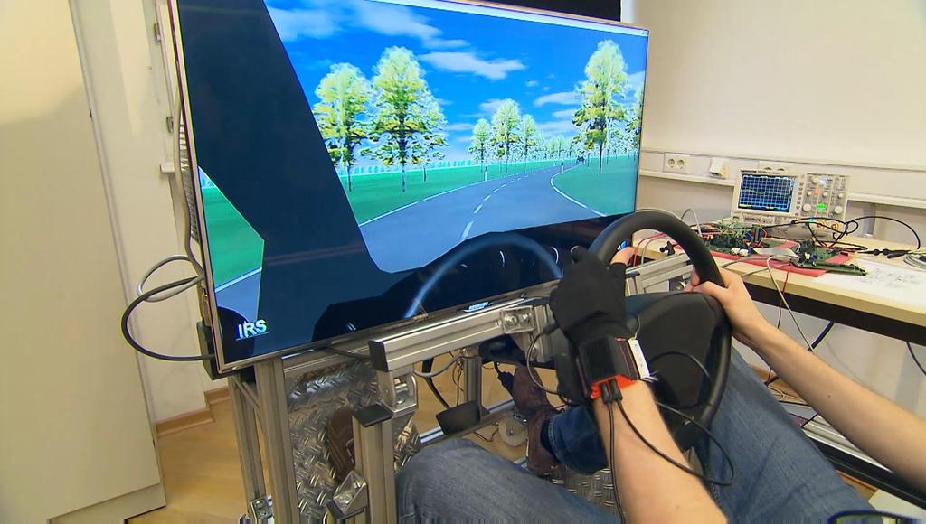
4 Cooperative ADAS Development Cooperative ADAS development requires test environment Virtual Car Simulation HW-in-the-loop Human 4 09/24/2014
5 Overview Driving Simulator Brake Simulator HiL Integration Overview Mechanics Overview Components Electronics Concepts Control Validation 5 09/24/2014


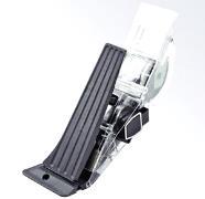
6 Advanced Driving Simulator Steering Wheel Realtime System Sound Throttle Screen Brake Sources: pk-soundandmusic.com/imagebase/ gif sensodrive.de/ we_thumbs /1035_5_s-pr-wheelHT-1.jpg autosieger.de/images/articles/continental_gaspedal_3.jpg bosch-automotivetechnology.com/media/en/ubk_europe/db_application/......downloads/pdf/antrieb/de_5/gs_datenbl_apm_de.pdf dspace.com/files/jpg2/px4_px10_px20-de-002_desktopversion_schraeg......_refl_dp_300dpi_200x250mm_cmyk_ jpg 6 09/24/2014
7 Overview Driving Simulator Brake Simulator HiL Integration Overview Mechanics Overview Components Electronics Concepts Control Validation 7 09/24/2014
8 Requirements Conventional Hybrid Human car perception characteristic pedal force characteristic Recuperation only Recuperation & Conventional Brake Nonlinear force characteristic Nonlinear dynamic Accuracy according perception Short response time 8 09/24/2014


9 New Concept Requirements Accuracy according perception Nonlinear force characteristic Short response time Nonlinear dynamic Basic concepts for pedal force simulator Passive Active New Concept: Brake Feedback Force Generation by Electric Drive 9 09/24/2014
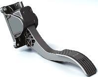
10 Brake Pedal Simulator - Mechanics Gearbox Connector Synchronous Motor Torque Sensor Pedal 10 09/24/2014

11 Brake Pedal Simulator - Mechanics Spring Limit Stops Incremental Encoder 11 09/24/2014
12 Electrical System Torque Sensor A/ D DSP CAN Interface Incremental Encoder QEI PWM CAN Bus Pedal Control Unit Gate SM Converter µc Unit QEI Drive Control Unit 12 09/24/2014
13 Software Architecture Sensor Input Filtering System State Estimation Reference Calculation Control Algorithm Emergency Stop Failure Detection System Supervision Output Enable & Limit Pedal Control Unit (DSP) Gate Signals Field-Oriented Control PWM Signal Drive Control Unit (μc) 13 09/24/2014
14 System Model Mechanics φ i Shaft Angle left/right side J M/G Inertia of Motor/Gearbox J 1 Inertia of connecting elements left J 2 Inertia right k DK Spring Constant of Torque Sensor & Connector Damping Rate d DK M M M F M P M G M Ri i Motor Torque Spring Torque Pedal Torque Pedal Mass Torque Friction Torque Gear Ratio 14 09/24/2014
15 System Equations Coupled nonlinear differential equations J ( t) k ( t) ( t) d ( t) ( t) i M ( t) M ( () t ) 1 1 DK 1 2 DK 1 2 M R1 1 J ( t) k ( t) ( t) d ( t) ( t) M ( t) M ( ( t) ) DK 1 2 DK 1 2 p R2 2 M G ( ( t) ) M ( ( t) ) 2 F 2 with J J i J J 2 1 1' ( M G) Constraints 0 ( t) : Angle of Limit Stops Nm i M ( t) 120 Nm M 15 09/24/2014
16 Software Architecture Sensor Input Filtering System State Estimation Reference Calculation Control Algorithm Emergency Stop Failure Detection System Supervision Output Enable & Limit Pedal Control Unit Gate Signals Field-Oriented Control PWM Signal Drive Control Unit 16 09/24/2014
17 PI-State Feedback Control V M S - ʃ K p K i - u z System M P x K x M P M S x u z Pedal torque Reference torque System states Command input torque to motor Disturbances 17 09/24/2014
18 System State Estimation Measurement equation ( t) () t 1 2 1() t 2( t) () t MMes( t) kdk 0 kdk 0 2() t Problem: Not all system states x and pedal torque M P can be measured Use of Extended Kalmanfilter for estimation Estimated quantities System states ˆ 1( t) ˆ 1( t) ˆ 2( t) ˆ 2( t) T Pedal torque ˆM P 18 09/24/2014
19 PI-State Feedback Control V K p z M S - ʃ K i - u System y K x ˆx ˆM P Kalmanfilter z k ˆM P M S ˆx z k Pedal torque, estimated Command input torque System states, estimated Disturbances, known, used in Kalmanfilter 19 09/24/2014
20 Measurement Results Deviations Root-Mean-Square-Error below human perception < 12N 20 09/24/2014
21 Summary Brake Pedal Simulator System Model Control Algorithm ( t) k 1 1( ) DK ddk d kdk d DK t d 1( t) J1 J1 J1 J 1 1( t)... dt 2( t) ( t) 2( t) k DK S F ( 2) 2 2( t) DK ddk k g k ddk d J2 J2 J2 J i 0 0 sign( 1) M R10 J1 J1 MM () t ( 2) sign MR 0 MP( t) Mg 0( 2) MF 0( 2) J2 J2 M S - ʃ V K p K i - x' Kalmanfilter M P ' K x z u System z k y System control and state estimation designed Simulator emulates arbitrary nonlinear force characteristics Required accuracy of pedal force achieved 21 09/24/2014
22 Overview Driving Simulator Brake Simulator HiL Integration Overview Mechanics Overview Components Electronics Concepts Control Validation 22 09/24/2014


23 Brake Pedal Simulator Integration CAN Brake Pedal Simulator CarMaker Source: duden.de/_media_/small/p/pc jpg dspace.com/files/jpg2/px4_px10_px20-de-002_desktopversion_schraeg......_refl_dp_300dpi_200x250mm_cmyk_ jpg 23 09/24/2014
24 Integration Concepts Concept 1 Brake pedal simulation in CarMaker Feedback force command to brake simulator Pedal position used in CarMaker Complex brake pedal simulation possible Concept 2 Brake pedal characteristic implemented on brake pedal simulator CarMaker selects characteristic Pedal position returned to CarMaker Higher torque / time resolution Brake Pedal Simulator CarMaker CAN 24 09/24/2014


25 Conclusion Advanced Driving Simulator presented Haptic interfaces available Test bench for cooperative ADAS 25 09/24/2014
26 Result 26 09/24/2014
27 Thank you for your attention 27 09/24/2014
28 Appendix 28 09/24/2014
29 Pedal Feedback Force Characteristic Real brake pedal force introduced by braking system Modelling with pedal force characteristic F ( ( )) Static s t F ( s( t), s( t)) F ( s( t)) Pedal Static F ( s( t), s( t)) Hysteresis F ( s( t), s( t)) Damping st ( ): Pedal Travel 29 09/24/2014
30 Pedal Feedback Force Characteristic F ( s( t)) F ( s( t), s( t)) d( s( t)) Static Hysteresis 30 09/24/2014
31 Pedal Feedback Force Characteristic Idealized pedal force characteristic for 2 different pedal velocities 31 09/24/2014
32 Software Architecture Emergency Stop Failure Detection System Supervision Drive Control Unit Sensor Input Filtering Output Enable & Limit PWM Signal CAN Signal Internal Signal System State Estimation Reference Calculation Pedal Control Unit Control Algorithm Field- Oriented Control Gate Signals 32 09/24/2014
33 System Equations Coupled differential equations J ( t) k ( t) ( t) d ( t) ( t) i M ( t) M ( () t ) 1 1 DK 1 2 DK 1 2 M R1 1 J ( t) k ( t) ( t) d ( t) ( t) M ( t) M ( () t ) DK 1 2 DK 1 2 p R2 2 M G ( ( t)) M ( ( t)) 2 F 2 Friction model M ( ) sign( ) M d Ri i i Ri 0 Ri i 33 09/24/2014
 ( t) d ( t) ( t) im ( t) M ( ) 1 1 DK 1 2 DK 1 2 M R1 1 J ( t) k ( t) ( t) d ( ) ( ) M ( t) M ( ) M ( ) M ( ) 2 2 DK 1 2 DK 1 2 p R2 2 G 2 F 2 S 2 2 2 34")
34 System Equations Coupled differnetial equations Non-Linearities l MG( 2) mp g sin 2( t) 2 Linearization through 0 and l sin MG( 2) mp g sin 2( t) 2 g g () t O t t J ( t) k ( t) ( t) d ( t) ( t) im ( t) M ( ) 1 1 DK 1 2 DK 1 2 M R1 1 J ( t) k ( t) ( t) d ( ) ( ) M ( t) M ( ) M ( ) M ( ) 2 2 DK 1 2 DK 1 2 p R2 2 G 2 F 2 S /24/2014
 ( ) ( ) F 2 2 2 Linearization through and cos sin MF ( 2) k a 2( t) M ( ) k ( ) ( t) F0 2 F 2 2 2 2 35")
35 System Equations Coupled differnetial equations J ( t) k ( t) ( t) d ( t) ( t) im ( t) M ( ) 1 1 DK 1 2 DK 1 2 M R1 1 J ( t) k ( t) ( t) d ( t) ( t) M ( t) M ( ) M ( ) M ( ) 2 2 DK 1 2 DK 1 2 p R2 2 G 2 F 2 Non-Linearities M k a sin t cos t ( ) ( ) ( ) F Linearization through and cos sin MF ( 2) k a 2( t) M ( ) k ( ) ( t) F0 2 F /24/2014
36 Control Concepts Overview State Feedback SISO - Control H - Control Control Compensator Constant State Feedback Deadbeat Controller PI State Feedback 36 09/24/2014
37 Control Implementation with additional Spring V K p z M S -M F - ʃ K i - u System y ˆx K x ˆM P -M F Kalmanfilter z k 37 09/24/2014
38 Identification 38 09/24/2014
39 State Space Model for Kalmanfilter System equation ˆ 1( t) k ˆ1( ) DK ddk d1 kdk d t DK 0 ˆ 1( t) J ˆ 1 J1 J1 J1 1( t) ˆ 2( t) ˆ 2( t)... ˆ ( 2( t) kdk ddk kdk gs kf 2) ddk d2 1 ˆ 2( t) Mˆ ( ) J2 J2 J2 J2 J 2 ˆ P t MP( t) /24/ J1 i MM( t) sign( 1) MR Mg 0 MF 0( 2) sign( 2) M R J2 0 0
40 State Space Model for Kalmanfilter Measurement equation ˆ 1() t ˆ 2( t) () t ( t) ˆ () t 2 2 MMes( t) k DK 0 kdk 0 0 ˆ 2() t ˆ MP () t 40 09/24/2014
41 Kalmanfilter - Simulation Time [s] 41 09/24/2014
42 Kalmanfilter - Simulation Time [s] 42 09/24/2014
43 Kalmanfilter - Measurement 43 09/24/2014


44 Measurement Setup Pedal force sensor attached to pedal Actuation via human foot Hence, no possibility to apply velocity profiles Record command input torque Used pedal characteristics: Quelle: m/medias/sys_mast er/ celum_assets/ _ _web_6407_png.jpg? /24/2014
ELEC4631 s Lecture 2: Dynamic Control Systems 7 March Overview of dynamic control systems
 ELEC4631 s Lecture 2: Dynamic Control Systems 7 March 2011 Overview of dynamic control systems Goals of Controller design Autonomous dynamic systems Linear Multi-input multi-output (MIMO) systems Bat flight
A Physically-Based Fault Detection and Isolation Method and Its Uses in Robot Manipulators
 des FA 4.13 Steuerung und Regelung von Robotern A Physically-Based Fault Detection and Isolation Method and Its Uses in Robot Manipulators Alessandro De Luca Dipartimento di Informatica e Sistemistica
Virtual Passive Controller for Robot Systems Using Joint Torque Sensors
 NASA Technical Memorandum 110316 Virtual Passive Controller for Robot Systems Using Joint Torque Sensors Hal A. Aldridge and Jer-Nan Juang Langley Research Center, Hampton, Virginia January 1997 National
University of Bristol - Explore Bristol Research. Publisher's PDF, also known as Version of record
 Watanabe, N., & Stoten, D. P. (214). Actuator control for a rapid prototyping railway bogie, using a dynamically substructured systems approach. In Proceedings of 12th International Conference on Motion
Overview of motors and motion control
 Overview of motors and motion control. Elements of a motion-control system Power upply High-level controller ow-level controller Driver Motor. Types of motors discussed here; Brushed, PM DC Motors Cheap,
Product description. Compact Modules. Characteristic features. Further highlights
 4 Compact Modules Product description Characteristic features Five fine-tuned sizes based on a compact precision aluminum profile with two integrated pre-tensioned ball rail systems Identical external
Lecture 12. Upcoming labs: Final Exam on 12/21/2015 (Monday)10:30-12:30
10:30-12:30") 289 Upcoming labs: Lecture 12 Lab 20: Internal model control (finish up) Lab 22: Force or Torque control experiments [Integrative] (2-3 sessions) Final Exam on 12/21/2015 (Monday)10:30-12:30 Today: Recap
289 Upcoming labs: Lecture 12 Lab 20: Internal model control (finish up) Lab 22: Force or Torque control experiments [Integrative] (2-3 sessions) Final Exam on 12/21/2015 (Monday)10:30-12:30 Today: Recap
Dynamic Characterization Results. Table of Contents. I. Introduction
 Dan Bolognini & Armen Mkhitarian ECE 492 Motor Controller + Modeling 5/9/16 Dynamic Characterization Results Table of Contents I. Introduction to Report II. Hypothesis III. Data Collection IV. Data Analysis
Introduction to Haptic Systems
 Introduction to Haptic Systems Félix Monasterio-Huelin & Álvaro Gutiérrez & Blanca Larraga October 8, 2018 Contents Contents 1 List of Figures 1 1 Introduction 2 2 DC Motor 3 3 1 DOF DC motor model with
Controlling the Apparent Inertia of Passive Human- Interactive Robots
 Controlling the Apparent Inertia of Passive Human- Interactive Robots Tom Worsnopp Michael Peshkin J. Edward Colgate Kevin Lynch Laboratory for Intelligent Mechanical Systems: Mechanical Engineering Department
HIL SIMULATION TECHNIQUE FOR NON-MODEL-BASED CONTROL OF DC SERVO-DRIVE WITH FRICTION. Teodor Dumitriu, Mihai Culea, Traian Munteanu, Emil Ceangă
 HIL IMULTION TECHNIQUE FOR NON-MODEL-BED CONTROL OF DC ERVO-DRIVE WITH FRICTION Teodor Dumitriu, Mihai Culea, Traian Munteanu, Emil Ceangă Dunărea de os University of Galaţi, Faculty of Electrical Engineering
Lab 3: Quanser Hardware and Proportional Control
 Lab 3: Quanser Hardware and Proportional Control The worst wheel of the cart makes the most noise. Benjamin Franklin 1 Objectives The goal of this lab is to: 1. familiarize you with Quanser s QuaRC tools
MEAM 510 Fall 2012 Bruce D. Kothmann
 Balancing g Robot Control MEAM 510 Fall 2012 Bruce D. Kothmann Agenda Bruce s Controls Resume Simple Mechanics (Statics & Dynamics) of the Balancing Robot Basic Ideas About Feedback & Stability Effects
Motion Control of Passive Haptic Device Using Wires with Servo Brakes
 The IEEE/RSJ International Conference on Intelligent Robots and Systems October 8-,, Taipei, Taiwan Motion Control of Passive Haptic Device Using Wires with Servo Brakes Yasuhisa Hirata, Keitaro Suzuki
DESIGN AND REALIZATION OF PROGRAMMABLE EMULATOR OF MECHANICAL LOADS. Milan Žalman, Radovan Macko
 DESIGN AND REALIZAION OF PROGRAMMABLE EMULAOR OF MECHANICAL LOADS Milan Žalman, Radovan Macko he Slovak University of echnology in Bratislava, Slovakia Abstract: his paper concerns design and realization
Aalborg Universitet. Disturbance Control of the Hydraulic Brake in a Wind Turbine Jepsen, Frank ; Søborg, Anders ; Yang, Zhenyu
 Aalborg Universitet Disturbance Control of the Hydraulic Brake in a Wind Turbine Jepsen, Frank ; Søborg, Anders ; Yang, Zhenyu Published in: Energy Conference and Exhibition (EnergyCon), 21 IEEE International
Satellite Attitude Control System Design Using Reaction Wheels Bhanu Gouda Brian Fast Dan Simon
 Satellite Attitude Control System Design Using Reaction Wheels Bhanu Gouda Brian Fast Dan Simon Outline 1. Overview of Attitude Determination and Control system. Problem formulation 3. Control schemes
Index. Index. More information. in this web service Cambridge University Press
 A-type elements, 4 7, 18, 31, 168, 198, 202, 219, 220, 222, 225 A-type variables. See Across variable ac current, 172, 251 ac induction motor, 251 Acceleration rotational, 30 translational, 16 Accumulator,
MEAM 510 Fall 2011 Bruce D. Kothmann
 Balancing g Robot Control MEAM 510 Fall 2011 Bruce D. Kothmann Agenda Bruce s Controls Resume Simple Mechanics (Statics & Dynamics) of the Balancing Robot Basic Ideas About Feedback & Stability Effects
VISUAL PHYSICS ONLINE DYNAMICS TYPES OF FORCES FRICTION
 VISUAL PHYSICS ONLINE DYNAMICS TYPES OF FORCES FRICTION Friction force: the force acting on the object which acts in a direction parallel to the surface. A simple model for friction F f is that it is proportional
Vehicle longitudinal speed control
 Vehicle longitudinal speed control Prof. R.G. Longoria Department of Mechanical Engineering The University of Texas at Austin February 10, 2015 1 Introduction 2 Control concepts Open vs. Closed Loop Control
AIRCRAFT BRAKING DYNAMICS AND BRAKE SYSTEM MODELING FOR FAULT DETECTION AND ISOLATION
 AIRCRAFT BRAKING DYNAMICS AND BRAKE SYSTEM MODELING FOR FAULT DETECTION AND ISOLATION Lucas Cardoso Navarro ITA São José dos Campos, São Paulo, Brazil Luiz Carlos Sandoval Goes ITA São José dos Campos,
Verification of an Automotive Headlight Leveling Circuit and Application Using Smart Component Property Extraction
 Verification of an Automotive Headlight Leveling Circuit and Application Using Smart Component Property Extraction Jérôme Kirscher,Michael Lenz, Dieter Metzner, Georg Pelz Infineon Technologies AG Automotive
THE REACTION WHEEL PENDULUM
 THE REACTION WHEEL PENDULUM By Ana Navarro Yu-Han Sun Final Report for ECE 486, Control Systems, Fall 2013 TA: Dan Soberal 16 December 2013 Thursday 3-6pm Contents 1. Introduction... 1 1.1 Sensors (Encoders)...
Quanser NI-ELVIS Trainer (QNET) Series: QNET Experiment #02: DC Motor Position Control. DC Motor Control Trainer (DCMCT) Student Manual
 Series: QNET Experiment #02: DC Motor Position Control. DC Motor Control Trainer (DCMCT) Student Manual") Quanser NI-ELVIS Trainer (QNET) Series: QNET Experiment #02: DC Motor Position Control DC Motor Control Trainer (DCMCT) Student Manual Table of Contents 1 Laboratory Objectives1 2 References1 3 DCMCT Plant
Quanser NI-ELVIS Trainer (QNET) Series: QNET Experiment #02: DC Motor Position Control DC Motor Control Trainer (DCMCT) Student Manual Table of Contents 1 Laboratory Objectives1 2 References1 3 DCMCT Plant
Video 5.1 Vijay Kumar and Ani Hsieh
 Video 5.1 Vijay Kumar and Ani Hsieh Robo3x-1.1 1 The Purpose of Control Input/Stimulus/ Disturbance System or Plant Output/ Response Understand the Black Box Evaluate the Performance Change the Behavior
Chapter 7 Control. Part Classical Control. Mobile Robotics - Prof Alonzo Kelly, CMU RI
 Chapter 7 Control 7.1 Classical Control Part 1 1 7.1 Classical Control Outline 7.1.1 Introduction 7.1.2 Virtual Spring Damper 7.1.3 Feedback Control 7.1.4 Model Referenced and Feedforward Control Summary
Speed Control of PMSM Drives by Using Neural Network Controller
 Advance in Electronic and Electric Engineering. ISSN 2231-1297, Volume 4, Number 4 (2014), pp. 353-360 Research India Publications http://www.ripublication.com/aeee.htm Speed Control of PMSM Drives by
Design, realization and modeling of a two-wheeled mobile pendulum system
 Design, realization and modeling of a two-wheeled mobile pendulum system ÁKOS ODRY 1, ISTVÁN HARMATI, ZOLTÁN KIRÁLY 1, PÉTER ODRY 1 1 Department of Control Engineering and Information Technology, College
Motion Control. Laboratory assignment. Case study. Lectures. compliance, backlash and nonlinear friction. control strategies to improve performance
 436-459 Advanced Control and Automation Motion Control Lectures traditional CNC control architecture modelling of components dynamic response of axes effects on contouring performance control strategies
Automatic Control Systems. -Lecture Note 15-
 -Lecture Note 15- Modeling of Physical Systems 5 1/52 AC Motors AC Motors Classification i) Induction Motor (Asynchronous Motor) ii) Synchronous Motor 2/52 Advantages of AC Motors i) Cost-effective ii)
BMS. comemso. Battery Cell Simulator. Battery Cell Simulation virtual Battery. BCS Generation 6. Battery. Battery Management System (BMS)
") BCS Generation 6 C Battery Simulation virtual Battery Battery Battery Management System () Copyright 2013. Alle Rechte vorbehalten. (BCS) Features supply range 0.01 8V up to 5A Accuracy +/-500µV 38HU System
BCS Generation 6 C Battery Simulation virtual Battery Battery Battery Management System () Copyright 2013. Alle Rechte vorbehalten. (BCS) Features supply range 0.01 8V up to 5A Accuracy +/-500µV 38HU System
DSCC PASSIVE CONTROL OF A HYDRAULIC HUMAN POWER AMPLIFIER USING A HYDRAULIC TRANSFORMER
 Proceedings of the ASME 25 Dynamic Systems and Control Conference DSCC25 October 28-3, 25, Columbus, Ohio, USA DSCC25-9734 PASSIVE CONTROL OF A HYDRAULIC HUMAN POWER AMPLIFIER USING A HYDRAULIC TRANSFORMER
557. Radial correction controllers of gyroscopic stabilizer
 557. Radial correction controllers of gyroscopic stabilizer M. Sivčák 1, J. Škoda, Technical University in Liberec, Studentská, Liberec, Czech Republic e-mail: 1 michal.sivcak@tul.cz; jan.skoda@pevnosti.cz
Modeling and control design for a semi-active suspension system with magnetorheological rotary brake
 Modeling and control design for a semi-active suspension system with magnetorheological rotary brake Geir-Arne Moslått, Erik Myklebust, Palmer Kolberg and Hamid Reza Karimi Department of Engineering, University
Mechatronics Engineering. Li Wen
 Mechatronics Engineering Li Wen Bio-inspired robot-dc motor drive Unstable system Mirko Kovac,EPFL Modeling and simulation of the control system Problems 1. Why we establish mathematical model of the control
Overview of the Seminar Topic
 Overview of the Seminar Topic Simo Särkkä Laboratory of Computational Engineering Helsinki University of Technology September 17, 2007 Contents 1 What is Control Theory? 2 History
dw dt T (w ( )) i =
) i =") Dan Bolognini & Armen Mkhitarian ECE 492 Motor Controller + Modeling Physics Model Memo 5/11/16 Abstract This memo provides information about the developed physics model for the fully integrated car using
Dan Bolognini & Armen Mkhitarian ECE 492 Motor Controller + Modeling Physics Model Memo 5/11/16 Abstract This memo provides information about the developed physics model for the fully integrated car using
«Energetic Macroscopic Representation for organization of HIL simulation»
 HIL 16 summer school Lille, 1-2 September 2016 http://l2ep.univ-lille1.fr/hil2016/ «Energetic Macroscopic Representation for organization of HIL simulation» Dr. Clément MAYET Prof. Alain BOUSCAYROL (L2EP,
Easily Adaptable Model of Test Benches for Internal Combustion Engines
 213 European Control Conference (ECC) July 17-19, 213, Zürich, Switzerland. Easily Adaptable Model of Test Benches for Internal Combustion Engines J. Blumenschein, P. Schrangl, T. E. Passenbrunner, H.
Implementation Issues for the Virtual Spring
 Implementation Issues for the Virtual Spring J. S. Freudenberg EECS 461 Embedded Control Systems 1 Introduction One of the tasks in Lab 4 is to attach the haptic wheel to a virtual reference position with
ROBUST FRICTION COMPENSATOR FOR HARMONIC DRIVE TRANSMISSION
 Proceedings of the 1998 IEEE International Conference on Control Applications Trieste, Italy 1-4 September 1998 TAO1 12:lO ROBUST FRICTION COMPENSATOR FOR HARMONIC DRIVE TRANSMISSION H.D. Taghirad K. N.
Chapter 2 SDOF Vibration Control 2.1 Transfer Function
 Chapter SDOF Vibration Control.1 Transfer Function mx ɺɺ( t) + cxɺ ( t) + kx( t) = F( t) Defines the transfer function as output over input X ( s) 1 = G( s) = (1.39) F( s) ms + cs + k s is a complex number:
Belt Tension Clamp. Drive Motor. Friction Brake. Load. Encoder 2. Drive. (4000 lines/rev incremental) Encoder 1. (4000 lines/rev incremental)
 Encoder 1. (4000 lines/rev incremental)") Industrial Servo System Introduction The first part this lab is to investigate how the dynamic response of a closed-loop system can be used to determine the mass moment of inertia of a model industrial
Industrial Servo System Introduction The first part this lab is to investigate how the dynamic response of a closed-loop system can be used to determine the mass moment of inertia of a model industrial
FAULT DETECTION for SPACECRAFT ATTITUDE CONTROL SYSTEM. M. Amin Vahid D. Mechanical Engineering Department Concordia University December 19 th, 2010
 FAULT DETECTION for SPACECRAFT ATTITUDE CONTROL SYSTEM M. Amin Vahid D. Mechanical Engineering Department Concordia University December 19 th, 2010 Attitude control : the exercise of control over the orientation
Modeling and Simulation of Cigarette Weight Control System
 Send Orders for Reprints to reprints@benthamscience.ae The Open Cybernetics & Systemics Journal,, 8, 67 6 Modeling and Simulation of Cigarette Weight Control System Open Access Yuan Zhanjun * Department
Linear Control Systems Solution to Assignment #1
 Linear Control Systems Solution to Assignment # Instructor: H. Karimi Issued: Mehr 0, 389 Due: Mehr 8, 389 Solution to Exercise. a) Using the superposition property of linear systems we can compute the
Joints Workshop Technical Talk
 Joints Workshop Technical Talk o.prof. Dr.-Ing.habil. Lothar Gaul Institut of Applied and Experimental Mechanics University of Stuttgart August 16, 2012 1 Important Topics in our Area Nonlinear or Linearized
Funnel control in mechatronics: An overview
 Funnel control in mechatronics: An overview Position funnel control of stiff industrial servo-systems C.M. Hackl 1, A.G. Hofmann 2 and R.M. Kennel 1 1 Institute for Electrical Drive Systems and Power Electronics
Balancing of an Inverted Pendulum with a SCARA Robot
 Balancing of an Inverted Pendulum with a SCARA Robot Bernhard Sprenger, Ladislav Kucera, and Safer Mourad Swiss Federal Institute of Technology Zurich (ETHZ Institute of Robotics 89 Zurich, Switzerland
Lecture 6: Control Problems and Solutions. CS 344R: Robotics Benjamin Kuipers
 Lecture 6: Control Problems and Solutions CS 344R: Robotics Benjamin Kuipers But First, Assignment 1: Followers A follower is a control law where the robot moves forward while keeping some error term small.
WHAT A SINGLE JOINT IS MADE OF RA
 Anthropomorphic robotics WHAT A SINGLE JOINT IS MADE OF Notation d F ( mv) mx Since links are physical objects with mass dt J J f i i J = moment of inertia F r F r Moment of inertia Around an axis m3 m1
Rigid Manipulator Control
 Rigid Manipulator Control The control problem consists in the design of control algorithms for the robot motors, such that the TCP motion follows a specified task in the cartesian space Two types of task
Design and Control of Compliant Humanoids. Alin Albu-Schäffer. DLR German Aerospace Center Institute of Robotics and Mechatronics
 Design and Control of Compliant Humanoids Alin Albu-Schäffer DLR German Aerospace Center Institute of Robotics and Mechatronics Torque Controlled Light-weight Robots Torque sensing in each joint Mature
Industrial Servo System
 Industrial Servo System Introduction The goal of this lab is to investigate how the dynamic response of a closed-loop system can be used to estimate the mass moment of inertia. The investigation will require
Mechatronic System Case Study: Rotary Inverted Pendulum Dynamic System Investigation
 Mechatronic System Case Study: Rotary Inverted Pendulum Dynamic System Investigation Dr. Kevin Craig Greenheck Chair in Engineering Design & Professor of Mechanical Engineering Marquette University K.
Experimental analysis and modeling of transmission torsional vibrations
 Experimental analysis and modeling of transmission torsional vibrations ENRICO GALVAGNO *, GUIDO RICARDO GUERCIONI, MAURO VELARDOCCHIA Department of Mechanical and Aerospace Engineering (DIMEAS) Politecnico
MODELLING ANALYSIS & DESIGN OF DSP BASED NOVEL SPEED SENSORLESS VECTOR CONTROLLER FOR INDUCTION MOTOR DRIVE
 International Journal of Advanced Research in Engineering and Technology (IJARET) Volume 6, Issue 3, March, 2015, pp. 70-81, Article ID: IJARET_06_03_008 Available online at http://www.iaeme.com/ijaret/issues.asp?jtypeijaret&vtype=6&itype=3
Robust Control of an Electronic Throttle System Via Switched Chattering Control: Benchmark Experiments
 Robust Control of an Electronic Throttle System Via Switched Chattering Control: Benchmark Experiments Yolanda Vidal*, Leonardo Acho*, and Francesc Pozo* * CoDAlab, Departament de Matemàtica Aplicada III,
Examples of Applications of Potential Functions in Problem Solving (Web Appendix to the Paper)
") Examples of Applications of otential Functions in roblem Solving (Web Appendix to the aper) Ali Mehrizi-Sani and Reza Iravani May 5, 2010 1 Introduction otential functions may be exploited to formulate
Examples of Applications of otential Functions in roblem Solving (Web Appendix to the aper) Ali Mehrizi-Sani and Reza Iravani May 5, 2010 1 Introduction otential functions may be exploited to formulate
Kinematics, Dynamics, and Vibrations FE Review Session. Dr. David Herrin March 27, 2012
 Kinematics, Dynamics, and Vibrations FE Review Session Dr. David Herrin March 7, 0 Example A 0 g ball is released vertically from a height of 0 m. The ball strikes a horizontal surface and bounces back.
Modeling of Dynamic Systems: Notes on Bond Graphs Version 1.0 Copyright Diane L. Peters, Ph.D., P.E.
 Modeling of Dynamic Systems: Notes on Bond Graphs Version 1.0 Copyright 2015 Diane L. Peters, Ph.D., P.E. Spring 2015 2 Contents 1 Overview of Dynamic Modeling 5 2 Bond Graph Basics 7 2.1 Causality.............................
q 1 F m d p q 2 Figure 1: An automated crane with the relevant kinematic and dynamic definitions.
 Robotics II March 7, 018 Exercise 1 An automated crane can be seen as a mechanical system with two degrees of freedom that moves along a horizontal rail subject to the actuation force F, and that transports
Trigonometric Saturated Controller for Robot Manipulators
 Trigonometric Saturated Controller for Robot Manipulators FERNANDO REYES, JORGE BARAHONA AND EDUARDO ESPINOSA Grupo de Robótica de la Facultad de Ciencias de la Electrónica Benemérita Universidad Autónoma
Application of Adaptive Thresholds in Robust Fault Detection of an Electro- Mechanical Single-Wheel Steering Actuator
 Preprints of the 8th IFAC Symposium on Fault Detection, Supervision and Safety of Technical Processes (SAFEPROCESS) August 29-31, 212. Mexico City, Mexico Application of Adaptive Thresholds in Robust Fault
FEEDBACK CONTROL SYSTEMS
 FEEDBAC CONTROL SYSTEMS. Control System Design. Open and Closed-Loop Control Systems 3. Why Closed-Loop Control? 4. Case Study --- Speed Control of a DC Motor 5. Steady-State Errors in Unity Feedback Control
LQ Control of a Two Wheeled Inverted Pendulum Process
 Uppsala University Information Technology Dept. of Systems and Control KN,HN,FS 2000-10 Last rev. September 12, 2017 by HR Reglerteknik II Instruction to the laboratory work LQ Control of a Two Wheeled
(Refer Slide Time: 00:01:30 min)
") Control Engineering Prof. M. Gopal Department of Electrical Engineering Indian Institute of Technology, Delhi Lecture - 3 Introduction to Control Problem (Contd.) Well friends, I have been giving you various
Control Engineering Prof. M. Gopal Department of Electrical Engineering Indian Institute of Technology, Delhi Lecture - 3 Introduction to Control Problem (Contd.) Well friends, I have been giving you various
Introduction to Control (034040) lecture no. 2
 lecture no. 2") Introduction to Control (034040) lecture no. 2 Leonid Mirkin Faculty of Mechanical Engineering Technion IIT Setup: Abstract control problem to begin with y P(s) u where P is a plant u is a control signal
Introduction to Control (034040) lecture no. 2 Leonid Mirkin Faculty of Mechanical Engineering Technion IIT Setup: Abstract control problem to begin with y P(s) u where P is a plant u is a control signal
Parameter Prediction and Modelling Methods for Traction Motor of Hybrid Electric Vehicle
 Page 359 World Electric Vehicle Journal Vol. 3 - ISSN 232-6653 - 29 AVERE Parameter Prediction and Modelling Methods for Traction Motor of Hybrid Electric Vehicle Tao Sun, Soon-O Kwon, Geun-Ho Lee, Jung-Pyo
Control of Mobile Robots
 Control of Mobile Robots Regulation and trajectory tracking Prof. Luca Bascetta (luca.bascetta@polimi.it) Politecnico di Milano Dipartimento di Elettronica, Informazione e Bioingegneria Organization and
Q-Motion Precision Linear Stage
 Q-Motion Precision Linear Stage High Forces and Small Design Due to Piezo Motors Q-545 Only 45 mm in width Push/pull force 8 N Incremental sensors with position resolution XY combinations without adapter
UNIVERSITY OF WASHINGTON Department of Aeronautics and Astronautics
 UNIVERSITY OF WASHINGTON Department of Aeronautics and Astronautics Modeling and Control of a Flexishaft System March 19, 2003 Christopher Lum Travis Reisner Amanda Stephens Brian Hass AA/EE-448 Controls
Application Note #3413
 Application Note #3413 Manual Tuning Methods Tuning the controller seems to be a difficult task to some users; however, after getting familiar with the theories and tricks behind it, one might find the
Exponential Controller for Robot Manipulators
 Exponential Controller for Robot Manipulators Fernando Reyes Benemérita Universidad Autónoma de Puebla Grupo de Robótica de la Facultad de Ciencias de la Electrónica Apartado Postal 542, Puebla 7200, México
Speed Control of Torsional Drive Systems with Backlash
 Speed Control of Torsional Drive Systems with Backlash S.Thomsen, F.W. Fuchs Institute of Power Electronics and Electrical Drives Christian-Albrechts-University of Kiel, D-2443 Kiel, Germany Phone: +49
A Novel Method on Disturbance Analysis and Feed-forward Compensation in Permanent Magnet Linear Motor System
 A Novel Method on Disturbance Analysis and Feed-forward Compensation in Permanent Magnet Linear Motor System Jonghwa Kim, Kwanghyun Cho, Hojin Jung, and Seibum Choi Department of Mechanical Engineering
Mathematical Modeling and Dynamic Simulation of a Class of Drive Systems with Permanent Magnet Synchronous Motors
 Applied and Computational Mechanics 3 (2009) 331 338 Mathematical Modeling and Dynamic Simulation of a Class of Drive Systems with Permanent Magnet Synchronous Motors M. Mikhov a, a Faculty of Automatics,
Linear Systems Theory
 ME 3253 Linear Systems Theory Review Class Overview and Introduction 1. How to build dynamic system model for physical system? 2. How to analyze the dynamic system? -- Time domain -- Frequency domain (Laplace
Stable Limit Cycle Generation for Underactuated Mechanical Systems, Application: Inertia Wheel Inverted Pendulum
 Stable Limit Cycle Generation for Underactuated Mechanical Systems, Application: Inertia Wheel Inverted Pendulum Sébastien Andary Ahmed Chemori Sébastien Krut LIRMM, Univ. Montpellier - CNRS, 6, rue Ada
Stepping Motors. Chapter 11 L E L F L D
 Chapter 11 Stepping Motors In the synchronous motor, the combination of sinusoidally distributed windings and sinusoidally time varying current produces a smoothly rotating magnetic field. We can eliminate
Non-Linear Swing-Up and Stabilizing Control of an Inverted Pendulum System
 EUROCON 3 Ljubljana, Slovenia Non-Linear Swing-Up and Stabilizing Control of an Inverted Pendulum System Marvin Bugeja Faculty of Engineering University of Malta Msida (MSD6) Malta email: merv@ieee.org
Tutorial 1 - Drive fundamentals and DC motor characteristics
 University of New South Wales School of Electrical Engineering & elecommunications ELEC4613 ELECRIC DRIVE SYSEMS utorial 1 - Drive fundamentals and DC motor characteristics 1. In the hoist drive system
Lab 6a: Pole Placement for the Inverted Pendulum
 Lab 6a: Pole Placement for the Inverted Pendulum Idiot. Above her head was the only stable place in the cosmos, the only refuge from the damnation of the Panta Rei, and she guessed it was the Pendulum
Lecture «Robot Dynamics»: Dynamics 2
 Lecture «Robot Dynamics»: Dynamics 2 151-0851-00 V lecture: CAB G11 Tuesday 10:15 12:00, every week exercise: HG E1.2 Wednesday 8:15 10:00, according to schedule (about every 2nd week) office hour: LEE
MODELLING ANALYSIS & DESIGN OF DSP BASED NOVEL SPEED SENSORLESS VECTOR CONTROLLER FOR INDUCTION MOTOR DRIVE
 INTERNATIONAL JOURNAL OF ADVANCED RESEARCH IN ENGINEERING International Journal of Advanced Research in Engineering and Technology (IJARET), ISSN 0976 6480(Print), ISSN 0976 6499(Online), AND TECHNOLOGY
EQUIVALENT SINGLE-DEGREE-OF-FREEDOM SYSTEM AND FREE VIBRATION
 1 EQUIVALENT SINGLE-DEGREE-OF-FREEDOM SYSTEM AND FREE VIBRATION The course on Mechanical Vibration is an important part of the Mechanical Engineering undergraduate curriculum. It is necessary for the development
Robot Manipulator Control. Hesheng Wang Dept. of Automation
 Robot Manipulator Control Hesheng Wang Dept. of Automation Introduction Industrial robots work based on the teaching/playback scheme Operators teach the task procedure to a robot he robot plays back eecute
Chapter 3. State Feedback - Pole Placement. Motivation
 Chapter 3 State Feedback - Pole Placement Motivation Whereas classical control theory is based on output feedback, this course mainly deals with control system design by state feedback. This model-based
Simple Car Dynamics. Outline. Claude Lacoursière HPC2N/VRlab, Umeå Universitet, Sweden, May 18, 2005
 Simple Car Dynamics Claude Lacoursière HPC2N/VRlab, Umeå Universitet, Sweden, and CMLabs Simulations, Montréal, Canada May 18, 2005 Typeset by FoilTEX May 16th 2005 Outline basics of vehicle dynamics different
Laboratory 11 Control Systems Laboratory ECE3557. State Feedback Controller for Position Control of a Flexible Joint
 Laboratory 11 State Feedback Controller for Position Control of a Flexible Joint 11.1 Objective The objective of this laboratory is to design a full state feedback controller for endpoint position control
MECH 3140 Final Project
 MECH 3140 Final Project Final presentation will be held December 7-8. The presentation will be the only deliverable for the final project and should be approximately 20-25 minutes with an additional 10
18.12 FORCED-DAMPED VIBRATIONS
 8. ORCED-DAMPED VIBRATIONS Vibrations A mass m is attached to a helical spring and is suspended from a fixed support as before. Damping is also provided in the system ith a dashpot (ig. 8.). Before the
Robust Control of Cooperative Underactuated Manipulators
 Robust Control of Cooperative Underactuated Manipulators Marcel Bergerman * Yangsheng Xu +,** Yun-Hui Liu ** * Automation Institute Informatics Technology Center Campinas SP Brazil + The Robotics Institute
Manufacturing Equipment Control
 QUESTION 1 An electric drive spindle has the following parameters: J m = 2 1 3 kg m 2, R a = 8 Ω, K t =.5 N m/a, K v =.5 V/(rad/s), K a = 2, J s = 4 1 2 kg m 2, and K s =.3. Ignore electrical dynamics
National Quali cations 2018
 H FOR X723/76/01 OFFICIAL USE National Quali cations 2018 Mark Engineering Science THURSDAY, 24 MAY 1:00 PM 3:00 PM *X7237601* Fill in these boxes and read what is printed below. Full name of centre Town
Product Description. Further highlights. Outstanding features. 4 Bosch Rexroth Corporation Miniature Linear Modules R310A 2418 (2009.
 4 Bosch Rexroth orporation Miniature Linear Modules R310A 2418 (2009.05) Product Description Outstanding features Rexroth Miniature Linear Modules are precise, ready-to-install linear motion systems that
2002 Prentice Hall, Inc. Gene F. Franklin, J. David Powell, Abbas Emami-Naeini Feedback Control of Dynamic Systems, 4e
 u Figure 2.1 Cruise-control model x Friction force bx m x u Figure 2.2 Free-body diagram for cruise control S P 278 Figure 2.3 Automobile suspension y m 2 k s b v car x m 1 k w Road surface r Inertial
ECEN 420 LINEAR CONTROL SYSTEMS. Lecture 6 Mathematical Representation of Physical Systems II 1/67
 1/67 ECEN 420 LINEAR CONTROL SYSTEMS Lecture 6 Mathematical Representation of Physical Systems II State Variable Models for Dynamic Systems u 1 u 2 u ṙ. Internal Variables x 1, x 2 x n y 1 y 2. y m Figure
Control. CSC752: Autonomous Robotic Systems. Ubbo Visser. March 9, Department of Computer Science University of Miami
 Control CSC752: Autonomous Robotic Systems Ubbo Visser Department of Computer Science University of Miami March 9, 2017 Outline 1 Control system 2 Controller Images from http://en.wikipedia.org/wiki/feed-forward