ECE251 VLSI System Design Spring Homework 1. Jinfeng Liu
|
|
|
- Poppy Chapman
- 5 years ago
- Views:
Transcription
1 ECE251 VLSI System Design Spring 2000 Homework 1 Jinfeng Liu /27/2000
![Problem 1: Procedure of solutions 1. Determine β n β n = An * C L / t df Ar = 1 2n (1 n) ln (2(1 n) V 0) 0) Vdd(1 n) V [ ] Given t df = 1.5ns, C L = 4pF, V dd = 3.3v, n = 0.1, V0 = 0.5 β n = 1.](/docs-images/90/103694176/images/2-1.jpg "057 e10-3 2. Determine W/L β n = µ ε/t ox * (W/L) In example of text book, (µ ε/t ox ) = 88.5 ua/v 2 for ntransistor (1u technology).")
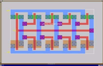
2 Problem 1: Procedure of solutions 1. Determine β n β n = An * C L / t df Ar = 1 2n (1 n) ln (2(1 n) V 0) 0) Vdd(1 n) V [ ] Given t df = 1.5ns, C L = 4pF, V dd = 3.3v, n = 0.1, V0 = 0.5 β n = e Determine W/L β n = µ ε/t ox * (W/L) In example of text book, (µ ε/t ox ) = 88.5 ua/v 2 for ntransistor (1u technology). Assume this value can approximately vary from ua/v 2, then the range of W/L is about To make sure the timing constraint is satisfied, larger (W/L) is chosen. 3. Layout design Since both transistors are quite large, I intend to make them in a relatively compact area. I have W/L = 44.5 for ntransistor and W/L=105.5 for ptransistor. Larger W/L will make shorter delay time, but power consumption is also going higher. Here are the screen shot and postscript file generated by Magic.
3 4. Simulation a. Irsim simulation The circuit is logically correct. (using HP35.PRM file). b. Spice simulation Load capacitor CL = 4PF is added between output and GND. The (W/L) value is extracted as W=89, L=2 for ntransistor and W=209, L=2 for ptransistor. Power consumption and switching transition analysis are made. * HSPICE file created from inv.ext - technology: scmos.lib '/users/kurdahi2/hspice/c10_rev6.1_hsp/hsp_dist/libs/hsp_nom_lib' N.LIB '/users/kurdahi2/hspice/c10_rev6.1_hsp/hsp_dist/libs/hsp_nom_lib' P.option scale=0.2u VCC Vdd GND DC 3.3 Vin in GND PULSE NS 0.1NS 0.1NS 6NS 12NS m0 out in Gnd Gnd n w=89 l=2 + ad=292 pd=102 as=458 ps=194 m1 out in Vdd Vdd p w=209 l=2 + ad=532 pd=222 as=848 ps=374 C0 out Gnd 4pf.TRAN 0.05NS 12NS.PRINT POWER.MEASURE TRAN avg_power AVG POWER from 0ns to 12ns.MEASURE TRAN max_power MAX POWER from 0ns to 12ns.MEASURE tdr TRIG V(in) VAL=1.65 FALL=1 TARG V(out) VAL=1.65 RISE=1.MEASURE tdf TRIG V(in) VAL=1.65 RISE=1 TARG V(out) VAL=1.65 FALL=1.MEASURE TRAN tr TRIG V(out) VAL=0.33 RISE=1 TARG V(out) VAL=2.97 RISE=1.MEASURE TRAN tf TRIG V(out) VAL=2.97 FALL=1 TARG V(out) VAL=0.33 FALL=1.OPTION POST = 2.END ** hspice subcircuit dictionary
4 i. Switching characteristics Spice output for delay: tdr= E-10 targ= E-09 trig= E-09 tdf= E-10 targ= E-09 trig= E-09 tr= E-09 targ= E-09 trig= E-09 tf= E-09 targ= E-09 trig= E-09 Tdrise = ns Tdfall = ns Delay time (Tdrise + Tdfall)/2 = ns Rise time = 1.57 ns Fall time = 1.36 ns The timing requirement is satisfied. ii. Power consumption
5 Spice output: avg_power= E-03 from= E+00 to= E-08 max_power= E-02 at= E-09 from= E+00 to= E-08 Average power = 3.79 mw Peak Power = 33.3 mw The power consumption is quite high because of low resistance. Problem 2 1. Layout design Use W=8, L=2 for ptransistror; W=4, L=2 for ntransistor. Five invertors are chained with the output of the last inverter looped back to input.
6
7 2. Spice simulation: a. Spice file is shown. Some capacitors are generated due to the wire capacitance. This will cause extra wire delay that will increase the period of oscillation. Analysis to power consumption is made. * HSPICE file created from osc.ext - technology: scmos.lib '/users/kurdahi2/hspice/c10_rev6.1_hsp/hsp_dist/libs/hsp_nom_lib' N.LIB '/users/kurdahi2/hspice/c10_rev6.1_hsp/hsp_dist/libs/hsp_nom_lib' P.option scale=0.2u VCC Vdd GND DC 3.3.IC V(out)=0 m0 a_2_n39 out Vdd Vdd p w=8 l=2 + ad=40 pd=26 as=200 ps=130 m1 a_18_n39 a_2_n39 Vdd Vdd p w=8 l=2 + ad=40 pd=26 as=0 ps=0 m2 a_34_n39 a_18_n39 Vdd Vdd p w=8 l=2 + ad=40 pd=26 as=0 ps=0 m3 a_50_n39 a_34_n39 Vdd Vdd p w=8 l=2 + ad=40 pd=26 as=0 ps=0 m4 out a_50_n39 Vdd Vdd p w=8 l=2 + ad=40 pd=26 as=0 ps=0 m5 a_2_n39 out Gnd Gnd n w=4 l=2 + ad=20 pd=18 as=100 ps=90 m6 a_18_n39 a_2_n39 Gnd Gnd n w=4 l=2 + ad=20 pd=18 as=0 ps=0 m7 a_34_n39 a_18_n39 Gnd Gnd n w=4 l=2 + ad=20 pd=18 as=0 ps=0 m8 a_50_n39 a_34_n39 Gnd Gnd n w=4 l=2 + ad=20 pd=18 as=0 ps=0 m9 out a_50_n39 Gnd Gnd n w=4 l=2 + ad=20 pd=18 as=0 ps=0 C0 Gnd GND 3.5fF C1 Vdd GND 3.5fF C2 a_50_n39 GND 2.3fF C3 a_34_n39 GND 2.3fF C4 a_18_n39 GND 2.3fF C5 a_2_n39 GND 2.3fF C6 out GND 3.3fF.TRAN 0.01NS 8NS.PRINT POWER.MEASURE TRAN avg_power AVG POWER from 0ns to 8ns.MEASURE TRAN max_power MAX POWER from 0ns to 8ns.OPTION POST = 2.END ** hspice subcircuit dictionary
 Power consumption Spice output: avg_power= 1.0258E-03 from= 0.")
8 b. Simulation results (1) Oscillation wave form Period = 0.7ns. I also made analysis to the single inverter. The delay time of single inverter is around 0.05ns, which is less than 1/10 of the oscillation period. This is because of the extra delay made by additional wire capacitance. (2) Power consumption Spice output: avg_power= E-03 from= E+00 to= E-09 max_power= E-03 at= E+00 from= E+00 to= E-09 Average Power = 1.02 mw Peak Power = 1.37 mw

9 Comments Problem 1: C L = 4pF is quite large. This will cause longer RC delays of the gate. To compensate this negative effect, R should be made as small as possible. Large channel width W will contribute to smaller R. The ptransistor has W=159 and the ntransistor has W=61. The problem is that the power consumption is likely to rise. This can be seen from the spice result. The solution requires very large transistors. To avoid extra capacitance, I ve tried many different ways to confine large transistors in small size. I was interested in the ring topology for both p-transistor and n-transistor, as shown in the layout. The irsim proves the correct logic, but spice fails since ext2spice translates the channel length L to 1, although it is 2 in layout. This layout is mis-extracted by Magic. Problem 2: The characteristics of the oscillator can be used to measure some attributes of the materials. The period of oscillation is a direct measure of one gate delay, which is determined by some parameters of the material. I tried to make the layout size as compact as possible. For ptransistor, W=8, L=2; for ntransistor, W=4, L=2. The compact layout can reduce the wire capacitance thus reduce the gate delay of each single inverter. Therefore, the period of oscillation has less interference with the wiring. However, since there is still wire capacitance the oscillation period is larger than 10 times to the delay of single inverter. Increasing the channel width W can further shorten the single inverter delay, thus contribute to shorter period time. But it will result in a larger layout size, which is likely to have more wire capacitance. On the other hand, decreasing the channel width W will yield more compact layout, which will reduce the wire delay. However, smaller W will cause larger resistance R of transistors. Since the delay time is in proportion to the product of RC, narrowing down the channel width may not shorten the delay time. Compared to the layout in problem 1, since the channel width is much smaller, the peak power consumption is far less than the condition in problem 1.
ECE251. VLSI System Design
 ECE251. VLSI System Design Project 4 SRAM Cell and Memory Array Operation Area Memory core 4661 mm 2 (256bit) Row Decoder 204.7 mm 2 Collumn Decoder Overall Design Predecoder 156.1 mm 2 Mux 629.2 mm 2
Topic 4. The CMOS Inverter
 Topic 4 The CMOS Inverter Peter Cheung Department of Electrical & Electronic Engineering Imperial College London URL: www.ee.ic.ac.uk/pcheung/ E-mail: p.cheung@ic.ac.uk Topic 4-1 Noise in Digital Integrated
Chapter 9. Estimating circuit speed. 9.1 Counting gate delays
 Chapter 9 Estimating circuit speed 9.1 Counting gate delays The simplest method for estimating the speed of a VLSI circuit is to count the number of VLSI logic gates that the input signals must propagate
UNIVERSITY OF CALIFORNIA, BERKELEY College of Engineering Department of Electrical Engineering and Computer Sciences
 UNIVERSITY OF CALIFORNIA, BERKELEY College of Engineering Department of Electrical Engineering and Computer Sciences Elad Alon Homework #7 Solutions EECS141 PROBLEM 1: Logical Effort with Velocity Saturated
UNIVERSITY OF CALIFORNIA, BERKELEY College of Engineering Department of Electrical Engineering and Computer Sciences
 UNIVERSITY OF CALIFORNIA, BERKELEY College of Engineering Department of Electrical Engineering and Computer Sciences Elad Alon Homework #2 - Solutions EECS141 Due Thursday, September 10, 5pm, box in 240
Lecture 7: SPICE Simulation
 Introduction to CMOS VLSI Design Lecture 7: SPICE Simulation David Harris Harvey Mudd College Spring 2004 Outline Introduction to SPICE DC Analysis Transient Analysis Subcircuits Optimization Power Measurement
Very Large Scale Integration (VLSI)
") Very Large Scale Integration (VLSI) Lecture 4 Dr. Ahmed H. Madian Ah_madian@hotmail.com Dr. Ahmed H. Madian-VLSI Contents Delay estimation Simple RC model Penfield-Rubenstein Model Logical effort Delay
Very Large Scale Integration (VLSI) Lecture 4 Dr. Ahmed H. Madian Ah_madian@hotmail.com Dr. Ahmed H. Madian-VLSI Contents Delay estimation Simple RC model Penfield-Rubenstein Model Logical effort Delay
UNIVERSITY OF CALIFORNIA, BERKELEY College of Engineering Department of Electrical Engineering and Computer Sciences
 UNIVERSITY OF LIFORNI, ERKELEY ollege of Engineering Department of Electrical Engineering and omputer Sciences Elad lon Homework #3 EE141 Due Thursday, September 13 th, 5pm, box outside 125 ory PROLEM
Integrated Circuits & Systems
 Federal University of Santa Catarina Center for Technology Computer Science & Electronics Engineering Integrated Circuits & Systems INE 5442 Lecture 13 The CMOS Inverter: dynamic behavior (delay) guntzel@inf.ufsc.br
THE INVERTER. Inverter
 THE INVERTER DIGITAL GATES Fundamental Parameters Functionality Reliability, Robustness Area Performance» Speed (delay)» Power Consumption» Energy Noise in Digital Integrated Circuits v(t) V DD i(t) (a)
EE115C Digital Electronic Circuits Homework #4
 EE115 Digital Electronic ircuits Homework #4 Problem 1 Power Dissipation Solution Vdd =1.0V onsider the source follower circuit used to drive a load L =20fF shown above. M1 and M2 are both NMOS transistors
CARNEGIE MELLON UNIVERSITY DEPARTMENT OF ELECTRICAL AND COMPUTER ENGINEERING DIGITAL INTEGRATED CIRCUITS FALL 2002
 CARNEGIE MELLON UNIVERSITY DEPARTMENT OF ELECTRICAL AND COMPUTER ENGINEERING 18-322 DIGITAL INTEGRATED CIRCUITS FALL 2002 Final Examination, Monday Dec. 16, 2002 NAME: SECTION: Time: 180 minutes Closed
Elad Alon Homework #2 EECS141 Due Thursday, September 9, 5pm, box in 240 Cory
 UNIVERSITY OF CALIFORNIA, BERKELEY College of Engineering Department of Electrical Engineering and Computer Sciences Elad Alon Homework #2 EECS141 Due Thursday, September 9, 5pm, box in 240 Cory PROBLEM
Digital Integrated Circuits
 Chapter 6 The CMOS Inverter 1 Contents Introduction (MOST models) 0, 1 st, 2 nd order The CMOS inverter : The static behavior: o DC transfer characteristics, o Short-circuit current The CMOS inverter :
CMPEN 411 VLSI Digital Circuits Spring 2012
 CMPEN 411 VLSI Digital Circuits Spring 2012 Lecture 09: Resistance & Inverter Dynamic View [Adapted from Rabaey s Digital Integrated Circuits, Second Edition, 2003 J. Rabaey, A. Chandrakasan, B. Nikolic]
Lecture 12 CMOS Delay & Transient Response
 EE 471: Transport Phenomena in Solid State Devices Spring 2018 Lecture 12 CMOS Delay & Transient Response Bryan Ackland Department of Electrical and Computer Engineering Stevens Institute of Technology
EEC 118 Lecture #5: CMOS Inverter AC Characteristics. Rajeevan Amirtharajah University of California, Davis Jeff Parkhurst Intel Corporation
 EEC 8 Lecture #5: CMOS Inverter AC Characteristics Rajeevan Amirtharajah University of California, Davis Jeff Parkhurst Intel Corporation Acknowledgments Slides due to Rajit Manohar from ECE 547 Advanced
ECE321 Electronics I
 ECE31 Electronics Lecture 1: CMOS nverter: Noise Margin & Delay Model Payman Zarkesh-Ha Office: ECE Bldg. 30B Office hours: Tuesday :00-3:00PM or by appointment E-mail: payman@ece.unm.edu Slide: 1 CMOS
The Physical Structure (NMOS)
") The Physical Structure (NMOS) Al SiO2 Field Oxide Gate oxide S n+ Polysilicon Gate Al SiO2 SiO2 D n+ L channel P Substrate Field Oxide contact Metal (S) n+ (G) L W n+ (D) Poly 1 Transistor Resistance Two
The Physical Structure (NMOS) Al SiO2 Field Oxide Gate oxide S n+ Polysilicon Gate Al SiO2 SiO2 D n+ L channel P Substrate Field Oxide contact Metal (S) n+ (G) L W n+ (D) Poly 1 Transistor Resistance Two
MOSFET and CMOS Gate. Copy Right by Wentai Liu
 MOSFET and CMOS Gate CMOS Inverter DC Analysis - Voltage Transfer Curve (VTC) Find (1) (2) (3) (4) (5) (6) V OH min, V V OL min, V V IH min, V V IL min, V OHmax OLmax IHmax ILmax NM L = V ILmax V OL max
ESE 570: Digital Integrated Circuits and VLSI Fundamentals
 ESE 570: Digital Integrated Circuits and VLSI Fundamentals Lec 15: March 15, 2018 Euler Paths, Energy Basics and Optimization Midterm! Midterm " Mean: 89.7 " Standard Dev: 8.12 2 Lecture Outline! Euler
Dynamic operation 20
 Dynamic operation 20 A simple model for the propagation delay Symmetric inverter (rise and fall delays are identical) otal capacitance is linear t p Minimum length devices R W C L t = 0.69R C = p W L 0.69
UNIVERSITY OF CALIFORNIA, BERKELEY College of Engineering Department of Electrical Engineering and Computer Sciences
 UNIVERSITY OF CALIFORNIA, BERKELEY College of Engineering Department of Electrical Engineering and Computer Sciences Elad Alon Homework #2 EECS141 Due Thursday, September 9, 5pm, box in 240 Cory PROBLEM
ESE 570: Digital Integrated Circuits and VLSI Fundamentals
 ESE 570: Digital Integrated Circuits and VLSI Fundamentals Lec 10: February 15, 2018 MOS Inverter: Dynamic Characteristics Penn ESE 570 Spring 2018 Khanna Lecture Outline! Inverter Power! Dynamic Characteristics
Lecture 4: DC & Transient Response
 Introduction to CMOS VLSI Design Lecture 4: DC & Transient Response David Harris Harvey Mudd College Spring 004 Outline DC Response Logic Levels and Noise Margins Transient Response Delay Estimation Slide
ECE 438: Digital Integrated Circuits Assignment #4 Solution The Inverter
 ECE 438: Digital Integrated Circuits Assignment #4 The Inverter Text: Chapter 5, Digital Integrated Circuits 2 nd Ed, Rabaey 1) Consider the CMOS inverter circuit in Figure P1 with the following parameters.
Interconnects. Wire Resistance Wire Capacitance Wire RC Delay Crosstalk Wire Engineering Repeaters. ECE 261 James Morizio 1
 Interconnects Wire Resistance Wire Capacitance Wire RC Delay Crosstalk Wire Engineering Repeaters ECE 261 James Morizio 1 Introduction Chips are mostly made of wires called interconnect In stick diagram,
Midterm. ESE 570: Digital Integrated Circuits and VLSI Fundamentals. Lecture Outline. Pass Transistor Logic. Restore Output.
 ESE 570: Digital Integrated Circuits and VLSI Fundamentals Lec 16: March 21, 2017 Transmission Gates, Euler Paths, Energy Basics Review Midterm! Midterm " Mean: 79.5 " Standard Dev: 14.5 2 Lecture Outline!
EE 466/586 VLSI Design. Partha Pande School of EECS Washington State University
 EE 466/586 VLSI Design Partha Pande School of EECS Washington State University pande@eecs.wsu.edu Lecture 8 Power Dissipation in CMOS Gates Power in CMOS gates Dynamic Power Capacitance switching Crowbar
Circuit A. Circuit B
 UNIVERSITY OF CALIFORNIA College of Engineering Department of Electrical Engineering and Computer Sciences Last modified on November 19, 2006 by Karl Skucha (kskucha@eecs) Borivoje Nikolić Homework #9
Next, we check the race condition to see if the circuit will work properly. Note that the minimum logic delay is a single sum.
 UNIVERSITY OF CALIFORNIA College of Engineering Department of Electrical Engineering and Computer Sciences Last modified on May 1, 2003 by Dejan Markovic (dejan@eecs.berkeley.edu) Prof. Jan Rabaey EECS
UNIVERSITY OF CALIFORNIA, BERKELEY College of Engineering Department of Electrical Engineering and Computer Sciences
 UNIVERSITY OF CALIFORNIA, BERKELEY College of Engeerg Department of Electrical Engeerg and Computer Sciences Elad Alon Homework # Solutions EECS141 PROBLEM 1: VTC In this problem we will analyze the noise
EEE 421 VLSI Circuits
 EEE 421 CMOS Properties Full rail-to-rail swing high noise margins» Logic levels not dependent upon the relative device sizes transistors can be minimum size ratioless Always a path to V dd or GND in steady
Announcements. EE141- Spring 2003 Lecture 8. Power Inverter Chain
 - Spring 2003 Lecture 8 Power Inverter Chain Announcements Homework 3 due today. Homework 4 will be posted later today. Special office hours from :30-3pm at BWRC (in lieu of Tuesday) Today s lecture Power
Analog Simulation. Digital simulation. Analog simulation. discrete values. discrete timing. continuous values. continuous timing
 Analog Simulation Digital simulation discrete values bit, boolean, enumerated, integer exception - floating point discrete timing cycle based - uniform time intervals event based - nonuniform time intervals
ESE 570: Digital Integrated Circuits and VLSI Fundamentals
 ESE 570: Digital Integrated Circuits and VLSI Fundamentals Lec 15: March 3, 2016 Combination Logic: Ratioed & Pass Logic, and Performance Lecture Outline! CMOS NOR2 Worst Case Analysis! Pass Transistor
DC and Transient. Courtesy of Dr. Daehyun Dr. Dr. Shmuel and Dr.
 DC and Transient Courtesy of Dr. Daehyun Lim@WSU, Dr. Harris@HMC, Dr. Shmuel Wimer@BIU and Dr. Choi@PSU http://csce.uark.edu +1 (479) 575-604 yrpeng@uark.edu Pass Transistors We have assumed source is
Lecture 5: DC & Transient Response
 Lecture 5: DC & Transient Response Outline q Pass Transistors q DC Response q Logic Levels and Noise Margins q Transient Response q RC Delay Models q Delay Estimation 2 Activity 1) If the width of a transistor
Lecture 6: DC & Transient Response
 Lecture 6: DC & Transient Response Slides courtesy of Deming Chen Slides based on the initial set from David Harris CMOS VLSI Design Outline Pass Transistors DC Response Logic Levels and Noise Margins
Homework Assignment #5 EE 477 Spring 2017 Professor Parker
 Homework Assignment #5 EE 477 Spring 2017 Professor Parker Question 1: (15%) Compute the worst-case rising and falling RC time constants at point B of the circuit below using the Elmore delay method. Assume
UNIVERSITY OF CALIFORNIA, BERKELEY College of Engineering Department of Electrical Engineering and Computer Sciences
 UNIVERSITY OF CAIFORNIA, BERKEEY College of Engineering Department of Electrical Engineering and Computer Sciences Elad Alon Homework #7 - Solutions EECS141 Due Thursday, October 22, 5pm, box in 240 Cory
EE115C Digital Electronic Circuits Homework #6
 Problem 1 Sizing of adder blocks Electrical Engineering Department Spring 2010 EE115C Digital Electronic Circuits Homework #6 Solution Figure 1: Mirror adder. Study the mirror adder cell (textbook, pages
E40M Capacitors. M. Horowitz, J. Plummer, R. Howe
 E40M Capacitors 1 Reading Reader: Chapter 6 Capacitance A & L: 9.1.1, 9.2.1 2 Why Are Capacitors Useful/Important? How do we design circuits that respond to certain frequencies? What determines how fast
CPE/EE 427, CPE 527 VLSI Design I Delay Estimation. Department of Electrical and Computer Engineering University of Alabama in Huntsville
 CPE/EE 47, CPE 57 VLSI Design I Delay Estimation Department of Electrical and Computer Engineering University of labama in Huntsville leksandar Milenkovic ( www.ece.uah.edu/~milenka ) Review: CMOS Circuit
Pluging in values for the parameters from table 6.1 we obtain switching resistance,
 Problem 10.1 By Vehid Suljic Using the parameters in Table 6.1 compare the hand-calculated effective digital switching resistance using Eq. (10.6) to the empirically derived values given in table 10.1.
Lecture 7 Circuit Delay, Area and Power
 Lecture 7 Circuit Delay, Area and Power lecture notes from S. Mitra Intro VLSI System course (EE271) Introduction to VLSI Systems 1 Circuits and Delay Introduction to VLSI Systems 2 Power, Delay and Area:
Integrated Circuits & Systems
 Federal University of Santa Catarina Center for Technology Computer Science & Electronics Engineering Integrated Circuits & Systems INE 5442 Lecture 14 The CMOS Inverter: dynamic behavior (sizing, inverter
Spiral 2 7. Capacitance, Delay and Sizing. Mark Redekopp
 2-7.1 Spiral 2 7 Capacitance, Delay and Sizing Mark Redekopp 2-7.2 Learning Outcomes I understand the sources of capacitance in CMOS circuits I understand how delay scales with resistance, capacitance
EE5780 Advanced VLSI CAD
 EE5780 Advanced VLSI CAD Lecture 4 DC and Transient Responses, Circuit Delays Zhuo Feng 4.1 Outline Pass Transistors DC Response Logic Levels and Noise Margins Transient Response RC Delay Models Delay
Practice 7: CMOS Capacitance
 Practice 7: CMOS Capacitance Digital Electronic Circuits Semester A 2012 MOSFET Capacitances MOSFET Capacitance Components 3 Gate to Channel Capacitance In general, the gate capacitance is similar to a
VLSI GATE LEVEL DESIGN UNIT - III P.VIDYA SAGAR ( ASSOCIATE PROFESSOR) Department of Electronics and Communication Engineering, VBIT
 Department of Electronics and Communication Engineering, VBIT") VLSI UNIT - III GATE LEVEL DESIGN P.VIDYA SAGAR ( ASSOCIATE PROFESSOR) contents GATE LEVEL DESIGN : Logic Gates and Other complex gates, Switch logic, Alternate gate circuits, Time Delays, Driving large
VLSI UNIT - III GATE LEVEL DESIGN P.VIDYA SAGAR ( ASSOCIATE PROFESSOR) contents GATE LEVEL DESIGN : Logic Gates and Other complex gates, Switch logic, Alternate gate circuits, Time Delays, Driving large
ENEE 359a Digital VLSI Design
 SLIDE 1 ENEE 359a Digital VLSI Design & Logical Effort Prof. blj@ece.umd.edu Credit where credit is due: Slides contain original artwork ( Jacob 2004) as well as material taken liberally from Irwin & Vijay
Lecture 5: DC & Transient Response
 Lecture 5: DC & Transient Response Outline Pass Transistors DC Response Logic Levels and Noise Margins Transient Response RC Delay Models Delay Estimation 2 Pass Transistors We have assumed source is grounded
ESE 570: Digital Integrated Circuits and VLSI Fundamentals
 ESE 570: Digital Integrated Circuits and VLSI Fundamentals Lec 24: April 19, 2018 Crosstalk and Wiring, Transmission Lines Lecture Outline! Crosstalk! Repeaters in Wiring! Transmission Lines " Where transmission
Fig. 1 CMOS Transistor Circuits (a) Inverter Out = NOT In, (b) NOR-gate C = NOT (A or B)
 Inverter Out = NOT In, (b) NOR-gate C = NOT (A or B)") 1 Introduction to Transistor-Level Logic Circuits 1 By Prawat Nagvajara At the transistor level of logic circuits, transistors operate as switches with the logic variables controlling the open or closed
1 Introduction to Transistor-Level Logic Circuits 1 By Prawat Nagvajara At the transistor level of logic circuits, transistors operate as switches with the logic variables controlling the open or closed
PURPOSE: See suggested breadboard configuration on following page!
 ECE4902 Lab 1 C2011 PURPOSE: Determining Capacitance with Risetime Measurement Reverse Biased Diode Junction Capacitance MOSFET Gate Capacitance Simulation: SPICE Parameter Extraction, Transient Analysis
EE 434 Lecture 33. Logic Design
 EE 434 Lecture 33 Logic Design Review from last time: Ask the inverter how it will interpret logic levels V IN V OUT V H =? V L =? V LARGE V H V L V H Review from last time: The two-inverter loop X Y X
! Crosstalk. ! Repeaters in Wiring. ! Transmission Lines. " Where transmission lines arise? " Lossless Transmission Line.
 ESE 570: Digital Integrated Circuits and VLSI Fundamentals Lec 24: April 19, 2018 Crosstalk and Wiring, Transmission Lines Lecture Outline! Crosstalk! Repeaters in Wiring! Transmission Lines " Where transmission
EECS 141: FALL 05 MIDTERM 1
 University of California College of Engineering Department of Electrical Engineering and Computer Sciences D. Markovic TuTh 11-1:3 Thursday, October 6, 6:3-8:pm EECS 141: FALL 5 MIDTERM 1 NAME Last SOLUTION
9/18/2008 GMU, ECE 680 Physical VLSI Design
 ECE680: Physical VLSI Design Chapter III CMOS Device, Inverter, Combinational circuit Logic and Layout Part 3 Combinational Logic Gates (textbook chapter 6) 9/18/2008 GMU, ECE 680 Physical VLSI Design
Homework Assignment #3 EE 477 Spring 2017 Professor Parker , -.. = 1.8 -, 345 = 0 -
 Homework Assignment #3 EE 477 Spring 2017 Professor Parker Note:! " = $ " % &' ( ) * ),! + = $ + % &' (, *,, -.. = 1.8 -, 345 = 0 - Question 1: a) (8%) Define the terms V OHmin, V IHmin, V ILmax and V
Name: Grade: Q1 Q2 Q3 Q4 Q5 Total. ESE370 Fall 2015
 University of Pennsylvania Department of Electrical and System Engineering Circuit-Level Modeling, Design, and Optimization for Digital Systems ESE370, Fall 205 Midterm Wednesday, November 4 Point values
EE115C Digital Electronic Circuits Homework #5
 EE115C Digital Electronic Circuits Homework #5 Due Thursday, May 13, 6pm @ 56-147E EIV Problem 1 Elmore Delay Analysis Calculate the Elmore delay from node A to node B using the values for the resistors
have followed. Submit the necessary plots showing the trade-off between propagation delays and transistor widths.
 H o m e w o r k 3 S o l u t i o n E C E 5 5 9 : M O S V L S I D e s i g n ( F a l l 0 0 9 ) E C E D e p a r t m e n t, P u r d u e U n i v e r s i t y Assigned: 06-Oct-009 Due: 15-Oct-009 I m p o r t a
EE141Microelettronica. CMOS Logic
 Microelettronica CMOS Logic CMOS logic Power consumption in CMOS logic gates Where Does Power Go in CMOS? Dynamic Power Consumption Charging and Discharging Capacitors Short Circuit Currents Short Circuit
ESE 570: Digital Integrated Circuits and VLSI Fundamentals
 ESE 570: Digital Integrated Circuits and VLSI Fundamentals Lec 23: April 17, 2018 I/O Circuits, Inductive Noise, CLK Generation Lecture Outline! Packaging! Variation and Testing! I/O Circuits! Inductive
Power Consumption in CMOS CONCORDIA VLSI DESIGN LAB
 Power Consumption in CMOS 1 Power Dissipation in CMOS Two Components contribute to the power dissipation:» Static Power Dissipation Leakage current Sub-threshold current» Dynamic Power Dissipation Short
Interconnects. Introduction
 Interconnects Wire Resistance Wire Capacitance Wire RC Delay Crosstalk Wire Engineering Repeaters ECE 261 Krish Chakrabarty 1 Introduction Chips are mostly made of ires called interconnect In stick diagram,
Announcements. EE141- Fall 2002 Lecture 7. MOS Capacitances Inverter Delay Power
 - Fall 2002 Lecture 7 MOS Capacitances Inverter Delay Power Announcements Wednesday 12-3pm lab cancelled Lab 4 this week Homework 2 due today at 5pm Homework 3 posted tonight Today s lecture MOS capacitances
Lecture 8-1. Low Power Design
 Lecture 8 Konstantinos Masselos Department of Electrical & Electronic Engineering Imperial College London URL: http://cas.ee.ic.ac.uk/~kostas E-mail: k.masselos@ic.ac.uk Lecture 8-1 Based on slides/material
EE213, Spr 2017 HW#3 Due: May 17 th, in class. Figure 1
 RULES: Please try to work on your own. Discussion is permissible, but identical submissions are unacceptable! Please show all intermediate steps: a correct solution without an explanation will get zero
P. R. Nelson 1 ECE418 - VLSI. Midterm Exam. Solutions
 P. R. Nelson 1 ECE418 - VLSI Midterm Exam Solutions 1. (8 points) Draw the cross-section view for A-A. The cross-section view is as shown below.. ( points) Can you tell which of the metal1 regions is the
Lecture Outline. ESE 570: Digital Integrated Circuits and VLSI Fundamentals. Total Power. Energy and Power Optimization. Worksheet Problem 1
 ESE 570: Digital Integrated Circuits and VLSI Fundamentals Lec 16: March 20, 2018 Energy and Power Optimization, Design Space Exploration Lecture Outline! Energy and Power Optimization " Tradeoffs! Design
Section 4. Nonlinear Circuits
 Section 4 Nonlinear Circuits 1 ) Voltage Comparators V P < V N : V o = V ol V P > V N : V o = V oh One bit A/D converter, Practical gain : 10 3 10 6 V OH and V OL should be far apart enough Response Time:
Lecture Outline. ESE 570: Digital Integrated Circuits and VLSI Fundamentals. Review: 1st Order RC Delay Models. Review: Two-Input NOR Gate (NOR2)
") ESE 570: Digital Integrated Circuits and VLSI Fundamentals Lec 14: March 1, 2016 Combination Logic: Ratioed and Pass Logic Lecture Outline! CMOS Gates Review " CMOS Worst Case Analysis! Ratioed Logic Gates!
ESE 570: Digital Integrated Circuits and VLSI Fundamentals Lec 14: March 1, 2016 Combination Logic: Ratioed and Pass Logic Lecture Outline! CMOS Gates Review " CMOS Worst Case Analysis! Ratioed Logic Gates!
ESE570 Spring University of Pennsylvania Department of Electrical and System Engineering Digital Integrated Cicruits AND VLSI Fundamentals
 University of Pennsylvania Department of Electrical and System Engineering Digital Integrated Cicruits AND VLSI Fundamentals ESE570, Spring 2018 Final Monday, Apr 0 5 Problems with point weightings shown.
Sample-and-Holds David Johns and Ken Martin University of Toronto
 Sample-and-Holds David Johns and Ken Martin (johns@eecg.toronto.edu) (martin@eecg.toronto.edu) slide 1 of 18 Sample-and-Hold Circuits Also called track-and-hold circuits Often needed in A/D converters
MOSFET: Introduction
 E&CE 437 Integrated VLSI Systems MOS Transistor 1 of 30 MOSFET: Introduction Metal oxide semiconductor field effect transistor (MOSFET) or MOS is widely used for implementing digital designs Its major
Objective and Outline. Acknowledgement. Objective: Power Components. Outline: 1) Acknowledgements. Section 4: Power Components
 Acknowledgements. Section 4: Power Components") Objective: Power Components Outline: 1) Acknowledgements 2) Objective and Outline 1 Acknowledgement This lecture note has been obtained from similar courses all over the world. I wish to thank all the
Objective: Power Components Outline: 1) Acknowledgements 2) Objective and Outline 1 Acknowledgement This lecture note has been obtained from similar courses all over the world. I wish to thank all the
ECE 342 Electronic Circuits. Lecture 35 CMOS Delay Model
 ECE 34 Electronic Circuits Lecture 35 CMOS Delay Model Jose E. Schutt-Aine Electrical & Computer Engineering University of Illinois jesa@illinois.edu ECE 34 Jose Schutt Aine 1 Digital Circuits V IH : Input
ESE570 Spring University of Pennsylvania Department of Electrical and System Engineering Digital Integrated Cicruits AND VLSI Fundamentals
 University of Pennsylvania Department of Electrical and System Engineering Digital Integrated Cicruits AND VLSI Fundamentals ESE570, Spring 017 Final Wednesday, May 3 4 Problems with point weightings shown.
L ECE 4211 UConn F. Jain Scaling Laws for NanoFETs Chapter 10 Logic Gate Scaling
 L13 04202017 ECE 4211 UConn F. Jain Scaling Laws for NanoFETs Chapter 10 Logic Gate Scaling Scaling laws: Generalized scaling (GS) p. 610 Design steps p.613 Nanotransistor issues (page 626) Degradation
Chapter 5. The Inverter. V1. April 10, 03 V1.1 April 25, 03 V2.1 Nov Inverter
 Chapter 5 The Inverter V1. April 10, 03 V1.1 April 25, 03 V2.1 Nov.12 03 Objective of This Chapter Use Inverter to know basic CMOS Circuits Operations Watch for performance Index such as Speed (Delay calculation)
EE 330 Lecture 37. Digital Circuits. Other Logic Families. Propagation Delay basic characterization Device Sizing (Inverter and multiple-input gates)
") EE 330 Lecture 37 Digital Circuits Other Logic Families Static Power Dissipation Propagation Delay basic characterization Device Sizing (Inverter and multiple-input gates) Review from Last Time Inverter
EE 330 Lecture 37 Digital Circuits Other Logic Families Static Power Dissipation Propagation Delay basic characterization Device Sizing (Inverter and multiple-input gates) Review from Last Time Inverter
EEC 118 Lecture #16: Manufacturability. Rajeevan Amirtharajah University of California, Davis
 EEC 118 Lecture #16: Manufacturability Rajeevan Amirtharajah University of California, Davis Outline Finish interconnect discussion Manufacturability: Rabaey G, H (Kang & Leblebici, 14) Amirtharajah, EEC
and V DS V GS V T (the saturation region) I DS = k 2 (V GS V T )2 (1+ V DS )
 I DS = k 2 (V GS V T )2 (1+ V DS )") ECE 4420 Spring 2005 Page 1 FINAL EXAMINATION NAME SCORE /100 Problem 1O 2 3 4 5 6 7 Sum Points INSTRUCTIONS: This exam is closed book. You are permitted four sheets of notes (three of which are your sheets
ECE 4420 Spring 2005 Page 1 FINAL EXAMINATION NAME SCORE /100 Problem 1O 2 3 4 5 6 7 Sum Points INSTRUCTIONS: This exam is closed book. You are permitted four sheets of notes (three of which are your sheets
Miscellaneous Lecture topics. Mary Jane Irwin [Adapted from Rabaey s Digital Integrated Circuits, 2002, J. Rabaey et al.]
![Miscellaneous Lecture topics. Mary Jane Irwin [Adapted from Rabaey s Digital Integrated Circuits, 2002, J. Rabaey et al.]](/thumbs/81/84503671.jpg "Miscellaneous Lecture topics. Mary Jane Irwin [Adapted from Rabaey s Digital Integrated Circuits, 2002, J. Rabaey et al.]") Miscellaneous Lecture topics Mary Jane Irwin [dapted from Rabaey s Digital Integrated Circuits, 2002, J. Rabaey et al.] MOS Switches MOS transistors can be viewed as simple switches. In an N-Switch, the
Miscellaneous Lecture topics Mary Jane Irwin [dapted from Rabaey s Digital Integrated Circuits, 2002, J. Rabaey et al.] MOS Switches MOS transistors can be viewed as simple switches. In an N-Switch, the
Interconnect (2) Buffering Techniques.Transmission Lines. Lecture Fall 2003
 Buffering Techniques.Transmission Lines. Lecture Fall 2003") Interconnect (2) Buffering Techniques.Transmission Lines Lecture 12 18-322 Fall 2003 A few announcements Partners Lab Due Times Midterm 1 is nearly here Date: 10/14/02, time: 3:00-4:20PM, place: in class
Interconnect (2) Buffering Techniques.Transmission Lines Lecture 12 18-322 Fall 2003 A few announcements Partners Lab Due Times Midterm 1 is nearly here Date: 10/14/02, time: 3:00-4:20PM, place: in class
COMP 103. Lecture 16. Dynamic Logic
 COMP 03 Lecture 6 Dynamic Logic Reading: 6.3, 6.4 [ll lecture notes are adapted from Mary Jane Irwin, Penn State, which were adapted from Rabaey s Digital Integrated Circuits, 2002, J. Rabaey et al.] COMP03
Delay Modelling Improvement for Low Voltage Applications
 Delay Modelling Improvement for Low Voltage Applications J.M. Daga, M. Robert and D. Auvergne Laboratoire d Informatique de Robotique et de Microélectronique de Montpellier LIRMM UMR CNRS 9928 Univ. Montpellier
EEC 118 Lecture #6: CMOS Logic. Rajeevan Amirtharajah University of California, Davis Jeff Parkhurst Intel Corporation
 EEC 118 Lecture #6: CMOS Logic Rajeevan mirtharajah University of California, Davis Jeff Parkhurst Intel Corporation nnouncements Quiz 1 today! Lab 2 reports due this week Lab 3 this week HW 3 due this
VLSI Design, Fall Logical Effort. Jacob Abraham
 6. Logical Effort 6. Logical Effort Jacob Abraham Department of Electrical and Computer Engineering The University of Texas at Austin VLSI Design Fall 207 September 20, 207 ECE Department, University of
Lecture 14 - Digital Circuits (III) CMOS. April 1, 2003
 CMOS. April 1, 2003") 6.12 - Microelectronic Devices and Circuits - Spring 23 Lecture 14-1 Lecture 14 - Digital Circuits (III) CMOS April 1, 23 Contents: 1. Complementary MOS (CMOS) inverter: introduction 2. CMOS inverter:
6.12 - Microelectronic Devices and Circuits - Spring 23 Lecture 14-1 Lecture 14 - Digital Circuits (III) CMOS April 1, 23 Contents: 1. Complementary MOS (CMOS) inverter: introduction 2. CMOS inverter:
CMOS logic gates. João Canas Ferreira. March University of Porto Faculty of Engineering
 CMOS logic gates João Canas Ferreira University of Porto Faculty of Engineering March 2016 Topics 1 General structure 2 General properties 3 Cell layout João Canas Ferreira (FEUP) CMOS logic gates March
Integrated Circuits & Systems
 Federal University of Santa Catarina Center for Technology Computer Science & Electronics Engineering Integrated Circuits & Systems INE 5442 Lecture 16 CMOS Combinational Circuits - 2 guntzel@inf.ufsc.br
ESE 570: Digital Integrated Circuits and VLSI Fundamentals
 ESE 570: Digital Integrated Circuits and VLSI Fundamentals Lec 17: March 23, 2017 Energy and Power Optimization, Design Space Exploration, Synchronous MOS Logic Lecture Outline! Energy and Power Optimization
3-Coefficient FIR Filter Chip. Nick Bodnaruk and Carrie Chung. April 11, 2001
 3-Coefficient FIR Filter Chip Nick Bodnaruk and Carrie Chung April 11, 2001 Table of Contents Functional Overview...3 Pinout Diagram... Chip Floorplan...5 Area and Design Time Data...7 Simulation Results...9
Advanced Current Mirrors and Opamps
 Advanced Current Mirrors and Opamps David Johns and Ken Martin (johns@eecg.toronto.edu) (martin@eecg.toronto.edu) slide 1 of 26 Wide-Swing Current Mirrors I bias I V I in out out = I in V W L bias ------------
EEC 116 Lecture #5: CMOS Logic. Rajeevan Amirtharajah Bevan Baas University of California, Davis Jeff Parkhurst Intel Corporation
 EEC 116 Lecture #5: CMOS Logic Rajeevan mirtharajah Bevan Baas University of California, Davis Jeff Parkhurst Intel Corporation nnouncements Quiz 1 today! Lab 2 reports due this week Lab 3 this week HW
ESE 570: Digital Integrated Circuits and VLSI Fundamentals
 ESE 570: Digital Integrated Circuits and VLSI Fundamentals Lec 19: March 29, 2018 Memory Overview, Memory Core Cells Today! Charge Leakage/Charge Sharing " Domino Logic Design Considerations! Logic Comparisons!