EE155/255 Green Electronics
|
|
|
- Cori Henry
- 5 years ago
- Views:
Transcription
1 EE155/255 Green Electronics Electric Motors 10/16/17 Prof. William Dally Computer Systems Laboratory Stanford University
2 Course Logistics Solar day is Monday 10/23 HW 3 is due today HW 4 out, due next Monday 10/23 Lab 3 must be checked off this week Lab 4 out this week
3 AH No Date Topic HW out HW in Lab out Lab ck Lab HW 1 9/25/17 Intro (basic converters) 1 1 Intro to ST32F3 Periodic Steady State 2 9/27/17 Embedded Prog/Power Elect. 3 10/2/17 Power Electronics - 1 (switches) AC Energy Meter Power Devices 4 10/4/17 Power Electronics - 2 (circuits) 5 10/9/17 Photovoltaics PV MPPT Motor control Matlab 6 10/11/17 Feedback Control 7 10/16/17 Electric Motors Motor control - Lab/ Feedback 8 10/18/17 Isolated Converters 9 10/23/17 Solar Day 5/PP PS Isolated Converters 10 10/25/17 Magnetics 11 10/30/17 Soft Switching 6 5/PP 6 5 Magnetics Magnetics and Inverters 12 11/1/17 Project Discussions 13 11/6/17 Inverters, Grid, PF, and Batteries 6 P 6 Project 14 11/8/17 Thermal & EMI 15 11/13/17 Quiz Review C /15/17 Grounding, and Debugging Q 11/15/17 Quiz - in the evening 11/20/17 Thanksgiving Break C2 11/22/17 Thanksgiving Break 17 11/27/17 Guest Lecture 18 11/29/17 Martin Fornage - Enphase C /4/17 Colin Campbell - Tesla 20 12/6/17 No Class TBD Project presentations P 12/15/17 Project webpage due
4 Course to Date We need sustainable energy systems Voltage converters PSSA, buck and boost Real circuits: losses, dead-time, snubbers PV cells characterized by a diode-like I-V curve PV systems 1f store energy, MPPT and invert Feedback control - PID Derivative looks ahead stabilizes Integral cancels residual error Actuators have limits EE155/255 Lecture 6 - Control
5 Agenda Motor Operation Motor Model Steady State and Transient Response Motor control with buck/boost Types of Motors Permanent magnet (PM) (brushed) Brushless permanent magnet (BLPM) AC Induction Radial vs axial flux Poles and phases
6 Motors and Generators are Everywhere Electric and Hybrid Cars Windmills and Hydro-Power Windows, door locks, Camera focus Printers Anywhere you need to convert between mechanical and electrical energy

7 Lorentz Force F = q(v x B)
8 In a Wire F = i(l x B)
9 Force is proportional to Current F = i(l x B)
10 Faraday Induction V = L (v x B)


11 Voltage is proportional to velocity V = L (v x B) This voltage pushes back on the current

12 Motors Just do this in a circle
13 Motor Equations V = L (v x B) V = K M w F = i(l x B) t = K M i t = I M (dw/dt) Simultaneously both a motor and a generator
14 Power is Conserved (mostly) P = VI P = (K M w)(t/k M ) P = wt
15 Models Develop mathematical expressions that predict behavior of physical (electrical and mechanical systems) Discard unnecessary detail to focus on the problem at hand
16 Motor Model L M R M + V B i M + - V =K =K i M -
17 Motor Model L M R M + V B i M + - V =K =K i M - Motor is characterized by four parameters Electrical: L M, R M Mechanical: I M Electro-mechanical: K M
18 Electrical: t E = L M /R M Two key time constants Mechanical: t M = R M I M /K M 2
19 Composite Model L M R M + i M + V M V =K M - 2 C M = I M /K M R F = 1/K F i L = L K M
20 Composite Model Angular Momentum Friction Energy output to shaft L M R M + i M + V M V =K M - 2 C M = I M /K M R F = 1/K F i L = L K M
21 Steady-State Response 0 Torque (Nm) max Anguar Velocity (rad/s) max
22 Steady-State Response t 0 = K M V B /R M 0 w max = V B /K M Torque (Nm) max t(w) = K M (V B -wk M )/R M Anguar Velocity (rad/s) max
23 Transient Response (rad/s) t (s)
24 Transient Response (rad/s) V B - L M i M R M C M = I M K K E R L = K F /K V =K Second order system 10 Time constant and damping factor depend on motor parameters t (s)
25 Composite Model Motor is second order, but typically electrical time constant L/R << mechanical time constant (I M K F /K E ), so we can approximate it as a first-order system. L M R M + i M + V M V =K M - 2 C M = I M /K M R F = 1/K F i L = L K M
26 Need to Control the Motor Applying full battery voltage to a motor system with significant inertia will generally result in destructive currents R M is small milliohms Locked rotor current I LR = V B /R M is large A Unless inertia is very low, sustained current will Destroy switching element (MOSFET or IGBT) Burn insulation off of windings Disconnect windings from brushes Fuse windings and wiring All of the above
27 Suppose I want to Apply 16V to the motor but all I have is a 48V battery?
28 Buck Converter Motor controller is just a buck converter Rotor winding is the inductor L Back-EMF sets the output voltage V E a V Batt + - L i L b + - V E
29 What PWM Frequency? Suppose L m = 1mH V = 48V What frequency is needed to keep ripple current < 1A?
30 Regenerative Braking
31 Boost Converter b V E + - L i L a + - V Batt
32 Brushed permanent magnet motors (PM) Types of Motors What we have been talking about so far PM on stator, windings on rotor switched by commutator Brushless permanent magnet motors (BLPM) Like PM but no brushes PM on rotor Use controller to commutate stator current AC voltage required on windings AC induction motors Rotor is shorted winding acts like a transformer Stator excites rotor and generates field Series and shunt wound DC motors Separate stator and rotor windings Radial and axial flux versions of all of the above
33 All Motors Look Like a Brushed PM Motor Inverter AC Induction Motor
34 All Motors Look Like a Brushed PM Motor Torque is proportional to current Velocity generates back EMF Inverter AC Induction Motor Only difference is need for inverter, electronic commutator or other power shaping electronics
35 Separate Motor Controller Design Brushed PM Controller + Inverter Combine redundant elements Inverter needs to estimate rotor position and/or velocity PM Controller Inverter AC Induction Motor Or Brushless PM
36 Brushless PM Motor 1 N 3 S 2
37 Consider Brushless PM as a Generator 1 Angle 0 is up (0,1) Phases at 0, 120, 240 degrees Field produced by rotor at angle q: B = (B 0 sinq, B 0 cosq) N f = BA = (B 0 Asinq, B 0 Acosq) 3 S 2 Voltage in phase i is df/dt at a i df(q)/dt = (B 0 Awcosq, -B 0 Awsinq) V(a) = df(q)/dtu(a) V(a) = -B 0 Awsin(q-a)
38 Back EMF 1 N V(a) = -Kwsin(q-a) Open-circuit voltage (back EMF) of each phase is a sinusoid that 3 S 2 Is proportional to w Reaches peak value when rotor is 90 degrees from phase.
39 Torque 1 N Current in winding i produces a field at angle a i Torque is effect of this field on the rotor at angle q t = -(Ki)sin(q-a i ) 3 S 2 Power is conserved tw = -w(ki)sin(q-a i ) = -(i)kwsin(q-a i ) = iv
40 Torque t = -(Ki)sin(q-a i ) 1 Torque is proportional to current N Torque is maximum when rotor is 90 degrees behind phase 3 S 2 Torque from each phase is sinusoidal
41 Rotating Stator Field 1 N Stator field is superposition of fields from each phase To generate a field at angle y apply current I i = cos(y-a i ) 3 S 2 To phase i Note currents sum to zero with evenly spaced phases
42 Sense rotor position Hall effect sensors Measure phase current and voltage Estimate position by fitting model Brushless PM Motors Stator creates rotating magnetic field Set angle at 90-degrees ahead of rotor to maximize torque May be effective 90 degrees in multi-pole arrangements Stator field rotates at same rate as rotor w s = w r Leads rotor by 90 degrees Q s = Q r + 90
43 Angle of Magnetic Fields Stator Field Rotor Field

44 Brushless PM Motors
45 Animations of BLPM

46 Example Stator from fan

47 Stator Outside
48 AC Induction Motor 3' 2 1 1' 2' 3 EE 155/255 Lecture 8 - Isolated Converters
49 Equivalent Circuit L S R S L R + i M R R V M L M 1-s s R R - Rotor voltage scaled by slip s = (w s -w r )/w s EE 155/255 Lecture 8 - Isolated Converters
50 Phase of Currents and Voltages V S I S V R I R I M EE 155/255 Lecture 8 - Isolated Converters
51 Torque Calculations Developed power L S R S L R P = (1-s/s)I 2 R r + i M R R Torque V M L M 1-s s R R t = P/w = (1-s/s)I 2 R r /w r - Starting Torque t 0 = I 2 R r /w s 1 3 2
52 Torque and Efficiency τ (Nm) ν ω s (rad/s) EE 155/255 Lecture 8 - Isolated Converters
53 Torque and Efficiency vs Slip s τ (Nm) ν σ
54 AC Motor Control Low Speed V max 8 V s (Volts) 6 4 I max 2 r s (rad/s)
55 AC Motor Control High Speed V max 8 V s (Volts) 6 4 I max 2 r s (rad/s) 5 6 7
56 AC Induction Animation
57 Inverters BLPM and Induction motors both need 3-phase inverters 3-channel PWM half-bridge Control to synthesize desired phase angle BLPM sense (and estimate) rotor position set field to equal this position AC sense rotor velocity generate rotating field with desired slip
58 3-F Inverter Power Path A B C 48V 34AH F 1 C 1 R CS A A B B C C
59 3-F Inverter Power Path Duty factor applied to phase i D i = D V x D i (q) Bipolar, D in [-1,1] -1 is 0%, 0 is 50%, 1 is 100% Level shift to make min 0% A B C 48V 34AH F 1 C 1 R CS A A B B C C

60 Axial Flux and Radial Flux Motor Geometry


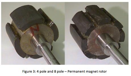
61 Poles and Phases A stator can be described as having P phases and N=kP poles. Rotating phases Q degrees rotates field Q/k degrees w s = kw m Number or rotor poles may differ to reduce camming
62

63
 BLPM requires rotating field 48V 34AH F1 C1 RCS A A A B C B C B C Torque")
64 Summary + V B L M R M i M + - V =K =K i M Motors and generators ubiquitous - Voltage is velocity, current is torque V = K M w, t = K M i = I M (dw/dt) Load curve and transient response Control motor with PWM + V B - L M i M R M C M = I M K K E R L = K F /K + V =K - Buck converter during drive 0 Boost during braking (gen) BLPM requires rotating field 48V 34AH F1 C1 RCS A A A B C B C B C Torque (Nm) max Determine rotor angle max Apply stator current for perpendicular fields Anguar Velocity (rad/s) In rotor reference field looks just like a brushed motor AC Induction motors Rotor Field Torque is function of slip Equivalent circuit s = ω s ω r ω s Stator Field Multiple poles + LS im RS LR RR w s = kw m - RR 1-s s VM LM
65 YAH No Date Topic HW out HW in Lab out Lab ck Lab HW 1 9/25/17 Intro (basic converters) 1 1 Intro to ST32F3 Periodic Steady State 2 9/27/17 Embedded Prog/Power Elect. 3 10/2/17 Power Electronics - 1 (switches) AC Energy Meter Power Devices 4 10/4/17 Power Electronics - 2 (circuits) 5 10/9/17 Photovoltaics PV MPPT Motor control Matlab 6 10/11/17 Feedback Control 7 10/16/17 Electric Motors Motor control - Lab/ Feedback 8 10/18/17 Isolated Converters 9 10/23/17 Solar Day 5/PP PS Isolated Converters 10 10/25/17 Magnetics 11 10/30/17 Soft Switching 6 5/PP 6 5 Magnetics Magnetics and Inverters 12 11/1/17 Project Discussions 13 11/6/17 Inverters, Grid, PF, and Batteries 6 P 6 Project 14 11/8/17 Thermal & EMI 15 11/13/17 Quiz Review C /15/17 Grounding, and Debugging Q 11/15/17 Quiz - in the evening 11/20/17 Thanksgiving Break C2 11/22/17 Thanksgiving Break 17 11/27/17 Guest Lecture 18 11/29/17 Martin Fornage - Enphase C /4/17 Colin Campbell - Tesla 20 12/6/17 No Class TBD Project presentations P 12/15/17 Project webpage due
EE155/255 Green Electronics
 EE155/255 Green Electronics Electric Motors 10/19/16 Prof. William Dally Computer Systems Laboratory Stanford University This week is flipped Course Logistics Discussion on 10/17, Motors on 10/19, Isolated
EE155/255 Green Electronics
 EE155/255 Green Electronics Power Circuits 10/4/17 Prof. William Dally Computer Systems Laboratory Stanford University HW2 due Monday 10/9 Lab groups have been formed Lab1 signed off this week Lab2 out
ENGG4420 LECTURE 7. CHAPTER 1 BY RADU MURESAN Page 1. September :29 PM
 CHAPTER 1 BY RADU MURESAN Page 1 ENGG4420 LECTURE 7 September 21 10 2:29 PM MODELS OF ELECTRIC CIRCUITS Electric circuits contain sources of electric voltage and current and other electronic elements such
Mathematical Modeling and Dynamic Simulation of a Class of Drive Systems with Permanent Magnet Synchronous Motors
 Applied and Computational Mechanics 3 (2009) 331 338 Mathematical Modeling and Dynamic Simulation of a Class of Drive Systems with Permanent Magnet Synchronous Motors M. Mikhov a, a Faculty of Automatics,
Texas A & M University Department of Mechanical Engineering MEEN 364 Dynamic Systems and Controls Dr. Alexander G. Parlos
 Texas A & M University Department of Mechanical Engineering MEEN 364 Dynamic Systems and Controls Dr. Alexander G. Parlos Lecture 6: Modeling of Electromechanical Systems Principles of Motor Operation
An Introduction to Electrical Machines. P. Di Barba, University of Pavia, Italy
 An Introduction to Electrical Machines P. Di Barba, University of Pavia, Italy Academic year 0-0 Contents Transformer. An overview of the device. Principle of operation of a single-phase transformer 3.
Revision Guide for Chapter 15
 Revision Guide for Chapter 15 Contents tudent s Checklist Revision otes Transformer... 4 Electromagnetic induction... 4 Generator... 5 Electric motor... 6 Magnetic field... 8 Magnetic flux... 9 Force on
EE 410/510: Electromechanical Systems Chapter 4
 EE 410/510: Electromechanical Systems Chapter 4 Chapter 4. Direct Current Electric Machines and Motion Devices Permanent Magnet DC Electric Machines Radial Topology Simulation and Experimental Studies
Control of Wind Turbine Generators. James Cale Guest Lecturer EE 566, Fall Semester 2014 Colorado State University
 Control of Wind Turbine Generators James Cale Guest Lecturer EE 566, Fall Semester 2014 Colorado State University Review from Day 1 Review Last time, we started with basic concepts from physics such as
INDUCTION MOTOR MODEL AND PARAMETERS
 APPENDIX C INDUCTION MOTOR MODEL AND PARAMETERS C.1 Dynamic Model of the Induction Motor in Stationary Reference Frame A three phase induction machine can be represented by an equivalent two phase machine
Definition Application of electrical machines Electromagnetism: review Analogies between electric and magnetic circuits Faraday s Law Electromagnetic
 Definition Application of electrical machines Electromagnetism: review Analogies between electric and magnetic circuits Faraday s Law Electromagnetic Force Motor action Generator action Types and parts
Mathematical Modelling of Permanent Magnet Synchronous Motor with Rotor Frame of Reference
 Mathematical Modelling of Permanent Magnet Synchronous Motor with Rotor Frame of Reference Mukesh C Chauhan 1, Hitesh R Khunt 2 1 P.G Student (Electrical),2 Electrical Department, AITS, rajkot 1 mcchauhan1@aits.edu.in
ELECTROMAGNETIC OSCILLATIONS AND ALTERNATING CURRENT
 Chapter 31: ELECTROMAGNETIC OSCILLATIONS AND ALTERNATING CURRENT 1 A charged capacitor and an inductor are connected in series At time t = 0 the current is zero, but the capacitor is charged If T is the
ELECTRICAL ENGINEERING
 ELECTRICAL ENGINEERING Subject Code: EE Course Structure Sections/Units Section A Unit 1 Unit 2 Unit 3 Unit 4 Unit 5 Unit 6 Unit 7 Section B Section C Section D Section E Section F Section G Section H
Revision Guide for Chapter 15
 Revision Guide for Chapter 15 Contents Revision Checklist Revision otes Transformer...4 Electromagnetic induction...4 Lenz's law...5 Generator...6 Electric motor...7 Magnetic field...9 Magnetic flux...
Step Motor Modeling. Step Motor Modeling K. Craig 1
 Step Motor Modeling Step Motor Modeling K. Craig 1 Stepper Motor Models Under steady operation at low speeds, we usually do not need to differentiate between VR motors and PM motors (a hybrid motor is
School of Mechanical Engineering Purdue University. ME375 ElectroMechanical - 1
 Electro-Mechanical Systems DC Motors Principles of Operation Modeling (Derivation of fg Governing Equations (EOM)) Block Diagram Representations Using Block Diagrams to Represent Equations in s - Domain
(a) Torsional spring-mass system. (b) Spring element.
 Torsional spring-mass system. (b) Spring element.") m v s T s v a (a) T a (b) T a FIGURE 2.1 (a) Torsional spring-mass system. (b) Spring element. by ky Wall friction, b Mass M k y M y r(t) Force r(t) (a) (b) FIGURE 2.2 (a) Spring-mass-damper system. (b)
m v s T s v a (a) T a (b) T a FIGURE 2.1 (a) Torsional spring-mass system. (b) Spring element. by ky Wall friction, b Mass M k y M y r(t) Force r(t) (a) (b) FIGURE 2.2 (a) Spring-mass-damper system. (b)
Equal Pitch and Unequal Pitch:
 Equal Pitch and Unequal Pitch: Equal-Pitch Multiple-Stack Stepper: For each rotor stack, there is a toothed stator segment around it, whose pitch angle is identical to that of the rotor (θs = θr). A stator
Massachusetts Institute of Technology Department of Electrical Engineering and Computer Science Electric Machines
 Massachusetts Institute of Technology Department of Electrical Engineering and Computer Science 6.685 Electric Machines Problem Set 10 Issued November 11, 2013 Due November 20, 2013 Problem 1: Permanent
a. Type 0 system. b. Type I system. c. Type 2 system. d. Type 3 system.
 1-The steady-state error of a feedback control system with an acceleration input becomes finite in a a. Type 0 system. b. Type I system. c. Type 2 system. d. Type 3 system. 2-A good control system has
JRE SCHOOL OF Engineering
 JRE SCHOOL OF Engineering Class Test-1 Examinations September 2014 Subject Name Electromechanical Energy Conversion-II Subject Code EEE -501 Roll No. of Student Max Marks 30 Marks Max Duration 1 hour Date
PESIT Bangalore South Campus Hosur road, 1km before Electronic City, Bengaluru -100 Department of Electronics & Communication Engineering
 QUESTION PAPER INTERNAL ASSESSMENT TEST 2 Date : /10/2016 Marks: 0 Subject & Code: BASIC ELECTRICAL ENGINEERING -15ELE15 Sec : F,G,H,I,J,K Name of faculty : Dhanashree Bhate, Hema B, Prashanth V Time :
3 d Calculate the product of the motor constant and the pole flux KΦ in this operating point. 2 e Calculate the torque.
 Exam Electrical Machines and Drives (ET4117) 11 November 011 from 14.00 to 17.00. This exam consists of 5 problems on 4 pages. Page 5 can be used to answer problem 4 question b. The number before a question
Automatic Control Systems. -Lecture Note 15-
 -Lecture Note 15- Modeling of Physical Systems 5 1/52 AC Motors AC Motors Classification i) Induction Motor (Asynchronous Motor) ii) Synchronous Motor 2/52 Advantages of AC Motors i) Cost-effective ii)
MODELING AND HIGH-PERFORMANCE CONTROL OF ELECTRIC MACHINES
 MODELING AND HIGH-PERFORMANCE CONTROL OF ELECTRIC MACHINES JOHN CHIASSON IEEE PRESS ü t SERIES ON POWER ENGINEERING IEEE Press Series on Power Engineering Mohamed E. El-Hawary, Series Editor The Institute
ECE 5670/6670 Lab 8. Torque Curves of Induction Motors. Objectives
 ECE 5670/6670 Lab 8 Torque Curves of Induction Motors Objectives The objective of the lab is to measure the torque curves of induction motors. Acceleration experiments are used to reconstruct approximately
EDEXCEL NATIONALS UNIT 5 - ELECTRICAL AND ELECTRONIC PRINCIPLES. ASSIGNMENT No. 3 - ELECTRO MAGNETIC INDUCTION
 EDEXCEL NATIONALS UNIT 5 - ELECTRICAL AND ELECTRONIC PRINCIPLES ASSIGNMENT No. 3 - ELECTRO MAGNETIC INDUCTION NAME: I agree to the assessment as contained in this assignment. I confirm that the work submitted
ECEN 667 Power System Stability Lecture 18: Voltage Stability, Load Models
 ECEN 667 Power System Stability Lecture 18: Voltage Stability, Load Models Prof. Tom Overbye Dept. of Electrical and Computer Engineering Texas A&M University, overbye@tamu.edu 1 Announcements Read Chapter
ELECTRICITY AND MAGNETISM, A. C. THEORY AND ELECTRONICS, ATOMIC AND NUCLEAR PHYSICS
 UNIT 2: ELECTRICITY AND MAGNETISM, A. C. THEORY AND ELECTRONICS, ATOMIC AND NUCLEAR PHYSICS MODULE 1: ELECTRICITY AND MAGNETISM GENERAL OBJECTIVES On completion of this Module, students should: 1. understand
International Journal of Advance Engineering and Research Development SIMULATION OF FIELD ORIENTED CONTROL OF PERMANENT MAGNET SYNCHRONOUS MOTOR
 Scientific Journal of Impact Factor(SJIF): 3.134 e-issn(o): 2348-4470 p-issn(p): 2348-6406 International Journal of Advance Engineering and Research Development Volume 2,Issue 4, April -2015 SIMULATION
Section 1: Introduction
 Section 1: Introduction Input Power Power Electronic Switching onverter Output Power ontrol Input Figure 1.1 Input Power: Output Power: D, A mains, randomly variable egulated under regenerative duty D,
Overview of motors and motion control
 Overview of motors and motion control. Elements of a motion-control system Power upply High-level controller ow-level controller Driver Motor. Types of motors discussed here; Brushed, PM DC Motors Cheap,
Electromagnetics and Electric Machines Stefan Holst, CD-adapco
 Electromagnetics and Electric Machines Stefan Holst, CD-adapco Overview Electric machines intro Designing electric machines with SPEED Links to STAR-CCM+ for thermal modeling Electromagnetics in STAR-CCM+
ROEVER COLLEGE OF ENGINEERING & TECHNOLOGY ELAMBALUR, PERAMBALUR DEPARTMENT OF ELECTRICAL AND ELECTRONICS ENGINEERING ELECTRICAL MACHINES I
 ROEVER COLLEGE OF ENGINEERING & TECHNOLOGY ELAMBALUR, PERAMBALUR-621220 DEPARTMENT OF ELECTRICAL AND ELECTRONICS ENGINEERING ELECTRICAL MACHINES I Unit I Introduction 1. What are the three basic types
Introduction to AC Circuits (Capacitors and Inductors)
") Introduction to AC Circuits (Capacitors and Inductors) Amin Electronics and Electrical Communications Engineering Department (EECE) Cairo University elc.n102.eng@gmail.com http://scholar.cu.edu.eg/refky/
Introduction to AC Circuits (Capacitors and Inductors) Amin Electronics and Electrical Communications Engineering Department (EECE) Cairo University elc.n102.eng@gmail.com http://scholar.cu.edu.eg/refky/
Lesson 17: Synchronous Machines
 Lesson 17: Synchronous Machines ET 332b Ac Motors, Generators and Power Systems Lesson 17_et332b.pptx 1 Learning Objectives After this presentation you will be able to: Explain how synchronous machines
Electrical Machines and Energy Systems: Operating Principles (Part 2) SYED A Rizvi
 SYED A Rizvi") Electrical Machines and Energy Systems: Operating Principles (Part 2) SYED A Rizvi AC Machines Operating Principles: Synchronous Motor In synchronous motors, the stator of the motor has a rotating magnetic
Electrical Machines and Energy Systems: Operating Principles (Part 2) SYED A Rizvi AC Machines Operating Principles: Synchronous Motor In synchronous motors, the stator of the motor has a rotating magnetic
Basic Electrical Engineering SYLLABUS. Total No. of Lecture Hrs. : 50 Exam Marks : 80
 SYLLABUS Subject Code: /25 No. of Lecture Hrs./ Week : 04 IA Marks : 20 Exam Hours : 03 Total No. of Lecture Hrs. : 50 Exam Marks : 80 Course objectives: Impart a basic knowledge of electrical quantities
Motor Info on the WWW Motorola Motors DC motor» /MOTORDCTUT.
 Motor Info on the WWW Motorola Motors DC motor» http://www.freescale.com/files/microcontrollers/doc/train_ref_material /MOTORDCTUT.html Brushless DC motor» http://www.freescale.com/files/microcontrollers/doc/train_ref_material
DEVELOPMENT OF DIRECT TORQUE CONTROL MODELWITH USING SVI FOR THREE PHASE INDUCTION MOTOR
 DEVELOPMENT OF DIRECT TORQUE CONTROL MODELWITH USING SVI FOR THREE PHASE INDUCTION MOTOR MUKESH KUMAR ARYA * Electrical Engg. Department, Madhav Institute of Technology & Science, Gwalior, Gwalior, 474005,
Applied Electronics and Electrical Machines
 School of Electrical and Computer Engineering Applied Electronics and Electrical Machines (ELEC 365) Fall 2015 DC Machines 1 DC Machines Key educational goals: Develop the basic principle of operation
Dynamic Modeling of Surface Mounted Permanent Synchronous Motor for Servo motor application
 797 Dynamic Modeling of Surface Mounted Permanent Synchronous Motor for Servo motor application Ritu Tak 1, Sudhir Y Kumar 2, B.S.Rajpurohit 3 1,2 Electrical Engineering, Mody University of Science & Technology,
Accurate Joule Loss Estimation for Rotating Machines: An Engineering Approach
 Accurate Joule Loss Estimation for Rotating Machines: An Engineering Approach Adeeb Ahmed Department of Electrical and Computer Engineering North Carolina State University Raleigh, NC, USA aahmed4@ncsu.edu
ELECTROMAGNETIC INDUCTION AND FARADAY S LAW
 ELECTROMAGNETIC INDUCTION AND FARADAY S LAW Magnetic Flux The emf is actually induced by a change in the quantity called the magnetic flux rather than simply py by a change in the magnetic field Magnetic
Physics 1302W.400 Lecture 33 Introductory Physics for Scientists and Engineering II
 Physics 1302W.400 Lecture 33 Introductory Physics for Scientists and Engineering II In today s lecture, we will discuss generators and motors. Slide 30-1 Announcement Quiz 4 will be next week. The Final
IE1206 Embedded Electronics Le2
 Le1 Le3 Le4 Le6 Le8 IE1206 Embedded Electronics Le2 Ex1 Ex2 Ex4 Ex5 PIC-block Documentation, Seriecom Pulse sensors I, U, R, P, serial and parallel KC1 LAB1 Pulse sensors, Menu program Kirchhoffs laws
Lecture 8: Sensorless Synchronous Motor Drives
 1 / 22 Lecture 8: Sensorless Synchronous Motor Drives ELEC-E8402 Control of Electric Drives and Power Converters (5 ECTS) Marko Hinkkanen Spring 2017 2 / 22 Learning Outcomes After this lecture and exercises
Chapter 5 Three phase induction machine (1) Shengnan Li
 Shengnan Li") Chapter 5 Three phase induction machine (1) Shengnan Li Main content Structure of three phase induction motor Operating principle of three phase induction motor Rotating magnetic field Graphical representation
Chapter 5 Three phase induction machine (1) Shengnan Li Main content Structure of three phase induction motor Operating principle of three phase induction motor Rotating magnetic field Graphical representation
Electric Machines I Three Phase Induction Motor. Dr. Firas Obeidat
 Electric Machines I Three Phase Induction Motor Dr. Firas Obeidat 1 Table of contents 1 General Principles 2 Construction 3 Production of Rotating Field 4 Why Does the Rotor Rotate 5 The Slip and Rotor
Introduction to Control (034040) lecture no. 2
 lecture no. 2") Introduction to Control (034040) lecture no. 2 Leonid Mirkin Faculty of Mechanical Engineering Technion IIT Setup: Abstract control problem to begin with y P(s) u where P is a plant u is a control signal
Introduction to Control (034040) lecture no. 2 Leonid Mirkin Faculty of Mechanical Engineering Technion IIT Setup: Abstract control problem to begin with y P(s) u where P is a plant u is a control signal
IE1206 Embedded Electronics
 IE1206 Embedded Electronics Le1 Le3 Le4 Le2 Ex1 Ex2 PIC-block Documentation, Seriecom Pulse sensors I, U, R, P, series and parallel KC1 LAB1 Pulse sensors, Menu program Start of programing task Kirchhoffs
Prince Sattam bin Abdulaziz University College of Engineering. Electrical Engineering Department EE 3360 Electrical Machines (II)
") Chapter # 4 Three-Phase Induction Machines 1- Introduction (General Principles) Generally, conversion of electrical power into mechanical power takes place in the rotating part of an electric motor. In
Chapter # 4 Three-Phase Induction Machines 1- Introduction (General Principles) Generally, conversion of electrical power into mechanical power takes place in the rotating part of an electric motor. In
CHAPTER 5 SIMULATION AND TEST SETUP FOR FAULT ANALYSIS
 47 CHAPTER 5 SIMULATION AND TEST SETUP FOR FAULT ANALYSIS 5.1 INTRODUCTION This chapter describes the simulation model and experimental set up used for the fault analysis. For the simulation set up, the
EDEXCEL NATIONAL CERTIFICATE/DIPLOMA UNIT 5 - ELECTRICAL AND ELECTRONIC PRINCIPLES NQF LEVEL 3. OUTCOME 3 - MAGNETISM and INDUCTION
 EDEXCEL NATIONAL CERTIFICATE/DIPLOMA UNIT 5 - ELECTRICAL AND ELECTRONIC PRINCIPLES NQF LEVEL 3 OUTCOME 3 - MAGNETISM and INDUCTION 3 Understand the principles and properties of magnetism Magnetic field:
Parameter Prediction and Modelling Methods for Traction Motor of Hybrid Electric Vehicle
 Page 359 World Electric Vehicle Journal Vol. 3 - ISSN 232-6653 - 29 AVERE Parameter Prediction and Modelling Methods for Traction Motor of Hybrid Electric Vehicle Tao Sun, Soon-O Kwon, Geun-Ho Lee, Jung-Pyo
Chapter 3 AUTOMATIC VOLTAGE CONTROL
 Chapter 3 AUTOMATIC VOLTAGE CONTROL . INTRODUCTION TO EXCITATION SYSTEM The basic function of an excitation system is to provide direct current to the field winding of the synchronous generator. The excitation
Matrix converter technology in doubly-fed induction generators for wind generators
 University of Wollongong Thesis Collections University of Wollongong Thesis Collection University of Wollongong Year 2009 Matrix converter technology in doubly-fed induction generators for wind generators
MCE380: Measurements and Instrumentation Lab. Chapter 5: Electromechanical Transducers
 MCE380: Measurements and Instrumentation Lab Chapter 5: Electromechanical Transducers Part I Topics: Transducers and Impedance Magnetic Electromechanical Coupling Reference: Holman, CH 4. Cleveland State
Generators for wind power conversion
 Generators for wind power conversion B. G. Fernandes Department of Electrical Engineering Indian Institute of Technology, Bombay Email : bgf@ee.iitb.ac.in Outline of The Talk Introduction Constant speed
University of Jordan Faculty of Engineering & Technology Electric Power Engineering Department
 University of Jordan Faculty of Engineering & Technology Electric Power Engineering Department EE471: Electrical Machines-II Tutorial # 2: 3-ph Induction Motor/Generator Question #1 A 100 hp, 60-Hz, three-phase
Energy Converters. CAD and System Dynamics
 Institut für Elektrische Energiewandlung Energy Converters CAD and System Dynamics - Tutorials - Issue 2017/2018 M.Sc. Sascha Neusüs / M.Sc. Marcel Lehr Professor Dr.-Ing. habil. Dr. h.c. Andreas Binder
MATHEMATICAL MODELING OF OPEN LOOP PMDC MOTOR USING MATLAB/SIMULINK
 MATHEMATICAL MODELING OF OPEN LOOP PMDC MOTOR USING MATLAB/SIMULINK 1 Mr.Dhaval K.Patel 1 Assistant Professor, Dept. of Electrical Engineering. Gidc Degree Engineering College Abrama, Navsari. ABSTRACT:
Sensorless Control for High-Speed BLDC Motors With Low Inductance and Nonideal Back EMF
 Sensorless Control for High-Speed BLDC Motors With Low Inductance and Nonideal Back EMF P.Suganya Assistant Professor, Department of EEE, Bharathiyar Institute of Engineering for Women Salem (DT). Abstract
CHAPTER 3 ANALYSIS OF THREE PHASE AND SINGLE PHASE SELF-EXCITED INDUCTION GENERATORS
 26 CHAPTER 3 ANALYSIS OF THREE PHASE AND SINGLE PHASE SELF-EXCITED INDUCTION GENERATORS 3.1. INTRODUCTION Recently increase in energy demand and limited energy sources in the world caused the researchers
Physics 2220 Fall 2010 George Williams THIRD MIDTERM - REVIEW PROBLEMS
 Physics 2220 Fall 2010 George Williams THIRD MIDTERM - REVIEW PROBLEMS Solution sets are available on the course web site. A data sheet is provided. Problems marked by "*" do not have solutions. 1. An
Stepping Motors. Chapter 11 L E L F L D
 Chapter 11 Stepping Motors In the synchronous motor, the combination of sinusoidally distributed windings and sinusoidally time varying current produces a smoothly rotating magnetic field. We can eliminate
Sensorless Field Oriented Control of Permanent Magnet Synchronous Motor
 International Journal of Current Engineering and Technology E-ISSN 2277 4106, P-ISSN 2347 5161 2015 INPRESSCO, All Rights Reserved Available at http://inpressco.com/category/ijcet Research Article Sensorless
6.013 Lecture 12: Magnetic Forces and Devices
 6.013 Lecture 12: Magnetic Forces and Devices A. Overview Magnetic forces are central to a wide array of actuators and sensors. These forces can be calculated using either energy methods or the Lorentz
Alexander M. Weinger CONTROLLED AC DRIVES
 Alexander M. Weinger CONTROLLED AC DRIVES Shortened introductory course Moscow 28 CONTENTS 1. MAIN REQUIREMENTS TO CONTROLLED ELECTRIC DRIVES AND THEIR MAIN FEATURES... 5 1.1. Definition of a controlled
-magnetic dipoles are largely analogous to electric dipole moments -both types of dipoles
 Student Name Date Manipulating Magnetization Electric dipole moment: Magnetic dipole moment: -magnetic dipoles are largely analogous to electric dipole moments -both types of dipoles -physical separation
Doubly salient reluctance machine or, as it is also called, switched reluctance machine. [Pyrhönen et al 2008]
![Doubly salient reluctance machine or, as it is also called, switched reluctance machine. [Pyrhönen et al 2008]](/thumbs/86/93665357.jpg "Doubly salient reluctance machine or, as it is also called, switched reluctance machine. [Pyrhönen et al 2008]") Doubly salient reluctance machine or, as it is also called, switched reluctance machine [Pyrhönen et al 2008] Pros and contras of a switched reluctance machine Advantages Simple robust rotor with a small
Doubly salient reluctance machine or, as it is also called, switched reluctance machine [Pyrhönen et al 2008] Pros and contras of a switched reluctance machine Advantages Simple robust rotor with a small
Exercise 5 - Hydraulic Turbines and Electromagnetic Systems
 Exercise 5 - Hydraulic Turbines and Electromagnetic Systems 5.1 Hydraulic Turbines Whole courses are dedicated to the analysis of gas turbines. For the aim of modeling hydraulic systems, we analyze here
Introduction to Synchronous. Machines. Kevin Gaughan
 Introduction to Synchronous Machines Kevin Gaughan The Synchronous Machine An AC machine (generator or motor) with a stator winding (usually 3 phase) generating a rotating magnetic field and a rotor carrying
FEEDBACK CONTROL SYSTEMS
 FEEDBAC CONTROL SYSTEMS. Control System Design. Open and Closed-Loop Control Systems 3. Why Closed-Loop Control? 4. Case Study --- Speed Control of a DC Motor 5. Steady-State Errors in Unity Feedback Control
Solved Problems. Electric Circuits & Components. 1-1 Write the KVL equation for the circuit shown.
 Solved Problems Electric Circuits & Components 1-1 Write the KVL equation for the circuit shown. 1-2 Write the KCL equation for the principal node shown. 1-2A In the DC circuit given in Fig. 1, find (i)
Synchronous Machines
 Synchronous Machines Synchronous generators or alternators are used to convert mechanical power derived from steam, gas, or hydraulic-turbine to ac electric power Synchronous generators are the primary
LAB REPORT: THREE-PHASE INDUCTION MACHINE
 LAB REPORT: THREE-PHASE INDUCTION MACHINE ANDY BENNETT 1. Summary This report details the operation, modelling and characteristics of a three-phase induction machine. It attempts to provide a concise overview
Dynamic Modeling Of A Dual Winding Induction Motor Using Rotor Reference Frame
 American Journal of Engineering Research (AJER) e-issn: 2320-0847 p-issn : 2320-0936 Volume-7, Issue-11, pp-323-329 www.ajer.org Research Paper Open Access Dynamic Modeling Of A Dual Winding Induction
Mechatronics Engineering. Li Wen
 Mechatronics Engineering Li Wen Bio-inspired robot-dc motor drive Unstable system Mirko Kovac,EPFL Modeling and simulation of the control system Problems 1. Why we establish mathematical model of the control
ECE 325 Electric Energy System Components 7- Synchronous Machines. Instructor: Kai Sun Fall 2015
 ECE 325 Electric Energy System Components 7- Synchronous Machines Instructor: Kai Sun Fall 2015 1 Content (Materials are from Chapters 16-17) Synchronous Generators Synchronous Motors 2 Synchronous Generators
6.3. Transformer isolation
 6.3. Transformer isolation Objectives: Isolation of input and output ground connections, to meet safety requirements eduction of transformer size by incorporating high frequency isolation transformer inside
Electrical Machines and Energy Systems: Operating Principles (Part 1) SYED A Rizvi
 SYED A Rizvi") Electrical Machines and Energy Systems: Operating Principles (Part 1) SYED A Rizvi AC Machines Operating Principles: Rotating Magnetic Field The key to the functioning of AC machines is the rotating magnetic
Electrical Machines and Energy Systems: Operating Principles (Part 1) SYED A Rizvi AC Machines Operating Principles: Rotating Magnetic Field The key to the functioning of AC machines is the rotating magnetic
Synchronous Machines
 Synchronous Machines Synchronous Machines n 1 Φ f n 1 Φ f I f I f I f damper (run-up) winding Stator: similar to induction (asynchronous) machine ( 3 phase windings that forms a rotational circular magnetic
Sliding Conducting Bar
 Motional emf, final For equilibrium, qe = qvb or E = vb A potential difference is maintained between the ends of the conductor as long as the conductor continues to move through the uniform magnetic field
Chapter 23 Magnetic Flux and Faraday s Law of Induction
 Chapter 23 Magnetic Flux and Faraday s Law of Induction 1 Overview of Chapter 23 Induced Electromotive Force Magnetic Flux Faraday s Law of Induction Lenz s Law Mechanical Work and Electrical Energy Generators
PARAMETER SENSITIVITY ANALYSIS OF AN INDUCTION MOTOR
 HUNGARIAN JOURNAL OF INDUSTRIAL CHEMISTRY VESZPRÉM Vol. 39(1) pp. 157-161 (2011) PARAMETER SENSITIVITY ANALYSIS OF AN INDUCTION MOTOR P. HATOS, A. FODOR, A. MAGYAR University of Pannonia, Department of
Analysis of Sensorless Controlled One Phase Brushless DC Motor
 nalysis of Sensorless Controlled One Phase Brushless DC Motor BDEL-KRIM DUD Electrical and Computer Engineering Department Palestine Polytechnic University (PPU) P.O. Box 98 Hebron, el:+97--89, Fax:+97--78
DC Shunt Excited Motor
 A DC motor has DC hunt Excited Motor A constant (DC) magnetic field for the stator, and A constant (DC) magnetic field in the rotor, That switches as the motor rotates. This switching results in a constant
ELECTROMAGNETIC INDUCTION
 ELECTROMAGNETIC INDUCTION 1. Magnetic Flux 2. Faraday s Experiments 3. Faraday s Laws of Electromagnetic Induction 4. Lenz s Law and Law of Conservation of Energy 5. Expression for Induced emf based on
Electromagnetic Induction
 362 Mechanical Engineering Technician UNIT 7 Electromagnetic Induction Structure 7.1 Introduction 7.2 Faraday s laws of Electromagnetic Induction 7.3. Lenz s law 7.4. Fleming s right and rule 7.5. Self
(a) Torsional spring-mass system. (b) Spring element.
 Torsional spring-mass system. (b) Spring element.") m v s T s v a (a) T a (b) T a FIGURE 2.1 (a) Torsional spring-mass system. (b) Spring element. by ky Wall friction, b Mass M k y M y r(t) Force r(t) (a) (b) FIGURE 2.2 (a) Spring-mass-damper system. (b)
m v s T s v a (a) T a (b) T a FIGURE 2.1 (a) Torsional spring-mass system. (b) Spring element. by ky Wall friction, b Mass M k y M y r(t) Force r(t) (a) (b) FIGURE 2.2 (a) Spring-mass-damper system. (b)
A) I B) II C) III D) IV E) V
 I B) II C) III D) IV E) V") 1. A square loop of wire moves with a constant speed v from a field-free region into a region of uniform B field, as shown. Which of the five graphs correctly shows the induced current i in the loop as
1. A square loop of wire moves with a constant speed v from a field-free region into a region of uniform B field, as shown. Which of the five graphs correctly shows the induced current i in the loop as
Chapter 30. Inductance
 Chapter 30 Inductance Self Inductance When a time dependent current passes through a coil, a changing magnetic flux is produced inside the coil and this in turn induces an emf in that same coil. This induced
ET3-7: Modelling II(V) Electrical, Mechanical and Thermal Systems
 Electrical, Mechanical and Thermal Systems") ET3-7: Modelling II(V) Electrical, Mechanical and Thermal Systems Agenda of the Day 1. Resume of lesson I 2. Basic system models. 3. Models of basic electrical system elements 4. Application of Matlab/Simulink
ET3-7: Modelling II(V) Electrical, Mechanical and Thermal Systems Agenda of the Day 1. Resume of lesson I 2. Basic system models. 3. Models of basic electrical system elements 4. Application of Matlab/Simulink
Note that a current-carrying solenoid produces a dipole field similar to that of a bar magnet. The field is uniform within the coil.
 An electrical current produces a magnetic field that is directed around it. Conventional current is the flow of positive charge. Hence, it is directed from the positive terminal of the power supply, through
TRANSIENT ANALYSIS OF SELF-EXCITED INDUCTION GENERATOR UNDER BALANCED AND UNBALANCED OPERATING CONDITIONS
 TRANSIENT ANALYSIS OF SELF-EXCITED INDUCTION GENERATOR UNDER BALANCED AND UNBALANCED OPERATING CONDITIONS G. HARI BABU Assistant Professor Department of EEE Gitam(Deemed to be University), Visakhapatnam
PERFORMANCE ANALYSIS OF DIRECT TORQUE CONTROL OF 3-PHASE INDUCTION MOTOR
 PERFORMANCE ANALYSIS OF DIRECT TORQUE CONTROL OF 3-PHASE INDUCTION MOTOR 1 A.PANDIAN, 2 Dr.R.DHANASEKARAN 1 Associate Professor., Department of Electrical and Electronics Engineering, Angel College of
1. An isolated stationary point charge produces around it. a) An electric field only. b) A magnetic field only. c) Electric as well magnetic fields.
 An electric field only. b) A magnetic field only. c) Electric as well magnetic fields.") 1. An isolated stationary point charge produces around it. a) An electric field only. b) A magnetic field only. c) Electric as well magnetic fields. 2. An isolated moving point charge produces around it.
1. An isolated stationary point charge produces around it. a) An electric field only. b) A magnetic field only. c) Electric as well magnetic fields. 2. An isolated moving point charge produces around it.
How an Induction Motor Works by Equations (and Physics)
") How an Induction Motor Works by Equations (and Physics) Introduction: Induction motors are the commonest type of motor and account for a very large proportion of heavy duty motors. izes vary from fractional
How an Induction Motor Works by Equations (and Physics) Introduction: Induction motors are the commonest type of motor and account for a very large proportion of heavy duty motors. izes vary from fractional