Duct Design. Lecturer: 王啟川, PhD Fellow ASME, Fellow ASHRAE Tel: ext
|
|
|
- Ashley Tucker
- 5 years ago
- Views:
Transcription
1 Duct Design Lecturer: 王啟川, PhD Fellow ASME, Fellow ASHRAE Tel: ext
2 Why duct design is important The efficiency of air distribution systems has been found to be 60-75% or less in many houses because of insufficient and/or poorly installed duct insulation and leaks in the duct system. Properly designed and installed duct systems can have efficiencies of 80% or more for little or no additional cost.
3 Duct systems that are undersized, are pinched, or have numerous bends and turns may lead to low air flow rates and high air velocities. Low air flow rates cause the heating and cooling equipment to operate inefficiently. High air velocities increase noise.
4 Duct Design Objective The objectives of good duct design are occupant comfort, proper air distribution, economical heating and cooling system operation, and economical duct installation. The outcome of the duct design process will be a duct system (supply and return plenums, ducts, fittings, boots, grilles, and registers) that provides conditioned air to meet all room heating and cooling loads.
5 Duct Terms..
6 Sheet metals Glass fibers Flexible nonmetallic Duct materials
7 Supply Duct Systems Supply ducts deliver air to the spaces that are to be conditioned. The two most common supply duct systems for residences are the trunk and branch system and the radial system because of their versatility, performance, and economy. The spider and perimeter loop systems are other options.
8 The trunk and branch system A large main supply trunk is connected directly to the air handler or its supply plenum and serves as a supply plenum or an extension to the supply plenum. Smaller branch ducts and runouts are connected to the trunk. The trunk and branch system is adaptable to most houses, but it has more places where leaks can occur. It provides air flows that are easily balanced and can be easily designed to be located inside the conditioned space of the house.
9 The principal design limitation of the extended Plenum system is the length of single-size trunk duct. To maintain reasonably uniform air Pressures in the air-distribution system, the length of a single-size trunk duct should be limited to about 24 feet. When this length is exceeded. pressure tends to build up toward the end of the duct, resulting in too much airflow in branches near the ends. And insufficient airflow in branches closer to the equipment.
10
11
12 SPIDER SYSTEM A spider system is a more distinct variation of the trunk and branch system. Large supply trunks (usually largediameter flexible ducts) connect remote mixing boxes to a small, central supply plenum. Smaller branch ducts or runouts take air from the remote mixing boxes to the individual supply outlets. This system is difficult to locate within the conditioned space of the house.
13 RADIAL SYSTEM No main supply trunk; branch ducts or runouts that deliver conditioned air to individual supply outlets are essentially connected directly to the air handler, usually using a small supply plenum. The short, direct duct runs maximize air flow. The radial system is most adaptable to singlestory homes. This system is normally associated with an air handler that is centrally located so that ducts are arranged in a radial pattern. However, symmetry is not mandatory, and designs using parallel runouts can be designed so that duct runs remain in the conditioned space (e.g., installed above a dropped ceiling).
14 PERIMETER LOOP SYSTEM A perimeter loop system uses a perimeter duct fed from a central supply plenum using several feeder ducts. This system is typically limited to houses built on slab in cold climates and is more difficult to design and install.

15 RETURN DUCT SYSTEMS Return ducts remove room air and deliver it back to the heating and cooling equipment for filtering and reconditioning. Return duct systems are generally classified as either central or multiple-room return.
16 MULTIPLE-ROOM RETURN SYSTEM Return air from each room supplied with conditioned air, especially those that can be isolated from the rest of the house (except bathrooms and perhaps kitchens and mechanical rooms). The ultimate return duct system ensures that air flow is returned from all rooms (even with doors closed), minimizes pressure imbalances, improves privacy, and is quiet. However, design and installation costs of a multiroom return system are generally higher than costs for a central return system, and higher friction losses can increase blower requirements.
17 CENTRAL RETURN SYSTEM Consists of one or more large grilles located in central areas of the house (e.g., hallway, under stairway) and often close to the air handler. To ensure proper air flow from all rooms, especially when doors are closed, transfer grilles or jumper ducts must be installed in each room. Transfer grilles are through-the-wall vents that are often located above the interior door frames, although they can be installed in a full wall cavity to reduce noise transmission. The wall cavity must be well sealed to prevent air leakage. Jumper ducts are short ducts routed through the ceiling to minimize noise transfer.
18 Central return - Advantages Ductwork minimal: usually one large duct witha relatively short run Allows for sufficient air flow with a minimum of air friction loss, thus minimizing blower requirements Easy to install Often preferred with an open plan Permits convenient air-filter servicing if a filtergrille is used, especially if equipment is in an attic or crawl space Generally less costly
19 Central return - Disadvantages Generally noisier unless special acoustical pro-doors to individual rooms must be undercut to Large duct may require a special chase Large grille can be unattractive visions Doors to individual rooms must be undercut are made Doors to individual rooms must be undercut to permit proper airflow Large duct may require a special chase Large grille can be unattractive
20
21
22
23
24 Classification of duct systems Low pressure systems: Velocity 10 m/s, static pressure 5 cmh 2 O(g) Medium pressure systems: Velocity 10 m/s, static pressure 15 cm H 2 O (g) High pressure systems: Velocity > 10 m/s, static pressure 15<p 25 cmh 2 O(g)
25 Recommended air velocities depend mainly on the application and the noise criteria. Typical recommended velocities are: Residences: 3 m/s to 5 m/s Theatres: 4 to 6.5 m/s Restaurants: 7.5 m/s to 10 m/s High velocities in the ducts results in: Smaller ducts and hence, lower initial cost and lower space requirement Higher pressure drop and hence larger fan power consumption Increased noise and hence a need for noise attenuation

26 Limit Noise Creation..
27 If nothing is specified, then a velocity of 5 to 8 m/s is used for main ducts and a velocity of 4 to 6 m/s is used for the branches. The allowable air velocities can be as high as 30 m/s in ships and aircrafts to reduce the space requirement.
28 Bernoulli Eq. 2 v 2 dp gz const. For constant density v 2 2 P For Actual Duct 1V P 1 Where υ = streamline (local) velocity, m/s (N*m/kg) p = absolute pressure, Pa N/ m2 ρ = density, kg/m 3 g = acceleration caused by gravity, m/s 2 z = elevation, m gz const. g z 1 1 2V (N*m/kg) t,1 2 where V = average duct velocity m/s Δ P t,1-2 = total pressure loss caused by friction and dynamic losses between sections 1 and 2,Pa P 2 g z 2 2 p ---- (1)
29 On the left side of Equation (1), add and subtract P z1 ; on the right side,add and subtract P z2, Where P z1 and P z2 are the values of atmospheric air at heights z 1 and z 2. Thus, Atmospheric pressure at any elevation ( p z1 and p z2 ) expressed in terms of the atmospheric pressure p a at the same datum elevation is given by p z1 = p a gρ a z 1 p z2 = p a gρ a z 2 2, ) ( 2 ) ( 2 t z z z z p z g p p P V z g p p P V
30 2 2 V1 V2 pt, 1 2 ( ps,1 ) ( ps,2 ) g( a )( z2 z1) 2 2 Δp t,1-2 = Δp t + Δp se Δp t = Δp t,1-2 + Δp se (2) where p s,1 = static pressure, gage at elevation z 1, Pa p s,2 V 1 V 2 = static pressure, gage at elevation z 2, Pa = average velocity at section 1, m/s = average velocity at section 2, m/s ρ a = density of ambient air, kg/m 3 ρ = density of air or gas in duct, kg/m 3 Δp se = thermal gravity effect, Pa Δp t = total pressure change between sections 1 and 2, Pa Δp t,1-2 = total pressure loss caused by friction and dynamic losses between sections 1 and 2, Pa
31 System Analysis The total pressure change caused by friction, fittings, equeipment, and net thermal gravity effect (stack effect) for each section of a duct system is calculated by the following eqution : p t i p f i p p for i = 1,2,., n up + n dn where Δp ti = net total pressure change for i-section, Pa m n ij ik j 1 k 1 r 1 p se ir Δp fi = pressure loss due to friction for i-section, Pa Δp ij = total pressure loss due to j-fittings, including fan system effect (FSE), for i-section, Pa Δp ik = pressure loss due to k-equipment for i-section, Pa Δp se = thermal gravity effect due to r-stacks for i-section, Pa ir m = number of fittings within i-section n λ = number of equipment within i-section = number of stacks within i-section n up = number of duct sections upstream of fan (exhaust/return air subsystems) n dn = number of duct sections downstream of fan (supply air subsystems)
32
33 Type of air duct Supply duct. Conditioned air is supplied to the conditioned space. Return duct. Space air is returned (1) to the fan room where the air-handling unit is installed or to the packaged unit. Outdoor air duct. Outdoor air is transported to the air-handling unit, to the fan room, or to the space directly. Exhaust duct. Space air or contaminated air is exhausted from the space, equipment, fan room, or localized area.
34 Pressure characteristics of a fan duct system
35 Various types of air duct: (a) rectangular duct; (b) round duct with spiral seam; (c) flat oval duct; (d) flexible duct.
36 For the space available between the structural beam and the ceiling in a building, rectangular ducts have the greatest cross-sectional area. They are less rigid than round ducts and are more easily fabricated on-site. Unsealed rectangular ducts may have an air leakage from 15 to 20 percent of the supply volume flow rate. Rectangular ducts are usually used in lowpressure systems. For a specified cross-sectional area and mean air velocity, a round duct has less fluid resistance against airflow than rectangular and flat oval ducts. Round ducts also have better rigidity and strength.


37 Flat oval ducts have a cross-sectional shape between rectangular and round. They share the advantages of both the round and the rectangular duct with less large-scale air turbulence and a small depth of space required during installation. Flat oval ducts are quicker to install and have lower air leakage because of the factory fabrication. Flexible ducts are often used to connect the main duct or the diffusers to the terminal box. Their flexibility and ease of removal allow allocation and relocation of the terminal devices. Flexible ducts are usually made of multiple-ply polyester film reinforced by a helical steel wire core or corrugated aluminum spiral strips. The flexible duct should be as short as possible, and its length should be fully extended to minimize flow resistance.
38 Noncircular Ducts Friction Loss A momentum analysis can relate average wall shear stress to pressure drop per unit length for fully developed turbulent flow in a passage of arbitrary shape but uniform longitudinal crosssectional area. This analysis leads to the definition of hydraulic diameter : D h = 4A / P where D h = hydraulic diameter, mm A = duct area, mm 2 P = perimeter of cross section, mm Rectangular Ducts. Huebscher(1948) developed the relationship between rectangular and round ducts that is used to determine size equivalency based on equal flow, resistance, and length. 1.30( ab) ( a b) where D e = circular equivalent of rectangular duct for equal length, fluid resistance, and airflow, mm D e a = length one side of duct, mm b = length adjacent side of duct, mm
39 Pressure change in duct
 + ( A a ) and the perimeter P is calculated by where P = πa + 2 ( A a ) P = perimeter of flat oval duct, mm A")
40 Flat Oval Ducts. To convert round ducts to flat oval sizes, the circular equivalent of a flat oval duct for equal airflow, resistance, and length AR D e 0.25 P where AR is the cross-sectional area of flat oval duct defined as AR = ( πa 2 / 4 ) + ( A a ) and the perimeter P is calculated by where P = πa + 2 ( A a ) P = perimeter of flat oval duct, mm A = major axis flat oval duct, mm a = minor axis of flat oval duct, mm
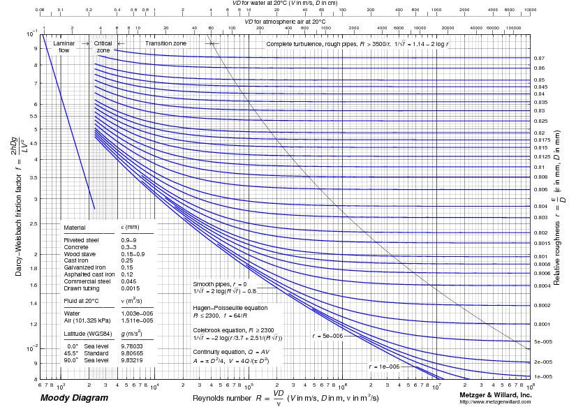
41 Evaluation of frictional pressure drop in ducts The Darcy-Weisbach equation is one of the most commonly used equations for estimating frictional pressure drops in internal flows. This equation is given by: 2 V p f 2 where f is the dimensionless friction factor, L is the length of the duct and D is the diameter in case of a circular duct and hydraulic diameter in case of a non-circular duct. The friction factor is a function of Reynolds number, Re D = ρvd/ and the relative surface roughness of the pipe or duct surface in contact with the fluid. For turbulent flow, the friction factor can be evaluated using the empirical correlation suggested by Colebrook and White is used, the correlation is given by: where is the average surface roughness of inner duct expressed in same units as the diameter D. f L D ( ) log 10[ ] f 3.7 D (Re D) f
42 Reynolds identified two types of fluid flow in 1883 by observing the behavior of a stream of dye in a water flow: laminar flow and turbulent flow. He also discovered that the ratio of inertial to viscous forces is the criterion that distinguishes these two types of fluid flow. This dimensionless parameter is now widely known as Reynolds number Re, or Re = vl/ where density of fluid, (kg /m 3 ) v velocity of fluid, (m/s) L characteristic length, ft (m) viscosity or absolute viscosity, lb / ft s (N s/m 2 )
43 For Laminar flow Parabolic profile For turbulent flow

44 Average surface roughness of commonly used duct materials In general in air conditioning ducts, the fluid flow is turbulent. It is seen from the above equation that when the flow is turbulent, the friction factor is a function of Reynolds number, hydraulic diameter and inner surface roughness of the duct material. Table 2 shows absolute roughness values of some of the materials commonly used in air conditioning. Of the different materials, the GI sheet material is very widely used for air conditioning ducts. Taking GI as the reference material and properties of air at 20 o C and 1 atm. pressure, the frictional pressure drop in a circular duct is given by: p f Q D air L (N/ m2 )
45 Dynamic losses in ducts Dynamic pressure loss takes place whenever there is a change in either the velocity or direction of airflow due to the use of a variety of bends and fittings in air conditioning ducts. Some of the commonly used fittings are: enlargements, contractions, elbows, branches, dampers etc. Normally these fittings and bends are rather short in length (< 1 m), the major pressure drop as air flows through these fittings is not because of viscous drag (friction) but due to momentum change. In turbulent flows, the dynamic loss is proportional to square 2 of velocity. Hence these are expressed as: V p d K 2 where K is the dynamic loss coefficient, which is normally obtained from experiments
46 Sometimes, an equivalent length L eq is defined to estimate the dynamic pressure loss through bends and fittings. The dynamic pressure loss is obtained from the equivalent length and the frictional pressure drop equation or chart, i.e., p d K( V 2 2 ) ( f. L D eq eq )( V 2 2 ) where f is the friction factor and L eq is the equivalent length
47 Design Velocity In supply main ducts v d,max usually does not exceeds 3000 fpm (15 m/s). Airflow noise must be checked at dampers, elbows, and branch takeoffs to satisfy the indoor NC range. In buildings with more demanding noise control criteria, such as hotels, apartments, and hospital wards, in supply main ducts usually v d,max 2000 to 2500 fpm (10 to 12.5 m/s), in return main ducts v d,max 1600 fpm (8 m/s), and in branch ducts v d,max 1200 fpm (6 m/s).
48 Turns, bends or elbows: The most common type of bends used in air conditioning ducts are 90 o turns shown in the Fig. A. Fig. B denotes turning vane to reduce turning loss. Fig. A, airflow through a 90 ⁰ bend (elbow) Fig. B, Use of turning vanes in a 90⁰ bend (elbow)
49 Branch take-offs & Branch entries Figure - A branch take-off Figure - A branch entry
50 FITTING LOSS COEFFICIENTS
51 Sudden Enlargement/Contraction sudden enlargement sudden contraction
52
53

54 Friction Chart for Round Duct ( = 1.2 kg/m 3 and ε= 0.09 mm)
55
56 Deficient System Performance with System Effect Ignored ( ) ( )Establishment of Uniform Velocity Profile in Straight Fan Outlet Duct(Adapted by permission AMCA Publication201)
57 Flow Resistances Connected in Series
58 Flow Resistances Connected in Parallel
59 Velocity method Select suitable velocities in the main and branch ducts Find the diameters of main and branch ducts from airflow rates and velocities for circular ducts. For rectangular ducts, find the cross-sectional area from flow rate and velocity, and then by fixing the aspect ratio, find the two sides of the rectangular duct From the velocities and duct dimensions obtained in the previous step, find the frictional pressure drop for main and branch ducts using friction chart or equation. From the duct layout, dimensions and airflow rates, find the dynamic pressure losses for all the bends and fittings Select a fan that can provide sufficient FTP for the index run Balancing dampers have to be installed in each run. The damper in the index run is left completely open, while the other dampers are throttled to reduce the flow rate to the required design values.
60 Using the following figure shows a typical duct layout. Design the duct system using Velocity method,
61
62
63
64
65 The velocity method is one of the simplest ways of designing the duct system for both supply and return air. However, the application of this method requires selection of suitable velocities in different duct runs, which requires experience. Wrong selection of velocities can lead to very large ducts, which, occupy large building space and increases the cost, or very small ducts which lead to large pressure drop and hence necessitates the selection of a large fan leading to higher fan cost and running cost. In addition, the method is not very efficient as it requires partial closing of all the dampers except the one in the index run, so that the total pressure drop in each run will be same.
66 Equal friction method In this method the frictional pressure drop per unit length in the main and branch ducts (Δp f /L) are kept same, i.e., Δp Δp Δp Δp f f f f ( ) A = ( ) B = ( ) C = ( ) D L L L L =...
67 Equal friction method is simple and is most widely used conventional method. This method usually yields a better design than the velocity method as most of the available pressure drop is dissipated as friction in the duct runs, rather than in the balancing dampers. This method is generally suitable when the ducts are not too long, and it can be used for both supply and return ducts. However, similar to velocity method, the equal friction method also requires partial closure of dampers in all but the index run, which may generate noise. If the ducts are too long then the total pressure drop will be high and due to dampering, ducts near the fan get overpressurized.
68 For example, let the duct run A-C-G-H be the index run and the total pressure drop in the index run is 100 Pa. If the pressure drop in the shortest duct run (say A-B) is 10 Pa, then the damper in this run has to be closed to provide an additional pressure drop of 90 Pa, so that the required airflow rate to the conditioned zone 1 can be maintained. Similarly the dampers in the other duct runs also have to be closed partially, so that the total pressure drop with damper partially closed in each run will be equal to the pressure drop in the index run with its damper left open fully.
69 Q N = Q + Q + Q + Q + Q = Q A i i=1
70 From the airflow rate and (Δp f /L) the equivalent diameter of the main duct (D eq,a ) can be obtained either from the friction chart or using the frictional pressure drop equation, i.e., D Q A eq, A = ( ) Δp f Since the frictional pressure drop per unit length is same for all the duct runs, the equivalent diameters of the other duct runs, B to I are obtained from the equation: Q Q Q ( 973) = ( ) = ( ) C= 4. D eq A ( D eq L ) B A D eq
71 If the ducts are rectangular, then the two sides of the rectangular duct of each run are obtained from the equivalent diameter of that run and by fixing aspect ratio as explained earlier. Thus the dimensions of the all the duct runs can be obtained. The velocity of air through each duct is obtained from the volumetric flow rate and the cross-sectional area. Next from the dimensions of the ducts in each run, the total frictional pressure drop of that run is obtained by multiplying the frictional pressure drop per unit length and the length, i.e., Δp f f Δ Pf, A = ( ) A. LA f, B B B L Δp Δ P = ( ). L L
72 Next the dynamic pressure losses in each duct run are obtained based on the type of bends or fittings used in that run. Next the total pressure drop in each duct run is obtained by summing up the frictional and dynamic losses of that run, i.e., ΔP A = Δp f,a + Δp d,a ΔP B = Δp f,b + Δp d,b Next the fan is selected to suit the index run with the highest pressure loss. Dampers are installed in all the duct runs to balance the total pressure loss.
73 Using the following figure shows a typical duct layout. Design the duct system using Equal Friction method,
74
75
76
77 From the example, it is seen that the Velocity method results in larger duct diameters due to the velocities selected in branch and downstream. However, the required FTP is lower in case of velocity method due to larger ducts. Equal Friction method results in smaller duct diameters, but larger FTP. Compared to velocity method, the required dampering is more at outlet 1 and less at outlet 2 in case of equal friction method.
78 Performance of duct systems For the duct system with air in turbulent flow, the total pressure loss (Δp t ) is proportional to the square of flow rate; i.e., Total pressure drop, or, total pressure drop, P t (Q) ΔP t 2 = C( Q ) 2 Variation of total pressure drop with flow rate for a given duct system
79 Fan To overcome the fluid friction and the resulting head, a fan is required in air conditioning systems. When a fan is introduced into the duct through which air is flowing, then the static and total pressures at the section where the fan is located. This rise is called as Fan Total Pressure (FTP). Then the required power input to the fan is given by: Qair. FTP Wfan = η The FTP should be such that it - overcomes the pressure drop of air as it flows through the duct and the air finally enters the conditioned space with sufficient momentum so that a good air distribution can be obtained in the conditioned space. Evaluation of FTP is important in the selection of a suitable fan for a given application. It can be easily shown that when applied between any two sections 1 and 2 of the duct, in which the fan is located, 2 2 the FTP is given by: ( V2 V1 ) FTP ( p2 p1) g( z2 z1) gh 2g fan 1
80 Fan A fan is the prime mover of an air system or ventilation system. It moves the air and provides continuous airflow so that the conditioned air, space air, exhaust air, or outdoor air can be transported from one location to another through air ducts or other air passages. A fan is also a turbomachine in which air is usually compressed at a compression ratio R com not greater than The compression ratio, dimensionless, is defined as where P dis discharge pressure at outlet of compressor or fan, lbf/in. 2 abs. or psia (kpa abs.) P suc suction pressure at inlet of compressor or fan, psia (kpa abs.)
81 Fan Fan Capacity or Volume Flow Rate Fan Pressure Air Temperature Increase through Fan Fan Power and Fan Efficiency Fan Performance Curves
82 ypes of fans: (a) centrifugal; (b) axial; (c) crossflow
83
84 In a backward-curved or backward-inclined centrifugal fan, the blade tip inclines away from the direction of rotation of the impeller. The 2 angle of a backward-curved centrifugal fan is less than 90. The impeller of a backward-curved centrifugal fan usually consists of 8 to 16 blades. For greater efficiency, the shape of the blades is often streamlined to provide minimum flow separation and, therefore, minimum energy losses. Backwardcurved centrifugal fans with such blades are called airfoil fans, as distinguished from fans with sheet-metal blades. The blades in a backward-curved fan are always longer than those of a forwardcurved fan. A volute or scroll casing is used. Radial-Bladed Fans The blades in a radial-bladed centrifugal fan are either straight or curved at the blade inlet. The blade tip or blade outlet is always radial; that is, 2 90, as shown. Usually, there are 6 to 10 blades in a radial-bladed impeller. The construction of the radial blades is comparatively simple.
85 AXIAL FANS Types of Axial Fans For an axial fan, a parameter called the hub ratio is closely related to its characteristics. Hub ratio R hub is defined as the ratio of hub diameter D hub, in ft (m), to the tip-to-tip blade diameter or diameter of impeller D bt, in ft (m),
86 Propeller Fans. an impeller having 3 to 6 blades is mounted within a circular ring or an orifice plate. The blades are generally made of steel or molded plastic and sometimes may increase in width at the blade tip. If the impeller is mounted inside an orifice plate, the direction of airflow at the blade tip will not be parallel to the axle. Eddies may form at the blade tips. Propeller fans are usually operated at very low static pressure with large volume flow. They often have a hub ratio R hub 0.15.
87 Tube-Axial Fans. The impeller of a tube-axial fan usually has 6 to 9 blades. It is mounted within a cylindrical casing. The blades can be airfoil blades or curved sheet metal. Airfoil blades usually made of cast aluminum or aluminum alloy. The hub ratio R hub is generally less than 0.3, and the clearance between the blade tip and the casing is significantly closer than in propeller fans. Vane-Axial Fans. The impeller of a vane-axial fan has 8 to 16 blades, usually airfoil blades. The hub ratio is generally equal to or greater than 0.3 in order to increase the fan total pressure. Another important characteristic of vane-axial fans is the installation of fixed guide vanes downstream from the impeller. These curved vanes are designed to remove swirl from the air, straighten the airflow, and convert a portion of the velocity pressure of the rotating airflow to static pressure.
88 Airflow rate, Static pressure rise, Fan power input, Fan Laws Q W 2 ρv ΔP S 2 2 V Q ( P S ) Q ( ) 2 Law 1: Density of air ρ remains constant and the speed ω varies: Q 2 3 ; ΔP S ω and W Law 2 : Airflow rate Q Q CONST remains constant and the density ρ varies: ; W and P S Law 3 : Static pressure rise ΔP s remains constant and density ρ varies : Q 1 1 ; ΔP s =const ; ω and ρ W 1
89 Interaction between fan and duct system Fan and duct performance curves and balance points
90
91
92
93
94 Thank You
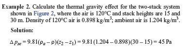
95 When an air duct system has an elevation difference and the air temperature inside the air duct is different from the ambient air temperature, the stack effect exists. It affects airflow at different elevations. Form Equation (2), the thermal gravity effect for each nonhorizontal duct with a density other than that of ambient air is determined by the following equation : Stack effect Δp se = g(ρ a -ρ)( z 2 z 1 ) Where Δp se = thermal gravity effect, Pa z 1 and z 2 = elevation from datum in direction airflow, m ρ a = density of ambient air, kg/m 3 ρ = density of air gas within duct, kg/m 3 g = 9.81 = gravitational acceleration, m/s 2
96
97
98 For the system shown in Figure 3, the direction of air movement created by the thermal gravity effect depends on the initiating force (e.g., fans, wind, opening and closing doors, turning equipment on and off). If for any reason air starts to enter the left stack (Figure 3A), it creates a buoyancy effect in the right stack. On the other hand, if flow starts to enter the right stack (Figure 3B), it creates a buoyancy effect in the left stack. In both cases, the produced thermal gravity effect is stable and depends on stack height and magnitude of heating. The starting direction of flow is important when using natural convection for ventilation.
99
100
101
102 Static Regain Method This method is commonly used for high velocity systems with long duct runs, especially in large systems. In this method the static pressure is maintained same before each terminal or branch. Static Regain method yields a more balanced system and does not call for unnecessary dampering. However, as velocity reduces in the direction of airflow, the duct size may increase in the airflow direction. Also the velocity at the exit of the longer duct runs may become too small for proper air distribution in the conditioned space.

103 The purpose of the Static Regain method is to create equal static pressures at successive junctions which will presumably cause equal flows in branches that are identical "a branch might lead to a di}user or to an entire duct subsystem. When this principle is applied to a main duct with identical branches leading to identical diffusers equal air quantities will be delivered without the need to throttle the flow in the upstream branches The same principle is utilized to provide equal pressures at the take off points of a duct riser that serves several which means that the duct sizing of each can be considered typical.
104 Design Procedures Velocity in the main duct leaving the fan is selected first. Velocities in each successive runs are reduced such that the gain in static pressure due to reduction in velocity pressure equals the frictional pressure drop in the next duct section. Thus the static pressure before each terminal or branch is maintained constant. For example, Figure shows a part of the duct run with two sections 1 and 2 before two branch take-offs. The velocity at 1 is greater than that at 2, such that the static pressure is same at 1 and 2. Then using the static regain factor, one can write: Δp f,2 + Δp d,2 =R(p ν,1 p ν,2 )
105 where Δp f,2 and Δp d,2 are the frictional and dynamic losses between 1 and 2, and p v,1 and p v,2 are the velocity pressures at 1 and 2 respectively. p s p =, 1 s,2 Principle of static regain method
106 If section 1 is the outlet of the fan, then its dimensions are known from the flow rate and velocity (initially selected), however, since both the dimensions and velocity at section 2 are not known, a trial-and-error method has to be followed to solve the above equation, which gives required dimensions of the section at 2. The procedure is followed in the direction of airflow, and the dimensions of the downstream ducts are obtained. As before, the total pressure drop is obtained from the pressure drop in the longest run and a fan is accordingly selected.
107
Lesson 37 Transmission Of Air In Air Conditioning Ducts
 Lesson 37 Transmission Of Air In Air Conditioning Ducts Version 1 ME, IIT Kharagpur 1 The specific objectives of this chapter are to: 1. Describe an Air Handling Unit (AHU) and its functions (Section 37.1).
Cdesign must consider (1) space availability, (2) space air diffusion,
 space availability, (2) space air diffusion,") Related Commercial Resources CHAPTER 35 DUCT DESIGN BERNOULLI EQUATION... 35.1 Head and Pressure... 35.2 SYSTEM ANALYSIS... 35.2 Pressure Changes in System... 35.5 FLUID RESISTANCE... 35.6 Friction Losses...
Related Commercial Resources CHAPTER 35 DUCT DESIGN BERNOULLI EQUATION... 35.1 Head and Pressure... 35.2 SYSTEM ANALYSIS... 35.2 Pressure Changes in System... 35.5 FLUID RESISTANCE... 35.6 Friction Losses...
Cdesign must consider (1) space availability, (2) space air
 space availability, (2) space air") ASHRAE Fundimental CHAPChTER 32 DUCT DESIGN Bernoulli Equation.... 32.1 Head and Pressure.... 32.2 SYSTEM ANALYSIS.... 32.2 Pressure Changes in System.... 32.6 FLUID RESISTANCE.... 32.7 Friction Losses....
ASHRAE Fundimental CHAPChTER 32 DUCT DESIGN Bernoulli Equation.... 32.1 Head and Pressure.... 32.2 SYSTEM ANALYSIS.... 32.2 Pressure Changes in System.... 32.6 FLUID RESISTANCE.... 32.7 Friction Losses....
HVAC Clinic. Duct Design
 HVAC Clinic Duct Design Table Of Contents Introduction... 3 Fundamentals Of Duct Design... 3 Pressure Changes In A System... 8 Example 1... 13 Duct Design Methods... 15 Example 2... 15 Introduction The
Lesson 6 Review of fundamentals: Fluid flow
 Lesson 6 Review of fundamentals: Fluid flow The specific objective of this lesson is to conduct a brief review of the fundamentals of fluid flow and present: A general equation for conservation of mass
Duct Design and Air Distribution Systems
 Duct Design and Air Distribution Systems Introduction The chief requirements of an air conditioning duct system are: It should convey specified rates of air flow to prescribed locations It should be economical
Piping Systems and Flow Analysis (Chapter 3)
") Piping Systems and Flow Analysis (Chapter 3) 2 Learning Outcomes (Chapter 3) Losses in Piping Systems Major losses Minor losses Pipe Networks Pipes in series Pipes in parallel Manifolds and Distribution
Piping Systems and Flow Analysis (Chapter 3) 2 Learning Outcomes (Chapter 3) Losses in Piping Systems Major losses Minor losses Pipe Networks Pipes in series Pipes in parallel Manifolds and Distribution
Applied Fluid Mechanics
 Applied Fluid Mechanics 1. The Nature of Fluid and the Study of Fluid Mechanics 2. Viscosity of Fluid 3. Pressure Measurement 4. Forces Due to Static Fluid 5. Buoyancy and Stability 6. Flow of Fluid and
Chapter 8: Flow in Pipes
 Objectives 1. Have a deeper understanding of laminar and turbulent flow in pipes and the analysis of fully developed flow 2. Calculate the major and minor losses associated with pipe flow in piping networks
FE Fluids Review March 23, 2012 Steve Burian (Civil & Environmental Engineering)
") Topic: Fluid Properties 1. If 6 m 3 of oil weighs 47 kn, calculate its specific weight, density, and specific gravity. 2. 10.0 L of an incompressible liquid exert a force of 20 N at the earth s surface.
Topic: Fluid Properties 1. If 6 m 3 of oil weighs 47 kn, calculate its specific weight, density, and specific gravity. 2. 10.0 L of an incompressible liquid exert a force of 20 N at the earth s surface.
AEROSPACE ENGINEERING DEPARTMENT. Second Year - Second Term ( ) Fluid Mechanics & Gas Dynamics
 Fluid Mechanics & Gas Dynamics") AEROSPACE ENGINEERING DEPARTMENT Second Year - Second Term (2008-2009) Fluid Mechanics & Gas Dynamics Similitude,Dimensional Analysis &Modeling (1) [7.2R*] Some common variables in fluid mechanics include:
AEROSPACE ENGINEERING DEPARTMENT Second Year - Second Term (2008-2009) Fluid Mechanics & Gas Dynamics Similitude,Dimensional Analysis &Modeling (1) [7.2R*] Some common variables in fluid mechanics include:
ME 305 Fluid Mechanics I. Part 8 Viscous Flow in Pipes and Ducts. Flow in Pipes and Ducts. Flow in Pipes and Ducts (cont d)
") ME 305 Fluid Mechanics I Flow in Pipes and Ducts Flow in closed conduits (circular pipes and non-circular ducts) are very common. Part 8 Viscous Flow in Pipes and Ducts These presentations are prepared
ME 305 Fluid Mechanics I Flow in Pipes and Ducts Flow in closed conduits (circular pipes and non-circular ducts) are very common. Part 8 Viscous Flow in Pipes and Ducts These presentations are prepared
FE Exam Fluids Review October 23, Important Concepts
 FE Exam Fluids Review October 3, 013 mportant Concepts Density, specific volume, specific weight, specific gravity (Water 1000 kg/m^3, Air 1. kg/m^3) Meaning & Symbols? Stress, Pressure, Viscosity; Meaning
Reynolds, an engineering professor in early 1880 demonstrated two different types of flow through an experiment:
 7 STEADY FLOW IN PIPES 7.1 Reynolds Number Reynolds, an engineering professor in early 1880 demonstrated two different types of flow through an experiment: Laminar flow Turbulent flow Reynolds apparatus
F L U I D S Y S T E M D Y N A M I C S
 F L U I D S Y S T E M D Y N A M I C S T he proper design, construction, operation, and maintenance of fluid systems requires understanding of the principles which govern them. These principles include
UNIT II CONVECTION HEAT TRANSFER
 UNIT II CONVECTION HEAT TRANSFER Convection is the mode of heat transfer between a surface and a fluid moving over it. The energy transfer in convection is predominately due to the bulk motion of the fluid
Chapter 3 NATURAL CONVECTION
 Fundamentals of Thermal-Fluid Sciences, 3rd Edition Yunus A. Cengel, Robert H. Turner, John M. Cimbala McGraw-Hill, 2008 Chapter 3 NATURAL CONVECTION Mehmet Kanoglu Copyright The McGraw-Hill Companies,
10.52 Mechanics of Fluids Spring 2006 Problem Set 3
 10.52 Mechanics of Fluids Spring 2006 Problem Set 3 Problem 1 Mass transfer studies involving the transport of a solute from a gas to a liquid often involve the use of a laminar jet of liquid. The situation
ME 305 Fluid Mechanics I. Chapter 8 Viscous Flow in Pipes and Ducts
 ME 305 Fluid Mechanics I Chapter 8 Viscous Flow in Pipes and Ducts These presentations are prepared by Dr. Cüneyt Sert Department of Mechanical Engineering Middle East Technical University Ankara, Turkey
CHAPTER EIGHT P U M P I N G O F L I Q U I D S
 CHAPTER EIGHT P U M P I N G O F L I Q U I D S Pupmps are devices for supplying energy or head to a flowing liquid in order to overcome head losses due to friction and also if necessary, to raise liquid
Twin City Fan Companies. Fan System Effects
 Fan System Effects Outline Fan Testing Review Definition of System Effect Old ASHRAE guidelines AMCA 201 System Effect Factors Examples Demonstration Aimed at the fan system designer There are two goals:
Viscous Flow in Ducts
 Dr. M. Siavashi Iran University of Science and Technology Spring 2014 Objectives 1. Have a deeper understanding of laminar and turbulent flow in pipes and the analysis of fully developed flow 2. Calculate
FACULTY OF CHEMICAL & ENERGY ENGINEERING FLUID MECHANICS LABORATORY TITLE OF EXPERIMENT: MINOR LOSSES IN PIPE (E4)
") FACULTY OF CHEMICAL & ENERGY ENGINEERING FLUID MECHANICS LABORATORY TITLE OF EXPERIMENT: MINOR LOSSES IN PIPE (E4) 1 1.0 Objectives The objective of this experiment is to calculate loss coefficient (K
FACULTY OF CHEMICAL & ENERGY ENGINEERING FLUID MECHANICS LABORATORY TITLE OF EXPERIMENT: MINOR LOSSES IN PIPE (E4) 1 1.0 Objectives The objective of this experiment is to calculate loss coefficient (K
Experiment- To determine the coefficient of impact for vanes. Experiment To determine the coefficient of discharge of an orifice meter.
 SUBJECT: FLUID MECHANICS VIVA QUESTIONS (M.E 4 th SEM) Experiment- To determine the coefficient of impact for vanes. Q1. Explain impulse momentum principal. Ans1. Momentum equation is based on Newton s
Mechanical Engineering Programme of Study
 Mechanical Engineering Programme of Study Fluid Mechanics Instructor: Marios M. Fyrillas Email: eng.fm@fit.ac.cy SOLVED EXAMPLES ON VISCOUS FLOW 1. Consider steady, laminar flow between two fixed parallel
Water Circuit Lab. The pressure drop along a straight pipe segment can be calculated using the following set of equations:
 Water Circuit Lab When a fluid flows in a conduit, there is friction between the flowing fluid and the pipe walls. The result of this friction is a net loss of energy in the flowing fluid. The fluid pressure
1-Reynold s Experiment
 Lect.No.8 2 nd Semester Flow Dynamics in Closed Conduit (Pipe Flow) 1 of 21 The flow in closed conduit ( flow in pipe ) is differ from this occur in open channel where the flow in pipe is at a pressure
Chapter 8: Flow in Pipes
 8-1 Introduction 8-2 Laminar and Turbulent Flows 8-3 The Entrance Region 8-4 Laminar Flow in Pipes 8-5 Turbulent Flow in Pipes 8-6 Fully Developed Pipe Flow 8-7 Minor Losses 8-8 Piping Networks and Pump
Chapter Four fluid flow mass, energy, Bernoulli and momentum
 4-1Conservation of Mass Principle Consider a control volume of arbitrary shape, as shown in Fig (4-1). Figure (4-1): the differential control volume and differential control volume (Total mass entering
ME332 FLUID MECHANICS LABORATORY (PART II)
") ME332 FLUID MECHANICS LABORATORY (PART II) Mihir Sen Department of Aerospace and Mechanical Engineering University of Notre Dame Notre Dame, IN 46556 Version: April 2, 2002 Contents Unit 5: Momentum transfer
ME332 FLUID MECHANICS LABORATORY (PART II) Mihir Sen Department of Aerospace and Mechanical Engineering University of Notre Dame Notre Dame, IN 46556 Version: April 2, 2002 Contents Unit 5: Momentum transfer
Introduction to Turbomachinery
 1. Coordinate System Introduction to Turbomachinery Since there are stationary and rotating blades in turbomachines, they tend to form a cylindrical form, represented in three directions; 1. Axial 2. Radial
Part A: 1 pts each, 10 pts total, no partial credit.
 Part A: 1 pts each, 10 pts total, no partial credit. 1) (Correct: 1 pt/ Wrong: -3 pts). The sum of static, dynamic, and hydrostatic pressures is constant when flow is steady, irrotational, incompressible,
COURSE NUMBER: ME 321 Fluid Mechanics I 3 credit hour. Basic Equations in fluid Dynamics
 COURSE NUMBER: ME 321 Fluid Mechanics I 3 credit hour Basic Equations in fluid Dynamics Course teacher Dr. M. Mahbubur Razzaque Professor Department of Mechanical Engineering BUET 1 Description of Fluid
Chapter 6. Losses due to Fluid Friction
 Chapter 6 Losses due to Fluid Friction 1 Objectives ä To measure the pressure drop in the straight section of smooth, rough, and packed pipes as a function of flow rate. ä To correlate this in terms of
Heat Transfer Convection
 Heat ransfer Convection Previous lectures conduction: heat transfer without fluid motion oday (textbook nearly 00 pages) Convection: heat transfer with fluid motion Research methods different Natural Convection
LECTURE-11 FAN AND DUCT SYSTEM-2
 L ecturer: -D D r. E sam M ejbil A bid Subject: A ir Conditioning and R efrigeration Year: Y Fourth B.Sc. D E P A R TM E N O F M E CH A N ICA L E N G IN E E R IN B abylon U niversity College of E ngineering
FLUID MECHANICS PROF. DR. METİN GÜNER COMPILER
 FLUID MECHANICS PROF. DR. METİN GÜNER COMPILER ANKARA UNIVERSITY FACULTY OF AGRICULTURE DEPARTMENT OF AGRICULTURAL MACHINERY AND TECHNOLOGIES ENGINEERING 1 5. FLOW IN PIPES 5.1.3. Pressure and Shear Stress
2 Internal Fluid Flow
 Internal Fluid Flow.1 Definitions Fluid Dynamics The study of fluids in motion. Static Pressure The pressure at a given point exerted by the static head of the fluid present directly above that point.
EXPERIMENT No.1 FLOW MEASUREMENT BY ORIFICEMETER
 EXPERIMENT No.1 FLOW MEASUREMENT BY ORIFICEMETER 1.1 AIM: To determine the co-efficient of discharge of the orifice meter 1.2 EQUIPMENTS REQUIRED: Orifice meter test rig, Stopwatch 1.3 PREPARATION 1.3.1
UNIT I FLUID PROPERTIES AND STATICS
 SIDDHARTH GROUP OF INSTITUTIONS :: PUTTUR Siddharth Nagar, Narayanavanam Road 517583 QUESTION BANK (DESCRIPTIVE) Subject with Code : Fluid Mechanics (16CE106) Year & Sem: II-B.Tech & I-Sem Course & Branch:
Applied Fluid Mechanics
 Applied Fluid Mechanics 1. The Nature of Fluid and the Study of Fluid Mechanics 2. Viscosity of Fluid 3. Pressure Measurement 4. Forces Due to Static Fluid 5. Buoyancy and Stability 6. Flow of Fluid and
Figure 3: Problem 7. (a) 0.9 m (b) 1.8 m (c) 2.7 m (d) 3.6 m
 0.9 m (b) 1.8 m (c) 2.7 m (d) 3.6 m") 1. For the manometer shown in figure 1, if the absolute pressure at point A is 1.013 10 5 Pa, the absolute pressure at point B is (ρ water =10 3 kg/m 3, ρ Hg =13.56 10 3 kg/m 3, ρ oil = 800kg/m 3 ): (a)
1. For the manometer shown in figure 1, if the absolute pressure at point A is 1.013 10 5 Pa, the absolute pressure at point B is (ρ water =10 3 kg/m 3, ρ Hg =13.56 10 3 kg/m 3, ρ oil = 800kg/m 3 ): (a)
Convective Mass Transfer
 Convective Mass Transfer Definition of convective mass transfer: The transport of material between a boundary surface and a moving fluid or between two immiscible moving fluids separated by a mobile interface
Applied Fluid Mechanics
 Applied Fluid Mechanics 1. The Nature of Fluid and the Study of Fluid Mechanics 2. Viscosity of Fluid 3. Pressure Measurement 4. Forces Due to Static Fluid 5. Buoyancy and Stability 6. Flow of Fluid and
Fluid Mechanics. du dy
 FLUID MECHANICS Technical English - I 1 th week Fluid Mechanics FLUID STATICS FLUID DYNAMICS Fluid Statics or Hydrostatics is the study of fluids at rest. The main equation required for this is Newton's
Laminar and turbulent flows
 Ventilation 0 Duct Design Vladimír Zmrhal (room no. 84) http://users.fs.cvut.cz/~zmrhavla/index.htm Dpt. Of Environmental Engineering Laminar and turbulent flos Reynolds number d Re = ν laminar flo Re
CHAPTER 3 BASIC EQUATIONS IN FLUID MECHANICS NOOR ALIZA AHMAD
 CHAPTER 3 BASIC EQUATIONS IN FLUID MECHANICS 1 INTRODUCTION Flow often referred as an ideal fluid. We presume that such a fluid has no viscosity. However, this is an idealized situation that does not exist.
FLOW IN PIPES. Mark J McCready University of Notre Dame July 24, chemeprof.com
 FLOW IN PIPES Mark J McCready University of Notre Dame July 24, 2017 OVERVIEW This lecture will provide the simplest framework to explain The three forces at that are important to fluid flow in pipes The
 Ventilation 5 Fans Vladimír Zmrhal (room no. 814) http://users.fs.cvut.cz/~zmrhavla/index.htm Dpt. Of Environmental Engineering 1 Introduction Fans air pump that creates a pressure difference and causes
9. Pumps (compressors & turbines) Partly based on Chapter 10 of the De Nevers textbook.
 Partly based on Chapter 10 of the De Nevers textbook.") Lecture Notes CHE 31 Fluid Mechanics (Fall 010) 9. Pumps (compressors & turbines) Partly based on Chapter 10 of the De Nevers textbook. Basics (pressure head, efficiency, working point, stability) Pumps
Lecture Notes CHE 31 Fluid Mechanics (Fall 010) 9. Pumps (compressors & turbines) Partly based on Chapter 10 of the De Nevers textbook. Basics (pressure head, efficiency, working point, stability) Pumps
Hydraulics. B.E. (Civil), Year/Part: II/II. Tutorial solutions: Pipe flow. Tutorial 1
, Year/Part: II/II. Tutorial solutions: Pipe flow. Tutorial 1") Hydraulics B.E. (Civil), Year/Part: II/II Tutorial solutions: Pipe flow Tutorial 1 -by Dr. K.N. Dulal Laminar flow 1. A pipe 200mm in diameter and 20km long conveys oil of density 900 kg/m 3 and viscosity
Hydraulics B.E. (Civil), Year/Part: II/II Tutorial solutions: Pipe flow Tutorial 1 -by Dr. K.N. Dulal Laminar flow 1. A pipe 200mm in diameter and 20km long conveys oil of density 900 kg/m 3 and viscosity
2 Navier-Stokes Equations
 1 Integral analysis 1. Water enters a pipe bend horizontally with a uniform velocity, u 1 = 5 m/s. The pipe is bended at 90 so that the water leaves it vertically downwards. The input diameter d 1 = 0.1
Pressure and Flow Characteristics
 Pressure and Flow Characteristics Continuing Education from the American Society of Plumbing Engineers August 2015 ASPE.ORG/ReadLearnEarn CEU 226 READ, LEARN, EARN Note: In determining your answers to
Major and Minor Losses
 Abstract Major and Minor Losses Caitlyn Collazo, Team 2 (1:00 pm) A Technovate fluid circuit system was used to determine the pressure drop across a pipe section and across an orifice. These pressure drops
COURSE CODE : 3072 COURSE CATEGORY : B PERIODS/ WEEK : 5 PERIODS/ SEMESTER : 75 CREDIT : 5 TIME SCHEDULE
 COURSE TITLE : FLUID MECHANICS COURSE CODE : 307 COURSE CATEGORY : B PERIODS/ WEEK : 5 PERIODS/ SEMESTER : 75 CREDIT : 5 TIME SCHEDULE MODULE TOPIC PERIOD 1 Properties of Fluids 0 Fluid Friction and Flow
The diagram below. to the by the. outlet into. calculation. Since TRANSMISSION VIA STRUCTURE. Vibration Via Supports Duct Breakout
 NOISE CONTROL IN VENTILATING SYSTEMS INTRODUCTION The diagram below shows the various noise sources and transmission paths of plant rooms and ventilation systems. For the ventilation system this can be
Hydraulics and hydrology
 Hydraulics and hydrology - project exercises - Class 4 and 5 Pipe flow Discharge (Q) (called also as the volume flow rate) is the volume of fluid that passes through an area per unit time. The discharge
FAN TERMINOLOGY. t = 1.2 kg/m 3 (Standard air density at 20 C and 1013mb. V = duct air velocity, m/s.
 +7 (0)1 55 1077 +7 (0)1 55 797 FAN TERMINOLOGY These notes are designed to explain some of the terms that are used in describing the characteristics of fans and the relationship between the fan performance
Applied Fluid Mechanics
 Applied Fluid Mechanics 1. The Nature of Fluid and the Study of Fluid Mechanics 2. Viscosity of Fluid 3. Pressure Measurement 4. Forces Due to Static Fluid 5. Buoyancy and Stability 6. Flow of Fluid and
Chapter 10 Flow in Conduits
 Chapter 10 Flow in Conduits 10.1 Classifying Flow Laminar Flow and Turbulent Flow Laminar flow Unpredictable Turbulent flow Near entrance: undeveloped developing flow In developing flow, the wall shear
STEADY FLOW THROUGH PIPES DARCY WEISBACH EQUATION FOR FLOW IN PIPES. HAZEN WILLIAM S FORMULA, LOSSES IN PIPELINES, HYDRAULIC GRADE LINES AND ENERGY
 STEADY FLOW THROUGH PIPES DARCY WEISBACH EQUATION FOR FLOW IN PIPES. HAZEN WILLIAM S FORMULA, LOSSES IN PIPELINES, HYDRAULIC GRADE LINES AND ENERGY LINES 1 SIGNIFICANCE OF CONDUITS In considering the convenience
Lecture 22. Mechanical Energy Balance
 Lecture 22 Mechanical Energy Balance Contents Exercise 1 Exercise 2 Exercise 3 Key Words: Fluid flow, Macroscopic Balance, Frictional Losses, Turbulent Flow Exercise 1 It is proposed to install a fan to
150A Review Session 2/13/2014 Fluid Statics. Pressure acts in all directions, normal to the surrounding surfaces
 Fluid Statics Pressure acts in all directions, normal to the surrounding surfaces or Whenever a pressure difference is the driving force, use gauge pressure o Bernoulli equation o Momentum balance with
Experiment (4): Flow measurement
: Flow measurement") Experiment (4): Flow measurement Introduction: The flow measuring apparatus is used to familiarize the students with typical methods of flow measurement of an incompressible fluid and, at the same time
Experiment (4): Flow measurement Introduction: The flow measuring apparatus is used to familiarize the students with typical methods of flow measurement of an incompressible fluid and, at the same time
M E 320 Professor John M. Cimbala Lecture 23
 M E 320 Professor John M. Cimbala Lecture 23 Today, we will: Discuss diffusers and do an example problem Begin discussing pumps, and how they are analyzed in pipe flow systems D. Diffusers 1. Introduction.
FLUID MECHANICS PROF. DR. METİN GÜNER COMPILER
 FLUID MECHANICS PROF. DR. METİN GÜNER COMPILER ANKARA UNIVERSITY FACULTY OF AGRICULTURE DEPARTMENT OF AGRICULTURAL MACHINERY AND TECHNOLOGIES ENGINEERING 1 5. FLOW IN PIPES Liquid or gas flow through pipes
Non- Iterative Technique for Balancing an. Air Distribution System
 Non- Iterative Technique for Balancing an Air Distribution System Mauro Small Thesis presented to the Faculty of Virginia Polytechnic Institute and State University in partial fulfillment of the requirements
Sound Rating of Ducted Air Moving and Conditioning Equipment
 AHRI Standard 260 (I-P) 2017 Standard for Sound Rating of Ducted Air Moving and Conditioning Equipment IMPORTANT SAFETY DISCLAIMER AHRI does not set safety standards and does not certify or guarantee the
Contents. 1 Introduction to Gas-Turbine Engines Overview of Turbomachinery Nomenclature...9
 Preface page xv 1 Introduction to Gas-Turbine Engines...1 Definition 1 Advantages of Gas-Turbine Engines 1 Applications of Gas-Turbine Engines 3 The Gas Generator 3 Air Intake and Inlet Flow Passage 3
Performance characteristics of turbo blower in a refuse collecting system according to operation conditions
 Journal of Mechanical Science and Technology 22 (2008) 1896~1901 Journal of Mechanical Science and Technology www.springerlink.com/content/1738-494x DOI 10.1007/s12206-008-0729-6 Performance characteristics
COMPUTER AIDED DESIGN OF RADIAL TIPPED CENTRIFUGAL BLOWERS AND FANS
 4 th International Conference on Mechanical Engineering, December 26-28, 21, Dhaka, Bangladesh/pp. IV 55-6 COMPUTER AIDED DESIGN OF RADIAL TIPPED CENTRIFUGAL BLOWERS AND FANS Nitin N. Vibhakar* and S.
Empirical Co - Relations approach for solving problems of convection 10:06:43
 Empirical Co - Relations approach for solving problems of convection 10:06:43 10:06:44 Empirical Corelations for Free Convection Use T f or T b for getting various properties like Re = VL c / ν β = thermal
Lecture 13 Flow Measurement in Pipes. I. Introduction
 Lecture 13 Flow Measurement in Pipes I. Introduction There are a wide variety of methods for measuring discharge and velocity in pipes, or closed conduits Many of these methods can provide very accurate
CHAPTER THREE FLUID MECHANICS
 CHAPTER THREE FLUID MECHANICS 3.1. Measurement of Pressure Drop for Flow through Different Geometries 3.. Determination of Operating Characteristics of a Centrifugal Pump 3.3. Energy Losses in Pipes under
Bernoulli and Pipe Flow
 Civil Engineering Hydraulics Mechanics of Fluids Head Loss Calculations Bernoulli and The Bernoulli equation that we worked with was a bit simplistic in the way it looked at a fluid system All real systems
R09. d water surface. Prove that the depth of pressure is equal to p +.
 Code No:A109210105 R09 SET-1 B.Tech II Year - I Semester Examinations, December 2011 FLUID MECHANICS (CIVIL ENGINEERING) Time: 3 hours Max. Marks: 75 Answer any five questions All questions carry equal
Principles of Convection
 Principles of Convection Point Conduction & convection are similar both require the presence of a material medium. But convection requires the presence of fluid motion. Heat transfer through the: Solid
Krantz Components. Twist outlet DD-N... for ceiling installation. Air distribution systems
 Krantz Components Twist outlet DD-N... for ceiling installation Air distribution systems DS E 0. Twist outlet Preliminary remarks and construction design Preliminary remarks Twist outlets for ceiling installation
CHARACTERISATION OF PRESSURE AND VELOCITY OF AIR FLOW THROUGH PERFORATED PIPE: EXPERIMENTAL AND COMPUTATIONAL APPROACH
 CHARACTERISATION OF PRESSURE AND VELOCITY OF AIR FLOW THROUGH PERFORATED PIPE: EXPERIMENTAL AND COMPUTATIONAL APPROACH *Helmisyah Ahmad Jalaludin, 2 Mohd Daniel Bakri Omar, 2 Ow Chee Seng *Faculty of Mechanical
LECTURE 6- ENERGY LOSSES IN HYDRAULIC SYSTEMS SELF EVALUATION QUESTIONS AND ANSWERS
 LECTURE 6- ENERGY LOSSES IN HYDRAULIC SYSTEMS SELF EVALUATION QUESTIONS AND ANSWERS 1. What is the head loss ( in units of bars) across a 30mm wide open gate valve when oil ( SG=0.9) flow through at a
TOTAL HEAD, N.P.S.H. AND OTHER CALCULATION EXAMPLES Jacques Chaurette p. eng., June 2003
 TOTAL HEAD, N.P.S.H. AND OTHER CALCULATION EXAMPLES Jacques Chaurette p. eng., www.lightmypump.com June 2003 Figure 1 Calculation example flow schematic. Situation Water at 150 F is to be pumped from a
UNIT II Real fluids. FMM / KRG / MECH / NPRCET Page 78. Laminar and turbulent flow
 UNIT II Real fluids The flow of real fluids exhibits viscous effect that is they tend to "stick" to solid surfaces and have stresses within their body. You might remember from earlier in the course Newtons
Basic Fluid Mechanics
 Basic Fluid Mechanics Chapter 6A: Internal Incompressible Viscous Flow 4/16/2018 C6A: Internal Incompressible Viscous Flow 1 6.1 Introduction For the present chapter we will limit our study to incompressible
SUMMER 14 EXAMINATION
 Important Instructions to examiners: 1) The answers should be examined by key words and not as word-to-word as given in the model answer scheme. 2) The model answer and the answer written by candidate
Chapter (3) Water Flow in Pipes
 Water Flow in Pipes") Chapter (3) Water Flow in Pipes Water Flow in Pipes Bernoulli Equation Recall fluid mechanics course, the Bernoulli equation is: P 1 ρg + v 1 g + z 1 = P ρg + v g + z h P + h T + h L Here, we want to study
Chapter (3) Water Flow in Pipes Water Flow in Pipes Bernoulli Equation Recall fluid mechanics course, the Bernoulli equation is: P 1 ρg + v 1 g + z 1 = P ρg + v g + z h P + h T + h L Here, we want to study
Atmospheric pressure. 9 ft. 6 ft
 Name CEE 4 Final Exam, Aut 00; Answer all questions; 145 points total. Some information that might be helpful is provided below. A Moody diagram is printed on the last page. For water at 0 o C (68 o F):
ASSESSMENT OF DESIGN METHODOLOGY AND THREE DIMENSIONAL NUMERICAL (CFD) ANALYSIS OF CENTRIFUGAL BLOWER
 ANALYSIS OF CENTRIFUGAL BLOWER") ASSESSMENT OF DESIGN METHODOLOGY AND THREE DIMENSIONAL NUMERICAL (CFD) ANALYSIS OF CENTRIFUGAL BLOWER D. R. Chaudhari 1, H. N. Patel 2 1,2 Mechanical Department, Government Engineering College Dahod, (India)
ASSESSMENT OF DESIGN METHODOLOGY AND THREE DIMENSIONAL NUMERICAL (CFD) ANALYSIS OF CENTRIFUGAL BLOWER D. R. Chaudhari 1, H. N. Patel 2 1,2 Mechanical Department, Government Engineering College Dahod, (India)
Friction Factors and Drag Coefficients
 Levicky 1 Friction Factors and Drag Coefficients Several equations that we have seen have included terms to represent dissipation of energy due to the viscous nature of fluid flow. For example, in the
EUROVENT 8/12 SOUND TEST METHOD FOR DUCTED FAN COIL UNITS. FCP 2008 testing procedures FCP acoustical test method pag. 1
 EUROVENT 8/12 SOUND TEST METHOD FOR DUCTED FAN COIL UNITS FCP 2008 testing procedures FCP acoustical test method pag. 1 CONTENTS 1 - PURPOSE... 3 2 - NORMATIVE REFERENCES... 3 3 - DEFINITIONS... 3 3.1
PART 1B EXPERIMENTAL ENGINEERING. SUBJECT: FLUID MECHANICS & HEAT TRANSFER LOCATION: HYDRAULICS LAB (Gnd Floor Inglis Bldg) BOUNDARY LAYERS AND DRAG
 BOUNDARY LAYERS AND DRAG") 1 PART 1B EXPERIMENTAL ENGINEERING SUBJECT: FLUID MECHANICS & HEAT TRANSFER LOCATION: HYDRAULICS LAB (Gnd Floor Inglis Bldg) EXPERIMENT T3 (LONG) BOUNDARY LAYERS AND DRAG OBJECTIVES a) To measure the velocity
1 PART 1B EXPERIMENTAL ENGINEERING SUBJECT: FLUID MECHANICS & HEAT TRANSFER LOCATION: HYDRAULICS LAB (Gnd Floor Inglis Bldg) EXPERIMENT T3 (LONG) BOUNDARY LAYERS AND DRAG OBJECTIVES a) To measure the velocity
Numerical and Experimental Study on the Effect of Guide Vane Insertion on the Flow Characteristics in a 90º Rectangular Elbow
 Numerical and Experimental Study on the Effect of Guide Vane Insertion on the Flow Characteristics in a 90º Rectangular Elbow Sutardi 1, Wawan A. W., Nadia, N. and Puspita, K. 1 Mechanical Engineering
Detailed Outline, M E 320 Fluid Flow, Spring Semester 2015
 Detailed Outline, M E 320 Fluid Flow, Spring Semester 2015 I. Introduction (Chapters 1 and 2) A. What is Fluid Mechanics? 1. What is a fluid? 2. What is mechanics? B. Classification of Fluid Flows 1. Viscous
Fluid Structural Analysis of Centrifugal FAN Using FEA
 Fluid Structural Analysis of Centrifugal FAN Using FEA Uppada Umamaheswara Rao M.Tech (Machine Design) Malla Reddy College of Engineering and Technology, JNTU, Hyderabad, Telangana, India. ABSTRACT In
Chapter (3) Water Flow in Pipes
 Water Flow in Pipes") Chapter (3) Water Flow in Pipes Water Flow in Pipes Bernoulli Equation Recall fluid mechanics course, the Bernoulli equation is: P 1 ρg + v 1 g + z 1 = P ρg + v g + z h P + h T + h L Here, we want to study
Chapter (3) Water Flow in Pipes Water Flow in Pipes Bernoulli Equation Recall fluid mechanics course, the Bernoulli equation is: P 1 ρg + v 1 g + z 1 = P ρg + v g + z h P + h T + h L Here, we want to study
INSTITUTE OF AERONAUTICAL ENGINEERING Dundigal, Hyderabad AERONAUTICAL ENGINEERING QUESTION BANK : AERONAUTICAL ENGINEERING.
 Course Name Course Code Class Branch INSTITUTE OF AERONAUTICAL ENGINEERING Dundigal, Hyderabad - 00 0 AERONAUTICAL ENGINEERING : Mechanics of Fluids : A00 : II-I- B. Tech Year : 0 0 Course Coordinator
Visualization of flow pattern over or around immersed objects in open channel flow.
 EXPERIMENT SEVEN: FLOW VISUALIZATION AND ANALYSIS I OBJECTIVE OF THE EXPERIMENT: Visualization of flow pattern over or around immersed objects in open channel flow. II THEORY AND EQUATION: Open channel:
Chapter 7: External Forced Convection. Dr Ali Jawarneh Department of Mechanical Engineering Hashemite University
 Chapter 7: External Forced Convection Dr Ali Jawarneh Department of Mechanical Engineering Hashemite University Objectives When you finish studying this chapter, you should be able to: Distinguish between
Fluid Mechanics Prof. T.I. Eldho Department of Civil Engineering Indian Institute of Technology, Bombay. Lecture - 17 Laminar and Turbulent flows
 Fluid Mechanics Prof. T.I. Eldho Department of Civil Engineering Indian Institute of Technology, Bombay Lecture - 17 Laminar and Turbulent flows Welcome back to the video course on fluid mechanics. In
Lecture 4. Lab this week: Cartridge valves Flow divider Properties of Hydraulic Fluids. Lab 8 Sequencing circuit Lab 9 Flow divider
 91 Lecture 4 Lab this week: Lab 8 Sequencing circuit Lab 9 Flow divider Cartridge valves Flow divider Properties of Hydraulic Fluids Viscosity friction and leakage Bulk modulus Inertance Cartridge Valves
External Flow and Boundary Layer Concepts
 1 2 Lecture (8) on Fayoum University External Flow and Boundary Layer Concepts By Dr. Emad M. Saad Mechanical Engineering Dept. Faculty of Engineering Fayoum University Faculty of Engineering Mechanical