CprE 281: Digital Logic
|
|
|
- Roy Brice Potter
- 5 years ago
- Views:
Transcription
1 CprE 28: Digital Logic Instructor: Alexander Stoytchev
2 Code Converters CprE 28: Digital Logic Iowa State University, Ames, IA Copyright Alexander Stoytchev
3 HW 7 is out Administrative Stuff It is due next Monday (Oct 4pm
4 Administrative Stuff The second midterm is in 2 weeks.
5 Midterm Exam #2 Administrative Stuff When: Friday October 4pm. Where: This classroom What: Chapters, 2, 3, 4 and The exam will be open book and open notes (you can bring up to 3 pages of handwritten/typed notes).
6 Midterm 2: Format The exam will be out of 3 points You need 95 points to get an A on the exam It will be great if you can score more than points. but you can t roll over your extra points L
7 Quick Review
8 Decoders
9 2-to-4 Decoder (Definition) Has two inputs: w and w Has four outputs: y, y, y 2, and y 3 If w = and w =, then the output y is set to If w = and w =, then the output y is set to If w = and w =, then the output y 2 is set to If w = and w =, then the output y 3 is set to Only one output is set to. All others are set to.
10 Truth Table and Graphical Symbol for a 2-to-4 Decoder [ Figure 4.3a-b from the textbook ]
11 Truth Table and Graphical Symbol for a 2-to-4 Decoder The outputs are one-hot encoded [ Figure 4.3a-b from the textbook ]
12 Truth Logic Circuit for a 2-to-4 Decoder [ Figure 4.3c from the textbook ]
13 Adding an Enable Input En [ Figure 4.3c from the textbook ]
14 Truth Table and Graphical Symbol for a 2-to-4 Decoder with an Enable Input [ Figure 4.4a-b from the textbook ]
15 Truth Table and Graphical Symbol for a 2-to-4 Decoder with an Enable Input x indicates that it does not matter what the value of these variable is for this row of the truth table [ Figure 4.4a-b from the textbook ]
16 Graphical Symbol for a Binary n-to-2 n Decoder with an Enable Input A binary decoder with n inputs has 2 n outputs The outputs of an enabled binary decoder are one-hot encoded, meaning that only a single bit is set to, i.e., it is hot. [ Figure 4.4d from the textbook ]
17 A 3-to-8 decoder using two 2-to-4 decoders w y w y w w 2 w y y 2 En y 3 y y 2 y 3 En w y y 4 w y y 2 En y 3 y 5 y 6 y 7 [ Figure 4.5 from the textbook ]
18 A 3-to-8 decoder using two 2-to-4 decoders w w y y w w y y y 2 y 2 w 2 En y 3 y 3 En w En y w y y 2 y 3 y 4 y 5 y 6 y 7 [ Figure 4.5 from the textbook ]
19 A 3-to-8 decoder using two 2-to-4 decoders w w y y w w y y y 2 y 2 w 2 En y 3 y 3 En w En y w y y 2 y 3 y 4 y 5 y 6 y 7 [ Figure 4.5 from the textbook ]
20 A 3-to-8 decoder using two 2-to-4 decoders w w y y w w y y y 2 y 2 w 2 En y 3 y 3 En w En y w y y 2 y 3 y 4 y 5 y 6 y 7 [ Figure 4.5 from the textbook ]
21 A 3-to-8 decoder using two 2-to-4 decoders w w y y w w y y y 2 y 2 w 2 En y 3 y 3 En w En y w y y 2 y 3 y 4 y 5 y 6 y 7 [ Figure 4.5 from the textbook ]
22 A 3-to-8 decoder using two 2-to-4 decoders w w y y w w y y y 2 y 2 w 2 En y 3 y 3 En w En y w y y 2 y 3 y 4 y 5 y 6 y 7 [ Figure 4.5 from the textbook ]
23 A 3-to-8 decoder using two 2-to-4 decoders w w y y w w y y y 2 y 2 w 2 En y 3 y 3 En w En y w y y 2 y 3 y 4 y 5 y 6 y 7 [ Figure 4.5 from the textbook ]
24 A 3-to-8 decoder using two 2-to-4 decoders w w y y w w y y y 2 y 2 w 2 En y 3 y 3 En w En y w y y 2 y 3 y 4 y 5 y 6 y 7 [ Figure 4.5 from the textbook ]
25 A 3-to-8 decoder using two 2-to-4 decoders w w y y w w y y y 2 y 2 w 2 En y 3 y 3 En w En y w y y 2 y 3 y 4 y 5 y 6 y 7 [ Figure 4.5 from the textbook ]
26 A 3-to-8 decoder using two 2-to-4 decoders w w y y w w y y y 2 y 2 w 2 En y 3 y 3 En w En y w y y 2 y 3 y 4 y 5 y 6 y 7 [ Figure 4.5 from the textbook ]
27 A 4-to-6 decoder built using a decoder tree w w y y w w En y y 2 y 3 y y 2 y 3 w 2 w 3 En w y w y y 2 En y 3 w w y y 2 En y 3 w y y w w y y 2 En y 3 y 4 y 5 y 6 y 7 y 8 y 9 y y [ Figure 4.6 from the textbook ] w y w y y 2 En y 3 y 2 y 3 y 4 y 5
28 Let s build a 5-to-32 decoder
29 Let s build a 5-to-32 decoder y y 5 En y 6 y 3
30 Let s build a 5-to-32 decoder w w w 2 w 3 y y 5 w 4 En w w w 2 w 3 y 6 y 3
31 Demultiplexers
32 -to-4 Demultiplexer (Definition) Has one data input line: D Has two output select lines: w and w Has four outputs: y, y, y 2, and y 3 If w = and w =, then the output y is set to D If w = and w =, then the output y is set to D If w = and w =, then the output y 2 is set to D If w = and w =, then the output y 3 is set to D Only one output is set to D. All others are set to.
33 A -to-4 demultiplexer built with a 2-to-4 decoder [ Figure 4.4c from the textbook ]
34 A -to-4 demultiplexer built with a 2-to-4 decoder output select lines the four output lines data input line D [ Figure 4.4c from the textbook ]
35 Multiplexers (Implemented with Decoders)
36 A 4-to- multiplexer built using a 2-to-4 decoder w w s s w y w y y 2 w 2 En y 3 f w 3 [ Figure 4.7 from the textbook ]
37 Encoders
38 Binary Encoders
39 4-to-2 Binary Encoder (Definition) Has four inputs: w 3, w 2, w, and w Has two outputs: y and y Only one input is set to ( one-hot encoded). All others are set to. If w = then y = and y = If w = then y = and y = If w 2 = then y = and y = If w 3 = then y = and y =
40 Truth table for a 4-to-2 binary encoder w 3 w 2 w w y y [ Figure 4.9 from the textbook ]
41 Truth table for a 4-to-2 binary encoder w 3 w 2 w w y y The inputs are one-hot encoded [ Figure 4.9 from the textbook ]
42 Circuit for a 4-to-2 binary encoder w 3 w 2 w w y y w w y w 2 w 3 y [ Figure 4.9 from the textbook ]
43 Circuit for a 4-to-2 binary encoder w 3 w 2 w w y y w? w y w 2 w 3 y [ Figure 4.9 from the textbook ]
44 Circuit for a 4-to-2 binary encoder w 3 w 2 w w y y w It is assumed that the inputs are one hot encoded w y w 2 w 3 y [ Figure 4.9 from the textbook ]
45 Circuit for a 4-to-2 binary encoder w 3 w 2 w w y y w w w 2 y w 3 y [ Figure 4.9 from the textbook ]
46 Circuit for a 4-to-2 binary encoder w 3 w 2 w w y y w w w 2 y w 3 y [ Figure 4.9 from the textbook ]
47 Circuit for a 4-to-2 binary encoder w 3 w 2 w w y y w w w 2 y w 3 y [ Figure 4.9 from the textbook ]
48 Circuit for a 4-to-2 binary encoder w 3 w 2 w w y y w w w 2 y w 3 y [ Figure 4.9 from the textbook ]
49 A 2 n -to-n binary encoder 2 n inputs w w 2 n y y n n outputs [ Figure 4.8 from the textbook ]
50 Priority Encoders
51 Truth table for a 4-to-2 priority encoder (abbreviated version) w 3 w 2 w w y y z x x x x x x d d [ Figure 4.2 from the textbook ]
52 Truth table for a 4-to-2 priority encoder (abbreviated version) w 3 w 2 w w y y z x x x x x x d d [ Figure 4.2 from the textbook ]
53 Truth table for a 4-to-2 priority encoder x x x x x x w 3 w 2 w w y y z d d
54 Expressions for 4-to-2 priority encoder w 3 w 2 w w y y z d d w 3 w 2 w w d y = w 3 + w 2
55 Expressions for 4-to-2 priority encoder w 3 w 2 w w y y z d d w 3 w 2 w w d y = w 3 + w w 2
56 Expressions for 4-to-2 priority encoder w 3 w 2 w w y y z d d w 3 w 2 w w z = w 3 + w 2 + w + w
57 Circuit for the 4-to-2 priority encoder w 3 w 2 w w y y z
58 d w y d y z x x x w x x w 2 x w 3 The textbook derives a different circuit for the 4-to-2 priority encoder using a 4-to-2 binary encoder
59 The textbook derives a different circuit for the 4-to-2 priority encoder using a 4-to-2 binary encoder w 3 w 2 w w y y z x x x x x x d d w w y w 2 w 3 y
60 The textbook derives a different circuit for the 4-to-2 priority encoder using a 4-to-2 binary encoder w 3 w 2 w w y y z x x x x x x d d i w i w y i 2 w 2 i 3 w 3 y i + i + i 2 + i 3 z


61 The textbook derives a different circuit for the 4-to-2 priority encoder using a 4-to-2 binary encoder w 3 w 2 w w y y z x x x x x x d d i w i w y i 2 w 2 i 3 w 3 y i + i + i 2 + i 3 z Try to prove that this is equivalent to the circuit that was derived above.
62 Code Converters
63 Code Converter (Definition) Converts from one type of input encoding to a different type of output encoding.
64 Code Converter (Definition) Converts from one type of input encoding to a different type of output encoding. A decoder does that as well, but its outputs are always one-hot encoded so the output code is really only one type of output code. A binary encoder does that as well but its inputs are always one-hot encoded so the input code is really only one type of input code.
65 A hex-to-7-segment display code converter [ Figure 4.2 from the textbook ]
66 A hex-to-7-segment display code converter [ Figure 4.2 from the textbook ]
67 A hex-to-7-segment display code converter [ Figure 4.2 from the textbook ]
68 A hex-to-7-segment display code converter [ Figure 4.2 from the textbook ]
69 A hex-to-7-segment display code converter [ Figure 4.2 from the textbook ]
70 What is the circuit for this code converter? x 3 x 2 x x
71 What is the circuit for this code converter? x 3 x 2 x x f(x, x 2, x 3, x 4 ) = Σ m(, 2, 3, 5, 6, 7, 8, 9,, 2, 4, 5)
72 What is the circuit for this code converter? x 3 x 2 x x x x x 2 x 3 x 4 m m 4 m 2 m 8 x 3 m m 5 m 3 m 2 m 6 m 3 m 7 m 5 m 4 m 9 m m x 4 x 2 f(x, x 2, x 3, x 4 ) = Σ m(, 2, 3, 5, 6, 7, 8, 9,, 2, 4, 5)
73 What is the circuit for this code converter? x 3 x 2 x x
74 What is the circuit for this code converter? x 3 x 2 x x x x x 2 x 3 x 4 m m 4 m 2 m 8 x 3 m m 5 m 3 m 2 m 6 m 3 m 7 m 5 m 4 m 9 m m x 4 x 2 f(x, x 2, x 3, x 4 ) = Σ m(, 2, 3, 5, 6, 8, 9,, 2, 3, 4)
75 Arithmetic Comparison Circuits
76 Truth table for a one-bit digital comparator [

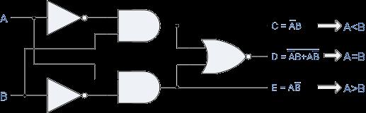
77 A one-bit digital comparator circuit [
78 Truth table for a two-bit digital comparator [
79 A two-bit digital comparator circuit [
80 A four-bit comparator circuit [ Figure 4.22 from the textbook ]
81 Example Problems from Chapter 4
82 Example : SOP vs Decoders Implement the function f(w, w 2, w 3 ) = Σ m(,, 3, 4, 6, 7) by using a 3-to-8 binary decoder and one OR gate.
83 Solution Circuit w 3 w y w 2 w w w 2 y y 2 y 3 y 4 y 5 y 6 En y 7 f(w, w 2, w 3 ) = Σ m(,, 3, 4, 6, 7) [ Figure 4.44 from the textbook ]
84 Notice this swap of variables in the two lists. w 3 w Solution Circuit y w 2 w w w 2 Need to match the least significant with the least significant in both. y y 2 y 3 y 4 y 5 y 6 En y 7 f(w, w 2, w 3 ) = Σ m(,, 3, 4, 6, 7) [ Figure 4.44 from the textbook ]
85 Example 2: Implement an 8-to-3 binary encoder [ Figure 4.45 from the textbook ]
86 Example 2: Implement an 8-to-3 binary encoder y = w + w 3 + w 5 + w 7 y = w 2 + w 3 + w 6 + w 7 y 2 = w 4 + w 5 + w 6 + w 7 [ Figure 4.45 from the textbook ]
87 Circuit for the 8-to-3 binary encoder w 7 w 6 w 5 w 4 w 3 w 2 w w y y y 2 y = w + w 3 + w 5 + w 7 y = w 2 + w 3 + w 6 + w 7 y 2 = w 4 + w 5 + w 6 + w 7
88 Example 3: Implement an 8-to-3 priority encoder
89 Example 3: Implement an 8-to-3 priority encoder x x x x x x x x x x x x x x x x x x x x x x x x x x x x
90 Example 3: Implement an 8-to-3 priority encoder x x x x x x x x x x x x x x x x x x x x x x x x x x x x d d d z
91 Example 3: Implement an 8-to-3 priority encoder x x x x x x x x x x x x x x x x x x x x x x x x x x x x d d d z
92 Example 3: Implement an 8-to-3 priority encoder i = w 7 w 6 w 5 w 4 w 3 w 2 w w i = w 7 w 6 w 5 w 4 w 3 w 2 w i 2 = w 7 w 6 w 5 w 4 w 3 w 2 i 3 = w 7 w 6 w 5 w 4 w 3 i 4 = w 7 w 6 w 5 w 4 i 5 = w 7 w 6 w 5 i 6 = w 7 w 6 i 7 = w 7 z = i +i +i 2 +i 3 +i 4 +i 5 +i 6 +i 7 x x x x x x x x x x x x x x x x x x x x x x x x x x x x d d d z
93 Circuit for the 8-to-3 binary encoder w 7 w 6 w 5 w 4 w 3 w 2 w w y y y 2
94 Circuit for the 8-to-3 priority encoder i 7 i 6 i 5 i 4 i 3 i 2 i i w 7 w 6 w 5 w 4 w 3 w 2 w w y y y 2 z
95 Example 4:Circuit implementation using a multiplexer Implement the function f(w, w 2, w 3, w 4, w 5 ) = w w 2 w 4 w 5 + w w 2 + w w 3 + w w 4 + w 3 w 4 w 5 using a 4-to- multiplexer
96 Some Boolean Algebra Leads To w w 2 w 4 w 5 + w w 2 + w w 3 + w w 4 + w 3 w 4 w 5 w w 4 (w 5 w 2 ) + w 4 (w 3 w 5 ) + w (w 2 + w 3 ) + w w 4 () w w 4 (w 5 w 2 ) + ( w +w )w 4 (w 3 w 5 ) + w ( w 4 +w 4 ) (w 2 + w 3 ) + w w 4 () w w 4 (w 5 w 2 ) + w w 4 (w 3 w 5 ) + w w 4 (w 2 + w 3 ) + w w 4 ( w 3 w 5 + (w 2 +w 3 ) + ) w w 4 (w 5 w 2 ) + w w 4 (w 3 w 5 ) + w w 4 (w 2 + w 3 ) + w w 4 () Note that the split is by w and w 4, not w and w 2
97 Solution Circuit [ Figure 4.46 from the textbook ]
98 Some Final Things from Chapter 4
99 A shifter circuit [ Figure 4.5 from the textbook ]
100 A shifter circuit
101 A shifter circuit
102 A shifter circuit w 3 w 2 w w No shift in this case.
103 A shifter circuit
104 A shifter circuit
105 A shifter circuit w 3 w 2 w Shift to the right by bit
106 A shifter circuit w 3 w 2 w w Shift to the right by bit
107 A barrel shifter circuit [ Figure 4.5 from the textbook ]
108 Questions?
109 THE END
CprE 281: Digital Logic
 CprE 28: Digital Logic Instructor: Alexander Stoytchev http://www.ece.iastate.edu/~alexs/classes/ Decoders and Encoders CprE 28: Digital Logic Iowa State University, Ames, IA Copyright Alexander Stoytchev
CprE 281: Digital Logic
 CprE 28: Digital Logic Instructor: Alexander Stoytchev http://www.ece.iastate.edu/~alexs/classes/ Examples of Solved Problems CprE 28: Digital Logic Iowa State University, Ames, IA Copyright Alexander
CprE 281: Digital Logic
 CprE 281: Digital Logic Instructor: Alexander Stoytchev http://www.ece.iastate.edu/~alexs/classes/ Boolean Algebra CprE 281: Digital Logic Iowa State University, Ames, IA Copyright Alexander Stoytchev
CprE 281: Digital Logic
 CprE 281: Digital Logic Instructor: Alexander Stoytchev http://www.ece.iastate.edu/~alexs/classes/ NAND and NOR Logic Networks CprE 281: Digital Logic Iowa State University, Ames, IA Copyright Alexander
CprE 281: Digital Logic
 CprE 281: Digital Logic Instructor: Alexander Stoytchev http://www.ece.iastate.edu/~alexs/classes/ NAND and NOR Logic Networks CprE 281: Digital Logic Iowa State University, Ames, IA Copyright Alexander
CprE 281: Digital Logic
 CprE 281: Digital Logic Instructor: Alexander Stoytchev http://www.ece.iastate.edu/~alexs/classes/ Signed Numbers CprE 281: Digital Logic Iowa State University, Ames, IA Copyright Alexander Stoytchev Administrative
CprE 281: Digital Logic
 CprE 281: Digital Logic Instructor: Alexander Stoytchev http://www.ece.iastate.edu/~alexs/classes/ Design Examples CprE 281: Digital Logic Iowa State University, Ames, IA Copyright Alexander Stoytchev
CprE 281: Digital Logic
 CprE 281: Digital Logic Instructor: Alexander Stoytchev http://www.ece.iastate.edu/~alexs/classes/ Design Examples CprE 281: Digital Logic Iowa State University, Ames, IA Copyright Alexander Stoytchev
CprE 281: Digital Logic
 CprE 281: Digital Logic Instructor: Alexander Stoytchev http://www.ece.iastate.edu/~alexs/classes/ Fast Adders CprE 281: Digital Logic Iowa State University, Ames, IA Copyright Alexander Stoytchev HW5
CprE 281: Digital Logic
 CprE 281: Digital Logic Instructor: Alexander Stoytchev http://www.ece.iastate.edu/~alexs/classes/ Multiplication CprE 281: Digital Logic Iowa State University, Ames, IA Copyright Alexander Stoytchev HW
ECE 545 Digital System Design with VHDL Lecture 1A. Digital Logic Refresher Part A Combinational Logic Building Blocks
 ECE 545 Digital System Design with VHDL Lecture A Digital Logic Refresher Part A Combinational Logic Building Blocks Lecture Roadmap Combinational Logic Basic Logic Review Basic Gates De Morgan s Laws
Unit 3 Session - 9 Data-Processing Circuits
 Objectives Unit 3 Session - 9 Data-Processing Design of multiplexer circuits Discuss multiplexer applications Realization of higher order multiplexers using lower orders (multiplexer trees) Introduction
CprE 281: Digital Logic
 CprE 28: Digital Logic Instructor: Alexander Stoytchev http://www.ece.iastate.edu/~alexs/classes/ Simple Processor CprE 28: Digital Logic Iowa State University, Ames, IA Copyright Alexander Stoytchev Digital
Digital Logic Design ENEE x. Lecture 14
 Digital Logic Design ENEE 244-010x Lecture 14 Announcements Homework 6 due today Agenda Last time: Binary Adders and Subtracters (5.1, 5.1.1) Carry Lookahead Adders (5.1.2, 5.1.3) This time: Decimal Adders
Combinational Logic. By : Ali Mustafa
 Combinational Logic By : Ali Mustafa Contents Adder Subtractor Multiplier Comparator Decoder Encoder Multiplexer How to Analyze any combinational circuit like this? Analysis Procedure To obtain the output
CprE 281: Digital Logic
 CprE 281: Digital Logic Instructor: Alexander Stoytchev http://www.ece.iastate.edu/~alexs/classes/ Synchronous Sequential Circuits Basic Design Steps CprE 281: Digital Logic Iowa State University, Ames,
CSE 140 Lecture 11 Standard Combinational Modules. CK Cheng and Diba Mirza CSE Dept. UC San Diego
 CSE 4 Lecture Standard Combinational Modules CK Cheng and Diba Mirza CSE Dept. UC San Diego Part III - Standard Combinational Modules (Harris: 2.8, 5) Signal Transport Decoder: Decode address Encoder:
Chapter 3 Combinational Logic Design
 Logic and Computer Design Fundamentals Chapter 3 Combinational Logic Design Part 2 Combinational Logic Charles Kime & Thomas Kaminski 28 Pearson Education, Inc. (Hyperlinks are active in View Show mode)
ECE 341. Lecture # 3
 ECE 341 Lecture # 3 Instructor: Zeshan Chishti zeshan@ece.pdx.edu October 7, 2013 Portland State University Lecture Topics Counters Finite State Machines Decoders Multiplexers Reference: Appendix A of
ECE 545 Digital System Design with VHDL Lecture 1. Digital Logic Refresher Part A Combinational Logic Building Blocks
 ECE 545 Digital System Design with VHDL Lecture Digital Logic Refresher Part A Combinational Logic Building Blocks Lecture Roadmap Combinational Logic Basic Logic Review Basic Gates De Morgan s Law Combinational
ELCT201: DIGITAL LOGIC DESIGN
 ELCT201: DIGITAL LOGIC DESIGN Dr. Eng. Haitham Omran, haitham.omran@guc.edu.eg Dr. Eng. Wassim Alexan, wassim.joseph@guc.edu.eg Lecture 5 Following the slides of Dr. Ahmed H. Madian ذو الحجة 1438 ه Winter
DESIGN AND IMPLEMENTATION OF ENCODERS AND DECODERS. To design and implement encoders and decoders using logic gates.
 DESIGN AND IMPLEMENTATION OF ENCODERS AND DECODERS AIM To design and implement encoders and decoders using logic gates. COMPONENTS REQUIRED S.No Components Specification Quantity 1. Digital IC Trainer
Slides for Lecture 19
 Slides for Lecture 19 ENEL 353: Digital Circuits Fall 2013 Term Steve Norman, PhD, PEng Electrical & Computer Engineering Schulich School of Engineering University of Calgary 23 October, 2013 ENEL 353
MODULAR CIRCUITS CHAPTER 7
 CHAPTER 7 MODULAR CIRCUITS A modular circuit is a digital circuit that performs a specific function or has certain usage. The modular circuits to be introduced in this chapter are decoders, encoders, multiplexers,
COSC 243. Introduction to Logic And Combinatorial Logic. Lecture 4 - Introduction to Logic and Combinatorial Logic. COSC 243 (Computer Architecture)
") COSC 243 Introduction to Logic And Combinatorial Logic 1 Overview This Lecture Introduction to Digital Logic Gates Boolean algebra Combinatorial Logic Source: Chapter 11 (10 th edition) Source: J.R. Gregg,
COSC 243 Introduction to Logic And Combinatorial Logic 1 Overview This Lecture Introduction to Digital Logic Gates Boolean algebra Combinatorial Logic Source: Chapter 11 (10 th edition) Source: J.R. Gregg,
Z = F(X) Combinational circuit. A combinational circuit can be specified either by a truth table. Truth Table
 Combinational circuit. A combinational circuit can be specified either by a truth table. Truth Table") Lesson Objectives In this lesson, you will learn about What are combinational circuits Design procedure of combinational circuits Examples of combinational circuit design Combinational Circuits Logic circuit
Lesson Objectives In this lesson, you will learn about What are combinational circuits Design procedure of combinational circuits Examples of combinational circuit design Combinational Circuits Logic circuit
Logic. Combinational. inputs. outputs. the result. system can
 Digital Electronics Combinational Logic Functions Digital logic circuits can be classified as either combinational or sequential circuits. A combinational circuit is one where the output at any time depends
Combinational Logic Design Combinational Functions and Circuits
 Combinational Logic Design Combinational Functions and Circuits Overview Combinational Circuits Design Procedure Generic Example Example with don t cares: BCD-to-SevenSegment converter Binary Decoders
3. Combinational Circuit Design
 CSEE 3827: Fundamentals of Computer Systems, Spring 2 3. Combinational Circuit Design Prof. Martha Kim (martha@cs.columbia.edu) Web: http://www.cs.columbia.edu/~martha/courses/3827/sp/ Outline (H&H 2.8,
Function of Combinational Logic ENT263
 Function of Combinational Logic ENT263 Chapter Objectives Distinguish between half-adder and full-adder Use BCD-to-7-segment decoders in display systems Apply multiplexer in data selection Use decoders
Floating Point Representation and Digital Logic. Lecture 11 CS301
 Floating Point Representation and Digital Logic Lecture 11 CS301 Administrative Daily Review of today s lecture w Due tomorrow (10/4) at 8am Lab #3 due Friday (9/7) 1:29pm HW #5 assigned w Due Monday 10/8
XOR - XNOR Gates. The graphic symbol and truth table of XOR gate is shown in the figure.
 XOR - XNOR Gates Lesson Objectives: In addition to AND, OR, NOT, NAND and NOR gates, exclusive-or (XOR) and exclusive-nor (XNOR) gates are also used in the design of digital circuits. These have special
Logic Design Combinational Circuits. Digital Computer Design
 Logic Design Combinational Circuits Digital Computer Design Topics Combinational Logic Karnaugh Maps Combinational uilding locks Timing 2 Logic Circuit logic circuit is composed of: Inputs Outputs Functional
CSEE 3827: Fundamentals of Computer Systems. Combinational Circuits
 CSEE 3827: Fundamentals of Computer Systems Combinational Circuits Outline (M&K 3., 3.3, 3.6-3.9, 4.-4.2, 4.5, 9.4) Combinational Circuit Design Standard combinational circuits enabler decoder encoder
Chapter 3 Ctd: Combinational Functions and Circuits
 Chapter 3 Ctd: Combinational Functions and Circuits 1 Value Fixing, Transferring, and Inverting Four different functions are possible as a function of single Boolean variable Transferring Inverting Value
ECE 2300 Digital Logic & Computer Organization
 ECE 23 Digital Logic & Computer Organization Spring 28 Combinational Building Blocks Lecture 5: Announcements Lab 2 prelab due tomorrow HW due Friday HW 2 to be posted on Thursday Lecture 4 to be replayed
211: Computer Architecture Summer 2016
 211: Computer Architecture Summer 2016 Liu Liu Topic: Storage Project3 Digital Logic - Storage: Recap - Review: cache hit rate - Project3 - Digital Logic: - truth table => SOP - simplification: Boolean
Chapter 4. Combinational: Circuits with logic gates whose outputs depend on the present combination of the inputs. elements. Dr.
 Chapter 4 Dr. Panos Nasiopoulos Combinational: Circuits with logic gates whose outputs depend on the present combination of the inputs. Sequential: In addition, they include storage elements Combinational
Slides for Lecture 16
 Slides for Lecture 6 ENEL 353: Digital Circuits Fall 203 Term Steve Norman, PhD, PEng Electrical & Computer Engineering Schulich School of Engineering University of Calgary 6 October, 203 ENEL 353 F3 Section
Digital Logic: Boolean Algebra and Gates. Textbook Chapter 3
 Digital Logic: Boolean Algebra and Gates Textbook Chapter 3 Basic Logic Gates XOR CMPE12 Summer 2009 02-2 Truth Table The most basic representation of a logic function Lists the output for all possible
Number System. Decimal to binary Binary to Decimal Binary to octal Binary to hexadecimal Hexadecimal to binary Octal to binary
 Number System Decimal to binary Binary to Decimal Binary to octal Binary to hexadecimal Hexadecimal to binary Octal to binary BOOLEAN ALGEBRA BOOLEAN LOGIC OPERATIONS Logical AND Logical OR Logical COMPLEMENTATION
CMSC 313 Lecture 19 Combinational Logic Components Programmable Logic Arrays Karnaugh Maps
 CMSC 33 Lecture 9 Combinational Logic Components Programmable Logic rrays Karnaugh Maps UMC, CMSC33, Richard Chang Last Time & efore Returned midterm exam Half adders & full adders Ripple
CPE100: Digital Logic Design I
 Professor Brendan Morris, SEB 3216, brendan.morris@unlv.edu CPE100: Digital Logic Design I Midterm02 Review http://www.ee.unlv.edu/~b1morris/cpe100/ 2 Logistics Thursday Nov. 16 th In normal lecture (13:00-14:15)
Part 1: Digital Logic and Gates. Analog vs. Digital waveforms. The digital advantage. In real life...
 Part 1: Digital Logic and Gates Analog vs Digital waveforms An analog signal assumes a continuous range of values: v(t) ANALOG A digital signal assumes discrete (isolated, separate) values Usually there
Boolean Algebra & Digital Logic
 Boolean Algebra & Digital Logic Boolean algebra was developed by the Englishman George Boole, who published the basic principles in the 1854 treatise An Investigation of the Laws of Thought on Which to
CS1800 Discrete Structures Fall 2017 October, CS1800 Discrete Structures Midterm Version A
 CS1800 Discrete Structures Fall 2017 October, 2017 CS1800 Discrete Structures Midterm Version A Instructions: 1. The exam is closed book and closed notes. You may not use a calculator or any other electronic
COMBINATIONAL LOGIC FUNCTIONS
 COMBINATIONAL LOGIC FUNCTIONS Digital logic circuits can be classified as either combinational or sequential circuits. A combinational circuit is one where the output at any time depends only on the present
CHAPTER VI COMBINATIONAL LOGIC BUILDING BLOCKS
 CHAPTR VI- CHAPTR VI CHAPTR VI BUILDING BLOCKS R.M. Dansereau; v.. CHAPTR VI- COMBINAT. LOGIC INTRODUCTION -INTRODUCTION Combinational logic Output at any time is determined completely by the current input.
Lecture 2 Review on Digital Logic (Part 1)
") Lecture 2 Review on Digital Logic (Part 1) Xuan Silvia Zhang Washington University in St. Louis http://classes.engineering.wustl.edu/ese461/ Grading Engagement 5% Review Quiz 10% Homework 10% Labs 40%
Lecture 2 Review on Digital Logic (Part 1) Xuan Silvia Zhang Washington University in St. Louis http://classes.engineering.wustl.edu/ese461/ Grading Engagement 5% Review Quiz 10% Homework 10% Labs 40%
CHAPTER1: Digital Logic Circuits Combination Circuits
 CS224: Computer Organization S.KHABET CHAPTER1: Digital Logic Circuits Combination Circuits 1 PRIMITIVE LOGIC GATES Each of our basic operations can be implemented in hardware using a primitive logic gate.
Fundamentals of Digital Design
 Fundamentals of Digital Design Digital Radiation Measurement and Spectroscopy NE/RHP 537 1 Binary Number System The binary numeral system, or base-2 number system, is a numeral system that represents numeric
Systems I: Computer Organization and Architecture
 Systems I: Computer Organization and Architecture Lecture 6 - Combinational Logic Introduction A combinational circuit consists of input variables, logic gates, and output variables. The logic gates accept
Computer Science Final Examination Friday December 14 th 2001
 Computer Science 03 60 265 Final Examination Friday December 14 th 2001 Dr. Robert D. Kent and Dr. Alioune Ngom Last Name: First Name: Student Number: INSTRUCTIONS EXAM DURATION IS 3 HOURs. CALCULATORS,
Introduction to Computer Engineering ECE 203
 Introduction to Computer Engineering ECE 203 Northwestern University Department of Electrical Engineering and Computer Science Teacher: Robert Dick Office: L477 Tech Email: dickrp@ece.northwestern.edu
Digital Logic. CS211 Computer Architecture. l Topics. l Transistors (Design & Types) l Logic Gates. l Combinational Circuits.
 l Logic Gates. l Combinational Circuits.") CS211 Computer Architecture Digital Logic l Topics l Transistors (Design & Types) l Logic Gates l Combinational Circuits l K-Maps Figures & Tables borrowed from:! http://www.allaboutcircuits.com/vol_4/index.html!
CS211 Computer Architecture Digital Logic l Topics l Transistors (Design & Types) l Logic Gates l Combinational Circuits l K-Maps Figures & Tables borrowed from:! http://www.allaboutcircuits.com/vol_4/index.html!
CprE 281: Digital Logic
 CprE 281: igital Logic Instructor: Alexander Stoytchev http://www.ece.iastate.edu/~alexs/classes/ State Minimization CprE 281: igital Logic Iowa State University, Ames, IA Copyright Alexander Stoytchev
Chapter 4: Combinational Logic Solutions to Problems: [1, 5, 9, 12, 19, 23, 30, 33]
![Chapter 4: Combinational Logic Solutions to Problems: [1, 5, 9, 12, 19, 23, 30, 33]](/thumbs/81/84077758.jpg "Chapter 4: Combinational Logic Solutions to Problems: [1, 5, 9, 12, 19, 23, 30, 33]") Chapter 4: Combinational Logic Solutions to Problems: [, 5, 9, 2, 9, 23, 3, 33] Problem: 4- Consider the combinational circuit shown in Fig. P4-. (a) Derive the Boolean expressions for T through T 4. Evaluate
Chapter 4: Combinational Logic Solutions to Problems: [, 5, 9, 2, 9, 23, 3, 33] Problem: 4- Consider the combinational circuit shown in Fig. P4-. (a) Derive the Boolean expressions for T through T 4. Evaluate
Total Time = 90 Minutes, Total Marks = 50. Total /50 /10 /18
 University of Waterloo Department of Electrical & Computer Engineering E&CE 223 Digital Circuits and Systems Midterm Examination Instructor: M. Sachdev October 23rd, 2007 Total Time = 90 Minutes, Total
Computer Science 324 Computer Architecture Mount Holyoke College Fall Topic Notes: Digital Logic
 Computer Science 324 Computer Architecture Mount Holyoke College Fall 2007 Topic Notes: Digital Logic Our goal for the next few weeks is to paint a a reasonably complete picture of how we can go from transistor
Boolean Algebra, Gates and Circuits
 Boolean Algebra, Gates and Circuits Kasper Brink November 21, 2017 (Images taken from Tanenbaum, Structured Computer Organization, Fifth Edition, (c) 2006 Pearson Education, Inc.) Outline Last week: Von
Binary addition example worked out
 Binary addition example worked out Some terms are given here Exercise: what are these numbers equivalent to in decimal? The initial carry in is implicitly 0 1 1 1 0 (Carries) 1 0 1 1 (Augend) + 1 1 1 0
Numbers and Arithmetic
 Numbers and Arithmetic See: P&H Chapter 2.4 2.6, 3.2, C.5 C.6 Hakim Weatherspoon CS 3410, Spring 2013 Computer Science Cornell University Big Picture: Building a Processor memory inst register file alu
CS 226: Digital Logic Design
 CS 226: Digital Logic Design 0 1 1 I S 0 1 0 S Department of Computer Science and Engineering, Indian Institute of Technology Bombay. 1 of 29 Objectives In this lecture we will introduce: 1. Logic functions
COMBINATIONAL LOGIC CIRCUITS. Dr. Mudathir A. Fagiri
 COMBINATIONAL LOGIC CIRCUITS Dr. Mudathir A. Fagiri Standard Combinational Modules Decoder: Decode address Encoder: Encode address Multiplexer (Mux): Select data by address Demultiplexier (DeMux): Direct
Numbers and Arithmetic
 Numbers and Arithmetic See: P&H Chapter 2.4 2.6, 3.2, C.5 C.6 Hakim Weatherspoon CS 3410, Spring 2013 Computer Science Cornell University Big Picture: Building a Processor memory inst register file alu
CMSC 313 Lecture 18 Midterm Exam returned Assign Homework 3 Circuits for Addition Digital Logic Components Programmable Logic Arrays
 CMSC 33 Lecture 8 Midterm Exam returned ssign Homework 3 Circuits for ddition Digital Logic Components Programmable Logic rrays UMC, CMSC33, Richard Chang Half dder Inputs: and Outputs:
COSC3330 Computer Architecture Lecture 2. Combinational Logic
 COSC333 Computer rchitecture Lecture 2. Combinational Logic Instructor: Weidong Shi (Larry), PhD Computer Science Department University of Houston Today Combinational Logic oolean lgebra Mux, DeMux, Decoder
Chapter 3 Combinational Logic Design
 Logic and Computer Design Fundamentals Chapter 3 Combinational Logic Design Part 1- Implementation Technology and Logic Design Overview Part 1-Implementation Technology and Logic Design Design Concepts
XI STANDARD [ COMPUTER SCIENCE ] 5 MARKS STUDY MATERIAL.
![XI STANDARD [ COMPUTER SCIENCE ] 5 MARKS STUDY MATERIAL.](/thumbs/81/84726747.jpg "XI STANDARD [ COMPUTER SCIENCE ] 5 MARKS STUDY MATERIAL.") 2017-18 XI STANDARD [ COMPUTER SCIENCE ] 5 MARKS STUDY MATERIAL HALF ADDER 1. The circuit that performs addition within the Arithmetic and Logic Unit of the CPU are called adders. 2. A unit that adds two
2017-18 XI STANDARD [ COMPUTER SCIENCE ] 5 MARKS STUDY MATERIAL HALF ADDER 1. The circuit that performs addition within the Arithmetic and Logic Unit of the CPU are called adders. 2. A unit that adds two
Hardware Design I Chap. 4 Representative combinational logic
 Hardware Design I Chap. 4 Representative combinational logic E-mail: shimada@is.naist.jp Already optimized circuits There are many optimized circuits which are well used You can reduce your design workload
We are here. Assembly Language. Processors Arithmetic Logic Units. Finite State Machines. Circuits Gates. Transistors
 CSC258 Week 3 1 Logistics If you cannot login to MarkUs, email me your UTORID and name. Check lab marks on MarkUs, if it s recorded wrong, contact Larry within a week after the lab. Quiz 1 average: 86%
Logic Design I (17.341) Fall Lecture Outline
 Fall Lecture Outline") Logic Design I (17.341) Fall 2011 Lecture Outline Class # 06 October 24, 2011 Dohn Bowden 1 Today s Lecture Administrative Main Logic Topic Homework 2 Course Admin 3 Administrative Admin for tonight Syllabus
Logic Design I (17.341) Fall 2011 Lecture Outline Class # 06 October 24, 2011 Dohn Bowden 1 Today s Lecture Administrative Main Logic Topic Homework 2 Course Admin 3 Administrative Admin for tonight Syllabus
A B OUT_0 OUT_1 OUT_2 OUT_
 A B OUT_0 OUT_1 OUT_2 OUT_3 0 0 1 0 0 0 0 1 0 1 0 0 1 0 0 0 1 0 1 1 0 0 0 1 A Decoder is something that does the opposite of encoding; it converts the data back into its original form. This decoder converts
CSC9R6 Computer Design. Practical Digital Logic
 CSC9R6 Computer Design Practical Digital Logic 1 References (for this part of CSC9R6) Hamacher et al: Computer Organization App A. In library Floyd: Digital Fundamentals Ch 1, 3-6, 8-10 web page: www.prenhall.com/floyd/
Boolean Logic Continued Prof. James L. Frankel Harvard University
 Boolean Logic Continued Prof. James L. Frankel Harvard University Version of 10:18 PM 5-Sep-2017 Copyright 2017, 2016 James L. Frankel. All rights reserved. D Latch D R S Clk D Clk R S X 0 ~S 0 = R 0 ~R
CS1800 Discrete Structures Final Version A
 CS1800 Discrete Structures Fall 2017 Profs. Aslam, Gold, & Pavlu December 11, 2017 CS1800 Discrete Structures Final Version A Instructions: 1. The exam is closed book and closed notes. You may not use
ENGIN 112 Intro to Electrical and Computer Engineering
 ENGIN 112 Intro to Electrical and Computer Engineering Lecture 17 Encoders and Decoders Overview Binary decoders Converts an n-bit code to a single active output Can be developed using AND/OR gates Can
Chapter 2 Combinational Logic Circuits
 Logic and Computer Design Fundamentals Chapter 2 Combinational Logic Circuits Part 3 Additional Gates and Circuits Charles Kime & Thomas Kaminski 2008 Pearson Education, Inc. (Hyperlinks are active in
Combinatorial RTL Components
 Principles Of Digital Design Combinatorial RTL Components Computation and Reorganization Arithmetic and Comparison Components Logic Components election Components ncoding/decoding Components Bit manipulation
Combinational Logic Design/Circuits
 3 ` Combinational Logic Design/Circuits Chapter-3(Hours : 12 Marks:24 ) Combinational Logic design / Circuits 3.1 Simplification of Boolean expression using Boolean algebra. 3.2 Construction of logical
Software Engineering 2DA4. Slides 8: Multiplexors and More
 Software Engineering 2DA4 Slides 8: Multiplexors and More Dr. Ryan Leduc Department of Computing and Software McMaster University Material based on S. Brown and Z. Vranesic, Fundamentals of Digital Logic
CHAPTER VI COMBINATIONAL LOGIC BUILDING BLOCKS
 CHAPTR VI- CHAPTR VI CHAPTR VI BUILDING BLOCKS R.M. Dansereau; v.. CHAPTR VI- COMBINAT. LOGIC INTRODUCTION -INTRODUCTION Combinational logic Output at any time is determined completely by the current input.
Design of Sequential Circuits
 Design of Sequential Circuits Seven Steps: Construct a state diagram (showing contents of flip flop and inputs with next state) Assign letter variables to each flip flop and each input and output variable
Philadelphia University Student Name: Student Number:
 Philadelphia University Student Name: Student Number: Faculty of Engineering Serial Number: Final Exam, Second Semester: 2015/2016 Dept. of Computer Engineering Course Title: Logic Circuits Date: 08/06/2016
Introduction to Karnaugh Maps
 Introduction to Karnaugh Maps Review So far, you (the students) have been introduced to truth tables, and how to derive a Boolean circuit from them. We will do an example. Consider the truth table for
UNIVERSITY OF WISCONSIN MADISON
 CS/ECE 252: INTRODUCTION TO COMPUTER ENGINEERING UNIVERSITY OF WISCONSIN MADISON Prof. Gurindar Sohi TAs: Minsub Shin, Lisa Ossian, Sujith Surendran Midterm Examination 2 In Class (50 minutes) Friday,
Combinational Logic. Mantıksal Tasarım BBM231. section instructor: Ufuk Çelikcan
 Combinational Logic Mantıksal Tasarım BBM23 section instructor: Ufuk Çelikcan Classification. Combinational no memory outputs depends on only the present inputs expressed by Boolean functions 2. Sequential
Class Website:
 ECE 20B, Winter 2003 Introduction to Electrical Engineering, II LECTURE NOTES #5 Instructor: Andrew B. Kahng (lecture) Email: abk@ece.ucsd.edu Telephone: 858-822-4884 office, 858-353-0550 cell Office:
Answers. Name: Grade: Q1 Q2 Q3 Q4 Total mean: 83, stdev: 14. ESE370 Fall 2017
 University of Pennsylvania Department of Electrical and System Engineering Circuit-Level Modeling, Design, and Optimization for Digital Systems ESE370, Fall 2017 Midterm 2 Monday, November 6 Point values
Slides for Lecture 10
 Slides for Lecture 10 ENEL 353: Digital Circuits Fall 2013 Term Steve Norman, PhD, PEng Electrical & Computer Engineering Schulich School of Engineering University of Calgary 30 September, 2013 ENEL 353
Computer Science. 19. Combinational Circuits. Computer Science COMPUTER SCIENCE. Section 6.1.
 COMPUTER SCIENCE S E D G E W I C K / W A Y N E PA R T I I : A L G O R I T H M S, M A C H I N E S, a n d T H E O R Y Computer Science Computer Science An Interdisciplinary Approach Section 6.1 ROBERT SEDGEWICK
Arithmetic Circuits-2
 Arithmetic Circuits-2 Multipliers Array multipliers Shifters Barrel shifter Logarithmic shifter ECE 261 Krish Chakrabarty 1 Binary Multiplication M-1 X = X i 2 i i=0 Multiplicand N-1 Y = Y i 2 i i=0 Multiplier
2009 Spring CS211 Digital Systems & Lab CHAPTER 2: INTRODUCTION TO LOGIC CIRCUITS
 CHAPTER 2: INTRODUCTION TO LOGIC CIRCUITS What will we learn? 2 Logic functions and circuits Boolean Algebra Logic gates and Synthesis CAD tools and VHDL Read Section 2.9 and 2.0 Terminology 3 Digital
1 Boolean Algebra Simplification
 cs281: Computer Organization Lab3 Prelab Our objective in this prelab is to lay the groundwork for simplifying boolean expressions in order to minimize the complexity of the resultant digital logic circuit.
Sample Test Paper - I
 Scheme G Sample Test Paper - I Course Name : Computer Engineering Group Marks : 25 Hours: 1 Hrs. Q.1) Attempt any THREE: 09 Marks a) Define i) Propagation delay ii) Fan-in iii) Fan-out b) Convert the following:
1.10 (a) Function of AND, OR, NOT, NAND & NOR Logic gates and their input/output.
 Function of AND, OR, NOT, NAND & NOR Logic gates and their input/output.") Chapter 1.10 Logic Gates 1.10 (a) Function of AND, OR, NOT, NAND & NOR Logic gates and their input/output. Microprocessors are the central hardware that runs computers. There are several components that
Chapter 1.10 Logic Gates 1.10 (a) Function of AND, OR, NOT, NAND & NOR Logic gates and their input/output. Microprocessors are the central hardware that runs computers. There are several components that
Overview. Multiplexor. cs281: Introduction to Computer Systems Lab02 Basic Combinational Circuits: The Mux and the Adder
 cs281: Introduction to Computer Systems Lab02 Basic Combinational Circuits: The Mux and the Adder Overview The objective of this lab is to understand two basic combinational circuits the multiplexor and
Boolean Algebra and Digital Logic 2009, University of Colombo School of Computing
 IT 204 Section 3.0 Boolean Algebra and Digital Logic Boolean Algebra 2 Logic Equations to Truth Tables X = A. B + A. B + AB A B X 0 0 0 0 3 Sum of Products The OR operation performed on the products of
Slide Set 6. for ENEL 353 Fall Steve Norman, PhD, PEng. Electrical & Computer Engineering Schulich School of Engineering University of Calgary
 Slide Set 6 for ENEL 353 Fall 2017 Steve Norman, PhD, PEng Electrical & Computer Engineering Schulich School of Engineering University of Calgary Fall Term, 2017 SN s ENEL 353 Fall 2017 Slide Set 6 slide
Lecture 1: Shannon s Theorem
 Lecture 1: Shannon s Theorem Lecturer: Travis Gagie January 13th, 2015 Welcome to Data Compression! I m Travis and I ll be your instructor this week. If you haven t registered yet, don t worry, we ll work