rock mass structure characteristics accurate and precise
|
|
|
- Polly Hancock
- 5 years ago
- Views:
Transcription
1

2 Introduction Geotechnical data provides information on rock mass and structure characteristics which will be relied upon for slope and underground design at the Back River deposits. It is important that the data collected be accurate and precise, so that SRK can assist to design a safe, but cost effective mine plan for Back River.
3 ROCK MASS RATING FIELD GEOTECH DATA PARAMETERS CALCULATION GEOTECHNICAL DESIGN STARTS WITH PROPER DATA COLLECTION STRUCTURAL ANALYSIS FIELD STRUCT. DATA PARAMETERS CALCULATION DATABASE GEOMETRY (3D MODEL) STRUCTURAL ANALYSIS STABILITY ANALYSIS & DESIGN
4 INTACT ROCK STRENGTH FRACTURE FREQUENCY (Fractures per meter) JOINT CONDITIONS IN-SITU PARAMETERS LAUBSCHER S RMR CLASSIFICATION SYSTEM ROCK MASS RATING - RMR (0-100) ROCK MASS STRENGTH - RMS (MPa) RMR (ROCK MASS RATING) WEATHERING ORIENTATION INDUCED STRESS BLASTING MINING ADJUSTMENTS IRS (20 %) MINING ROCK MASS RATING - MRMR (0-100) DESIGN ROCK MASS STRENGTH - DRMS (MPa)
5 Contents A) Identifying fractures 1) Fracture types: Joints, mechanical breaks, cemented joints, core handling breaks B) Basic logging 1) Runs C) Detailed logging 2) Core marking 3) Rubble Zones 2) TCR 3) RQD 1) Open fracture count, joint count etc. 2) Intact Rock Strength 3) Micro Defects 4) Describing joints 5) Joint sets 6) Major structures D) Oriented Core logging 1) Core orientation 2) Alpha and Beta angles
6 A) Identifying Fractures
 core pieces and exhibit no tensile strength.")
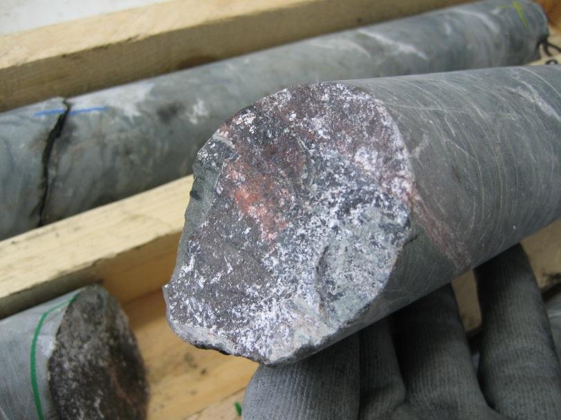
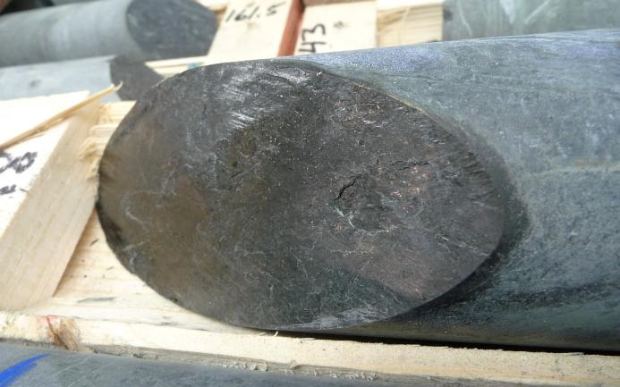
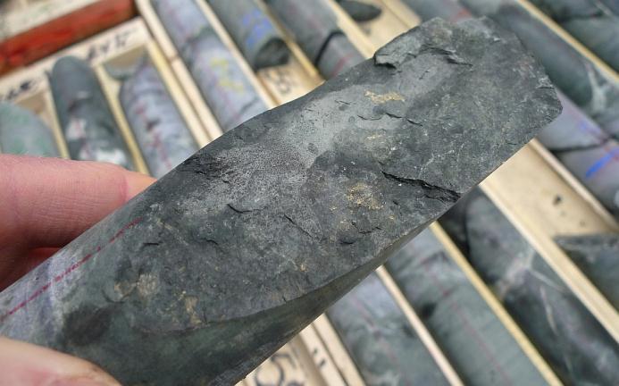
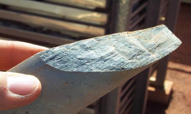
7 Joints In the core, indications of a naturally occurring, insitu joint include: Freshness Joints often are not fresh. Staining Joints are often stained or have some type of coating or fill. No tensile strength Joints separate solid (intact) core pieces and exhibit no tensile strength. Roughness of break The edges of a joint usually do not match back together as seamlessly as a mechanical break. Angle of break Low angle breaks are more likely to be joints than mechanical breaks.

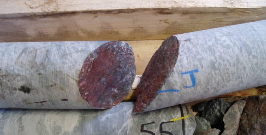
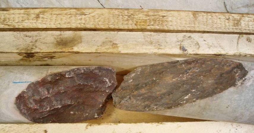
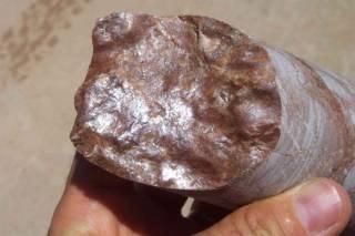
8 Examples of Joints

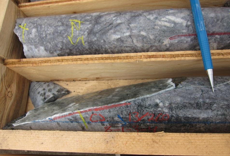
9 Mechanical Breaks Mechanical breaks are artificial breaks in the core that have been created by the drilling process (i.e. fresh breaks). Indications of a mechanical break include: Freshness fresh looking surface could indicate artificial break Angle of break break perpendicular to the core axis could be an indication of an artificial break Roughness rough surface could indicate artificial break Coating - no coating or fill could indicate artificial break Spin marks from the drill. Mechanical breaks are often found near the end of the drilling run, or near the end of the box row, where the driller s helper has hit the core to fit it in the box. If you are really unsure if something is a joint or a mechanical break, you should err on the side of caution and call it a joint.


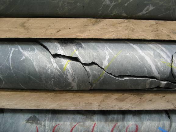
10 Examples of Mechanical Breaks Note high angle, very fresh break indicating drill damage. Cluster of foliation sub-parallel fractures roughness and angularity indicate mechanical damage. Although sub-parallel to foliation, roughness and angularity of break indicate mechanical damage. Drill spin is an obvious indication of mechanical damage.
 are marked with a yellow line ( ) across the break.")
11 J Core Marking J J X X Four sources of fractures can be found in the drill core, and are marked as follows: Artificial breaks induced by the core handling process should be marked with a yellow (X). Artificial breaks induced by the drilling process (mechanical breaks) are marked with a yellow line ( ) across the break. Natural joints that are present in the rock mass are marked with a red (J) and a line along the joint. Microdefects are noted on the core with in blue (MD) Write down all parameters and physically comment on core where possible. X J J X

12 Rubble Zones Rubble zones are sections of core that are broken, very jointed, sheared, or filled with gouge. Rubble zones may be a associated with tightly spaced joints, highly altered or weak ground or fault zones. Rubble zones are either: Natural Rubble Zones (RZ), which are created by a fault or series of joints in close succession; or Mechanical Rubble Zones (MRZ), which are created artificially by the drilling process, and are essentially a series of mechanical breaks in close succession. Natural Rubble Zones often have staining or fill, and look weathered. Mechanical Rubble Zones are often jagged and fresh looking, with no staining or fill. If you are unsure whether a rubble zone is natural or mechanical, classify as a natural rubble zone.


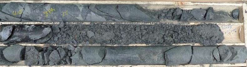
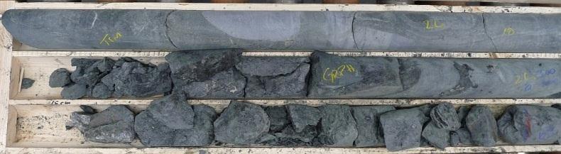
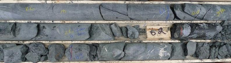
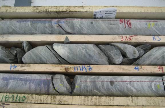
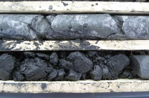
13 Examples of Rubble Zones RZ RZ RZ
14 Rubble Zones How to Allocate Fractures? It is not possible to actually count the joints natural rubble zones, therefore we log the rubble zones as follows: Natural Rubble Zones (RZ) are assumed to have 4 joints per 10cm of rubble zone. Mechanical Rubble Zones (MRZ) are noted on the core but not counted. Often rubble zones are interspersed with short sections of competent core, or competent core with a few joints. If the competent sections between the rubble are less than approximately 30cm long, mark it as one rubble zone. For natural rubble zones, ensure to include the interval in the major structures log. Place all allocated joints in JOINT SET 1 (discussed later). You should use your judgment to determine an appropriate joint count for these rubble zones i.e. do not apply the 4J/10cm rule across sections of competent rock between rubble - see example on next page.
15 Example of how to count 0cm 20cm 40cm 60cm 80cm 100cm 120cm 140cm 150cm RZ J J RZ 25cm = 10 J 20cm = 8 J Total joints in the above section = = 20 joints for the run RZ The above rubble zone is 110cm long, but the actual rubble makes up 25cm + 24cm + 21cm = 70cm, so we use our judgement in applying the 4J/10cm rule, and give the rubble zone 28 joints for the run.
. Natural Rubble Zones are taken out of RQD measurements (discussed later).")
16 Rubble Zones Summary Natural Rubble Zone (RZ) Include all Natural Rubble Zones as well as those you are unsure of. 4 counts are added to the open fractures count and the joint count (discussed later). Natural Rubble Zones must be marked in the Major Structures Tab (discussed later). Natural Rubble Zones are taken out of RQD measurements (discussed later). Mechanical Rubble Zone (MRZ) Mechanical Rubble Zones are induced by the drilling process. Consider a rubble zone mechanical only if you are 100% sure it was caused by drilling! Nothing is added to the joint count. Mechanical rubble zones are not marked in the Major Structures Tab or taken out of RQD measurements.
17 B) Basic Logging

18 Runs Basic logging is conducted for every run. The drilling run is considered to be the length of rod that was drilled into the ground before recovering the core inner-tube. At the end of every drilling run, the driller brings the core innertube to the surface to empty. A full drilling run should be 3.0m±10%. The driller s helper will mark the end of each run by putting a wooden block in the core box, indicating the depth of the run end.
19 Total Core Recovery Total Core Recovery (TCR) is the sum of all measurable core recovered in one drill run. TCR is measured for each run length drilled. To measure TCR: Fit the core together as best as possible; For the broken zones, push the broken pieces together so that it approximately resembles a core volume; Measure the total length of core recovered, including the solid and broken zones. The actual distance of the run is also recorded, and is obtained from the driller, using the rod measurements. The TCR ratio (the ratio of core recovered to run length) is very important in the weaker rock types, where core loss can be expected (mainly fault zones at Back River).
20 Total Core Recovery Example B ROCK TYPE 1 ROCK TYPE 2 In the example above, Run B (highlighted B in yellow) is indicated by the drillers block marks to be 3m long. To calculate the TCR, you would measure the actual core recovered, by measuring where the orange arrows indicate. The TCR of interval B is approximately 2.4m, while the indicated drill run is 3.0m. If core is lost and fault zones are present, assume the missing material is both the weakest and most fractured of what is observed in the run and enter this allocated strength in the database.
21 Rock Quality Designation Rock Quality Designation (RQD) is an indication of how jointed and weak the rock is, measured as the total length of core pieces that are longer than 10cm. To determine RQD for each run, you should measure the length of core recovered, EXCLUDING: Sections where there are joints closer than 10cm together Natural rubble zones Soft core, with a strength rating of R0 or R1 (discussed later) Notes: Machine breaks and core handling breaks should be considered solid core, i.e. they are included in the RQD measurement Joints along the core axis should be considered solid core, i.e. included in the RQD measurement.
22 RQD example B ROCK TYPE 1 J J J ROCK TYPE 2 B The RQD of interval B in the example is approximately 1.5m (1.5 / 3.0 x 100 = 50%). Areas not counted are circled. Areas that are measured are indicated with orange arrows.

23 RQD example In the example provided above, the yellow boxes are zones removed from RQD while the red circles are not (as they are bounded by mechanical breaks which do not affect RQD).
24 C) Detailed Logging
25 Example of Domain Change ROCK TYPE 1 // D (967.00m) B Remember: Domain changes correspond to changes in structure, intact rock strength (IRS), lithology and alteration. Change in domain at m ROCK TYPE 2 B SAMPLE DRILL RUN: B = m ROCK TYPE 1: Gabbro, Intact Rock Strength =R3, rubble zones ROCK TYPE 2: Pillow basalt, Intact Rock Strength =R5, increased joints and cemented joints, solid core. The changes in geotechnical qualities of run B are significant enough that the run must be split into two separate domains. The resulting changes will be reflected in the Detailed Geotech Form by defining a new domain. The General Geotech Form will also have the new domain change i.e. RQD and TCR are assessed for each domain. NOTE: Realistically, the need for a domain change at Back River will likely be limited to major structures (fault zones) greater than 50cm in length. Otherwise, run-based intervals are usually short enough in length to achieve the required resolution.
26 Fracture Counts Per Run The following items are counted during core logging: Joints: a total count of all joints in the domain. Foliation breaks: a total count of all open breaks along foliation. The count for each run is written on the core in that order: J/FOL Natural rubble zone (RZ) allocated joints are added to the joints count (assuming ~4 joints/10cm). Breaks caused by someone hitting the core with a hammer, i.e. core that is purposely broken to fit it into the core boxes, or to test strength are not included in any counts.
27 Intact Rock Strength As part of the detailed geotechnical log, you need to rate the intact rock strength (IRS). Tests are conducted several times per run, or whenever a difference in rock strength is suspected. In broken rock, you are evaluating the strength of the individual pieces.

28 Intact Rock Strength (IRS) o o o We are estimating rock strength using a rock hammer. A good test will break through intact rock. If the rock breaks along a cemented feature, vein, or microdefect this is not testing the intact rock strength. For broken rock estimate the strength of the rock pieces. Up to two values for IRS are given for each run. The strong rock strength, and the weak rock strength values are entered, as well as a percentage weak to indicate how much of the rock is represented by the weak rock strength value. o In the example above, 80% of the rock is rated as R0, and 20% is rated as R3, and this is entered like this: IRS Strong Weak % Weak R3 R0 80

29 Intact Rock Strength Technique to test core strength with a rock hammer 2 If you have weak rock in your domain, rated as R0 or R1, you also need to further classify it s characteristics in the comments section. Use the table above to further describe the weak rock as S1 S6.
 for each")


 HEAVY (weak) MODERATE (Strong) MINOR")
30 INTENSITY STRENGTH Microdefects As part of the detailed log, you need to rate the strength of microdefects (MD) for each run (if present) The strength of these features can be determined by gently hitting the feature with a rock hammer. STRENGTH OF FILL (Drop Test) MICRODEFECTS - QUANTITY CODE DESCRIPTION 0 NONE 1 MINOR 2 MODERATE 3 HEAVY Code Category 0 Strong (Never breaks) 1 Moderate ( Sometimes breaks) 2 Weak (Always breaks) HEAVY (weak) MODERATE (Strong) MINOR (Strong) NONE
31 Joint Roughness To describe the conditions of the joint, we rate the roughness, alteration of joint walls, and infill. The roughness is evaluated on a scale of 1 to 9 by using the chart on the right (the lines on the chart are 10cm long at full scale).


32 Joint Roughness Examples STEPPED SLICKENSIDED STEPPED ROUGH UNDULATING ROUGH UNDULATING SLICKENSIDED SLICKENED PLANAR SLICKENSIDED PLANAR ROUGH


33 Joint Wall Alteration Joint wall alteration results from fluids moving along the joint and altering the surrounding rock composition. Alteration of the rock on either side of the joint is evaluated as follows: 1 = The altered joint wall is the same strength as the rock around the joint. 2 = The altered joint wall is now stronger than the rock around the joint 3 = The altered joint wall is now weaker than the rock around the joint At Back River the joint wall alteration is typically the same strength as the rock (1)
34 Joint Fill Joint fill is also rated according to the scale on the right. Softening refers to soft deposits that can be scratched with your finger. Non-softening refers to harder deposits stuck onto the joint walls that need to be chipped off. Fine, medium and coarse refer to the grain size within the fill. Gouge is a clay-like joint filling. Description Code GOUGE THICKNESS > AMPLITUDE 1 GOUGE THICKNESS < AMPLITUDE 2 SOFTENING - FINE 3 SOFTENING - MEDIUM 4 SOFTENING - COARSE 5 NON SOFTENING - FINE 6 NON SOFTENING - MEDIUM 7 NON SOFTENING - COARSE 8 STAINING ONLY 9 NONE 10 Lower numbers on the scale represent softer, thicker fill, which reduces friction on joint surfaces, resulting in a lower rock mass strength.


35 Joint Fill Examples Softening Fine Softening Fine Gouge thickness > Amplitude Softening Medium No Fill Non-Softening Fine


36 Joint Aperture Joint aperture measures the openness of the joint. Estimated based on how tight the joint fits back together <0.1mm 0.1-1mm 1-5mm 1-5mm >5mm
37 Joint Sets For each run, joints are grouped together by alpha angles of 0-30 (Joint Set 1), (Joint Set 2) and (Joint Set 3). For each joint set, record the representative characteristics for each set roughness, alteration, fill. For simplicity, all allocated joints should be added to Joint Set 1 when present use for alpha angle, roughness, alteration, fill and aperture respectively unless better estimates can be made on core fragments.
38 Major Structures Major structures are key weak areas of the core that we need to highlight in the log. It will be used as a reference during the detailed evaluation of the structural features. Major structures include rubble zones, faults, or fault zones (which may contain many rubble zones). For each major structure, you must describe: the total length (m) of the major structure; The alpha and beta angles of the structure, where possible. the type of structure (described as either jointed, broken, sheared or gouge, with gouge being the most intensely deformed). These terms should be strictly structural in nature. the total allocated joints in the major structure.
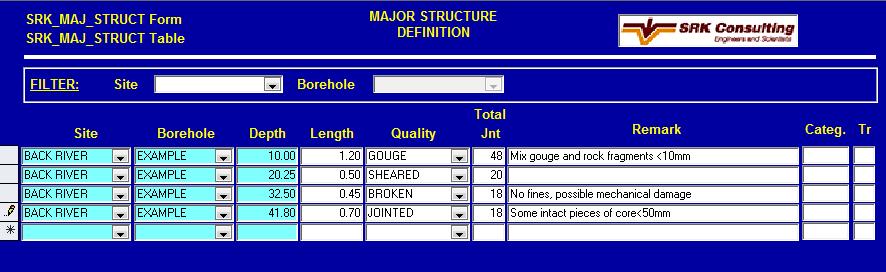
39 Major Structures

40 Recommended Methodology at Rig 1. Receive split tube from drill. 2. Fit the core together if loose in split. 3. Mark metres on core. 4. Clean core. 5. If core is orientated, continue the orientation line along the length of core. 6. Take a photo of the undisturbed core in the split tube. 7. Review core and determine potential geotechnical domains within the run. 8. Mark mechanical breaks, microdefects, and joints. 9. Review and comment on the drilling quality and notable features in the detailed log. 10. Conduct basic geotechnical logging, TCR and RQD. 11. Conduct orientation measurements and mark on drillcore; record offsets. 12. Conduct detailed geotechnical logging. 13. Take detailed photographs of specifics if required. 14. Label ends of core boxes to two decimal places. Other: note the base of casing depth in the database. Drill Hole Name Date: Logged By: From: To: DRY
 1 MODERATE (SOMETIMES BREAKS) 2 WEAK (ALWAYS BREAKS) Description Code Joint wall = Rock Hardness 1 Joint wall is Stronger than IRS 2 Joint wall")
41 JOINT ROUGHNESS Microdefect and Joint Descriptions JOINT WALL ALTERATION MICRO-DEFECT QUANTITY MICRODEFECTS - QUANTITY CODE DROP TEST - CJ/DEFECTS CODE DESCRIPTION 0 NONE 1 MINOR 2 MODERATE 3 HEAVY MICRO-DEFECT STRENGTH CATEGORY 0 STRONG (NEVER BREAKS) 1 MODERATE (SOMETIMES BREAKS) 2 WEAK (ALWAYS BREAKS) Description Code Joint wall = Rock Hardness 1 Joint wall is Stronger than IRS 2 Joint wall weaker than intact rock 3 JOINT FILLING Description Code GOUGE THICKNESS > AMPLITUDE 1 GOUGE THICKNESS < AMPLITUDE 2 SOFTENING - FINE 3 SOFTENING - MEDIUM 4 SOFTENING - COARSE 5 NON SOFTENING - FINE 6 NON SOFTENING - MEDIUM 7 NON SOFTENING - COARSE 8 STAINING ONLY 9 NONE 10 10cm

42 D) Oriented Core Logging

43 Core Orientation For angled holes, the drillers use a reflex product called an ACT or Ace Tool to determine the bottom of the hole for each run. The driller will mark the bottom of the hole on the end of the core for that run. Sometimes they may mark the top, indicated by a T. The geotech will use this mark to draw the bottom of hole orientation line on the core. Step by step instructions for this are provided in the manual. From this information, we can measure the orientation of joint planes, called the beta angles.
44 Orientation Line Offset If the orientation tool is being used correctly, and the geotech ensures that the rock is matched together when the orientation line is drawn, the bottom-of-hole orientation lines marked on each run should correspond from one run to the next. If the lines do not match, there is an offset, which is measured in degrees around the core, from the previous run s line to the current run s line, in a clockwise direction looking down the hole. The offset is recorded as a number between zero degrees and 360 degrees: Offset = 0 would indicate a perfect match between two orientation lines Offset = 10 would indicate that the new run is rotated clockwise by 10 degrees from the previous run Offset = 350 would indicate that the run is rotated clockwise by 350 degrees (or anticlockwise by 10 degrees) from the previous run At Back River we are recording this information in the basic log comments. Please indicate if there is no ori line available or the offset could not be determined because of the following reasons: Orientation line is marked on this run, but no offset could be measured because the run above did not have an orientation line. Orientation line is marked on this run, but no offset could be measured because the core from the run above did not match well with this run. No orientation line for this run.
45 Orientation Line Offset The geotech should make a comment about the orientation line, including their confidence in the offset measured. For example, if a section of the run was broken and difficult to put together, the geotech would indicate low confidence in the orientation for that run. Downhole direction O offset Offset 30. Correction of 30 needed. Operator error with tool? Offset 330. Looks back on track again. OL but no match. Broken end.
46 Alpha and Beta Angles We measure two angles on a joint: Alpha angles measure the joint dip, and are measured on every joint Beta angles measure orientation of the joint plane, and are only measured on joints with an orientation line β IS MEASURED CLOCKWISE TO THE BOTTOM OF THE ELIPSE. IN THIS CASE IT IS ~232º ORINTATION LINE ORIENTATION LIN DOWN-HOLE DIRECTION ORIENTATION STRIP SPECIFIC TO THE CORE SIZE BOTTOM OF ELLIPSE TO WHICH WE MEASURE THE β ANGLE α Α IS THE MAXIMUM DIP OF THE JOINT/FEATURE, RELATIVE TO THE CORE AXIS
: the carpenter angle is used to measure the maximum dip (α) of the feature relative to the core axis.")

47 Measuring Alpha and Beta Angles Measuring the required orientation parameters is done using a graduated strip and a carpenters angle. Alpha angle (α): the carpenter angle is used to measure the maximum dip (α) of the feature relative to the core axis. Beta angle (β): The plastic calibrated strip is placed with the 0 on the orientation line of the same piece of core and the tape is wrapped clockwise around the core so that the 360º point returns to the orientation line. The angle (β) is then measured, clockwise, from the orientation line to the most down hole part of the ellipse.
 angle measured Beta angle is")
 Alpha = 42 Beta")
48 Downhole direction Downhole direction Measuring Alpha and Beta Angles s Step 1 Step 2 Maximum dip (alpha) angle measured Beta angle is measured clockwise (in the downhole direction) around core from the orientation line Orientation line (marked previously) Alpha = 42 Beta = 134
Application of Core Logging Data to generate a 3D Geotechnical Block Model
 Application of Core Logging Data to generate a 3D Geotechnical Block Model Engineering Geology and Innovation: Research Infrastructure - Sustainable Development (I.A.E.G) Eleftheria Vagkli, M.Sc. Senior
Huaman A., Cabrera J. and Samaniego A. SRK Consulting (Peru) Introduction ABSTRACT
 Introduction ABSTRACT") Managing and validating limited borehole geotechnical information for rock mass characterization purposes experience in Peruvian practice for open pit mine projects Huaman A., Cabrera J. and Samaniego
Managing and validating limited borehole geotechnical information for rock mass characterization purposes experience in Peruvian practice for open pit mine projects Huaman A., Cabrera J. and Samaniego
Boreholes. Implementation. Boring. Boreholes may be excavated by one of these methods: 1. Auger Boring 2. Wash Boring 3.
 Implementation Boreholes 1. Auger Boring 2. Wash Boring 3. Rotary Drilling Boring Boreholes may be excavated by one of these methods: 4. Percussion Drilling The right choice of method depends on: Ground
Attachment F. Geotechnical Logging Procedures
 Attachment F Geotechnical Logging Procedures AREVA Resources Canada Inc. Kiggavik Project EIS December 2011 Attachment F Technical Appendix 6A Surficial Geology and Terrain Geotechnical Core Logging
Role of defects in rock mass classification
 Event 2013 A.A. Editor and B. Editor (eds) 2013 Australian Centre for Geomechanics, Perth, ISBN 978-0-98709xx-x-x Role of defects in rock mass classification J. Jakubec SRK Consulting (Canada) Ltd Abstract
Best practice rock engineering handbook for other mines
 Safety in Mines Research Advisory Committee Final Report Best practice rock engineering handbook for other mines T R Stacey Research Agency : SRK Consulting Project Number : OTH 602 Date : December 2001
An introduction to the Rock Mass index (RMi) and its applications
 and its applications") Reference: A. Palmström, www.rockmass.net An introduction to the Rock Mass index (RMi) and its applications by Arild Palmström, Ph.D. 1 Introduction Construction materials commonly used in civil engineering
Reference: A. Palmström, www.rockmass.net An introduction to the Rock Mass index (RMi) and its applications by Arild Palmström, Ph.D. 1 Introduction Construction materials commonly used in civil engineering
Evaluation of Structural Geology of Jabal Omar
 International Journal of Engineering Research and Development e-issn: 2278-067X, p-issn: 2278-800X, www.ijerd.com Volume 11, Issue 01 (January 2015), PP.67-72 Dafalla Siddig Dafalla * and Ibrahim Abdel
ENGINEERING GEOLOGY AND ROCK MECHANICS
 ENGINEERING GEOLOGY AND ROCK MECHANICS SKAA 2712 ENGINEERING PROPERTIES OF ROCK MASSES PROF. MADYA DR. EDY TONNIZAM BIN MOHAMAD DEPT. OF GEOTECHNICS AND TRANSPORTATION FACULTY OF CIVIL ENGINEERING UTM
ROCK MASS CHARATERISATION: A COMPARISON OF THE MRMR AND IRMR CLASSIFICATION SYSTEMS. G P Dyke AngloGold Ashanti 1
 ROCK MASS CHARATERISATION: A COMPARISON OF THE MRMR AND IRMR CLASSIFICATION SYSTEMS AngloGold Ashanti 1 Synopsis The MRMR Classification System was developed specifically for mining applications, namely
Geotechnical data from optical and acoustic televiewer surveys
 Geotechnical data from optical and acoustic televiewer surveys by Farrin De Fredrick MAusIMM, Senior Geotechnical Engineer; Ta Nguyen AIG, Geotechnical Engineer; Clive Seymour MAusIMM, Principal; and Gary
Instructional Objectives
 GE 6477 DISCONTINUOUS ROCK 3. Description of Discontinuities Dr. Norbert H. Maerz Missouri University of Science and Technology (573) 341-6714 norbert@mst.edu Instructional Objectives 1. List the ISRM
The MRMR Rock Mass Rating Classification System in Mining Practice
 The MRMR Rock Mass Rating Classification System in Mining Practice J Jakubec 1 and D H Laubscher 2 ABSTRACT The in situ rock mass rating system IRMR - leading to the mining rock mass rating system - MRMR
COMPARING THE RMR, Q, AND RMi CLASSIFICATION SYSTEMS
 COMPARING THE RMR, Q, AND RMi CLASSIFICATION SYSTEMS PART 2: CORRELATIONS OF THE THREE SYSTEMS by Arild Palmström, Ph.D. RockMass AS, Oslo, Norway In Part 1, it was shown how the input parameters to the
MEMORANDUM SUBJECT: CERTIFICATE IN ROCK MECHANICS PAPER 1 : THEORY SUBJECT CODE: COMRMC MODERATOR: H YILMAZ EXAMINATION DATE: OCTOBER 2017 TIME:
 MEMORANDUM SUBJECT: CERTIFICATE IN ROCK MECHANICS PAPER 1 : THEORY EXAMINER: WM BESTER SUBJECT CODE: COMRMC EXAMINATION DATE: OCTOBER 2017 TIME: MODERATOR: H YILMAZ TOTAL MARKS: [100] PASS MARK: (60%)
Empirical Design in Geotechnical Engineering
 EOSC433: Geotechnical Engineering Practice & Design Lecture 5: Empirical Design (Rock Mass Classification & Characterization) 1of 42 Erik Eberhardt UBC Geological Engineering EOSC 433 (2013) Empirical
Rotary Drilling Rotary Drilling Bits
 GE 343 SUBSURFACE EXPLORATION CH 8 Rock Drilling, Testing, and Sampling Text Ch. 7. Dr. Norbert H. Maerz Missouri University of Science and Technology (573) 341-6714 norbert@mst.edu Instructional Objectives
Underground Excavation Design Classification
 Underground Excavation Design Underground Excavation Design Classification Alfred H. Zettler alfred.zettler@gmx.at Rock Quality Designation Measurement and calculation of RQD Rock Quality Designation index
Instructional Objectives
 GE 343 SUBSURFACE EXPLORATION CH 8 Rock Drilling, Testing, and Sampling Text Ch. 7. Dr. Norbert H. Maerz Missouri University of Science and Technology (573) 341-6714 norbert@mst.edu Instructional Objectives
Burt G. Look Published online on: 10 Feb 2014
 This article was downloaded by: 10.3.98.93 On: 07 Apr 2019 Access details: subscription number Publisher: CRC Press Informa Ltd Registered in England and Wales Registered Number: 1072954 Registered office:
NNN99. Rock Engineering for the Next Very Large Underground Detector. D. Lee Petersen CNA Consulting Engineers
 NNN99 Rock Engineering for the Next Very Large Underground Detector D. Lee Petersen Overview Rock engineering 101 Cavern size & shape Construction methods Feasibility Historical projects Numerical modeling
Open Pit Rockslide Runout
 EOSC433/536: Geological Engineering Practice I Rock Engineering Lecture 5: Empirical Design & Rock Mass Characterization 1of 46 Erik Eberhardt UBC Geological Engineering EOSC 433 (2017) Open Pit Rockslide
Introduction and Background
 Introduction and Background Itasca Consulting Group, Inc. (Itasca) has been participating in the geomechanical design of the underground 118-Zone at the Capstone Minto Mine (Minto) in the Yukon, in northwestern
Ring Blasting Design Modeling and Optimization
 Ring Blasting Design Modeling and Optimization María Rocha, Rocha Blast Engineers, Spain & Roberto Laredo, Real Miners Consulting S.L., Spain Benjamín Cebrián, Blast-Consult S.L., Spain Abstract Ring blasting
Appendix 3. Sample Descriptions
 39 Appendix 3. Sample Descriptions 41 Appendix 3. Sample descriptions. HRM-01 Bates Lake Area 11D/13 (0423452/4956547) HRM-02 Bates Lake Area 11D/13 (0423010/4957749) HRM-03 Bates Lake Area 11D/13 (0422900/4957059)
SITE INVESTIGATION 1
 SITE INVESTIGATION 1 Definition The process of determining the layers of natural soil deposits that will underlie a proposed structure and their physical properties is generally referred to as site investigation.
ph electrode Instruction Manual For use with the RAH-210 & RPH-250
 ph electrode Instruction Manual For use with the RAH-210 & RPH-250 The information in this manual was current at the time of printing. The most current versions of all Hydro Instruments manuals can be
INFLUENCE OF AIR-DECK LENGTH ON FRAGMENTATION IN QUARRY BLASTING
 INFLUENCE OF AIR-DECK LENGTH ON FRAGMENTATION IN QUARRY BLASTING Suttithep Rommayawes, MS Rajamangala University of Technology Lanna (RMUTL), Thailand Chewchan Leelasukseree, PhD Pirat Jaroonpattanapong,
Instructional Objectives. Why use mass classification? What is rock mass classification? 3 Pillars of empirical design and rock mass classification
 GE 6477 DISCONTINUOUS ROCK 5. Rock Mass Classification and Empirical Design Dr. Norbert H. Maerz Missouri University of Science and Technology (573) 341-6714 norbert@mst.edu Instructional Objectives 1.
Title: Author: Background: Maximise core recovery: Identify and resolve orientation and data transfer issues at rig:
 Title: HOW TO MAXIMISE THE QUALITY AND VALUE OF STRUCTURAL DATA FOR YOUR PROJECT - A PRACTICAL GUIDE TO COMMON PROBLEMS WITH FIELD DATA TRANSFER WHEN ORIENTATING CORE. Author: Gavin McLeod Background:
Chapter 12 Subsurface Exploration
 Page 12 1 Chapter 12 Subsurface Exploration 1. The process of identifying the layers of deposits that underlie a proposed structure and their physical characteristics is generally referred to as (a) subsurface
HANDBOOK. Using the Q-system. Rock mass classification and support design
 HANDBOOK Using the Q-system Rock mass classification and support design Oslo, April 2013 For further information on this handbook please contact: NGI Postboks 3930 Ullevål Stadion 0806 OSLO Norway www.ngi.no
How to Interpret Mining Company Drill Reports & Announcements
 How to Interpret Mining Company Drill Reports & Announcements A Simple Guide amscot Stockbroking Pty Ltd A division of State One Stockbroking Ltd (AFSL 247 100) Disclaimer: All information in this document
Instituto De Ingenieros De Minas Del Peru
 The Continuity Challenge Dr. Wayne Barnett The Interpretation! Great geological continuity? Huge potential? The Reality Not what it might seem... Not what it might seem... Presentation Objective Highlight
PLANES OF WEAKNESS IN ROCKS, ROCK FRCTURES AND FRACTURED ROCK. Contents
 PLANES OF WEAKNESS IN ROCKS, ROCK FRCTURES AND FRACTURED ROCK Contents 7.1 Introduction 7.2 Studies On Jointed Rock Mass 7.2.1 Joint Intensity 7.2.2 Orientation Of Joints 7.2.3 Joint Roughness/Joint Strength
Quantitative Classification of Rock Mass
 Quantitative Classification of Rock Mass Description of Joints: Orientation, Persistence, Roughness, Wall Strength, Aperture, Filling, Seepage, Number of sets, Block size, spacing. ISRM commission s i
Module 9 : Foundation on rocks. Content
 FOUNDATION ON ROCKS Content 9.1 INTRODUCTION 9.2 FOUNDATION TYPES ON ROCKS 9.3 BEARING CAPCITY- SHALLOW FOUNDATION 9.3.1 Ultimate bearing capacity 9.3.2 Safe bearing pressure 9.3.3 Estimation of bearing
The process of determining the layers of natural soil deposits that will underlie a proposed structure and their physical properties is generally
 The process of determining the layers of natural soil deposits that will underlie a proposed structure and their physical properties is generally referred to as sub surface investigation 2 1 For proper
Use of RMR to Improve Determination of the Bearing Resistance of Rock
 Creating Value Delivering Solutions Use of RMR to Improve Determination of the Bearing Resistance of Rock Scott Zang, P.E. Michael Baker Jr., Inc. ASD Design Q v allowable is a presumptive allowable bearing
Lab 3: Minerals and the rock cycle. Rocks are divided into three major categories on the basis of their origin:
 Geology 101 Name(s): Lab 3: Minerals and the rock cycle Rocks are divided into three major categories on the basis of their origin: Igneous rocks (from the Latin word, ignis = fire) are composed of minerals
Gotechnical Investigations and Sampling
 Gotechnical Investigations and Sampling Amit Prashant Indian Institute of Technology Gandhinagar Short Course on Geotechnical Investigations for Structural Engineering 12 14 October, 2017 1 Purpose of
GUIDELINE FOR HAND HELD SHEAR VANE TEST
 GUIDELINE FOR HAND HELD SHEAR VANE TEST NZ GEOTECHNICAL SOCIETY INC August 2001 CONTENTS Page 1.0 Introduction 2 2.0 Background 2 3.0 Recommended Practice 3 4.0 Undrained Shear Strength 3 5.0 Particular
Estimation of rock cavability in jointed roof in longwall mining
 University of Wollongong Research Online Coal Operators' Conference Faculty of Engineering and Information Sciences 2013 Estimation of rock cavability in jointed roof in longwall mining Alireza Jabinpoor
LICENTIATE THESIS. Evaluation of rock mass strength criteria. Catrin Edelbro
 LICENTIATE THESIS Evaluation of rock mass strength criteria Catrin Edelbro Department of Civil and Environmental Engineering Division of Rock Mechanics BACKGROUND BACKGROUND Correct input data Reliable
GEOTECHNICAL INVESTIGATION REPORT
 GEOTECHNICAL INVESTIGATION REPORT SOIL INVESTIGATION REPORT FOR STATIC TEST FACILITY FOR PROPELLANTS AT BDL, IBRAHIMPATNAM. Graphics Designers, M/s Architecture & Engineering 859, Banjara Avenue, Consultancy
Geotechnical project work flow
 Wulf Schubert INTRODUCTION The approach to solve an engineering problem is to combine experience with analysis The more complex the conditions are, the more difficult a direct analysis becomes, as appropriate
Session 3: Geology and Rock Mechanics Fundamentals
 Session 3: Geology and Rock Mechanics Fundamentals Geotechnical Engineering Appreciation Course (Jointly organised by IES Academy and GeoSS) Dr Zhou Yingxin, Senior Principal Engineer, DSTA Adjuct Associate
PHYSICO-MECHANICAL PROPERTIES OF ROCKS LECTURE 2. Contents
 PHYSICO-MECHANICAL PROPERTIES OF ROCKS LECTURE 2 Contents 2.1 Introduction 2.2 Rock coring and logging 2.3 Physico-mechanical properties 2.3.1 Physical Properties 2.3.1.1 Density, unit weight and specific
Geotechnical Models and Data Confidence in Mining Geotechnical Design
 Geotechnical Models and Data Confidence in Mining Geotechnical Design Michael Dunn Principal Consultant (Geotechnical Engineering) Overview Geotechnical models Geotechnical model and design Data reliability
 SOIL CLASSIFICATION CHART COARSE-GRAINED SOILS MORE THAN 50% RETAINED ON NO.200 SIEVE FINE-GRAINED SOILS 50% OR MORE PASSES THE NO.200 SIEVE PRIMARY DIVISIONS GRAVELS MORE THAN 50% OF COARSE FRACTION RETAINED
RMR and SMR as Slope Stability Preliminary Studies of Rajamandala Limestone Mine Area
 1th Asian Regional Conference of IAEG () RMR and SMR as Slope Stability Preliminary Studies of Rajamandala Limestone Mine Area Ilham PRASETYA (1), Rizqi NARENDRA (1), Agus WIRAMSYA (), Irvan SOPHIAN (),
LOGGING AND SAMPLING PROTOCOL
 LOGGING AND SAMPLING PROTOCOL The following discussion will address a number of issues including; the physical taking of the samples, geological descriptions, sample numbering and handling, and the dispatch
ROCK MASS PROPERTIES FOR TUNNELLING
 ROCK MASS PROPERTIES FOR TUNNELLING Robert Bertuzzi 2 nd November 2017 1 Driver Estimating the strength and deformation characteristics of a rock mass for tunnel design is generally based on empiricism
Rock slope rock wedge stability
 Engineering manual No. 28 Updated: 02/2018 Rock slope rock wedge stability Program: Rock stability File: Demo_manual_28.gsk The aim of the chapter of this engineering manual is to explain a rock slope
Rock Material. Chapter 3 ROCK MATERIAL HOMOGENEITY AND INHOMOGENEITY CLASSIFICATION OF ROCK MATERIAL
 Chapter 3 Rock Material In all things of nature there is something of the marvelous. Aristotle ROCK MATERIAL The term rock material refers to the intact rock within the framework of discontinuities. In
11 Years Engineering Geology Fieldwork in Falset, Salou, and Cambrils. Science From Fieldwork
 11 Years Engineering Geology Fieldwork in Falset, Salou, and Cambrils Science From Fieldwork What did we Produce? Why did we? 14 dec 2001 11 years engineering geology in Falset - science from fieldwork
Site investigation in rock
 Site investigation in rock masses Geotechnical Core Drilling & Logging Core Orientation Borehole Surveying Logging g Core Borehole Log Face Mapping Scanline Data Analysis Influence of Joints Orientation
7. Foundation and Slope Stability
 The Asian Nuclear Safety Network 7. Foundation and Slope Stability (SER 2.5.4 & 2.5.5) Taek-Mo SHIM k147stm@kins.re.kr Korea Institute of Nuclear Safety Structural Systems and Site Evaluation Department
P Forsmark site investigation. Borehole: KFM01A Results of tilt testing. Panayiotis Chryssanthakis Norwegian Geotechnical Institute, Oslo
 P-03-108 Forsmark site investigation Borehole: KFM01A Results of tilt testing Panayiotis Chryssanthakis Norwegian Geotechnical Institute, Oslo June 2003 Svensk Kärnbränslehantering AB Swedish Nuclear Fuel
CHAPTER FIVE CLASSIFICATION OF SHEAR STRENGTH OF JOINTS IN ROCK
 CHAPTER FIVE CLASSIFICATION OF SHEAR STRENGTH OF JOINTS IN ROCK 5.1 Introduction The shear strength of joint surfaces in a rock mass is a difficult parameter to determine. Several researchers, including
Rock Mechanical Aspects of Roadheader Excavation
 Rock Mechanical Aspects of Roadheader Excavation Uwe Restner Sandvik Mining and Construction G.m.b.H., Hard Rock Continuous Mining, Zeltweg, Austria Ralf J. Plinninger Dr. Plinninger Geotechnik, Bernried,
Page 4.1 Overview 4-3
 Chapter 4 Contents Page 4.1 Overview 4-3 4.2 Soil Classification 4-3 4.2.1 Coarse Grained Soils 4-4 4.2.2 Fine-Grained Inorganic Soils 4-7 4.2.3 Organic Fine Grained Soils 4-7 4.2.4 Angularity 4-10 4.2.5
Collection and use of geological data in rock engineering
 Published in ISRM News Journal, 997, pp. - Collection and use of geological data in rock engineering by Arild Palmström "I see almost no research effort being devoted to the generation of the basic input
Lab I. 2D Motion. 1 Introduction. 2 Theory. 2.1 scalars and vectors LAB I. 2D MOTION 15
 LAB I. 2D MOTION 15 Lab I 2D Motion 1 Introduction In this lab we will examine simple two-dimensional motion without acceleration. Motion in two dimensions can often be broken up into two separate one-dimensional
EROSIONAL FEATURES. reflect
 reflect Have you ever looked at the land around you and wondered what processes shaped what you see? Perhaps you see mountains, valleys, rivers, or canyons. Do you know how long these geologic features
STRUCTURAL GEOLOGY. Deformation
 eformation STRUCTURAL GEOLOGY Styles of deformation These items can be used to demonstrate different styles of deformation to the class. To show elastic deformation: elastic band, sponge or plastic ruler,
Horizontal Stress. US Stress Regimes: In the eastern United States:
 Horizontal Stress 1. In the last 30 years, horizontal stress has been recognized as a major component of ground control problems. 2. In general, the horizontal stresses found in coal mines are caused by
Core Barrels. Core Barrels
 Core Barrels To collect the core of the rock drilled, a device known as the core barrel is used. Core barrel retains rock core samples from drilling operations Its length varies from 0.5 to 3 m. There
BOREHOLE ID: SRKGW2A. Geological Profile. Borehole Construction and Water level. Description. Complete. 0.04l/s. Slight. 0.04l/s. Coordinate System:
 BOREHOLE ID: SRKGW2A COA22 33.7868 /8/214 1.7429 318 6.68 22 2 Fern Isle,Section 1 Tel: +27()11 789 949 PVC cased - 22 Highly weathered 1 1 Fine chips, highly weathered gabbro 1 1 2 2 Drilled radius 2,
Electric Field Mapping
 Electric Field Mapping Equipment: mapping board, U-probe, 5 resistive boards, templates, knob adjustable DC voltmeter, 4 long leads, 16 V DC for wall strip, 8 1/2 X 11 sheets of paper Reading: Topics of
Geology 229 Engineering Geology. Lecture 7. Rocks and Concrete as Engineering Material (West, Ch. 6)
") Geology 229 Engineering Geology Lecture 7 Rocks and Concrete as Engineering Material (West, Ch. 6) Outline of this Lecture 1. Rock mass properties Weakness planes control rock mass strength; Rock textures;
Geology 229 Engineering Geology Lecture 7 Rocks and Concrete as Engineering Material (West, Ch. 6) Outline of this Lecture 1. Rock mass properties Weakness planes control rock mass strength; Rock textures;
Establishing a site specific mining geotechnical logging atlas
 Establishing a site specific mining geotechnical logging atlas B.A. Murphy &.R. Campbell SRK Consulting, Vancouver ABSTRACT: In many instances geotechnical training and the generation of geotechnical logging
WARNING. INJURY HAZARD Failure to observe these instructions could lead to severe injury or death.
 INSTALLATION INSTRUCTIONS ATV Front Plow Mount Kit Part Number: 80031 Applications: 2007+ Honda Rancher 420 2007+ Honda Rancher ES 420 2009+ Honda Rancher AT 420 *Not compatible with 2.5ci or A2000 winches
Further Research into Methods of Analysing the October 2000 Stability of Deep Open Pit Mines EXECUTIVE SUMMARY
 EXECUTIVE SUMMARY This report presents the results of a program of further research into the use of a combined approach of numerical and centrifuge modeling in assessing the stability of deep open pit
Lab I. 2D Motion. 1 Introduction. 2 Theory. 2.1 scalars and vectors LAB I. 2D MOTION 15
 LAB I. 2D MOTION 15 Lab I 2D Motion 1 Introduction In this lab we will examine simple two-dimensional motion without acceleration. Motion in two dimensions can often be broken up into two separate one-dimensional
LITHOLOGY REPORT - Detailed -
 (m) (m) Lithology Sample # Length 50 0.00 11.76 10 Casing Minor Interval: 0.00 0.54 10A Casing above ground (Air) 0.54 11.76 10G Casing through gravel or overburden (Ground) 11.76 40.80 1c Interbedded
APPENDIX A. Borehole Logs Explanation of Terms and Symbols
 APPENDIX A Borehole Logs Explanation of Terms and Symbols Page 153 of 168 EXPLANATION OF TERMS AND SYMBOLS The terms and symbols used on the borehole logs to summarize the results of field investigation
RQD Slope stability classification Weathering
 RQD Slope stability classification Weathering Robert Hack Engineering Geology, ESA, International Institute for Geoinformation Sciences and Earth Observation (ITC) The Netherlands Dehradun, India, 23 September
Appendix J. Geological Investigation
 Appendix J Geological Investigation Appendix J Geological Environment Table of Contents Page 1 INTRODUCTION...J-1 1.1 Purpose of the Investigation...J-1 1.2 Scope of the Investigation...J-1 2 METHODO OF
Ch. 4 - Clay Minerals, Rock Classification Page 1. Learning Objectives. Wednesday, January 26, 2011
 Ch. 4 - Clay Minerals, Rock Classification Page 1 Learning Objectives Ch. 4 - Clay Minerals, Rock Classification Page 2 Symbols Ch. 4 - Clay Minerals, Rock Classification Page 3 Clay Minerals and Structure
Name: Period: Date: Sedimentary Rock Lab (Formation, Properties, and Ancient Depositional Environments)
") Name: Period: Date: Sedimentary Rock Lab (Formation, Properties, and Ancient Depositional Environments) BIG IDEA: Earth s immense history is recorded in the rocks. Sedimentary rocks tell us about ancient
Name: Period: Date: Sedimentary Rock Lab (Formation, Properties, and Ancient Depositional Environments) BIG IDEA: Earth s immense history is recorded in the rocks. Sedimentary rocks tell us about ancient
Guideline for Rock Mass Classification System
 Japan Sri Lanka Guideline for February 2018 Table of Contents 1 Introduction... 1 2 Geological and Geotechnical Condition of Sri Lanka... 5 2.1 Sri Lanka... 5 2.1.1 Geology... 5 2.1.2 Geotechnical Conditions...
B) color B) Sediment must be compacted and cemented before it can change to sedimentary rock. D) igneous, metamorphic, and sedimentary rocks
 color B) Sediment must be compacted and cemented before it can change to sedimentary rock. D) igneous, metamorphic, and sedimentary rocks") 1. Which characteristic of nonsedimentary rocks would provide the least evidence about the environment in which the rocks were formed? A) structure B) color C) crystal size D) mineral composition 2. Which
1. Which characteristic of nonsedimentary rocks would provide the least evidence about the environment in which the rocks were formed? A) structure B) color C) crystal size D) mineral composition 2. Which
Step by Step Instructions
 Step by Step Instructions DAY ONE Teacher Preparation: Prepare cups with layer of plasticene at base, middle layer of coarse salt and upper layer of plasticine. Make sure each plasticine layer has a good
Improving slope stability at Kışladağ Gold Mine
 Improving slope stability at Kışladağ Gold Mine S. Ergun, E. Gungor & B. Ozdemir Eldorado Gold Corporation / Tuprag, Usak, Turkey S. Esen Drill and Blast Consultant, Sydney, Australia ABSTRACT: This paper
GLG598 Surface Processes and Landform Evolution K. Whipple Fall 2012 VERDE RIVER: FLOW MECHANICS, ROUGHNESS, AND SHEAR STRESS
 VERDE RIVER: FLOW MECHANICS, ROUGHNESS, AND SHEAR STRESS This lab will introduce you to some common field techniques and some general understanding of the geomorphic processes operating in a stream. The
DESCRIPTION OF THE TESTS AND DATA USED IN THE CALIBRATION OF THE RMi
 From Palmström A.: RMi a rock mass characterization system for rock engineering purposes. PhD thesis, Oslo University, Norway, 1995, 400 p. APPENDIX 6 DESCRIPTION OF THE TESTS AND DATA USED IN THE CALIBRATION
MULTIVARIATE ANALYSIS OF BORE HOLE DISCONTINUITY DATA
 Maerz,. H., and Zhou, W., 999. Multivariate analysis of bore hole discontinuity data. Rock Mechanics for Industry, Proceedings of the 37th US Rock Mechanics Symposium, Vail Colorado, June 6-9, 999, v.,
ENGINEERING GEOLOGY AND ROCK ENGINEERING
 1 ENGINEERING GEOLOGY AND ROCK ENGINEERING HANDBOOK NO. 2 Norwegian Group for Rock Mechanics (NBG) www.bergmekanikk.com Prepared in co-operation with Norwegian Tunnelling Society (NFF) Issued in 2000 SECRETARIAT:
 Project: ITHACA-TOMPKINS REGIONAL AIRPORT EXPANSION Project Location: ITHACA, NY Project Number: 218-34 Key to Soil Symbols and Terms TERMS DESCRIBING CONSISTENCY OR CONDITION COARSE-GRAINED SOILS (major
A. V T = 1 B. Ms = 1 C. Vs = 1 D. Vv = 1
 Geology and Soil Mechanics 55401 /1A (2002-2003) Mark the best answer on the multiple choice answer sheet. 1. Soil mechanics is the application of hydraulics, geology and mechanics to problems relating
Geology and Soil Mechanics /1A ( ) Mark the best answer on the multiple choice answer sheet.
 Mark the best answer on the multiple choice answer sheet.") Geology and Soil Mechanics 55401 /1A (2003-2004) Mark the best answer on the multiple choice answer sheet. 1. Soil mechanics is the application of hydraulics, geology and mechanics to problems relating
Geology and Soil Mechanics 55401 /1A (2003-2004) Mark the best answer on the multiple choice answer sheet. 1. Soil mechanics is the application of hydraulics, geology and mechanics to problems relating
B-1 BORE LOCATION PLAN. EXHIBIT Drawn By: 115G BROOKS VETERINARY CLINIC CITY BASE LANDING AND GOLIAD ROAD SAN ANTONIO, TEXAS.
 N B-1 SYMBOLS: Exploratory Boring Location Project Mngr: BORE LOCATION PLAN Project No. GK EXHIBIT Drawn By: 115G1063.02 GK Scale: Checked By: 1045 Central Parkway North, Suite 103 San Antonio, Texas 78232
ENCE 3610 Soil Mechanics. Site Exploration and Characterisation Field Exploration Methods
 ENCE 3610 Soil Mechanics Site Exploration and Characterisation Field Exploration Methods Geotechnical Involvement in Project Phases Planning Design Alternatives Preparation of Detailed Plans Final Design
Minerals and Rocks. Rocks
 Minerals and Rocks Rocks What do you think? Read the two statements below and decide whether you agree or disagree with them. Place an A in the Before column if you agree with the statement or a D if you
Manual on Subsurface Investigations National Highway Institute Publication No. FHWA NHI Federal Highway Administration Washington, DC
 Manual on Subsurface Investigations National Highway Institute Publication No. FHWA NHI-01-031 Federal Highway Administration Washington, DC Geotechnical Site Characterization July 2001 by Paul W. Mayne,
APPENDIX C SUBSURFACE EXPLORATIONS
 APPENDIX C SUBSURFACE EXPLORATIONS 51-1-52-021 APPENDIX C SUBSURFACE EXPLORATIONS TABLE OF CONTENTS Page C.1. C.2. C.3. C.4. C.5. C.6. GENERAL...C-1 DRILLING PROCEDURES...C-1 SAMPLING PROCEDURES...C-2
The effect of discontinuities on stability of rock blocks in tunnel
 International Journal of the Physical Sciences Vol. 6(31), pp. 7132-7138, 30 November, 2011 Available online at http://www.academicjournals.org/ijps DOI: 10.5897/IJPS11.777 ISSN 1992-1950 2011 Academic
Measurement of effective stress shear strength of rock
 Measurement of effective stress shear strength of rock R. A. Failmezger, P.E., F. ASCE In-Situ Soil Testing, L.C., Lancaster, Virginia USA D. J. White, Ph. D., P.E. Iowa State University, Ames, Iowa USA
Rock Mechanics and Seismology Laboratory
 CAEE 211 Geology Laboratory 6 Lab Date: 29 July 2016 Rock Mechanics and Seismology Laboratory Due Date: 5 August 2016 Attendance (based on signing): 30 points Submitting Student Name: Members of laboratory