Lab 2: Projecting Geographic Data
|
|
|
- Dorothy Webb
- 5 years ago
- Views:
Transcription

1 Lab 2: Projecting Geographic Data What you ll Learn: Basic methods for map projections in ArcGIS Pro. What You ll Produce: A map of Minnesota in three different statewide projections, a map of reprojected Minnesota county boundaries with an inset global view, and notes recording areas and coordinates for various projections and measurements. Your recorded measurements will be entered into a Canvas Lab 2 Worksheet Data Entry Worksheet. Background: Chapter 3 of the GIS Fundamentals textbook provides the necessary background. We introduce unavoidable distortion when we flatten the Earth s curved surface onto a flat map. Different map projections represent the same points with different X and Y (or E and N) coordinate values. We cannot mix map projections in an analysis, so we often have to re-project some of our data layers. Note that in the instructions below we often use the terms map projection, projection, and coordinate system interchangeably. A map projection is associated with a specific coordinate system, and to project data is to convert from one coordinate system to another. Data: For this exercise the data is on the Lab2 shared lab drive, L:\FNRM3131 or FNRM5131 or the class website; remember copy the lab data folder for each lab to your L:\home\{your id} for use in ArcGIS Pro. See last week s instructions or the Quickstart Guide on the lab page if you don t remember how to access them. Observing How Distance May Change with a Map Projection Start ArcGIS Pro, and add two Maps (see last week s instructions if you ve forgotten how). Remove any default base topography and map layers that ArcGIS Pro might have added. Name one of the Map windows Albers, and name the other Map Mercator (Video: Rename map & set measure units) Activate the Alber s Layer (right click map tab along the top edge of the map view) Add the layers twocity_albers.shp, and USA_48_Albers.shp from the Lab2 folder. Make sure the Map tab is selected/active. 1
2 Left click on the Measure Tool to enable it, and set the Distance Units to Miles, and Mode to Planar. Left-click once on Los Angeles, then move the mouse to New York and double left-click on New York. The distance between the two cites is displayed in a drop-down window. Your measured distance should be approximately 2,440 miles. Activate the Mercator Map. Add the layers twocity_mercator.shp, USA_48_Mercator.shp Re-measure the distance from LA to NY. The new measurement should be approximately 3,127 miles. The on the ground distance between LA and NY is actually 2,444 miles. The difference in measurements between the Albers and Mercator is due to unavoidable distortion caused when we stretch measurements from the curved Earth surface to a flat map surface. Notice that the distortion is different for different projections. Change the Mode in the measure tool to Geodesic and repeat the two distance measurements. You should get approximately the same number. Under the Geodesic option, the calculations approximate as close as possible the true distance measurement on the surface of the earth. The Loxodromic and Great Elliptical options are only slightly different than the Geodesic differences, but are approximately equal to the Geodesic distance in this application. The big difference is with the planar method, which assumes both projections are good approximations of a Cartesian surface. You can see, with the almost 700 mile error, that a Cartesian measurement assumption can be substantially wrong. Coordinates and On the Fly Projection We want to introduce the idea of a temporary, or on the fly projection, something that ArcGIS Pro often does when you add data to a Map (Video: On the fly projection). A Map usually has a specified coordinate system. You can manually set the system, or ArcGIS Pro can establish one automatically when you first load data. Once a coordinate system for a Map has been specified, ArcGIS Pro will display the approximate coordinates of the current cursor location along the bottom of the Map frame (see the arrow below). Create a new Map, and add the minn_count_dd data. This is a data layer of Minnesota county boundaries in decimal degrees coordinates. 2
, and then left click on the Attribute Table option in the dropdown list: This should display")
3 First look at the attribute table. Lab 2: Projections Right click over the layer name in the table of contents (on the left of your window), and then left click on the Attribute Table option in the dropdown list: This should display the attributes associated with this polygon layer. Note that the table may be tiled in with your other open windows, so you may have to grab the edges with your cursor to resize the panes. There is a Name item, containing the name of each county. We ll use this to label the counties (See the Video: Labels). We ll use this column to label each polygon with the county name. 3
, and then click on the label icon at the extreme left to turn labeling on. You should see the labels appear on your Map.")

4 Left click on the tab toward the right center of the main window, under Feature Layer, Labeling. This will display the labeling ribbon, as shown above. We select and style labels using these tools. Select Name in the field window at the lower left (see figure above), and then click on the label icon at the extreme left to turn labeling on. You should see the labels appear on your Map. Depending on the settings, they may not show up at first, and you may have to zoom in on the Map for them to display. You can set threshold scales above/below which labels appear, and also rules that omit overlapping labels. You can use the tools to change the font properties, label angles, and other characteristics. Close the table (click on the x at the right edge of the tab), and then zoom to display the northeast corner of Ramsey County, in the east-central portion of Minnesota (see figure at right) Move your cursor and notice the coordinates near the bottom-center of the Map. These are cursor coordinates, in this case for the data layer you first loaded to the Map, here decimal degrees (Video: Coordinate Query). 4
5 Your Map may be displaying some other coordinate units, depending on if you displayed another layer previously, or your system default preferences are different from those we used. To change the display coordinate units while navigating around the map: -right click on the Map name in the Table of Contents at the left of the Map, then -left click on Properties, then select General from the displayed list (Video: Rename Map and Set Measure Units) This will reveal several options, including setting the map units, and display units. About half-way down you can set the display units, make sure they are set to Decimal Degrees. Click on OK to close the window, and verify that the units at the base of the Map are displayed as decimal degrees. Zoom in and reposition the cursor successively until you have an accurate reading for the coordinates of the northeast corner of Ramsey County (see the figure above). You ll know you re zoomed in enough when the coordinate values don t change or only change in the third decimal place when you move slightly off of the displayed corner. Record (write down) the decimal degree coordinates of the northeast corner of Ramsey County. Keep this written information, as you will have more coordinates to look up later in this exercise. 5
6 Every data layer has a coordinate system associated with it. A Map may have a different coordinate system. ArcGIS Pro will temporarily convert the layer coordinates to the Map system (if it can), so that data will be displayed in the proper relative locations. This way we can display data from several different sources, each in different coordinate systems, together at the same time. The layer data are not changed in storage, they are only temporarily projected on the fly to align correctly. Sometimes this doesn t work, for example, when the information on the coordinate system for a layer is missing or corrupted, but usually everything works as planned. You may view and set the coordinate system for a Map, to which every layer is temporarily projected by right clicking on the Map, and then selecting Properties from the dropdown (as you did earlier), but this time left clicking on Coordinate System in the displayed window: This shows the Map is set to the WGS84 GCS, or Geographic Coordinate System. All data will be projected to this system when displayed. 6
 Contiguous USA Albers On hitting OK, the properties window")
 We can view the coordinate system for a data layer (not a Map) by right clicking on the data layer, then")
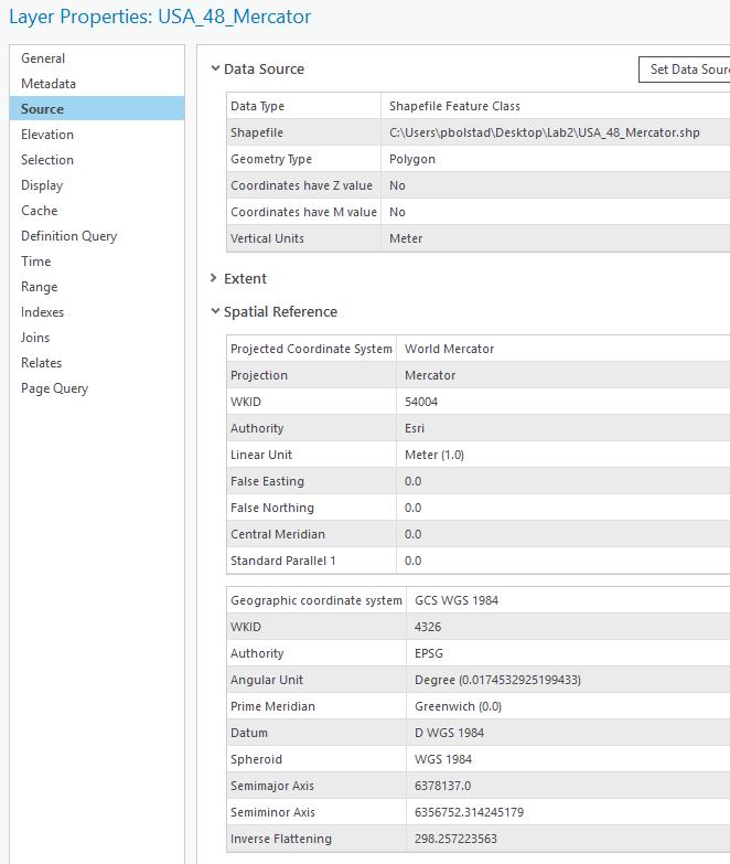
7 We can change this (Video: Set the Map Window Projection). For example, in the Map Properties/Coordinate Systems window select : Projected coordinate system Continental North America NAD83(2011) Contiguous USA Albers On hitting OK, the properties window should disappear and the counties change shape and orientation a bit, from this: To a less flattened: Switch the Map coordinate system back to the WGS84 (with the Map selected, right click for Properties, then left click Coordinate systems, Geographic coordinate system, World, WGS84) We can view the coordinate system for a data layer (not a Map) by right clicking on the data layer, then left click on Properties, then Source This allows us to inspect layer properties including the Spatial Reference, describing the coordinate system. 7
, and the data show the particular properties Add the USA_48_Mercator to the same Map.")
8 Left click on the Spatial Reference option, and view the spatial reference information, in a window similar to the figure below. This shows the characteristics of the layer s coordinate system. This is a geographic coordinate system (latitudes/longitudes), and the data show the particular properties Add the USA_48_Mercator to the same Map. Position the layers so the Minnesota county data are on top (click and drag up/down layers). Open the Properties Source tab for this data layer, and it should display something like the window on the next page. Note it displays more information than the GCS WGS84 for the minn_count_dd layer, above. The Mercator layer has both a projection, here a World Mercator, and an underlying GCS. As noted in the readings, projected coordinate systems have both parts, and underlying GCS and then a projection, while geographic systems have only a GCS, but are not projected. 8

9 9 Lab 2: Projections


10 Zoom to the full extent of the USA_48_Mercator, you should have something like the image below: Note that although the different data sets are in different projections, they line up on top of each other. Why? The layers line up because ArcGIS Pro is doing an on the fly projection, as described earlier. Now set the Map coordinate system to that of the USA_48_Mercator layer. Do this with through a left click on the Map in the TOC, then select Properties, Coordinate System, then Layers, World Mercator You ll notice ArcGIS Pro puts the coordinate systems for all layers in a Map in a list at the top of the Map Properties window, for easy selection. Notice after you click OK, the layers change shape slightly, as they are temporarily reprojected 10


11 to this new coordinate system. Lab 2: Projections This can be quite confusing at first, but you need make sure you understand this concept of a Map coordinate system, with temporary reprojection, and a data layer coordinate system the coordinate system the data are stored in. If you understand this difference, you will likely save yourself much confusion and grief. Why is this important? Some operations won t work correctly if data layers are in different coordinate systems, for example some editing, overlays, or distance measurements. You may think they are in the same system if you display them together, but your geo-calculations may be wrong. Sometimes you will be confused in interpreting data, or mis-identify the coordinates because data are re-projected temporarily for display. If you have any questions about the coordinate system of a layer, look at the layer properties, as shown above. Let s explore this further, by changing the Map coordinate system via the Map Properties window: Click on the Projected Coordinate Systems, then Continental, then North America, then the NAD83 Contiguous USA Albers, then O.K. This is a common projection for the lower 48 U.S. states. Zoom to full layer, and notice it changes the shape of the US and Minnesota data, to look something like: Notice the curve on the western half of the northern border, compared to previous views. The data on disk have not been changed, they ve just been temporarily reprojected to this specific Albers coordinate system. 11


12 Change the Map coordinate system again, this time selecting Projected Coordinate Systems UTM NAD NAD83 UTM Zone 12 N Zoom to full extent, and display the data, noting the change in the projection, as at right. Finally, switch the Map coordinate system again, this time back to the Geographic Coordinate Systems North America->USA and territories NAD83 Note the change in shape. We haven t changed the projection of the data on the disk, we ve just told ArcGIS Pro to project on the fly, to a new system, before display. It is generally o.k. to mix data from several coordinate systems in a Map. However, you should be careful when performing operations that alter or create new coordinates, because there could be some ambiguity in which coordinate system ArcGIS Pro will choose to use. It is best to either run a small test to verify the specific ArcGIS tool, or to convert all the data to a common coordinate system permanently, saving to new layers (we ll show how to do this later in the lab), so that all your data are in the same coordinate system before manipulating x-y values. You should also be careful when performing area calculations with mixed data sets, because it is easy to become confused about the units of the outputs. 12


13 Creating an Inset Map We can use this temporary projection to create an inset map in a different coordinate system. You created an inset map last week, but both the main and thumbnail maps had the same coordinate system. This time we ll different coordinate systems for the inset and main map. First, if you haven t saved and closed your last project, do so now, and create a new ArcGIS Pro project by clicking on the upperleftmost icon for the main window: After the Map opens, remove any default layers that might be loaded. Open the Map Properties window, note that the Current XY coordinate system is set to WGS 1984 Web Mercator. We can change the defaults. You don t need to, but if you re curious, left click on the Project tab in the main window, then Options about half way down, then Maps and Scenes. You can set a default basemap, coordinate system, and affect the behavior of added layers. Note that if the first layer we load has a different coordinate system than the default, ArcGIS Pro will change the coordinate system for the layer to the Map, but only for the first layer. To reiterate, loading a data layer into a new Map sets the Map coordinate system to that of the layer; all subsequent layers will be projected, if possible, on-the-fly to this original system while being displayed. To illustrate, Add the minn_county.shp layer to the empty Map. Verify via Map Properties that the Map coordinate system has now been changed to NAD_1983_UTM_Zone_15N. Adding layers with different 13

14 coordinate systems after this first one will not change the Map coordinate system automatically. Rename this first Map Minnesota Counties. Now, insert a new Map, and name it Earth From Space. Again, verify that the Map has the WGS Mercator coordinate system Now change the coordinate system for the Map manually: Open the Map properties, and set the Coordinate System for the Map to: Projected Coordinate Systems World The World from Space Add three data layers to this new Map: Countries (boundaries of the World s countries in 1990, in geographic coordinates) minn_county (Minnesota counties, in UTM Zone 15N coordinates), and graticule15 (lines of constant latitude and longitude, at 15 degree intervals) Re-arrange the layers so the graticule is on top in the TOC, then the minn_count layer second, with the Countries layer at the bottom. Symbolize the minn_count layer so it is a solid bright color, and Countries polygons so they are a light or pastel, and the graticule as a thin black line, so that you have something like the figure at right. Rename the Map something like Space View (right click on the map in the Catalog on right (not Table of Contents, on left), and select rename; see earlier instructions, if unsure). Now switch to the Map, Minnesota Counties. Zoom to the data layer full extent so that all of the data are visible in your Minnesota Counties Map, then switch to the Space View Map, and also zoom to full extent. Create a layout view (see last week s lab). Notice there are boxes for each frame. They may overlap, so you may have to click one and hold to drag aside. Move and resize the boxes, perhaps also going back to the data view and panning/zooming, so that the Minnesota State box is larger, and the US/Minnesota combined data are about 1/6 th the size, as in many inset maps (see figure below). 14


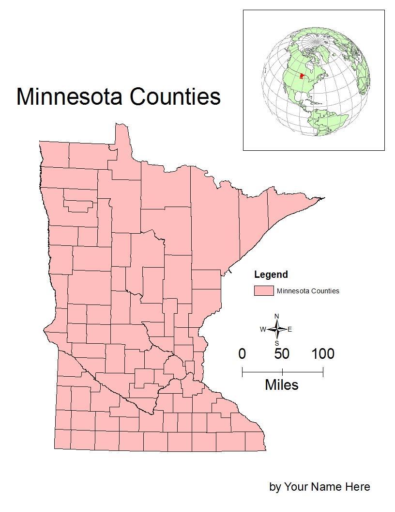
15 You may have to change the scale, particularly for the globe inset, use the scale box on an active map as described in last week s lab. You have two different Maps in this common map design, with a small inset showing general location in one coordinate system, and a larger panel in a different coordinate system showing detail for the highlighted portion of the inset. Note that each panel has a bounding box or frame around it in the layout view. The larger bounding box interferes with the inset You can remove this bounding box by: right clicking on the box, opening a map formatting option panel on the right side of your main window: left click on the paintbrush icon, and modify the border symbol to make it colorless Add a North arrow, caption, your name, a legend, and descriptive title, and export/print a PDF, as instructed last week. See an example below of the map you should produce. Although you need not exactly match the colors and positions, make sure to include a proportioned main map and inset, a descriptive title, your name, a north arrow, and scale bar. A final point about on-the fly-projections. You may obtain data that has been projected to a coordinate system, but for which the identity of the coordinate system has been lost. This is most common with shapefiles, where the coordinate system information is stored in a.prj file, e.g., minn_county.prj. If the file is lost, damaged, mis-specified, or not copied with the rest of the shape files, then the ArcGIS Pro program can t identify the layer s coordinate system. If you know the coordinate system for a file, you can add the prj file back or fix it for a geodatabase through a tool we ll describe in the next section. 15
16 16 Lab 2: Projections

17 Projecting Data to a New File The Project Tool The above section describes on the fly projection, which changes coordinate values temporarily so they may be viewed together. However, we often want to permanently project a data set from one coordinate system to another, creating a new data set in a different projected coordinate system. We accomplish this in ArcGIS with the Project tool. Each time we apply the Project tool, we identify the source data set, the output data set, and the output projection. Most source data sets have a coordinate system associated with them. The Project tool reads this coordinate system to determine the input. We then specify the output, including the datum transformation, if needed, and save the new file to a target location. There is another tool, the Define Projection tool, which is much more rarely used. The Define Projection tool changes information within a layer about the name of the projection. It doesn t change any coordinates. You ONLY use the Define Projection tool when you know the projection name for a layer is missing or incorrectly recorded. The toolbox is shown at the right, but don t look for it or try to use it now, we ll describe how in the next section of this lab. We include it here to emphasize that these two tools that are often confused. You only use the Define Projection tool when you have a projected data layer, you know what the projection identity is, but that projection identity has been corrupted or erased from the layer. If you don t know a layer s projection, you need to either 1) identify it unambiguously by matching coordinates or overlaying with other data, or 2( discard the data, because it isn t very useful without knowledge of the projected coordinate system. The Define Projection tool is often confused with the Project tool, listed just below Define Projection in the figure above). The Project tool is more commonly used, and converts a layer from one coordinate system to another. It reads the information in a layer about its coordinate system, and then re-projects the data to another known coordinate system, and modifies the information in the layer. DON T USE THE DEFINE PROJECTION TOOL WHEN YOU SHOULD USE THE PROJECT TOOL. Sorry for the all caps shouting, but this is a very common mistake in the remainder of this exercise, and worse, in practice. You can easily ruin data and not know it by mis-applying the Define Projection tool. It s too bad ESRI named them as they did, as this often confuses the new or occasional user, but such is life. 17
18 (Video: Project). Save your previous work and close any open projects. Open a new one, insert three new empty Maps; remove any default layers that might be loaded. Name the Maps Albers, UTM, and Mercator Left click on the Analysis Tab along the top margin, then click on the Tools toolbox, the little red toolbox along the icon ribbon, then click on Toolboxes, the middle label in the right-side column (see arrows, below). This should display a list of available tools along the right side of your window, as shown. 18
19 To project data, click on Lab 2: Projections Data Management Tools then Projections and Transformations then Project The Project tool converts data from one coordinate system to another, saving the projected data to a new file. 19
20 Detailed instructions for specific projection examples are provided a bit further on in this document, but the general process is to start the Project tool, and then: Select a data layer containing the features you want to convert to a new coordinate system Specify an output location and name for a new data layer Specify the output projection, and if need be, a datum transformation (Arc calls it a Geographic Transformation, the same thing as the datum transformation described in the textbook Apply the projection Remember, ArcGIS shapefiles store information about the projection in a.prj file. For example, a layer named minn_county_dd may have projection information stored in the file minn_county_dd.prj. Without a.prj, ArcGIS Pro is ignorant of the projection system, so you may have to specify the input as well as output projections in the general steps above. Using the Project Tool This section will step you through the projection screens. You will have to use these steps several more times in this Lab (Video: Project). In later iterations, refer back to this sequence. We assume you have three empty Maps in the same project, one named Albers, one UTM, and one named Mercator. If not, create them now. Make the Albers Map active. Double click on the Project Tool the previous figure. in the ArcToolbox, located as shown in This should open a Geoprocessing tab and menu in the right-most column of the main ArcGIS Pro window: This allows you to specify the input and output files, the Output coordinate system, and if needed, a Geographic Transformation (more commonly called a Datum Transformation). Click on the folders to the right of the input and output data set windows to specify the input and output files. Use the mn_count_dd.shp as the input. Name the output MN_Count_Alb, and place it in the L:\home directory with your input data and project. 20
21 Next, specify the output coordinate system by clicking on the globe to the right of the entry row in the Geoprocessing window: This should open a window in which you specify the target cooridinate system. The window looks quite like the one used to specify a Map coordinate system: You use the carets to drop down lists, until you eventually select a specific output projection. The Geographic caret accesses all geographic coordinate systems (GCS), meaning you would project to a lat/lon, spherical system. The Projected caret accesses common Cartesian projections. Left click on Projected coordinate system then Continental then North American Then NAD 1983 Contiguous USA Albers then 21
_To_NAD_1983: Click on the Run button in the lower")
: Inspect the coordinate system for the MN_Count_Alb data")
22 OK at the bottom of the window. Lab 2: Projections This should automatically choose the appropriate Geographic Transformation, WGS84(ITRF00)_To_NAD_1983: Click on the Run button in the lower right corner of the Geogprocessing column: After a bit of processing, a message should show across the bottom of the Geoprocessing column indicating successful completion, and the projected data should be placed in your active map window (that you named Albers): Inspect the coordinate system for the MN_Count_Alb data layer you just created, remember, by first right clicking on the name in the TOC, then Properties, Source, Spatial Reference 22


23 This should display the spatial reference information for the layer, showing NAD 1983 Contiguous USA Albers as the projected coordinate system: 23
24 Project to a UTM Coordinate System Activate Map you name UTM, Lab 2: Projections Use the Project tool again, with - input as the minn_county_dd data - a new output data set, named UTM15_minncounty, - an output coordinate system via Projected Coordinate Systems, then UTM, then NAD83, then NAD83 UTM Zone 15N Click on OK to apply the projection, which should load the data to your Map named UTM Zone 15N. Again, verify that you have the correct output by inspecting the information on the layer. Project to a Mercator Coordinate System Activate your last Map, that you named Mercator Use the Project tool in ArcToolbox one more time, with - input once again as the minn_county_dd data - a new output data set, named MN_county_Mercator, Projected Coordinate Systems, then World, then Mercator (world) Again, verify the projection on the output data layer after it displays in your Mercator map. 24

25 Now you should have three different Maps, with three different versions of the Minnesota counties an Albers, a UTM, and a Mercator. Notice the shapes are different, not so much between the Albers and UTM, but noticeably so for the Mercator relative to the other two. Activate the measure tool, Set the mode to distance units to kilometers, and the Mode to Planar Measure Distances from the northeastern-most point of Minnesota to the southwester most point for each of your three projections. Do this as carefully as you can, it pays to expand the Map window to as large as will fit on your screen. Write down the distances, perhaps on the lab 2 worksheet at the back of this lab, to be entered for online grading later. Also, record the coordinates for the northeast corner of Ramsey County for all three coordinate systems, as you did for the decimal degrees display at the start of this lab. Remember to zoom way in on the northeast corner of the county to get the most accurate coordinates: 1:10 at least. Write the coordinates down for the Albers, UTM, and custom Mercator projection layers. When you submit your two PDF s for the Lab into Canvas, also use the Lab 2 Worksheet Data Entry quiz to enter your handwritten recorded coordinates and distances. 25

26 Create a map with all three Minnesota projections We wish to create a map with all three projections: Lab 2: Projections remove any default layers that might be loaded. For a fair comparison, we ll need to set a fixed scale for each of the Maps. (Video: SetLayoutScale) First, Select the Insert tab, then select New Layout, then select the ANSI-Landscape Letter mode Drag each of the Map boxes from the Catalog column (you may have to first select the Catalog tab at the lower part of the right column), and arrange them to be side by side and about the same size. You may want to change the colors of the layers in each data view for easy identification, you do this by activating the respective maps, and changing the layer color in the TOC. First click on the layout if it isn t activated, then a Map, then Display Options, and type in the desired scale (see figure below). 26

27 Third, click on The Display Options Icon to activate it First click on the Layout tab to activate it Second click on a displayed map to select it, a margin should appear around it Fourth, type in the scale, e.g., to set a scale of 1:10,000,000 Set the scale for each Make each the same scale, something near 1:10,000,000 or so. Note you shouldn t type in the 1: or the commas into the window, we show them here for clarity. Make sure you choose the same fixed scale for each Map. Note the default is a border around each Map in the layout view, and the map looks better if you remove them, as shown before (click on Map in Layout, then on the Format Map Frame tab, click on the paintbrush icon and modify the border). Add a name, North Arrow, title, and scalebar, and individual titles for each Map (see example). Note that you don t need to add a legend. 27
28 Below is a sample of the notes you will take during this lab, writing down distances and coordinates that you will record on the Canvas Lab 2 Worksheet Data Entry quiz Distance across Minnesota, from northeast to southwest, in kilometers: Albers: UTM Zone 15N: Custom Mercator: Coordinates of northeast corner of Ramsey County: Projection x-coordinate y-coordinate Albers (Meters) UTM Zone 15 (Meters) Custom Mercator (Meters) 28
Lab 2: Projecting Geographic Data
 Lab 2: Projecting Geographic Data What you ll Learn: Basic methods for map projections in ArcMap. What You ll Produce: A map of Minnesota in three different statewide projections, a map of reprojected
Geography 281 Map Making with GIS Project Eight: Comparing Map Projections
 Geography 281 Map Making with GIS Project Eight: Comparing Map Projections In this activity, you will do a series of projection comparisons using maps at different scales and geographic extents. In this
Trouble-Shooting Coordinate System Problems
 Trouble-Shooting Coordinate System Problems Written by Barbara M. Parmenter. Revised on October 2, 2018 OVERVIEW OF THE EXERCISE... 1 COPYING THE MAP PROJECTION EXERCISE FOLDER TO YOUR H: DRIVE OR DESKTOP...
Data Structures & Database Queries in GIS
 Data Structures & Database Queries in GIS Objective In this lab we will show you how to use ArcGIS for analysis of digital elevation models (DEM s), in relationship to Rocky Mountain bighorn sheep (Ovis
Task 1: Start ArcMap and add the county boundary data from your downloaded dataset to the data frame.
 Exercise 6 Coordinate Systems and Map Projections The following steps describe the general process that you will follow to complete the exercise. Specific steps will be provided later in the step-by-step
IDENTIFYING THE TYPE OF COORDINATE SYSTEM FOR DATA USING ARCMAP
 CHAPTER 1 IDENTIFYING THE TYPE OF COORDINATE SYSTEM FOR DATA USING ARCMAP I got a parcel shapefile from the county, but it doesn t line up with my other data in ArcMap. My boss told me to make a map using
Trouble-Shooting Coordinate System Problems
 Trouble-Shooting Coordinate System Problems Written by Barbara M. Parmenter, revised 2/25/2014 OVERVIEW OF THE EXERCISE... 1 COPYING THE MAP PROJECTION EXERCISE FOLDER TO YOUR H: DRIVE OR DESKTOP... 2
Displaying Latitude & Longitude Data (XY Data) in ArcGIS
 in ArcGIS") Displaying Latitude & Longitude Data (XY Data) in ArcGIS Created by Barbara Parmenter and updated on 2/15/2018 If you have a table of data that has longitude and latitude, or XY coordinates, you can view
Displaying Latitude & Longitude Data (XY Data) in ArcGIS Created by Barbara Parmenter and updated on 2/15/2018 If you have a table of data that has longitude and latitude, or XY coordinates, you can view
The data for this lab comes from McDonald Forest. We will be working with spatial data representing the forest boundary, streams, roads, and stands.
 GIS LAB 6 Using the Projection Utility. Converting Data to Oregon s Approved Lambert Projection. Determining Stand Size, Stand Types, Road Length, and Stream Length. This lab will ask you to work with
(THIS IS AN OPTIONAL BUT WORTHWHILE EXERCISE)
") PART 2: Analysis in ArcGIS (THIS IS AN OPTIONAL BUT WORTHWHILE EXERCISE) Step 1: Start ArcCatalog and open a geodatabase If you have a shortcut icon for ArcCatalog on your desktop, double-click it to start
PART 2: Analysis in ArcGIS (THIS IS AN OPTIONAL BUT WORTHWHILE EXERCISE) Step 1: Start ArcCatalog and open a geodatabase If you have a shortcut icon for ArcCatalog on your desktop, double-click it to start
Identifying coordinate systems for data using ArcMap
 Chapter 1 Identifying coordinate systems for data using ArcMap I got a parcel shapefile from the county but it doesn t line up with my other data in ArcMap. My boss told me to make a map using ArcMap,
The Geodatabase Working with Spatial Analyst. Calculating Elevation and Slope Values for Forested Roads, Streams, and Stands.
 GIS LAB 7 The Geodatabase Working with Spatial Analyst. Calculating Elevation and Slope Values for Forested Roads, Streams, and Stands. This lab will ask you to work with the Spatial Analyst extension.
Tutorial 8 Raster Data Analysis
 Objectives Tutorial 8 Raster Data Analysis This tutorial is designed to introduce you to a basic set of raster-based analyses including: 1. Displaying Digital Elevation Model (DEM) 2. Slope calculations
Working with ArcGIS: Classification
 Working with ArcGIS: Classification 2 Abbreviations D-click R-click TOC Double Click Right Click Table of Content Introduction The benefit from the use of geographic information system (GIS) software is
GEOREFERENCING, PROJECTIONS Part I. PRESENTING DATA Part II
 Week 7 GEOREFERENCING, PROJECTIONS Part I PRESENTING DATA Part II topics of the week Georeferencing Coordinate systems Map Projections ArcMap and Projections Geo-referencing Geo-referencing is the process
GIS Workshop UCLS_Fall Forum 2014 Sowmya Selvarajan, PhD TABLE OF CONTENTS
 TABLE OF CONTENTS TITLE PAGE NO. 1. ArcGIS Basics I 2 a. Open and Save a Map Document 2 b. Work with Map Layers 2 c. Navigate in a Map Document 4 d. Measure Distances 4 2. ArcGIS Basics II 5 a. Work with
MERGING (MERGE / MOSAIC) GEOSPATIAL DATA
 GEOSPATIAL DATA") This help guide describes how to merge two or more feature classes (vector) or rasters into one single feature class or raster dataset. The Merge Tool The Merge Tool combines input features from input
This help guide describes how to merge two or more feature classes (vector) or rasters into one single feature class or raster dataset. The Merge Tool The Merge Tool combines input features from input
Downloading GPS Waypoints
 Downloading Data with DNR- GPS & Importing to ArcMap and Google Earth Written by Patrick Florance & Carolyn Talmadge, updated on 4/10/17 DOWNLOADING GPS WAYPOINTS... 1 VIEWING YOUR POINTS IN GOOGLE EARTH...
Watershed Modeling Orange County Hydrology Using GIS Data
 v. 10.0 WMS 10.0 Tutorial Watershed Modeling Orange County Hydrology Using GIS Data Learn how to delineate sub-basins and compute soil losses for Orange County (California) hydrologic modeling Objectives
In this exercise we will learn how to use the analysis tools in ArcGIS with vector and raster data to further examine potential building sites.
 GIS Level 2 In the Introduction to GIS workshop we filtered data and visually examined it to determine where to potentially build a new mixed use facility. In order to get a low interest loan, the building
Lesson Plan 2 - Middle and High School Land Use and Land Cover Introduction. Understanding Land Use and Land Cover using Google Earth
 Understanding Land Use and Land Cover using Google Earth Image an image is a representation of reality. It can be a sketch, a painting, a photograph, or some other graphic representation such as satellite
Working with Map Projections
 Working with Map Projections Rachel Applebaum and Margaret M. Maher Author of Lining Up Data in ArcGIS: a guide to map projections Second edition Some common problems that prevent data from aligning correctly
Lab 1: Importing Data, Rectification, Datums, Projections, and Coordinate Systems
 Lab 1: Importing Data, Rectification, Datums, Projections, and Coordinate Systems Topics covered in this lab: i. Importing spatial data to TAS ii. Rectification iii. Conversion from latitude/longitude
Exercise 3: GIS data on the World Wide Web
 Exercise 3: GIS data on the World Wide Web These web sites are a few examples of sites that are serving free GIS data. Many other sites exist. Search in Google or other search engine to find GIS data for
CE 365K Exercise 1: GIS Basemap for Design Project Spring 2014 Hydraulic Engineering Design
 CE 365K Exercise 1: GIS Basemap for Design Project Spring 2014 Hydraulic Engineering Design The purpose of this exercise is for you to construct a basemap in ArcGIS for your design project. You may execute
Catchment Delineation Workflow
 Catchment Delineation Workflow Slide 1 Given is a GPS point (Lat./Long.) for an outlet location. The outlet could be a proposed Dam site, a storm water drainage culvert on a rural highway, or any other
Learning ArcGIS: Introduction to ArcCatalog 10.1
 Learning ArcGIS: Introduction to ArcCatalog 10.1 Estimated Time: 1 Hour Information systems help us to manage what we know by making it easier to organize, access, manipulate, and apply knowledge to the
Delineation of Watersheds
 Delineation of Watersheds Adirondack Park, New York by Introduction Problem Watershed boundaries are increasingly being used in land and water management, separating the direction of water flow such that
Experiment 13. Dilutions and Data Handling in a Spreadsheet rev 1/2013
 Absorbance Experiment 13 Dilutions and Data Handling in a Spreadsheet rev 1/2013 GOAL: This lab experiment will provide practice in making dilutions using pipets and introduce basic spreadsheet skills
caused displacement of ocean water resulting in a massive tsunami. II. Purpose
 I. Introduction The Great Sumatra Earthquake event took place on December 26, 2004, and was one of the most notable and devastating natural disasters of the decade. The event consisted of a major initial
How to Make or Plot a Graph or Chart in Excel
 This is a complete video tutorial on How to Make or Plot a Graph or Chart in Excel. To make complex chart like Gantt Chart, you have know the basic principles of making a chart. Though I have used Excel
How to Create Stream Networks using DEM and TauDEM
 How to Create Stream Networks using DEM and TauDEM Take note: These procedures do not describe all steps. Knowledge of ArcGIS, DEMs, and TauDEM is required. TauDEM software ( http://hydrology.neng.usu.edu/taudem/
Vector Analysis: Farm Land Suitability Analysis in Groton, MA
 Vector Analysis: Farm Land Suitability Analysis in Groton, MA Written by Adrienne Goldsberry, revised by Carolyn Talmadge 10/9/2018 Introduction In this assignment, you will help to identify potentially
Global Atmospheric Circulation Patterns Analyzing TRMM data Background Objectives: Overview of Tasks must read Turn in Step 1.
 Global Atmospheric Circulation Patterns Analyzing TRMM data Eugenio Arima arima@hws.edu Hobart and William Smith Colleges Department of Environmental Studies Background: Have you ever wondered why rainforests
Assignment #0 Using Stellarium
 Name: Class: Date: Assignment #0 Using Stellarium The purpose of this exercise is to familiarize yourself with the Stellarium program and its many capabilities and features. Stellarium is a visually beautiful
WindNinja Tutorial 3: Point Initialization
 WindNinja Tutorial 3: Point Initialization 6/27/2018 Introduction Welcome to WindNinja Tutorial 3: Point Initialization. This tutorial will step you through the process of downloading weather station data
EOS 102: Dynamic Oceans Exercise 1: Navigating Planet Earth
 EOS 102: Dynamic Oceans Exercise 1: Navigating Planet Earth YOU MUST READ THROUGH THIS CAREFULLY! This exercise is designed to familiarize yourself with Google Earth and some of its basic functions while
ENV101 EARTH SYSTEMS
 ENV101 EARTH SYSTEMS Practical Exercise 2 Introduction to ArcMap and Map Projections 1. OVERVIEW This practical is designed to familiarise students with the use of ArcMap for visualising spatial data and
Using Microsoft Excel
 Using Microsoft Excel Objective: Students will gain familiarity with using Excel to record data, display data properly, use built-in formulae to do calculations, and plot and fit data with linear functions.
Modeling Incident Density with Contours in ArcGIS Pro
 Modeling Incident Density with Contours in ArcGIS Pro By Mike Price, Entrada/San Juan, Inc. What you will need ArcGIS Pro 1.4 license or later ArcGIS Spatial Analyst license ArcGIS Online for organizational
OneStop Map Viewer Navigation
 OneStop Map Viewer Navigation» Intended User: Industry Map Viewer users Overview The OneStop Map Viewer is an interactive map tool that helps you find and view information associated with energy development,
Lab 1: Importing Data, Rectification, Datums, Projections, and Output (Mapping)
") Lab 1: Importing Data, Rectification, Datums, Projections, and Output (Mapping) Topics covered in this lab: i. Importing spatial data to TAS ii. Rectification iii. Conversion from latitude/longitude to
Lab 1: Importing Data, Rectification, Datums, Projections, and Output (Mapping) Topics covered in this lab: i. Importing spatial data to TAS ii. Rectification iii. Conversion from latitude/longitude to
Handling Raster Data for Hydrologic Applications
 Handling Raster Data for Hydrologic Applications Prepared by Venkatesh Merwade Lyles School of Civil Engineering, Purdue University vmerwade@purdue.edu January 2018 Objective The objective of this exercise
Lab#3: GIS Projections and Coordinate Systems. Start Arcmap and create a data frame for each of the above coordinate systems.
 NRM338 Fall 2017 Lab#3 Page#1 of 18 In this lab, you will Lab#3: GIS Projections and Coordinate Systems 1) Define the geographic coordinate system of two GIS themes. 2) Determine the geographic coordinates
Studying Topography, Orographic Rainfall, and Ecosystems (STORE)
") Studying Topography, Orographic Rainfall, and Ecosystems (STORE) Introduction Basic Lesson 3: Using Microsoft Excel to Analyze Weather Data: Topography and Temperature This lesson uses NCDC data to compare
Studying Topography, Orographic Rainfall, and Ecosystems (STORE) Introduction Basic Lesson 3: Using Microsoft Excel to Analyze Weather Data: Topography and Temperature This lesson uses NCDC data to compare
Create Satellite Image, Draw Maps
 Create Satellite Image, Draw Maps 1. The goal Using Google Earth, we want to create and import a background file into our Adviser program. From there, we will be creating paddock boundaries. The accuracy
Projection and Reprojection
 Using Quantum GIS Tutorial ID: IGET_GIS_002 This tutorial has been developed by BVIEER as part of the IGET web portal intended to provide easy access to geospatial education. This tutorial is released
Presenting Tree Inventory. Tomislav Sapic GIS Technologist Faculty of Natural Resources Management Lakehead University
 Presenting Tree Inventory Tomislav Sapic GIS Technologist Faculty of Natural Resources Management Lakehead University Suggested Options 1. Print out a Google Maps satellite image of the inventoried block
Geographers Perspectives on the World
 What is Geography? Geography is not just about city and country names Geography is not just about population and growth Geography is not just about rivers and mountains Geography is a broad field that
GST 101: Introduction to Geospatial Technology Lab 3 - Understanding Coordinate Systems and Map Projections
 GST 101: Introduction to Geospatial Technology Lab 3 - Understanding Coordinate Systems and Map Projections Objective Explore and Understand Coordinate Systems and Map Projections Document Version: 3/3/2015
Lab#8: Working With Geodatabases. create a geodatabase with feature datasets, tables, raster datasets, and raster catalogs
 Lab#8: Geodatabase Concepts Page#1 of 25 In this lab, you will learn how to: Lab#8: Working With Geodatabases create a geodatabase with feature datasets, tables, raster datasets, and raster catalogs join
GIS in Management Planning. Lab 2 Coordinate Systems and Map Projections
 GIS in Management Planning Lab 2 Coordinate Systems and Map Projections Tomislav Sapic GIS Technologist Faculty of Natural Resources Management Lakehead University ArcGIS ArcToolbox Projections Functions
Geography 281 Map Making with GIS Project Four: Comparing Classification Methods
 Geography 281 Map Making with GIS Project Four: Comparing Classification Methods Thematic maps commonly deal with either of two kinds of data: Qualitative Data showing differences in kind or type (e.g.,
Exercise 4. Watershed and Stream Network Delineation
 Exercise 4. Watershed and Stream Network Delineation GIS in Water Resources, Fall 2017 Prepared by David G Tarboton and David R. Maidment Updated to ArcGIS Pro by Paul Ruess Purpose The purpose of this
Exercise 4. Watershed and Stream Network Delineation
 Exercise 4. Watershed and Stream Network Delineation GIS in Water Resources, Fall 2016 Prepared by David G Tarboton and David R. Maidment Updated to ArcGIS Pro by Paul Ruess [9/29/16 Further updated to
WORKING WITH DMTI DIGITAL ELEVATION MODELS (DEM)
") WORKING WITH DMTI DIGITAL ELEVATION MODELS (DEM) Contents (Ctrl-Click to jump to a specific page) Manipulating the DEM Step 1: Finding the DEM Tiles You Need... 2 Step 2: Importing the DEM Tiles into ArcMap...
WORKING WITH DMTI DIGITAL ELEVATION MODELS (DEM) Contents (Ctrl-Click to jump to a specific page) Manipulating the DEM Step 1: Finding the DEM Tiles You Need... 2 Step 2: Importing the DEM Tiles into ArcMap...
ArcGIS Pro: Essential Workflows STUDENT EDITION
 ArcGIS Pro: Essential Workflows STUDENT EDITION Copyright 2018 Esri All rights reserved. Course version 6.0. Version release date August 2018. Printed in the United States of America. The information contained
Lab #3 Map Projections.
 Lab #3 Map Projections http://visual.merriam-webster.com/images/earth/geography/cartography/map-projections.jpg Map Projections Projection: a systematic arrangement of parallels and meridians on a plane
Welcome to Lesson 4. It is important for a GIS analyst to have a thorough understanding of map projections and coordinate systems.
 Welcome to Lesson 4. It is important for a GIS analyst to have a thorough understanding of map projections and coordinate systems. A GIS without coordinates would simply be a database like Microsoft Excel
Within this document, the term NHDPlus is used when referring to NHDPlus Version 2.1 (unless otherwise noted).
.") Exercise 7 Watershed Delineation Using ArcGIS Spatial Analyst Last Updated 4/6/2017 Within this document, the term NHDPlus is used when referring to NHDPlus Version 2.1 (unless otherwise noted). There
Exercise 7 Watershed Delineation Using ArcGIS Spatial Analyst Last Updated 4/6/2017 Within this document, the term NHDPlus is used when referring to NHDPlus Version 2.1 (unless otherwise noted). There
This week s topics. Week 6. FE 257. GIS and Forest Engineering Applications. Week 6
 FE 257. GIS and Forest Engineering Applications Week 6 Week 6 Last week Chapter 8 Combining and splitting landscape features and merging GIS databases Chapter 11 Overlay processes Questions? Next week
GST 104: Cartographic Design Lab 2: Exploring Coordinate Systems and Map Projections
 GST 104: Cartographic Design Lab 2: Exploring Coordinate Systems and Map Projections Objective Explore and Understand Coordinate Systems and Map Projections Document Version: 2014-05-31 (Beta) Author:
ArcGIS for Applied Economists Session 2
 ArcGIS for Applied Economists Session 2 Mark Westcott LMU Munich June 15, 2015 1 / 31 Topics for this session: Geographic Coordinate Systems Projections Projected Coordinate Systems Geocoding 2 / 31 Some
Lab 7: Cell, Neighborhood, and Zonal Statistics
 Lab 7: Cell, Neighborhood, and Zonal Statistics Exercise 1: Use the Cell Statistics function to detect change In this exercise, you will use the Spatial Analyst Cell Statistics function to compare the
Exercise 4. Watershed and Stream Network Delineation
 Exercise 4. Watershed and Stream Network Delineation GIS in Water Resources, Fall 2014 Prepared by David G Tarboton and David R. Maidment Purpose The purpose of this exercise is to illustrate watershed
Experiment: Oscillations of a Mass on a Spring
 Physics NYC F17 Objective: Theory: Experiment: Oscillations of a Mass on a Spring A: to verify Hooke s law for a spring and measure its elasticity constant. B: to check the relationship between the period
Exercises for Windows
 Exercises for Windows CAChe User Interface for Windows Select tool Application window Document window (workspace) Style bar Tool palette Select entire molecule Select Similar Group Select Atom tool Rotate
Studying Topography, Orographic Rainfall, and Ecosystems (STORE)
") Introduction Studying Topography, Orographic Rainfall, and Ecosystems (STORE) Lesson: Using ArcGIS Explorer to Analyze the Connection between Topography, Tectonics, and Rainfall GIS-intensive Lesson This
Introduction Studying Topography, Orographic Rainfall, and Ecosystems (STORE) Lesson: Using ArcGIS Explorer to Analyze the Connection between Topography, Tectonics, and Rainfall GIS-intensive Lesson This
Your work from these three exercises will be due Thursday, March 2 at class time.
 GEO231_week5_2012 GEO231, February 23, 2012 Today s class will consist of three separate parts: 1) Introduction to working with a compass 2) Continued work with spreadsheets 3) Introduction to surfer software
Overlay Analysis II: Using Zonal and Extract Tools to Transfer Raster Values in ArcMap
 Overlay Analysis II: Using Zonal and Extract Tools to Transfer Raster Values in ArcMap Created by Patrick Florance and Jonathan Gale, Edited by Catherine Ressijac on March 26, 2018 If you have raster data
Preparing Spatial Data
 13 CHAPTER 2 Preparing Spatial Data Assessing Your Spatial Data Needs 13 Assessing Your Attribute Data 13 Determining Your Spatial Data Requirements 14 Locating a Source of Spatial Data 14 Performing Common
How to Convert USGS Topographic GeoPDF 1 Maps to GeoTIFF using ArcGIS 10.4
 How to Convert USGS Topographic GeoPDF 1 Maps to GeoTIFF using ArcGIS 10.4 This tutorial assumes that you have: 1) downloaded some USGS geopdfs, 2) a pdf reader such as Adobe Acrobat, and 3) ArcGIS 10.4
Urban Canopy Tool User Guide `bo`
 Urban Canopy Tool User Guide `bo` ADMS Urban Canopy Tool User Guide Version 2.0 June 2014 Cambridge Environmental Research Consultants Ltd. 3, King s Parade Cambridge CB2 1SJ UK Telephone: +44 (0)1223
Physics E-1ax, Fall 2014 Experiment 3. Experiment 3: Force. 2. Find your center of mass by balancing yourself on two force plates.
 Learning Goals Experiment 3: Force After you finish this lab, you will be able to: 1. Use Logger Pro to analyze video and calculate position, velocity, and acceleration. 2. Find your center of mass by
Exercise 6: Coordinate Systems
 Exercise 6: Coordinate Systems This exercise will teach you the fundamentals of Coordinate Systems within QGIS. In this exercise you will learn: How to determine the coordinate system of a layer How the
Task 1: Open ArcMap and activate the Spatial Analyst extension.
 Exercise 10 Spatial Analyst The following steps describe the general process that you will follow to complete the exercise. Specific steps will be provided later in the step-by-step instructions component
Environmental Systems Research Institute
 Introduction to ArcGIS ESRI Environmental Systems Research Institute Redlands, California 2 ESRI GIS Development Arc/Info (coverage model) Versions 1-7 from 1980 1999 Arc Macro Language (AML) ArcView (shapefile
In order to follow this exercise you need to have completed exercise 1.
 In order to follow this exercise you need to have completed exercise 1. Contents of Exercise 2: Derive new datasets from inputs and carry out Multicriteria analysis in order to Part 1: Use Spatial Analysis
Prosurv LLC Presents
 Prosurv LLC Presents An Enterprise-Level Geo-Spatial Data Visualizer Part IV Upload Data Upload Data Click the Upload Data menu item to access the uploading data page. Step #1: Select a Project All Projects
Introduction to ArcGIS 10.2
 Introduction to ArcGIS 10.2 Francisco Olivera, Ph.D., P.E. Srikanth Koka Lauren Walker Aishwarya Vijaykumar Keri Clary Department of Civil Engineering April 21, 2014 Contents Brief Overview of ArcGIS 10.2...
ArcGIS 9 ArcGIS StreetMap Tutorial
 ArcGIS 9 ArcGIS StreetMap Tutorial Copyright 2001 2008 ESRI All Rights Reserved. Printed in the United States of America. The information contained in this document is the exclusive property of ESRI. This
Lecture Plan. GEOL 452/552 - GIS for Geoscientists I. Why use Projections? Lecture 15 - chapter 11. Different types of Projections
 GEOL 452/552 - GIS for Geoscientists I Lecture 15 - chapter 11 Lecture Plan Ch. 11, one lecture Coordinate systems Projection, Datums, Dpheroid Unprojected (geographic) coord. syst., UTM On the fly projection
Exercise 4. Watershed and Stream Network Delineation
 Exercise 4. Watershed and Stream Network Delineation GIS in Water Resources, Fall 2018 Prepared by David G Tarboton and David R. Maidment Revised 9 October, 2018 Purpose The purpose of this exercise is
Introduction to Computer Tools and Uncertainties
 Experiment 1 Introduction to Computer Tools and Uncertainties 1.1 Objectives To become familiar with the computer programs and utilities that will be used throughout the semester. To become familiar with
Moving into the information age: From records to Google Earth
 Moving into the information age: From records to Google Earth David R. R. Smith Psychology, School of Life Sciences, University of Hull e-mail: davidsmith.butterflies@gmail.com Introduction Many of us
Map My Property User Guide
 Map My Property User Guide Map My Property Table of Contents About Map My Property... 2 Accessing Map My Property... 2 Links... 3 Navigating the Map... 3 Navigating to a Specific Location... 3 Zooming
Adding point data. Account not required
 Adding point data Find patterns in mountains of data You begin to get a strong sense of what maps can do from this lesson. The image shows a total of 58,000 airline routes on one map. The Web Mercator
Introduction to ArcMap
 Introduction to ArcMap ArcMap ArcMap is a Map-centric GUI tool used to perform map-based tasks Mapping Create maps by working geographically and interactively Display and present Export or print Publish
Automatic Watershed Delineation using ArcSWAT/Arc GIS
 Automatic Watershed Delineation using ArcSWAT/Arc GIS By: - Endager G. and Yalelet.F 1. Watershed Delineation This tool allows the user to delineate sub watersheds based on an automatic procedure using
GIS Software. Evolution of GIS Software
 GIS Software The geoprocessing engines of GIS Major functions Collect, store, mange, query, analyze and present Key terms Program collections of instructions to manipulate data Package integrated collection
Geographical Information Systems
 Geographical Information Systems Geographical Information Systems (GIS) is a relatively new technology that is now prominent in the ecological sciences. This tool allows users to map geographic features
Using the Stock Hydrology Tools in ArcGIS
 Using the Stock Hydrology Tools in ArcGIS This lab exercise contains a homework assignment, detailed at the bottom, which is due Wednesday, October 6th. Several hydrology tools are part of the basic ArcGIS
Lecture 2. A Review: Geographic Information Systems & ArcGIS Basics
 Lecture 2 A Review: Geographic Information Systems & ArcGIS Basics GIS Overview Types of Maps Symbolization & Classification Map Elements GIS Data Models Coordinate Systems and Projections Scale Geodatabases
ST-Links. SpatialKit. Version 3.0.x. For ArcMap. ArcMap Extension for Directly Connecting to Spatial Databases. ST-Links Corporation.
 ST-Links SpatialKit For ArcMap Version 3.0.x ArcMap Extension for Directly Connecting to Spatial Databases ST-Links Corporation www.st-links.com 2012 Contents Introduction... 3 Installation... 3 Database
Experiment 1: The Same or Not The Same?
 Experiment 1: The Same or Not The Same? Learning Goals After you finish this lab, you will be able to: 1. Use Logger Pro to collect data and calculate statistics (mean and standard deviation). 2. Explain
Practical I ArcGIS (10.0) Basics
 Basics") Author: A.Priki Practical I ArcGIS (10.0) Basics AIM: In this workshop we will introduce one of the most commonly used GIS software, ESRI s ArcGIS. You will get a chance to familiarise yourselves with
Author: A.Priki Practical I ArcGIS (10.0) Basics AIM: In this workshop we will introduce one of the most commonly used GIS software, ESRI s ArcGIS. You will get a chance to familiarise yourselves with
Exercise 4. Watershed and Stream Network Delineation
 Exercise 4. Watershed and Stream Network Delineation GIS in Water Resources, Fall 2015 Prepared by David G Tarboton and David R. Maidment Purpose The purpose of this exercise is to illustrate watershed
MIS 0855 Data Science (Section 005) Fall 2016 In-Class Exercise (Week 4) Visualizing with Maps
 Fall 2016 In-Class Exercise (Week 4) Visualizing with Maps") MIS 0855 Data Science (Section 005) Fall 2016 In-Class Exercise (Week 4) Visualizing with Maps Objective: Learn how to use Tableau s powerful mapping tools Learning Outcomes: Learn at what levels (e.g.
MIS 0855 Data Science (Section 005) Fall 2016 In-Class Exercise (Week 4) Visualizing with Maps Objective: Learn how to use Tableau s powerful mapping tools Learning Outcomes: Learn at what levels (e.g.
Chemistry 14CL. Worksheet for the Molecular Modeling Workshop. (Revised FULL Version 2012 J.W. Pang) (Modified A. A. Russell)
 (Modified A. A. Russell)") Chemistry 14CL Worksheet for the Molecular Modeling Workshop (Revised FULL Version 2012 J.W. Pang) (Modified A. A. Russell) Structure of the Molecular Modeling Assignment The molecular modeling assignment
Chemistry 14CL Worksheet for the Molecular Modeling Workshop (Revised FULL Version 2012 J.W. Pang) (Modified A. A. Russell) Structure of the Molecular Modeling Assignment The molecular modeling assignment
Lab 5 - Introduction to the Geodatabase
 Lab 5 - Introduction to the Geodatabase 1. Design Process GIS is becoming an increasingly accessible and important tool for land managers. In this exercise you will begin creating a Personal Geodatabase